Embed Size (px)
Citation preview

15th International Brick and Block Masonry Conference
Florianópolis – Brazil – 2012
IDENTIFICATION OF PERFORMANCE-BASED DAMAGE INDICATORS OF REINFORCED CONCRETE BLOCK STRUCTURAL
WALLS WITH END CONFINEMENT
Banting, Bennett1; El-Dakhakhni, Wael2 1 PhD Candidate, Department of Civil Engineering, McMaster University, Hamilton, Canada.
[email protected] 2 PhD, Martini, Mascarin and George Chair in Masonry Design, McMaster University, Canada.
New masonry construction techniques reflecting new seismic performance categories need to be developed within a performance-based seismic design context for their adoption in the next generation of seismic design codes worldwide. In North America, a reinforced masonry (RM) structural wall system that incorporates special boundary confinement in the plastic hinge region presently lacks specific design requirements in the MSJC (2011) and CSA S304.1 (2004b). This paper presents experimental and analytical results from a series of specially detailed RM structural walls subjected to fully reversed cycles of displacement-controlled loading. All specimens were detailed with lateral reinforcing ties confining a grouted core and four vertical reinforcement bars located in each of the compression toes at the wall ends as a minimum level of detailing for boundary confinement. The design and detailing of the specimens represented a range of parameters that would be anticipated to vary within low- to medium-rise RM buildings. These parameters included the wall height, length, aspect ratio, level of applied axial load, amount of vertical flexural reinforcement and the presence of inter-storey simulated floor slabs. Results of the experimental program are presented according to the drift-damage relationship of each wall with special focus on identifying various damage states within the confined boundary element wall category. The results of this research program have been presented as high quality experimental fragility functions for four identified damage states. The occurrence of moderate and extreme levels of damage in the walls reported had an increase in the median drift demand by a significant margin of 1.07% and 1.04% drift, respectively, compared to fragility functions of traditional flexural RM shear walls reported in literature.
Keywords: Wall Confinement, Damage States, Fragility Functions, Reinforced Masonry, Seismic Effects, Shear Walls INTRODUCTION In North American building codes there are several different classifications of reinforced masonry (RM) shear wall seismic force resisting systems (SFRS). The most ductile structural systems are Special RM walls of the Masonry Standards Joint Committee (MSJC) (2011) and Moderately Ductile RM walls of the Canadian Standards Association (CSA) S304.1-04 (2004b), respectively. The preferable means of seismic energy dissipation of these wall types
15th International Brick and Block Masonry Conference
Florianópolis – Brazil – 2012
is through a ductile flexural failure facilitated by a plastic hinge mechanism. Significant levels of ductility are possible when plastic hinge mechanisms develop in RM walls as indicated by tests of RM shear walls with rectangular wall cross-sections by Shing (1991), Eikanas (2003) and Shedid (2008). The Special RM shear wall category the MSJC (2011) may require the detailing of confined boundary elements in a wall cross-section to resist the high curvature demands, a detailing requirement currently absent from Canadian design (CSA 2004b). In addition, the MSJC (2011) does not provide specific details regarding the detailing or seismic performance of such a configuration. Confinement techniques applied to RM shear walls have included the use of specially designed steel confinement plates laid in the bed joints of the compression toes of RM shear walls as reported by Priestley and Bridegeman (1974) and Priestley (1981). Steel confinement plates demonstrated that they can improve the displacement ductility and drift capacity of flexural RM shear walls by delaying the spalling of the faceshell and crushing of the compression toe. In addition, other materials and reinforcement techniques have been applied to RM shear walls in an effort to confine masonry. For instance, Hart et al. (1989) presented analytical results indicating that several types of confinement within masonry grouted cells, including: lateral ties, spiral reinforcement and wire mesh, and observed that each increased the ultimate stress and strain of masonry prisms. Shing et al. (1993) presented experimental work with prisms and walls demonstrating that ring, comb and spiral steel confinement reinforcement within the grouted cells of masonry units was effective in increasing the ultimate strain of the descending branch in masonry. Dhanasekar and Shrive (2002) employed fine and welded wire steel meshes to unreinforced masonry prisms which resulted in increased strength and enhanced post-peak behaviour. Galal et al. (2011) demonstrated that carbon fibre wraps applied to reinforced masonry columns increased their strength, ductility and drift capacity under cyclic loads. Finally, Shedid et al. (2010) integrated confined boundary elements in the form of thickened wall ends that contained a double row of vertical reinforcement with closed hoops and spiral reinforcement as a means to improve the ductility and drift of RM shear walls. This paper presents experimental and analytical results from the testing of RM shear walls that have been detailed with confined boundary elements containing a double row of vertical reinforcement and vertically spaced lateral reinforcement ties. This boundary element configuration, detailed with a minimum level of confinement, was selected because it is felt to be better suited to address many of the common shortcomings associated with RM walls when subjected to high levels of inelastic curvature demand. Firstly, having the thickened wall ends offer designers a practical means to satisfy the height-to-thickness limitation (hw/t as it appears in the CSA S304.1-04 (2004b)) and inhibit the occurrence of a premature failure caused by possible out-of-plane buckling associated with a single row of reinforcement, common in RM structural wall design, as described by Paulay and Priestley (1993). The thickened ends of the wall also aid in fulfilment of design requirements of the compression block-to-wall length (c/ℓw) ratio in place to ensure adequate ductility capacity. Finally, this confinement scheme does not require the addition of any new materials or construction techniques that may otherwise detract from its universal adoption by masonry designers and contractors. The confinement scheme selected is modelled after the basic requirements for Ductile reinforced concrete (RC) shear wall design as described in the CSA A23.3-04 (CSA 2004a), a practice that has been utilized for decades in RC but not RM structural walls. A total
15th International Brick and Block Masonry Conference
Florianópolis – Brazil – 2012
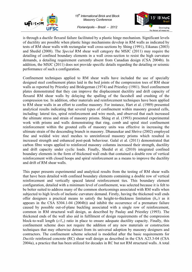
of eight walls were tested by the authors, with two additional walls adopted from literature, to derive the seismic performance for a Special RM shear wall category detailed with confined boundary elements. WALL DETAILS A total of ten walls were constructed and tested at McMaster University (two by Shedid et al. (2010)) each detailed with the confined boundary element shown in Figure 1. The walls were constructed with a half-scale true replica block modelled after the 190 mm (8”) stretcher unit common in North American construction. The use of a half-scale unit at McMaster University has previously been correlated to full-scale shear wall behaviour by Long (2006). The fully-grouted boundary elements were comprised of two masonry units (with overall dimensions of 185 mm ×185 mm) to facilitate the placement of four bars in two rows placed in the centre of each cell. These four bars had lateral reinforcement ties placed at each course height (95 mm). The confined region measured from the centreline of the lateral ties was approximately square with dimensions 105 mm × 105 mm (32% of the gross boundary element area as shown in Figure 1) with each of the four bars located at the centre of the corresponding block’s cell to ensure adequate grout bond. The vertical reinforcement was detailed with No. 10 bars with area (As) of 100 mm2 and placed in the centre of each cell with the spacing shown in Figure 1. Horizontal reinforcement was comprised of D4 deformed bars (As = 25.4 mm2) and was anchored in the boundary elements around the vertical reinforcing bars as shown in Figure 1. The D4 bars were laid in the knock-out webs of the blocks at the spacing (sh) indicated in Table 1. Lateral ties were bent into the square stirrups shown in Figure 1 and were placed by the mason during wall construction at each course at mid-height of the boundary element units. The resulting tie spacing of 95 mm is consistent with the tie spacing requirements for concrete compression members according to the CSA A23.3-04 (2004a). All wall details, including the height (hw), length (ℓw), aspect ratio (Ar), vertical reinforcement ratio (ρv), vertical reinforcement spacing (sv), horizontal reinforcement ratio (ρh), horizontal reinforcement spacing (sh) and the applied level of axial load (Pa) are presented in Table 1. In addition, the number of RC cast-in-place simulated inter-storey floor slabs of each specimen is also given in Table 1 as a test parameter. These slabs were constructed at a storey height of 1.3 m (2.6 m in full-scale) and introduced as a test parameter since it was observed by Shedid et al. (2010) that the presence of these slabs had an observable effect on cracking damage.
Figure 1: Wall 5 Cross-Section and Boundary Element Detailing
185 mm
1,800 mm
380 mm 333 mm
105 mm
105 mm
46 mm 46 mm
185 mm
15th International Brick and Block Masonry Conference
Florianópolis – Brazil – 2012
Table 1: Wall Test Parameters Wall 1 2 3 4 5 6 7 8 9 10
hw (mm) 1900 2660 3990 2660 3990 lw (mm) 1235 1803 2655
Ar 1.53 2.15 3.23 1.48 2.21 1.5 ρ v (%) 0.69 0.69 1.17 0.69 0.56 0.51 sv (mm) 380 95 380 380 380 ρh (%) 0.59 0.6 0.3 sh (mm) 2@95 1@95 P (MPa) 0.89 0.45 1.34 0.89
#Inter-storey Floor Slabs 0 1 1 2 1 2 2 0 2 0
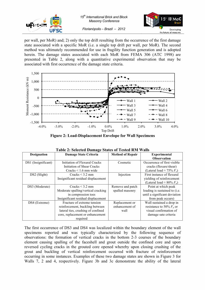
WALL PERFORMANCE QUANTIFICATION All the walls were subjected to reversed cycles of top displacement applied in a quasi-static fashion at increasing multiples of the experimentally measured yield displacement (Δy,test) with two cycles completed at each amplitude until failure occurred. Failure was defined as the point where the lateral resistance of the wall failed to reach 50% the peak resistance. Internally mounted strain gauges and externally mounted displacement transducers were positioned on the walls to measure internal strain on the vertical reinforcement, flexural curvature, base sliding and lateral displacements along the height. The test program is designed in accordance with the objectives set out by the Federal Emergency Management Agency (FEMA) document P695 (ATC 2009) for the quantification of performance-based seismic behaviour of structural components. The load displacement envelopes resulting from the static hysteretic loops generated of all the walls tested are presented in Figure 2, wherein all walls were defined by a flexural failure mechanism with a fully developed plastic hinge. Quantification of the anticipated damage patterns and behaviour of traditional rectangular RM structural walls is divided into four categories according to a predefined method of repair (MoR) by FEMA 306 (ATC 1998): Insignificant, Slight, Moderate and Extreme. These damage states have been identified to coincide with a certain level of remediation (i.e. epoxy injection of cracks) and may be integrated into the formulation of fragility functions as described by the ATC-58-1 (ATC 2011) document. There is a need to identify the occurrence of such damage states for RM walls with boundary elements, as it represents a new categorization of masonry structural wall in the Canadian design. In addition, the presence of boundary elements is likely to alter the development of damage states over conventional shear wall construction (e.g. occurrence of bar buckling). Murcia-Delco and Shing (2011) identified three damage states in RM shear walls derived from test data of rectangular RM shear walls failing in flexure. The authors related the occurrence of a damage state to a particular load condition to facilitate a survey of existing literature where data may be incomplete or missing. Gulec and Whittaker (2009) identified the occurrence of four levels of MoR, each with a set of predefined damage states in a review of experimental tests on RC squat shear walls with a variety of cross-section shapes, including walls with thickened boundary elements. The latter authors employed two methods for identification of the level of top drift associated with a specified MoR namely: 1) the drift at which each damage state associated with a certain MoR are taken (i.e. multiple points (drifts)
15th International Brick and Block Masonry Conference
Florianópolis – Brazil – 2012
per wall, per MoR) and; 2) only the top drift resulting from the occurrence of the first damage state associated with a specific MoR (i.e. a single top drift per wall, per MoR). The second method was ultimately recommended for use in fragility function generation and is adopted herein. The damage states associated with each MoR from FEMA 306 (ATC 1998) are presented in Table 2, along with a quantitative experimental observation that may be associated with first occurrence of the damage state criteria.
Figure 2: Load-Displacement Envelope for Wall Specimens
Table 2: Selected Damage States of Tested RM Walls Designation Damage State Criteria Method of Repair Experimental
Observation DS1 (Insignificant) Initiation of Flexural Cracks
Initiation of Shear Cracks Cracks < 1.6 mm wide
Cosmetic Occurrence of first visible cracks (flexure/shear)
(Lateral load ≈ 75% Fy) DS2 (Slight) Cracks < 3.2 mm
Insignificant residual displacement Injection First instance of flexural
yielding of reinforcement (Lateral load ≈ 80% Fu)
DS3 (Moderate) Cracks < 3.2 mm Moderate spalling/vertical cracking
in compression toes Insignificant residual displacement
Remove and patch spalled masonry
Point at which peak loading is sustained to (i.e. until a significant deviation
from peak occurs) DS4 (Extreme) Fracture of extreme tension
reinforcement, buckling between lateral ties, crushing of confined
core, replacement or enhancement required
Replacement or enhancement of
wall
Wall sustained a drop in resistance to 50% Fu or visual confirmation of damage sate criteria
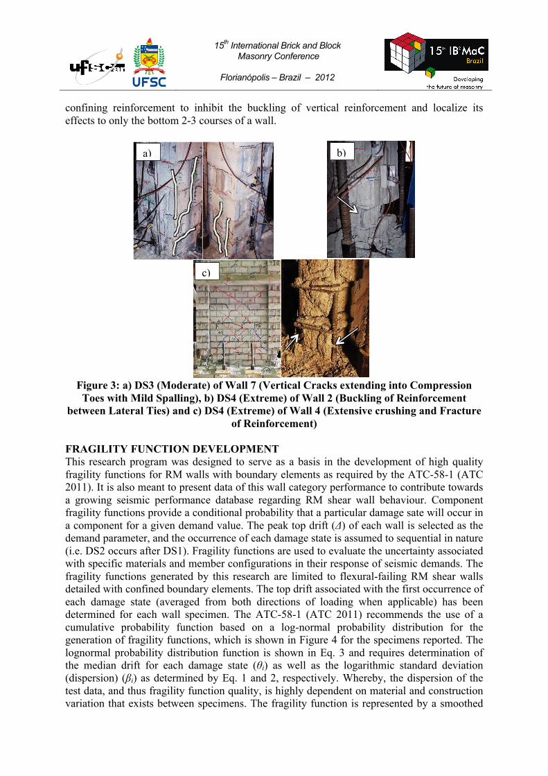
The first occurrence of DS3 and DS4 was localized within the boundary element of the wall specimens reported and was typically characterized by the following sequence of observations: the formation of vertical cracks in the bottom 2-3 courses of the boundary element causing spalling of the faceshell and grout outside the confined core and upon reversed cycling cracks in the grouted core opened whereby upon closing crushing of the grout and buckling of vertical reinforcement occurred with fracture of reinforcement occurring in some instances. Examples of these two damage states are shown in Figure 3 for Walls 7, 2 and 4, respectively. Figure 3b and 3c demonstrate the ability of the lateral
-1,500
-1,000
-500
0
500
1,000
1,500
-4.0% -3.0% -2.0% -1.0% 0.0% 1.0% 2.0% 3.0% 4.0%
Mom
ent R
esis
tanc
e (k
N·m
)
Top Drift
Wall 1 Wall 2 Wall 3 Wall 4 Wall 5 Wall 6 Wall 7 Wall 8 Wall 9 Wall 10
15th International Brick and Block Masonry Conference
Florianópolis – Brazil – 2012
confining reinforcement to inhibit the buckling of vertical reinforcement and localize its effects to only the bottom 2-3 courses of a wall.
Figure 3: a) DS3 (Moderate) of Wall 7 (Vertical Cracks extending into Compression
Toes with Mild Spalling), b) DS4 (Extreme) of Wall 2 (Buckling of Reinforcement between Lateral Ties) and c) DS4 (Extreme) of Wall 4 (Extensive crushing and Fracture
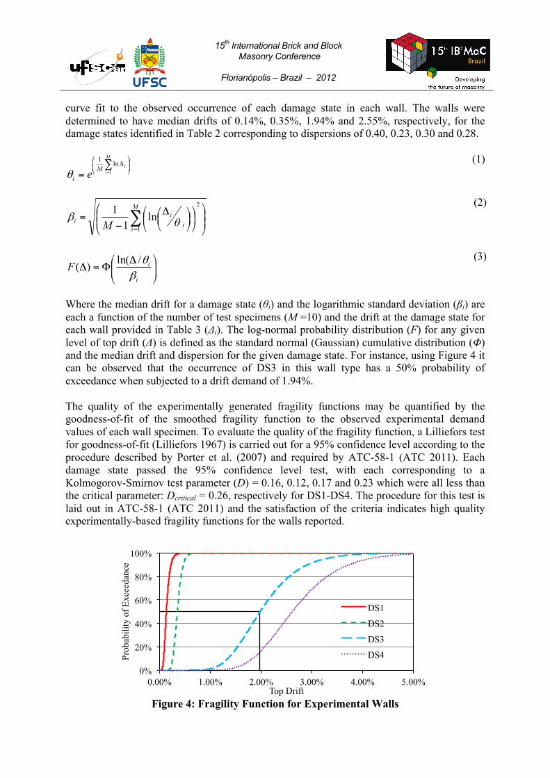
of Reinforcement) FRAGILITY FUNCTION DEVELOPMENT This research program was designed to serve as a basis in the development of high quality fragility functions for RM walls with boundary elements as required by the ATC-58-1 (ATC 2011). It is also meant to present data of this wall category performance to contribute towards a growing seismic performance database regarding RM shear wall behaviour. Component fragility functions provide a conditional probability that a particular damage sate will occur in a component for a given demand value. The peak top drift (Δ) of each wall is selected as the demand parameter, and the occurrence of each damage state is assumed to sequential in nature (i.e. DS2 occurs after DS1). Fragility functions are used to evaluate the uncertainty associated with specific materials and member configurations in their response of seismic demands. The fragility functions generated by this research are limited to flexural-failing RM shear walls detailed with confined boundary elements. The top drift associated with the first occurrence of each damage state (averaged from both directions of loading when applicable) has been determined for each wall specimen. The ATC-58-1 (ATC 2011) recommends the use of a cumulative probability function based on a log-normal probability distribution for the generation of fragility functions, which is shown in Figure 4 for the specimens reported. The lognormal probability distribution function is shown in Eq. 3 and requires determination of the median drift for each damage state (θi) as well as the logarithmic standard deviation (dispersion) (βi) as determined by Eq. 1 and 2, respectively. Whereby, the dispersion of the test data, and thus fragility function quality, is highly dependent on material and construction variation that exists between specimens. The fragility function is represented by a smoothed
a) b)
c)
15th International Brick and Block Masonry Conference
Florianópolis – Brazil – 2012
curve fit to the observed occurrence of each damage state in each wall. The walls were determined to have median drifts of 0.14%, 0.35%, 1.94% and 2.55%, respectively, for the damage states identified in Table 2 corresponding to dispersions of 0.40, 0.23, 0.30 and 0.28.
⎟⎟⎠
⎞⎜⎜⎝
⎛Δ∑
= =
M
iiM
i e 1
ln1
θ (1)
⎟⎟⎠
⎞⎜⎜⎝
⎛⎟⎠⎞
⎜⎝⎛
⎟⎠⎞
⎜⎝⎛Δ
−= ∑
=
M
i ii
i M 1
2
ln1
1θβ
(2)
⎟⎟⎠
⎞⎜⎜⎝
⎛ ΔΦ=Δ
i
iFβθ/ln()(
(3)
Where the median drift for a damage state (θi) and the logarithmic standard deviation (βi) are each a function of the number of test specimens (M =10) and the drift at the damage state for each wall provided in Table 3 (Δi). The log-normal probability distribution (F) for any given level of top drift (Δ) is defined as the standard normal (Gaussian) cumulative distribution (Φ) and the median drift and dispersion for the given damage state. For instance, using Figure 4 it can be observed that the occurrence of DS3 in this wall type has a 50% probability of exceedance when subjected to a drift demand of 1.94%. The quality of the experimentally generated fragility functions may be quantified by the goodness-of-fit of the smoothed fragility function to the observed experimental demand values of each wall specimen. To evaluate the quality of the fragility function, a Lilliefors test for goodness-of-fit (Lilliefors 1967) is carried out for a 95% confidence level according to the procedure described by Porter et al. (2007) and required by ATC-58-1 (ATC 2011). Each damage state passed the 95% confidence level test, with each corresponding to a Kolmogorov-Smirnov test parameter (D) = 0.16, 0.12, 0.17 and 0.23 which were all less than the critical parameter: Dcritical = 0.26, respectively for DS1-DS4. The procedure for this test is laid out in ATC-58-1 (ATC 2011) and the satisfaction of the criteria indicates high quality experimentally-based fragility functions for the walls reported.
Figure 4: Fragility Function for Experimental Walls
0%
20%
40%
60%
80%
100%
0.00% 1.00% 2.00% 3.00% 4.00% 5.00%
Prob
abili
ty o
f Exc
eeda
nce
Top Drift
DS1
DS2
DS3
DS4

15th International Brick and Block Masonry Conference
Florianópolis – Brazil – 2012
Murcia-Delso and Shing (2011) determined values of θi = 0.31%, 0.87% and 1.51% for DS2, DS3 and DS4 for rectangular RM shear walls failing in flexure corresponding to values of β = 0.45, 0.35 and 0.30, respectively. The walls presented in this paper indicate a nominal improvement of θi of the slight damage state (DS2), however, the walls with boundary elements increased the median drift of DS3 and DS4 by a significantly large margin of 1.07% and 1.04% drift, respectively. CONCLUSIONS The ten walls reported were all detailed with confined boundary elements detailed as a minimum level of wall confinement to impede the buckling of vertical reinforcement and instability of flexural RM walls commonly associated with high levels of ductility demand. A set of predefined damage states have been developed for this wall type based on accepted performance parameters of RM flexural structural walls with special consideration of the performance of the boundary element. The test data presented resulted in a high quality fragility function with median drifts of 0.14%, 0.35%, 1.94% and 2.55% corresponding to a dispersion of 0.40, 0.23, 0.30 and 0.28 for DS1 – DS4, respectively. The results presented here indicate that the addition of a confined boundary element has the potential to improve the level drift associated with Moderate and Extreme Damage States. It is hoped by the authors that the data presented here may be used in the future to develop more robust fragility functions as more test data of this wall category becomes available. Furthermore, these results support the inclusion of Special RM structural walls with confined boundary elements within future masonry design codes as well within the development of future performance-based seismic design codes. ACKNOWLEDGEMENTS Financial support has been provided by the McMaster University Centre for Effective Design of Structures (CEDS) funded through the Ontario Research and Development Challenge Fund (ORDCF) as well as the Natural Sciences and Engineering Research Council (NSERC) of Canada. Provision of mason time by Ontario Masonry Contractors Association (OMCA) and Canada Masonry Design Centre is appreciated. The supply of half-scale blocks by the Canadian Concrete Masonry Producers Association (CCMPA) is gratefully acknowledged. REFERENCES Applied Technology Council (ATC). Evaluation of Earthquake Damaged Concrete and Masonry Wall Buildings, FEMA 306, Washington D.C., USA, 1998. Applied Technology Council (ATC). Quantification of Building Seismic Performance Factors, FEMA P695, Washington D.C., USA, 2009. Applied Technology Council (ATC). Guidelines for Seismic Performance Assessment of Buildings (75% Draft): Volume 1 – Methodology, ATC 58-1, Redwood City, CA, 2011. Canadian Standards Association (CSA). Design of masonry structures: CSA S304.1-04, Mississauga, Canada, 2004a (R2010).

15th International Brick and Block Masonry Conference
Florianópolis – Brazil – 2012
Canadian Standards Association (CSA). Design of concrete structures: CSA A23.3-04, Mississauga, Canada, 2004b (R2010). Dhanasekar, M., Shrive, N. G. “Strength and deformation of confined and unconfined grouted masonry,” ACI Journal, 99 (6), (2002), pp 819-826. Eikanas, I.K., Behavior of Concrete Masonry Shear Walls with Varying Aspect Ratio and Flexural Reinforcement, M.S. Thesis, Washington State University, Pullman, WA, U.S.A., 2003. Galal, K., Farnia, N. and Pekau, O.A. “Upgrading the seismic performance of reinforced masonry columns using CFRP wraps,” Journal of Composites for Construction posted ahead of print, 2011 doi:10.1061/(ASCE)CC.1943-5614.0000252. Gules, C.K. and Whittaker, A.S. Performance-Based Assessment and Design of Squat Reinforced Concrete Shear Walls, Technical Report MCEER-09-0010, University of Buffalo, State university of New York, U.S.A 2009. Hart, G.C., Sajjad, N., Kingsley, G.R., Noland, J.L. “Analytical stress-strain curves for grouted concrete masonry,” The Masonry Society Journal, 8 (1), 1989, pp T21-T34. Lilliefors, H.W. “On the Kolmogorov-Smirnov test for normality with mean and variance unknown,” Journal of the American Statistical Association, 62(318), 1967, pp 399-402. Long, L.M. (2006). Behaviour of Half-Scale Reinforced Concrete Masonry Shear Walls, M.A.Sc. Thesis, McMaster University, Hamilton, Canada, 2006. Masonry Standards Joint Committee (MSJC). Building Code Requirements for Masonry Structures, TMS 402/ASCE 5/ACI 530, The Masonry Society (TMS), American Society of Civil Engineers (ASCE), American Concrete Institute (ACI), Boulder, New York and Detroit, USA, 2011. Murcia-Delso, J., and Shing, B. “Fragility curves for in-plane seismic performance of reinforced masonry walls,” Proc., 11th North American Masonry Conference, Minneapolis, Minnesota, USA, 2011, Paper #2.04-3. Paulay, T., and Priestley, M.J.N. “Stability of ductile shear walls,” ACI Structural Journal, 90 (4), 1993, pp 385-392. Porter K., Kennedy, R. and Bachman, R. “Creating fragility functions for performance-based earthquake engineering,” Earthquake Spectra, 23 (2), 2007, pp 471-489. Priestley, M.J.N., Bridgeman, D.O. “Seismic resistance of brick masonry walls,” Bulletin of the New Zealand National Society for Earthquake Engineering, 7 (4), 1974, pp 167-187. Priestley, M.J.N. “Ductility of unconfined and confined masonry shear walls,” The Masonry Society Journal, 1 (2), 1981, pp T28-T39.

15th International Brick and Block Masonry Conference
Florianópolis – Brazil – 2012
Shedid, M.T., El-Dakhakhni, W.W., and Drysdale, R.G. “Behavior of fully grouted reinforced concrete masonry shear walls failing in flexure: experimental results,” J. Struct. Eng., 134 (11), 2008, pp 1754-1767. Shedid, M.T., El-Dakhakhni, W.W., and Drysdale, R.G. “Alternative strategies to enhance the seismic performance of reinforced concrete block shear wall systems.” J. Struct. Eng., 136 (6), 2010, 676-689. Shing, P.B., Noland, J.L., Spaeh, H.P., Klamerus, E.W., and Schuller, M.P. Response of Single-Story Reinforced Masonry Shear Walls to In-Plane Lateral Loads, Report No. 3.1(a)-2, US-Japan Coordinated Program for Masonry Building Research, University of Colorado at Boulder, Boulder, CO, U.S.A., 1991. Shing, P.B., Carter, E.W., Noland, J.L. “Influence of confining steel on flexural response of reinforced masonry shear walls,” The Masonry Society Journal, 11 (2), 1993, pp T21-T34.