Embed Size (px)
Citation preview
ICFComplete Valve Stations
Technical leafletREFRIGERATION AND AIR CONDITIONING
Technical leaflet The ICF control solution
� DKRCI.PD.FT0.A3.�� / 5�0H1�7� © Danfoss A/S (USCO/MR), 11 - �006
Contents Page
Introduction. . . . . . . . . . . . . . . . . . . . . . . . . . . . . . . . . . . . . . . . . . . . . . . . . . . . . . . . . . . . . . . . . . . . . . . . . . . . . . . . . . . . . . . 3
Features . . . . . . . . . . . . . . . . . . . . . . . . . . . . . . . . . . . . . . . . . . . . . . . . . . . . . . . . . . . . . . . . . . . . . . . . . . . . . . . . . . . . . . . . . . . 3
Technical data . . . . . . . . . . . . . . . . . . . . . . . . . . . . . . . . . . . . . . . . . . . . . . . . . . . . . . . . . . . . . . . . . . . . . . . . . . . . . . . . . . . . . 3
Design . . . . . . . . . . . . . . . . . . . . . . . . . . . . . . . . . . . . . . . . . . . . . . . . . . . . . . . . . . . . . . . . . . . . . . . . . . . . . . . . . . . . . . . . . . . . 4
Function modules . . . . . . . . . . . . . . . . . . . . . . . . . . . . . . . . . . . . . . . . . . . . . . . . . . . . . . . . . . . . . . . . . . . . . . . . . . . . . 4
Housing . . . . . . . . . . . . . . . . . . . . . . . . . . . . . . . . . . . . . . . . . . . . . . . . . . . . . . . . . . . . . . . . . . . . . . . . . . . . . . . . . . . . . . . 4
Approvals . . . . . . . . . . . . . . . . . . . . . . . . . . . . . . . . . . . . . . . . . . . . . . . . . . . . . . . . . . . . . . . . . . . . . . . . . . . . . . . . . . . . . . . . . 4
Description of the function modules . . . . . . . . . . . . . . . . . . . . . . . . . . . . . . . . . . . . . . . . . . . . . . . . . . . . . . . . . . . . 5 - 6
Function module configurations . . . . . . . . . . . . . . . . . . . . . . . . . . . . . . . . . . . . . . . . . . . . . . . . . . . . . . . . . . . . . . . . . . . 7
Material specification . . . . . . . . . . . . . . . . . . . . . . . . . . . . . . . . . . . . . . . . . . . . . . . . . . . . . . . . . . . . . . . . . . . . . . . . . . 8 - 1�
Configuration examples - ICF with six function modules . . . . . . . . . . . . . . . . . . . . . . . . . . . . . . . . . . . . . . . . 13, 15
Configuration examples - ICF with four function modules . . . . . . . . . . . . . . . . . . . . . . . . . . . . . . . . . . . . . . . 14, 16
Application examples. . . . . . . . . . . . . . . . . . . . . . . . . . . . . . . . . . . . . . . . . . . . . . . . . . . . . . . . . . . . . . . . . . . . . . . . . 17 - 19
Ordering ICF �0-6 with six function modules (STANDARD configurations only) . . . . . . . . . . . . . . . . . . . . . . �0
Ordering ICF �0-4 with four function modules (STANDARD configurations only) . . . . . . . . . . . . . . . . . . . . �1
Ordering ICF (�5-40)-6 with six function modules (STANDARD configurations only) . . . . . . . . . . . . . . . . . ��
Ordering ICF (�5-40)-4 with four function modules (STANDARD configurations only) . . . . . . . . . . . . . . . . �3
Ordering ICF �0-6 with six function modules (including special order configurations). . . . . . . . . . . . . . . �4
Ordering ICF �0-4 with four function modules (including special order configurations). . . . . . . . . . . . . . �5
Ordering ICF (�5-40)-6 with six function modules (including special order configurations). . . . . . . . . . . �6
Ordering ICF (�5-40)-4 with four function modules (including special order configurations) . . . . . . . . . �7
Ordering accessories. . . . . . . . . . . . . . . . . . . . . . . . . . . . . . . . . . . . . . . . . . . . . . . . . . . . . . . . . . . . . . . . . . . . . . . . . . . . . . �8
Dimensions and weights . . . . . . . . . . . . . . . . . . . . . . . . . . . . . . . . . . . . . . . . . . . . . . . . . . . . . . . . . . . . . . . . . . . . . . �9 - 3�
ICAD Motor-actuator for ICM module. . . . . . . . . . . . . . . . . . . . . . . . . . . . . . . . . . . . . . . . . . . . . . . . . . . . . . . . . . 33 - 39
Features . . . . . . . . . . . . . . . . . . . . . . . . . . . . . . . . . . . . . . . . . . . . . . . . . . . . . . . . . . . . . . . . . . . . . . . . . . . . . . . . . . . . . . 33
Technical data (actuator) . . . . . . . . . . . . . . . . . . . . . . . . . . . . . . . . . . . . . . . . . . . . . . . . . . . . . . . . . . . . . . . . . . 33- 34
Approvals . . . . . . . . . . . . . . . . . . . . . . . . . . . . . . . . . . . . . . . . . . . . . . . . . . . . . . . . . . . . . . . . . . . . . . . . . . . . . . . . . . . . 34
Function. . . . . . . . . . . . . . . . . . . . . . . . . . . . . . . . . . . . . . . . . . . . . . . . . . . . . . . . . . . . . . . . . . . . . . . . . . . . . . . . . . . . . . 34
ICAD-UPS Uninterruptible power supply for ICAD . . . . . . . . . . . . . . . . . . . . . . . . . . . . . . . . . . . . . . . . . . 35 - 36
General operation . . . . . . . . . . . . . . . . . . . . . . . . . . . . . . . . . . . . . . . . . . . . . . . . . . . . . . . . . . . . . . . . . . . . . . . . . . . . 37
Alarms. . . . . . . . . . . . . . . . . . . . . . . . . . . . . . . . . . . . . . . . . . . . . . . . . . . . . . . . . . . . . . . . . . . . . . . . . . . . . . . . . . . . . . . . 38
Parameter list . . . . . . . . . . . . . . . . . . . . . . . . . . . . . . . . . . . . . . . . . . . . . . . . . . . . . . . . . . . . . . . . . . . . . . . . . . . . . 38 -39
Technical leaflet The ICF control solution
© Danfoss A/S (USCO/MR), 11 - �006 DKRCI.PD.FT0.A3.�� / 5�0H1�7� 3
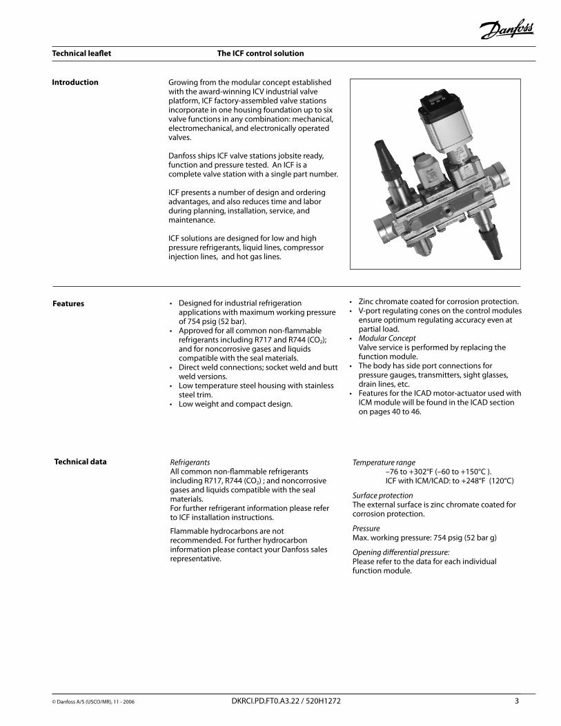
Introduction Growing from the modular concept established with the award-winning ICV industrial valve platform, ICF factory-assembled valve stations incorporate in one housing foundation up to six valve functions in any combination: mechanical, electromechanical, and electronically operated valves.
Danfoss ships ICF valve stations jobsite ready, function and pressure tested. An ICF is a complete valve station with a single part number.
ICF presents a number of design and ordering advantages, and also reduces time and labor during planning, installation, service, and maintenance.
ICF solutions are designed for low and high pressure refrigerants, liquid lines, compressor injection lines, and hot gas lines.
Features Designed for industrial refrigeration applications with maximum working pressure of 754 psig (5� bar).
Approved for all common non-flammable refrigerants including R717 and R744 (CO�); and for noncorrosive gases and liquids compatible with the seal materials.
Direct weld connections; socket weld and butt weld versions.
Low temperature steel housing with stainless steel trim.
Low weight and compact design.
•
•
•
•
•
Zinc chromate coated for corrosion protection. V-port regulating cones on the control modules
ensure optimum regulating accuracy even at partial load.
ModularConcept Valve service is performed by replacing the function module.
The body has side port connections for pressure gauges, transmitters, sight glasses, drain lines, etc.
Features for the ICAD motor-actuator used with ICM module will be found in the ICAD section on pages 40 to 46.
••
•
•
•
RefrigerantsAll common non-flammable refrigerants including R717, R744 (CO�) ; and noncorrosive gases and liquids compatible with the seal materials.For further refrigerant information please refer to ICF installation instructions. Flammable hydrocarbons are not recommended. For further hydrocarbon information please contact your Danfoss sales representative.
Temperaturerange –76 to +30�°F (–60 to +150°C ). ICF with ICM/ICAD: to +�48°F (1�0°C)
SurfaceprotectionThe external surface is zinc chromate coated for corrosion protection.
PressureMax. working pressure: 754 psig (5� bar g)
Openingdifferentialpressure:Please refer to the data for each individual function module.
Technical data
Technical leaflet The ICF control solution
4 DKRCI.PD.FT0.A3.�� / 5�0H1�7� © Danfoss A/S (USCO/MR), 11 - �006
Design
For specific approval information, please contactDanfoss. The ICF concept is designed to fulfill global refrigeration requirements.
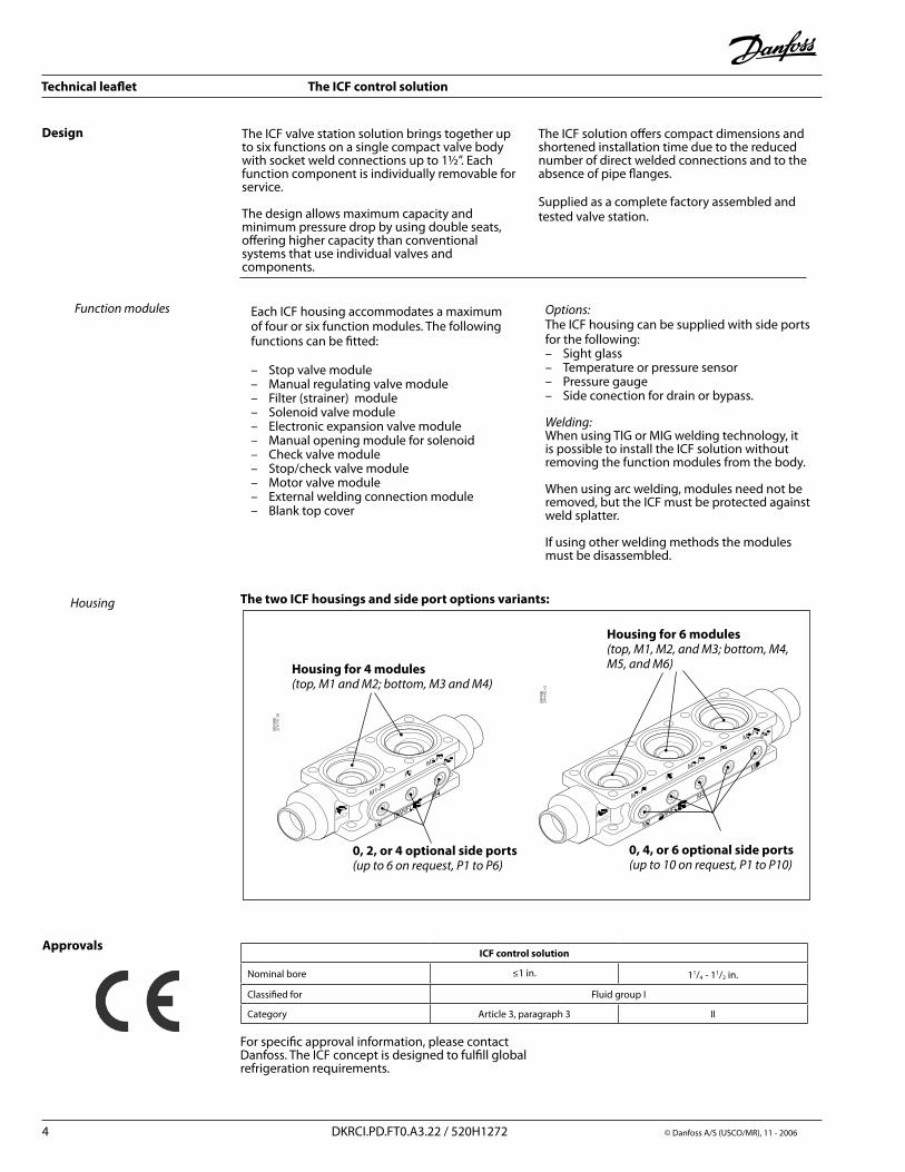
The two ICF housings and side port options variants:
The ICF valve station solution brings together up to six functions on a single compact valve body with socket weld connections up to 1½”. Each function component is individually removable for service.
The design allows maximum capacity and minimum pressure drop by using double seats, offering higher capacity than conventional systems that use individual valves and components.
Housing for 4 modules (top,M1andM2;bottom,M3andM4)
Housing for 6 modules(top,M1,M2,andM3;bottom,M4,M5,andM6)
0, 2, or 4 optional side ports(upto6onrequest,P1toP6)
0, 4, or 6 optional side ports(upto10onrequest,P1toP10)
Housing
Approvals
Each ICF housing accommodates a maximum of four or six function modules. The following functions can be fitted:
– Stop valve module– Manual regulating valve module– Filter (strainer) module– Solenoid valve module– Electronic expansion valve module– Manual opening module for solenoid– Check valve module– Stop/check valve module– Motor valve module– External welding connection module– Blank top cover
Functionmodules Options:The ICF housing can be supplied with side ports for the following:– Sight glass – Temperature or pressure sensor – Pressure gauge – Side conection for drain or bypass.
Welding:When using TIG or MIG welding technology, it is possible to install the ICF solution without removing the function modules from the body.
When using arc welding, modules need not be removed, but the ICF must be protected against weld splatter.
If using other welding methods the modules must be disassembled.
ICF control solution
Nominal bore ≤1 in. 11/4 - 11/� in.
Classified for Fluid group I
Category Article 3, paragraph 3 II
The ICF solution offers compact dimensions and shortened installation time due to the reduced number of direct welded connections and to the absence of pipe flanges.
Supplied as a complete factory assembled and tested valve station.
Technical leaflet The ICF control solution
5 DKRCI.PD.FT0.A3.�� / 5�0H1�7� © Danfoss A/S (USCO/MR), 11 - �006
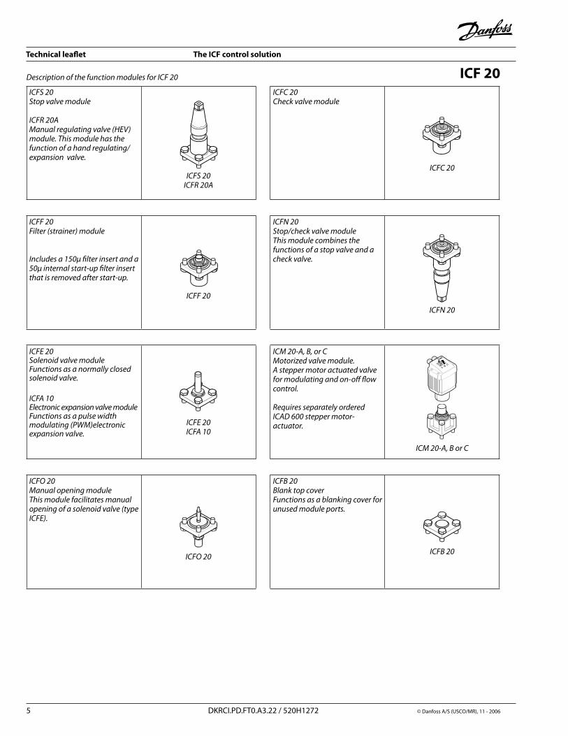
ICFS20Stopvalvemodule
ICFR20AManualregulatingvalve(HEV)module.Thismodulehasthefunctionofahandregulating/expansionvalve.
ICFS20ICFR20A
ICFC20Checkvalvemodule
ICFC20
ICFF20Filter(strainer)module
Includesa150µfilterinsertanda50µinternalstart-upfilterinsertthatisremovedafterstart-up.
ICFF20
ICFN20Stop/checkvalvemoduleThismodulecombinesthefunctionsofastopvalveandacheckvalve.
ICFN20
ICFE20SolenoidvalvemoduleFunctionsasanormallyclosedsolenoidvalve.
ICFA10ElectronicexpansionvalvemoduleFunctionsasapulsewidthmodulating(PWM)electronicexpansionvalve.
ICFE20ICFA10
ICM20-A,B,orCMotorizedvalvemodule.Asteppermotoractuatedvalveformodulatingandon-offflowcontrol.RequiresseparatelyorderedICAD600steppermotor-actuator.
ICM20-A,BorC
ICFO20ManualopeningmoduleThismodulefacilitatesmanualopeningofasolenoidvalve(typeICFE).
ICFO20
ICFB20BlanktopcoverFunctionsasablankingcoverforunusedmoduleports.
ICFB20
DescriptionofthefunctionmodulesforICF20 ICF 20
Technical leaflet The ICF control solution
6 DKRCI.PD.FT0.A3.�� / 5�0H1�7� © Danfoss A/S (USCO/MR), 11 - �006
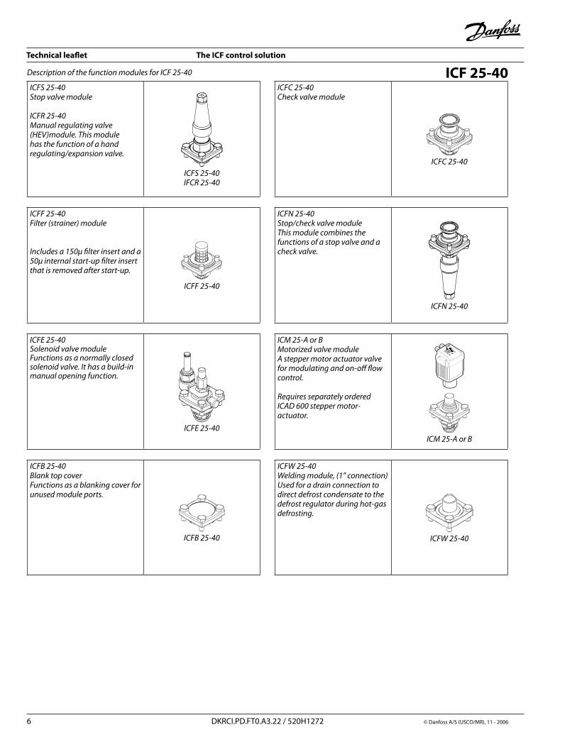
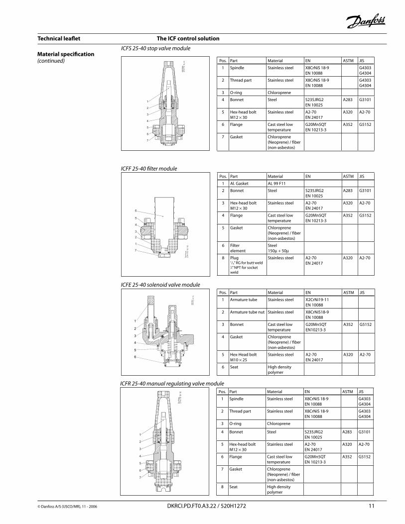
ICFS25-40Stopvalvemodule
ICFR25-40Manualregulatingvalve(HEV)module.Thismodulehasthefunctionofahandregulating/expansionvalve.
ICFS25-40IFCR25-40
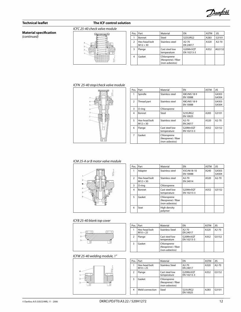
ICFC25-40Checkvalvemodule
ICFC25-40
ICFF25-40Filter(strainer)module
Includesa150µfilterinsertanda50µinternalstart-upfilterinsertthatisremovedafterstart-up.
ICFF25-40
ICFN25-40Stop/checkvalvemoduleThismodulecombinesthefunctionsofastopvalveandacheckvalve.
ICFN25-40
ICFE25-40SolenoidvalvemoduleFunctionsasanormallyclosedsolenoidvalve.Ithasabuild-inmanualopeningfunction.
ICFE25-40
ICM25-AorBMotorizedvalvemoduleAsteppermotoractuatorvalveformodulatingandon-offflowcontrol.
RequiresseparatelyorderedICAD600steppermotor-actuator.
ICM25-AorB
ICFB25-40BlanktopcoverFunctionsasablankingcoverforunusedmoduleports.
ICFB25-40
ICFW25-40Weldingmodule,(1”connection)Usedforadrainconnectiontodirectdefrostcondensatetothedefrostregulatorduringhot-gasdefrosting.
ICFW25-40
DescriptionofthefunctionmodulesforICF25-40 ICF 25-40
Technical leaflet The ICF control solution
7 DKRCI.PD.FT0.A3.�� / 5�0H1�7� © Danfoss A/S (USCO/MR), 11 - �006
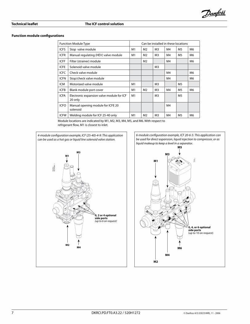
Function Module Type Can be installed in these locations
ICFS Stop valve module M1 M� M3 M4 M5 M6
ICFR Manual regulating (HEV) valve module M1 M� M3 M4 M5 M6
ICFF Filter (strainer) module M� M4 M6
ICFE Solenoid valve module M3
ICFC Check valve module M4 M6
ICFN Stop/check valve module M4 M6
ICM Motorized valve module M1 M3 M5
ICFB Blank module port cover M1 M� M3 M4 M5 M6
ICFA Electronic expansion valve module for ICF �0 only
M1 M3 M5
ICFO Manual opening module for ICFE �0 solenoid
M4
ICFW Welding module for ICF �5-40 only M1 M� M3 M4 M5 M6
Module locations are indicated by M1, M�, M3, M4, M5, and M6. With respect to refrigerant flow, M1 is closest to inlet.
Function module configurations
Dan
foss
M27
H00
04_1
0, 2 or 4 optional side ports(upto6onrequest)
4-moduleconfigurationexample,ICF(25-40)-4-9:Thisapplicationcanbeusedasahotgasorliquidlinesolenoidvalvestation.
0, 4, or 6 optional side ports (up to 10 on request)
6-moduleconfigurationexample,ICF20-6-5:Thisapplicationcanbeusedfordirectexpansion,liquidinjectiontocompressor,orasliquidmakeuptokeepalevelinaseparator.
Technical leaflet The ICF control solution
© Danfoss A/S (USCO/MR), 11 - �006 DKRCI.PD.FT0.A3.�� / 5�0H1�7� 8
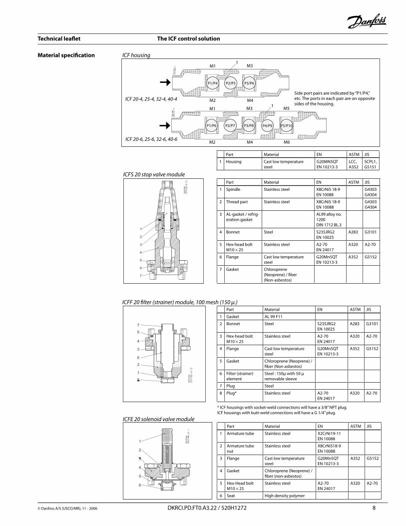
Material specification ICFhousing
Part Material EN ASTM JIS
1 Housing Cast low temperature steel
G�0MN5QTEN 10�13-3
LCC, A35�
SCPL1, G5151
ICFF20filter(strainer)module,100mesh(150μ.)Part Material EN ASTM JIS
1 Gasket AL 99 F11
� Bonnet Steel S�35JRG�EN 100�5
A�83 G3101
3 Hex-head boltM10 × �5
Stainless steel A�-70EN �4017
A3�0 A�-70
4 Flange Cast low temperature steel
G�0Mn5QTEN 10�13-3
A35� G515�
5 Gasket Chloroprene (Neoprene) / fiber (Non-asbestos)
6 Filter (strainer)element
Steel : 150μ with 50 μ removable sleeve
7 Plug Steel
8 Plug* Stainless steel A�-70EN �4017
A3�0 A�-70
ICFS20stopvalvemodulePart Material EN ASTM JIS
1 Spindle Stainless steel X8CrNiS 18-9EN 10088
G4303G4304
� Thread part Stainless steel X8CrNiS 18-9EN 10088
G4303G4304
3 AL-gasket / refrig-eration gasket
AL99 alloy no. 1�00DIN 171� BL.3
4 Bonnet Steel S�35JRG�EN 100�5
A�83 G3101
5 Hex-head boltM10 × �5
Stainless steel A�-70EN �4017
A3�0 A�-70
6 Flange Cast low temperature steel
G�0Mn5QTEN 10�13-3
A35� G515�
7 Gasket Chloroprene (Neoprene) / fiber(Non-asbestos)
ICFE20solenoidvalvemodulePart Material EN ASTM JIS
1 Armature tube Stainless steel X�CrNi19-11EN 10088
� Armature tube nut
Stainless steel X8CrNiS18-9EN 10088
3 Flange Cast low temperature steel
G�0Mn5QTEN 10�13-3
A35� G515�
4 Gasket Chloroprene (Neoprene) /fiber (non-asbestos)
5 Hex-Head boltM10 × �5
Stainless steel A�-70EN �4017
A3�0 A�-70
6 Seat High density polymer
M1
M�
M3
M4
M5
M6
1
P1/P6 P5/P10P4/P9P3/P8P�/P7
1M1
M�
M3
M4
P1/P4 P3/P6P�/P5
Side port pairs are indicated by “P1/P4,” etc. The ports in each pair are on opposite sides of the housing.
* ICF housings with socket-weld connections will have a 3/8” NPT plug. ICF housings with butt-weld connections will have a G 1/4” plug.
ICF20-4,25-4,32-4,40-4
ICF20-6,25-6,32-6,40-6
Technical leaflet The ICF control solution
9 DKRCI.PD.FT0.A3.�� / 5�0H1�7� © Danfoss A/S (USCO/MR), 11 - �006
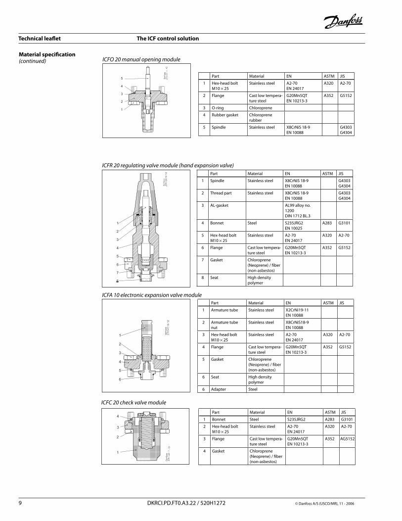
Material specification(continued) ICFO20manualopeningmodule
Part Material EN ASTM JIS
1 Hex-head boltM10 × �5
Stainless steel A�-70EN �4017
A3�0 A�-70
� Flange Cast low tempera-ture steel
G�0Mn5QTEN 10�13-3
A35� G515�
3 O-ring Chloroprene
4 Rubber gasket Chloroprene rubber
5 Spindle Stainless steel X8CrNiS 18-9EN 10088
G4303G4304
ICFR20regulatingvalvemodule(handexpansionvalve)Part Material EN ASTM JIS
1 Spindle Stainless steel X8CrNiS 18-9EN 10088
G4303G4304
� Thread part Stainless steel X8CrNiS 18-9EN 10088
G4303G4304
3 AL-gasket AL99 alloy no. 1�00DIN 171� BL.3
4 Bonnet Steel S�35JRG�EN 100�5
A�83 G3101
5 Hex-head boltM10 × �5
Stainless steel A�-70EN �4017
A3�0 A�-70
6 Flange Cast low tempera-ture steel
G�0Mn5QTEN 10�13-3
A35� G515�
7 Gasket Chloroprene (Neoprene) / fiber(non-asbestos)
8 Seat High density polymer
ICFA10electronicexpansionvalvemodulePart Material EN ASTM JIS
1 Armature tube Stainless steel X�CrNi19-11EN 10088
� Armature tube nut
Stainless steel X8CrNiS18-9EN 10088
3 Hex-head bolt M10 × �5
Stainless steel A�-70EN �4017
A3�0 A�-70
4 Flange Cast low tempera-ture steel
G�0Mn5QTEN 10�13-3
A35� G515�
5 Gasket Chloroprene (Neoprene) / fiber(non-asbestos)
6 Seat High density polymer
6 Adapter Steel
ICFC20checkvalvemodule
Part Material EN ASTM JIS
1 Bonnet Steel S�35JRG� A�83 G3101
� Hex-head boltM10 × �5
Stainless steel A�-70EN �4017
A3�0 A�-70
3 Flange Cast low tempera-ture steel
G�0Mn5QTEN 10�13-3
A35� AG515�
4 Gasket Chloroprene (Neoprene) / fiber(non-asbestos)
Technical leaflet The ICF control solution
© Danfoss A/S (USCO/MR), 11 - �006 DKRCI.PD.FT0.A3.�� / 5�0H1�7� 10
Material specification(continued)
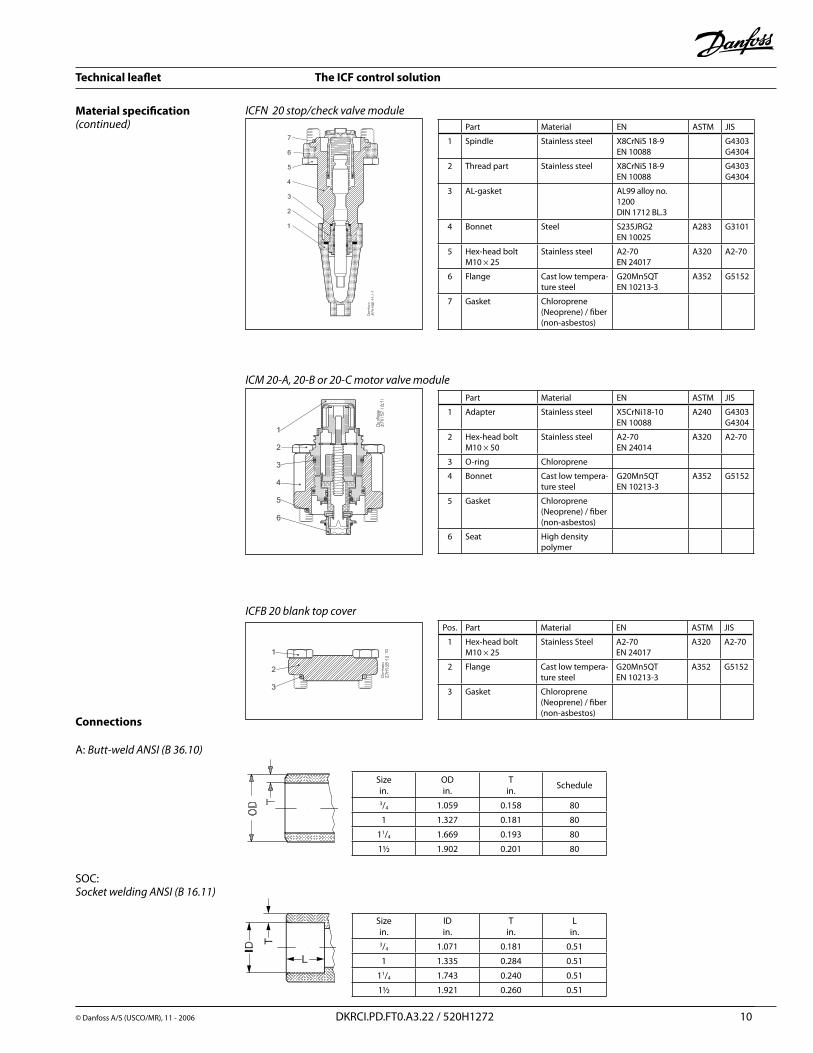
ICFN20stop/checkvalvemodule
ICM20-A,20-Bor20-Cmotorvalvemodule
Part Material EN ASTM JIS
1 Spindle Stainless steel X8CrNiS 18-9EN 10088
G4303G4304
� Thread part Stainless steel X8CrNiS 18-9EN 10088
G4303G4304
3 AL-gasket AL99 alloy no. 1�00DIN 171� BL.3
4 Bonnet Steel S�35JRG�EN 100�5
A�83 G3101
5 Hex-head boltM10 × �5
Stainless steel A�-70EN �4017
A3�0 A�-70
6 Flange Cast low tempera-ture steel
G�0Mn5QTEN 10�13-3
A35� G515�
7 Gasket Chloroprene (Neoprene) / fiber(non-asbestos)
Part Material EN ASTM JIS
1 Adapter Stainless steel X5CrNi18-10EN 10088
A�40 G4303G4304
� Hex-head boltM10 × 50
Stainless steel A�-70EN �4014
A3�0 A�-70
3 O-ring Chloroprene
4 Bonnet Cast low tempera-ture steel
G�0Mn5QTEN 10�13-3
A35� G515�
5 Gasket Chloroprene (Neoprene) / fiber(non-asbestos)
6 Seat High density polymer
Pos. Part Material EN ASTM JIS
1 Hex-head boltM10 × �5
Stainless Steel A�-70EN �4017
A3�0 A�-70
� Flange Cast low tempera-ture steel
G�0Mn5QTEN 10�13-3
A35� G515�
3 Gasket Chloroprene (Neoprene) / fiber(non-asbestos)
ICFB20blanktopcover
Connections
A: Butt-weldANSI(B36.10)
SOC: SocketweldingANSI(B16.11)
Sizein.
ODin.
Tin. Schedule
3/4 1.059 0.158 80
1 1.3�7 0.181 80
11/4 1.669 0.193 80
1½ 1.90� 0.�01 80
Sizein.
IDin.
Tin.
Lin.
3/4 1.071 0.181 0.51
1 1.335 0.�84 0.51
11/4 1.743 0.�40 0.51
1½ 1.9�1 0.�60 0.51
Technical leaflet The ICF control solution
© Danfoss A/S (USCO/MR), 11 - �006 DKRCI.PD.FT0.A3.�� / 5�0H1�7� 11
Material specification(continued)
ICFF25-40filtermodulePos. Part Material EN ASTM JIS
1 Al. Gasket AL 99 F11
� Bonnet Steel S�35JRG�EN 100�5
A�83 G3101
3 Hex-head boltM1� × 30
Stainless steel A�-70EN �4017
A3�0 A�-70
4 Flange Cast steel low temperature
G�0Mn5QTEN 10�13-3
A35� G515�
5 Gasket Chloroprene (Neoprene) / fiber(non-asbestos)
6 Filter element
Steel150m + 50m
8 Plug 1/4” RG for butt-weld3/8” NPT for socket weld
Stainless steel A�-70EN �4017
A3�0 A�-70
ICFS25-40stopvalvemodule
Pos. Part Material EN ASTM JIS
1 Spindle Stainless steel X8CrNiS 18-9EN 10088
G4303G4304
� Thread part Stainless steel X8CrNiS 18-9EN 10088
G4303G4304
3 O-ring Chloroprene
4 Bonnet Steel S�35JRG�EN 100�5
A�83 G3101
5 Hex-head boltM1� × 30
Stainless steel A�-70EN �4017
A3�0 A�-70
6 Flange Cast steel low temperature
G�0Mn5QTEN 10�13-3
A35� G515�
7 Gasket Chloroprene (Neoprene) / fiber(non-asbestos)
ICFE25-40solenoidvalvemodulePos. Part Material EN ASTM JIS
1 Armature tube Stainless steel X�CrNi19-11EN 10088
� Armature tube nut Stainless steel X8CrNiS18-9EN 10088
3 Bonnet Cast steel low temperature
G�0Mn5QT EN10�13-3
A35� G515�
4 Gasket Chloroprene (Neoprene) / fiber(non-asbestos)
5 Hex-Head boltM10 × �5
Stainless steel A�-70EN �4017
A3�0 A�-70
6 Seat High density polymer
ICFR25-40manualregulatingvalvemodulePos. Part Material EN ASTM JIS
1 Spindle Stainless steel X8CrNiS 18-9EN 10088
G4303G4304
� Thread part Stainless steel X8CrNiS 18-9EN 10088
G4303G4304
3 O-ring Chloroprene
4 Bonnet Steel S�35JRG�EN 100�5
A�83 G3101
5 Hex-head boltM1� × 30
Stainless steel A�-70EN �4017
A3�0 A�-70
6 Flange Cast steel low temperature
G�0Mn5QTEN 10�13-3
A35� G515�
7 Gasket Chloroprene (Neoprene) / fiber(non-asbestos)
8 Seat High density polymer
1
2
3
4
5
6
Technical leaflet The ICF control solution
© Danfoss A/S (USCO/MR), 11 - �006 DKRCI.PD.FT0.A3.�� / 5�0H1�7� 1�
ICFC25-40checkvalvemodulePos. Part Material EN ASTM JIS
1 Bonnet Steel S�35JRG� A�83 G3101
� Hex-head boltM1� × 30
Stainless steel A�-70EN �4017
A3�0 A�-70
3 Flange Cast steel low temperature
G�0Mn5QTEN 10�13-3
A35� AG515�
4 Gasket Chloroprene (Neoprene) / fiber(non-asbestos)
Material specification(continued)
ICFN25-40stop/checkvalvemodule
ICM25-AorBmotorvalvemodule
Pos. Part Material EN ASTM JIS
1 Spindle Stainless steel X8CrNiS 18-9EN 10088
G4303G4304
� Thread part Stainless steel X8CrNiS 18-9EN 10088
G4303G4304
3 O-ring Chloroprene
4 Bonnet Steel S�35JRG�EN 100�5
A�83 G3101
5 Hex-head boltM1� × 30
Stainless steel A�-70EN �4017
A3�0 A�-70
6 Flange Cast steel low temperature
G�0Mn5QTEN 10�13-3
A35� G515�
7 Gasket Chloroprene (Neoprene) / fiber(non-asbestos)
Pos. Part Material EN ASTM JIS
1 Adapter Stainless steel X5CrNi18-10EN 10088
A�40 G4303G4304
� Hex-head boltM1� × 30
Stainless steel A�-70EN �4014
A3�0 A�-70
3 O-ring Chloroprene
4 Bonnet Cast steel low temperature
G�0Mn5QTEN 10�13-3
A35� G515�
5 Gasket Chloroprene (Neoprene) / fiber(non-asbestos)
6 Seat High density polymer
Pos. Part Material EN ASTM JIS
1 Hex-head boltM10 × �5
Stainless Steel A�-70EN �4017
A3�0 A�-70
� Flange Cast steel low temperature
G�0Mn5QTEN 10�13-3
A35� G515�
3 Gasket Chloroprene (Neoprene) / fiber(non-asbestos)
ICFB25-40blanktopcover
Pos. Part Material EN ASTM JIS
1 Hex-head boltM10 × �5
Stainless Steel A�-70EN �4017
A3�0 A�-70
� Flange Cast steel low temperature
G�0Mn5QTEN 10�13-3
A35� G515�
3 Gasket Chloroprene (Neoprene) / fiber(non-asbestos)
4 Weld connection Steel S�35JRG�EN 100�5
A�83 G3101
ICFW25-40weldingmodule,1”
4
Technical leaflet The ICF control solution
13 DKRCI.PD.FT0.A3.�� / 5�0H1�7� © Danfoss A/S (USCO/MR), 11 - �006
ICF 20-6
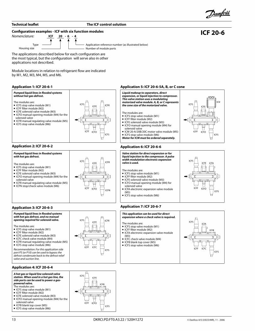
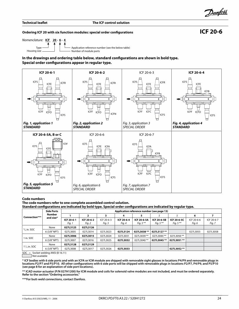
Application 1: ICF 20-6-1Pumped liquid lines in flooded systems without hot gas defrost.
The modules are:l ICFS stop valve module (M1)l ICFF filter module (M�)l ICFE solenoid valve module (M3)l ICFO manual opening module (M4) for the solenoid valvel ICFR manual regulating valve module (M5)l ICFS stop valve module (M6)
Application 2: ICF 20-6-2
Pumped liquid lines in flooded systems with hot gas defrost.The modules are:l ICFS stop valve module (M1)l ICFF filter module (M�)l ICFE solenoid valve module (M3)l ICFO manual opening module (M4) for the solenoid valvel ICFR manual regulating valve module (M5)l ICFN stop/check valve module (M6)
Application 3: ICF 20-6-3Pumped liquid lines in flooded systems with hot gas defrost, and no manual opening required for solenoid valve.
The modules are:l ICFS stop valve module (M1)l ICFF filter module (M�)l ICFE solenoid valve module (M3)l ICFC check valve module (M4)l ICFR manual regulating valve module (M5)l ICFS stop valve module (M6)Recommendation:ForthisapplicationsideportP5(orP10)canbeusedtobypassthedefrostcondensatebacktothedefrostreliefvalveandsuctionline.
Application 4: ICF 20-6-4
A hot gas or liquid line solenoid valve station. When used in a hot gas line, the side ports can be used to power a gas-powered valve.The modules are:l ICFS stop valve module (M1)l ICFF filter module (M�)l ICFE solenoid valve module (M3)l ICFO manual opening module (M4) for the solenoid valvel ICFB blank top cover (M5)l ICFS stop valve module (M6)
Configuration examples - ICF with six function modulesNomenclature: ICF 20 - 6 - 4
TypeNumber of module portsApplication reference number (as illustrated below)
Housing size
Application 5: ICF 20-6-5A, B, or C coneLiquid makeup to separators, direct expansion, or liquid injection to compressor. This valve station uses a modulating motorized valve module. A, B, or C represents the cone size of the motorized valve.
The modules are:l ICFS stop valve module (M1)l ICFF filter module (M�)l ICFE solenoid valve module (M3)l ICFO manual opening module (M4) for solenoid valve l ICM �0-A/�0B/�0C motor valve module (M5)l ICFS stop valve module (M6)Motor for ICM must be ordered separately.
Application 6: ICF 20-6-6
Valve station for direct expansion or for liquid injection to the compressor. A pulse width modulation electronic expansion valve is used.
The modules are:l ICFS stop valve module (M1)l ICFF filter module (M�)l ICFE solenoid valve module (M3)l ICFO manual opening module (M4) for solenoid valve l ICFA electronic expansion valve module (M5)l ICFS stop valve module (M6)
Application 7: ICF 20-6-7
This application can be used for direct expansion where a check valve is required.
The modules are:l ICFS stop valve module (M1)l ICFF filter module (M�)l ICFA electronic expansion valve module (M3)l ICFC check valve module (M4)l ICFB blank top cover (M5)l ICFS stop valve module (M6)
The applications described below for each configuration are the most typical, but the configuration will serve also in other applications not described. Module locations in relation to refrigerant flow are indicated by M1, M�, M3, M4, M5, and M6.
Technical leaflet The ICF control solution
© Danfoss A/S (USCO/MR), 11 - �006 DKRCI.PD.FT0.A3.�� / 5�0H1�7� 14
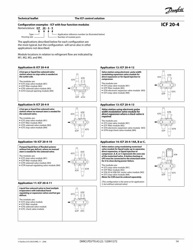
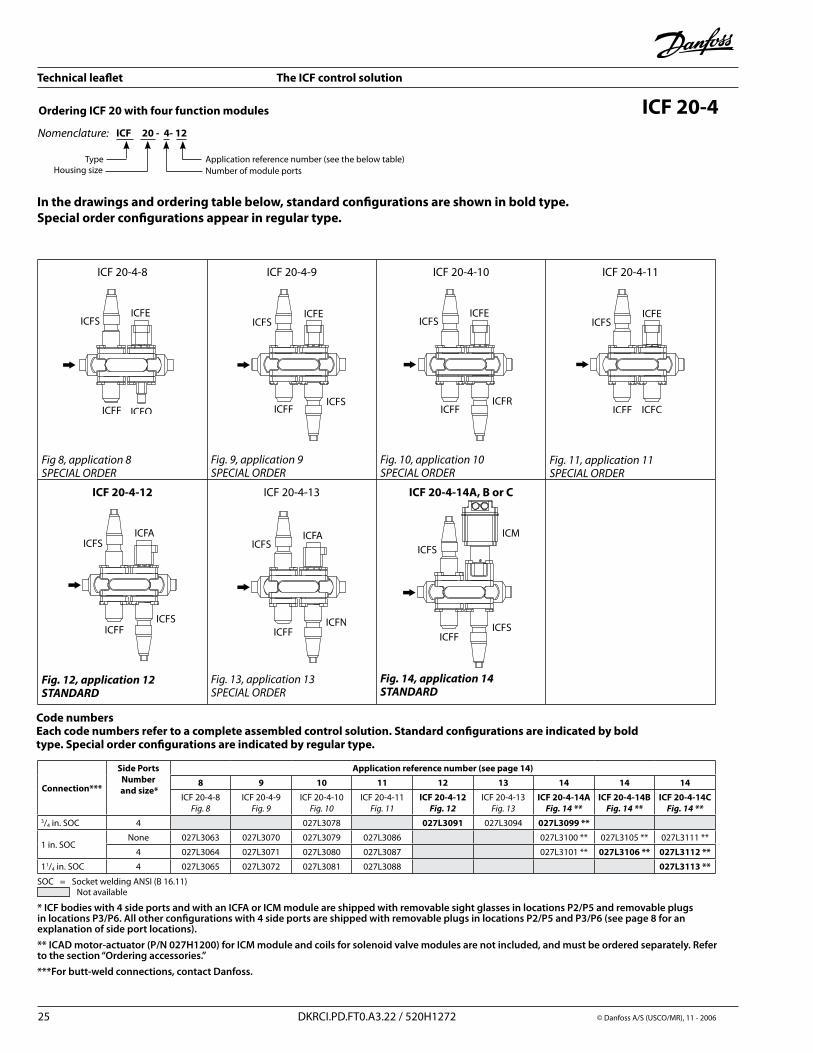
Application 8: ICF 20-4-8A hot gas or liquid line solenoid valve station where no stop valve is needed on the outlet side.
The modules are:l ICFS stop valve module (M1)l ICFF filter module (M�)l ICFE solenoid valve module (M3)l ICFO manual opening module (M4)
Application 9: ICF 20-4-9A hot gas or liquid line solenoid valve station where no manual stem is needed for the solenoid valve.
The modules are:l ICFS stop valve module (M1)l ICFF filter module (M�)l ICFE solenoid valve module (M3)l ICFS stop valve module (M4)
Application 10: ICF 20-4-10
Pumped liquid lines of flooded systems without hot gas defrost, where no manual stem is needed for the solenoid valve.
The modules are:l ICFS stop valve module (M1)l ICFF filter module (M�)l ICFE solenoid valve module (M3)l ICFR manual regulating valve module (M4)
Application 11: ICF 20-4-11
Liquid line solenoid valve to feed multiple evaporators with individual hand regulating or expansion valves and hot gas defrost.
The modules are:l ICFS stop valve modulel ICFF filter modulel ICFE solenoid valve module l ICFC check valve module
Application 12: ICF 20-4-12Valve station using electronic pulse width modulating expansion valve module for direct expansion or for liquid injection to compressor.
The modules are:l ICFS stop valve module (M1)l ICFF filter module (M�)l ICFA electronic expansion valve module (M3)l ICFS stop valve module (M4)
Application 13: ICF 20-4-13
Valve station using electronic pulse width modulation valve module for direct expansion where a check valve is required.
The modules are:l ICFS stop valve module (M1)l ICFF filter module (M�)l ICFA electronic expansion valve module (M3)l ICFN stop/check valve module (M4)
Application 14: ICF 20-4-14A, B or C.
Valve station using modulating motorized valve module for liquid make-up to separator, direct expansion, or liquid injection to compressor. A, B, or C represents the cone size of the motorized valve. A battery backup or UPS must be connected to the motorized valve for it to close during power failure.
The modules are:l ICFS stop valve module (M1)l ICFF filter module (M�)l ICM �0-A/�0B/�0C motor valve module (M3)l ICFS stop valve module (M4)Motor for ICM must be ordered separately.
(Thisconfigurationisthesameasforapplication5,butwithoutsolenoidvalve)
Configuration examples - ICF with four function modulesICF 20 - 4 - 9
TypeNumber of module ports
Nomenclature:
Application reference number (as illustrated below)Housing size
The applications described below for each configuration are the most typical, but the configuration will serve also in other applications not described.
Module locations in relation to refrigerant flow are indicated by M1, M�, M3, and M4.
ICF 20-4
Technical leaflet The ICF control solution
© Danfoss A/S (USCO/MR), 11 - �006 DKRCI.PD.FT0.A3.�� / 5�0H1�7� 15
ICF (25-40)-6
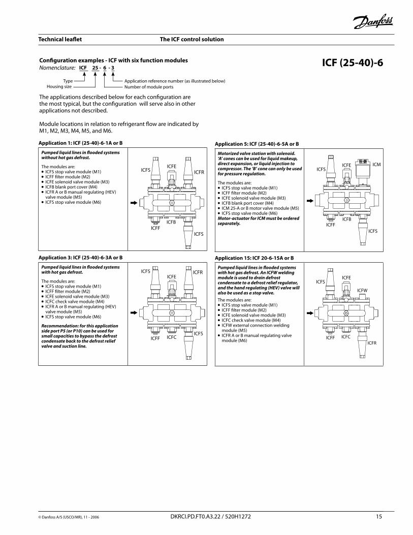
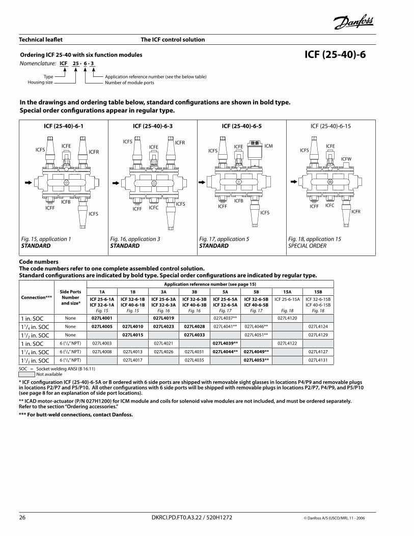
Application 1: ICF (25-40)-6-1A or B
Pumped liquid lines in flooded systems without hot gas defrost.
The modules are:l ICFS stop valve module (M1)l ICFF filter module (M�)l ICFE solenoid valve module (M3)l ICFB blank port cover (M4) l ICFR A or B manual regulating (HEV) valve module (M5)l ICFS stop valve module (M6)
Application 3: ICF (25-40)-6-3A or B
Pumped liquid lines in flooded systems with hot gas defrost.
The modules are:l ICFS stop valve module (M1)l ICFF filter module (M�)l ICFE solenoid valve module (M3)l ICFC check valve module (M4)l ICFR A or B manual regulating (HEV) valve module (M5)l ICFS stop valve module (M6)
Recommendation: for this application side port P5 (or P10) can be used for small capacities to bypass the defrost condensate back to the defrost relief valve and suction line.
Application 5: ICF (25-40)-6-5A or B
Motorized valve station with solenoid. ‘A’ cones can be used for liquid makeup, direct expansion, or liquid injection to compressor. The ‘B’ cone can only be used for pressure regulation.
The modules are:l ICFS stop valve module (M1)l ICFF filter module (M�)l ICFE solenoid valve module (M3)l ICFB blank port cover (M4)l ICM �5-A or B motor valve module (M5)l ICFS stop valve module (M6)Motor-actuator for ICM must be ordered separately.
Application 15: ICF 20-6-15A or B
Pumped liquid lines in flooded systems with hot gas defrost. An ICFW welding module is used to drain defrost condensate to a defrost relief regulator, and the hand regulating (HEV) valve will also be used as a stop valve. The modules are:l ICFS stop valve module (M1)l ICFF filter module (M�)l ICFE solenoid valve module (M3)l ICFC check valve module (M4)l ICFW external connection welding module (M5)l ICFR A or B manual regulating valve module (M6)
ICFBICFB
ICFC
ICFW
ICFR
Configuration examples - ICF with six function modulesICF 25 - 6 - 3
TypeNumber of module ports
Nomenclature:
Application reference number (as illustrated below)Housing size
The applications described below for each configuration are the most typical, but the configuration will serve also in other applications not described.
Module locations in relation to refrigerant flow are indicated by M1, M�, M3, M4, M5, and M6.
Technical leaflet The ICF control solution
© Danfoss A/S (USCO/MR), 11 - �006 DKRCI.PD.FT0.A3.�� / 5�0H1�7� 16
ICF (25-40)-4
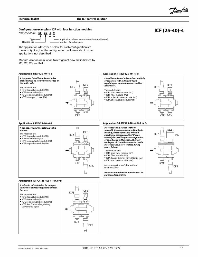
Application 8: ICF (25-40)-4-8
A hot gas or liquid line solenoid valve station where no stop valve is needed on the outlet side)
The modules are:l ICFS stop valve module (M1)l ICFF filter module (M�)l ICFE solenoid valve module (M3)l ICFB blank port cover (M4)
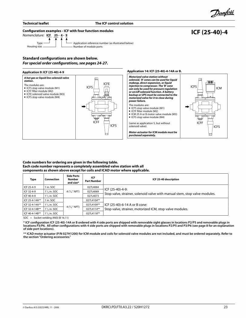
Application 9: ICF (25-40)-4-9
A hot gas or liquid line solenoid valve station .The modules are:l ICFS stop valve module (M1)l ICFF filter module (M�)l ICFE solenoid valve module (M3)l ICFS stop valve module (M4)
Application 10: ICF (25-40)-4-10A or B
A solenoid valve stateion for pumped liquid lines of flooded systems without hot gas.
The modules are:l ICFS stop valve module (M1)l ICFF filter module (M�)l ICFE solenoid valve module (M3)l ICFR A or B manual regulating valve module (M4)
Application 11: ICF (25-40)-4-11
Liquid line solenoid valve to feed multiple evaporators with individual hand regulating or expansion valves and hot gas defrost.
The modules are:l ICFS stop valve module (M1)l ICFF filter module (M�)l ICFE solenoid valve module (M3)l ICFC check valve module (M4)
Application 14: ICF (25-40)-4-14A or B.
Motorized valve station without solenoid. ‘A’ cones can be used for liquid makeup, direct expansion, or liquid injection to compressor. The ‘B’ cone can only be used for pressure regulation or on/off solenoid function. A battery backup or UPS must be connected to the motorized valve for it to close during power failure.The modules are:l ICFS stop valve module (M1)l ICFF filter module (M�)l ICM �5 A or B motor valve module (M3)l ICFS stop valve module (M4)
(same as application 5, but without solenoid valve)
Motor-actuator for ICM module must be purchased separately.
ICFB
Configuration examples - ICF with four function modulesICF 25 - 4 - 9
TypeNumber of module ports
Nomenclature:
Application reference number (as illustrated below)Housing size
The applications described below for each configuration are the most typical, but the configuration will serve also in other applications not described.
Module locations in relation to refrigerant flow are indicated by M1, M�, M3, and M4.
Technical leaflet The ICF control solution
© Danfoss A/S (USCO/MR), 11 - �006 DKRCI.PD.FT0.A3.�� / 5�0H1�7� 17
ICF 20-6-1027L3006
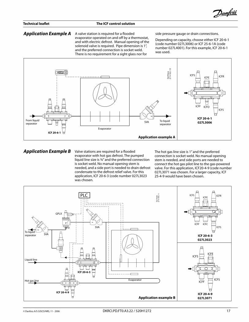
A valve station is required for a flooded evaporator operated on and off by a thermostat, and with electric defrost. Manual opening of the solenoid valve is required. Pipe dimension is 1”, and the preferred connection is socket weld. There is no requirement for a sight glass nor for
Valve stations are required for a flooded evaporator with hot gas defrost. The pumped liquid line size is ¾” and the preferred connection is socket weld. No manual opening stem is needed, and a side port is needed to drain defrost condensate to the defrost relief valve. For this application, ICF �0-6-3 (code number 0�7L30�3 was chosen.
Application Example B
side pressure gauge or drain connections.
Depending on capacity, choose either ICF �0-6-1 (code number 0�7L3006) or ICF �5-6-1A (code number 0�7L4001). For this example, ICF �0-6-1 was used.
Application Example A
To liquid separator
SVA
Evaporator
From liquid separator
ICF 20-6-1
The hot gas line size is 1” and the preferred connection is socket weld. No manual opening stem is needed, and side ports are needed to connect the hot gas pilot line to the gas-powered valve. For this application, ICF�0-4-9 (code number 0�7L3071 was chosen. For a larger capacity, ICF �5-4-9 would have been chosen.
ICF 20-6-3027L3023
ICF 20-4-9027L3071
PLC
GPLX
SVAOFV
SVA
Evaporator
To liquidseparator
Liquid line
Hot gas line
ICF 20-4-9
ICF 20-6-3
Application example B
Application example A
Technical leaflet The ICF control solution
18 DKRCI.PD.FT0.A3.�� / 5�0H1�7� © Danfoss A/S (USCO/MR), 11 - �006
ICF 32-6-5A027L4044
Application example C
To compressor suction line
SVA
SVAAKS 41
SNV
AKS 38
EKC 347
ICF 32-6-5A
From receiver
Wet suction from evaporator
SVASVA
SVASVA
To evaporator
SNV
LLG Recirculator
Application Example D
Application Example C
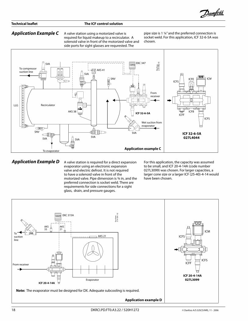
A valve station is required for a direct expansion evaporator using an electronic expansion valve and electric defrost. It is not required to have a solenoid valve in front of the motorized valve. Pipe dimension is ¾ in, and the preferred connection is socket weld. There are requirements for side connections for a sight glass, drain, and pressure gauges.
A valve station using a motorized valve is required for liquid makeup to a recirculator. A solenoid valve in front of the motorized valve and side ports for sight glasses are requrested. The
pipe size is 1 ¼” and the preferred connection is socket weld. For this application, ICF 3�-6-5A was chosen.
For this application, the capacity was assumed to be small, and ICF �0-4-14A (code number 0�7L3099) was chosen. For larger capacities, a larger cone size or a larger ICF (�5-40)-4-14 would have been chosen.
ICF 20-4-14A027L3099
Application example D
EKC 315A
AKS 33
AKS �1
SVAAKS �1
Evaporator
From receiver
To suction line
ICF 20-4-14A
Note: The evaporator must be designed for DX. Adequate subcooling is required.
ICFB
ICFB
Technical leaflet The ICF control solution
© Danfoss A/S (USCO/MR), 11 - �006 DKRCI.PD.FT0.A3.�� / 5�0H1�7� 19
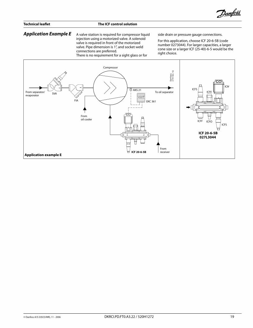
Application Example E A valve station is required for compressor liquid injection using a motorized valve. A solenoid valve is required in front of the motorized valve. Pipe dimension is 1”, and socket weld connections are preferred. There is no requirement for a sight glass or for
ICF 20-6-5B027L3044
Compressor
From separator/evaporator
SVA
FIA
AKS �1
EKC 361
To oil separator
From receiverICF 20-6-5B
From oil cooler
Application example E
side drain or pressure gauge connections.
For this application, choose ICF �0-6-5B (code number 0�73044). For larger capacities, a larger cone size or a larger ICF (�5-40)-6-5 would be the right choice.
Technical leaflet The ICF control solution
© Danfoss A/S (USCO/MR), 11 - �006 DKRCI.PD.FT0.A3.�� / 5�0H1�7� �0
Type Connection Side Ports
Number and size*
ICFPart Number ICF 20 description
ICF �0-6-1
3/4 in. SOC
none
0�7L31�5ICF �0-6-1:Stop valve, strainer, solenoid valve with manual stem, HEV, stop valve modules.
1 in. SOC 0�7L3006
11/4 in. SOC 0�7L31�8
ICF �0-6-�
3/4 in. SOC
none
0�7L31�6 ICF �0-6-�:Stop valve, strainer, solenoid valve with manual stem, HEV, stop/check valve modules.
1 in. SOC 0�7L3015
11/4 in. SOC 0�7L31�9
ICF �0-6-4
3/4 in. SOC
6 (3/8” NPT)
0�7L31�4 ICF �0-6-4:Stop valve, strainer, solenoid valve with manual stem, blank cover, stop valve modules.
1 in. SOC 0�7L303�
11/4 in. SOC 0�7L3033
ICF �0-6-5A ** 3/4 in. SOC 6, (3/8” NPT) 0�7L3038 ** ICF �0-6-5:Stop valve, strainer, solenoid valve with manual stem, motorized ICM, stop valve.Note: ICADmotoractuator(P/N027H1200)forICMmoduleandcoilsarenotincludedandmustbeorderedseparately.Pleaserefertothesection“Orderingaccessories.”
ICF �0-6-5B **3/4 in. SOC
6 (3/8” NPT)0�7L31�7 **
1 in. SOC 0�7L3045 **
ICF �0-6-5C **1 in. SOC
6 (3/8” NPT)0�7L3051 **
11/4 in. SOC 0�7L305� **
Ordering ICF 20 with six function modules
SOC = Socket welding ANSI (B 16.11)
* ICF configuration ICF 20-6-5A, B or C ordered with 6 side ports are shipped with removable sight glasses in locations P4/P9 and removable plugs in locations P2/P7 and P5/P10. All other configurations with 6 side ports will be shipped with removable plugs in locations P2/P7, P4/P9, and P5/P10 (see page 8 for an explanation of side port locations).** ICAD motor actuator (P/N 027H1200) for ICM module and coils for solenoid valve modules are not included, and must be ordered separately. Refer to the section “Ordering accessories.”
ICF 20-6
Code numbers for ordering are given in the following table. Each code number represents a completely assembled valve station with all components as shown above except for coils and ICAD motor where applicable.
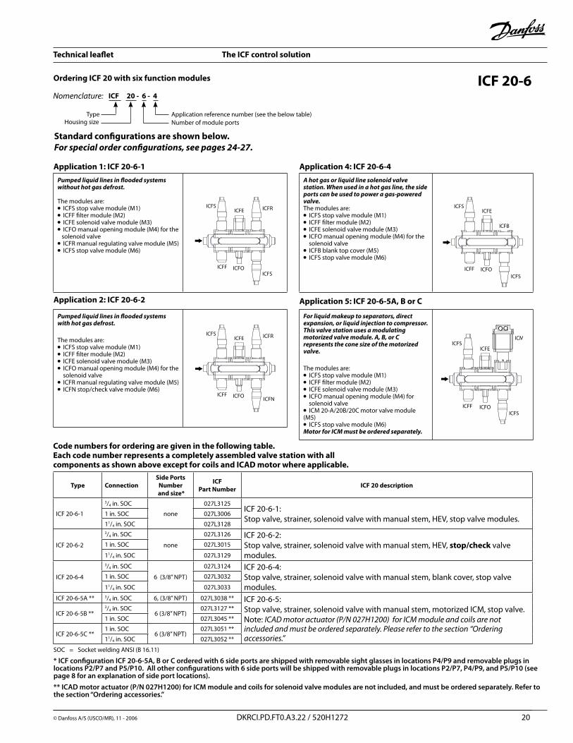
ICF 20 - 6 - 4
TypeNumber of module ports
Nomenclature:
Application reference number (see the below table)Housing size
Application 1: ICF 20-6-1Pumped liquid lines in flooded systems without hot gas defrost.
The modules are:l ICFS stop valve module (M1)l ICFF filter module (M�)l ICFE solenoid valve module (M3)l ICFO manual opening module (M4) for the solenoid valvel ICFR manual regulating valve module (M5)l ICFS stop valve module (M6)
Application 2: ICF 20-6-2
Pumped liquid lines in flooded systems with hot gas defrost.The modules are:l ICFS stop valve module (M1)l ICFF filter module (M�)l ICFE solenoid valve module (M3)l ICFO manual opening module (M4) for the solenoid valvel ICFR manual regulating valve module (M5)l ICFN stop/check valve module (M6)
Application 4: ICF 20-6-4A hot gas or liquid line solenoid valve station. When used in a hot gas line, the side ports can be used to power a gas-powered valve.The modules are:l ICFS stop valve module (M1)l ICFF filter module (M�)l ICFE solenoid valve module (M3)l ICFO manual opening module (M4) for the solenoid valvel ICFB blank top cover (M5)l ICFS stop valve module (M6)
Application 5: ICF 20-6-5A, B or C
For liquid makeup to separators, direct expansion, or liquid injection to compressor. This valve station uses a modulating motorized valve module. A, B, or C represents the cone size of the motorized valve.
The modules are:l ICFS stop valve module (M1)l ICFF filter module (M�)l ICFE solenoid valve module (M3)l ICFO manual opening module (M4) for solenoid valve l ICM �0-A/�0B/�0C motor valve module (M5)l ICFS stop valve module (M6)Motor for ICM must be ordered separately.
Standard configurations are shown below. For special order configurations, see pages 24-27.
Technical leaflet The ICF control solution
© Danfoss A/S (USCO/MR), 11 - �006 DKRCI.PD.FT0.A3.�� / 5�0H1�7� �1
Type Connection Side Ports
Number and size*
ICFPart Number ICF 20 description
ICF �0-4-1� 3/4 in. SOC 4 (3/8” NPT) 0�7L3091ICF �0-4-1�:Stop valve, strainer, electronic expansion valve, stop valve module.
ICF �0-4-14A ** 3/4 in. SOC 4 (3/8” NPT) 0�7L3099 **
ICF �0-4-14:Stop valve, strainer, motorized ICM, stop valve module.Note: ICADandcoilsarenotincludedandmustbeorderedseparately.Pleaserefertothesection“Orderingaccessories.”
ICF �0-4-14B ** 1 in. SOC 4 (3/8” NPT) 0�7L3106 **
ICF �0-4-14C **
1 in. SOC
4 (3/8” NPT)
0�7L311� **
11/4 in. SOC 0�7L3113 **
Ordering ICF 20 with four function modules ICF 20-4
SOC = Socket welding ANSI (B 16.11)
* ICF configurations ICF 20-4-12 and ICF 20-4-14A, B or C ordered with 4 side ports are shipped with removable sight glasses in locations P2/P5 and removable plugs in locations P3/P6 (see page 8 for an explanation of side port locations).** ICAD motor-actuator (P/N 027H1200) for ICM module and coils for solenoid valve modules are not included, and must be ordered separately. Refer to the section “Ordering accessories.”
ICF 20-6-1
Standard configurations are shown below. For special order configurations, see pages 24-27.
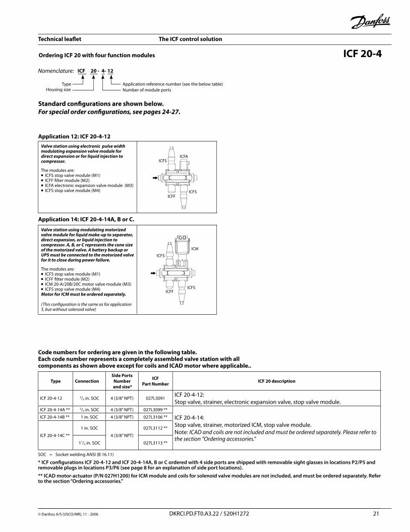
Application 12: ICF 20-4-12Valve station using electronic pulse width modulating expansion valve module for direct expansion or for liquid injection to compressor.
The modules are:l ICFS stop valve module (M1)l ICFF filter module (M�)l ICFA electronic expansion valve module (M3)l ICFS stop valve module (M4)
Application 14: ICF 20-4-14A, B or C.
Valve station using modulating motorized valve module for liquid make-up to separator, direct expansion, or liquid injection to compressor. A, B, or C represents the cone size of the motorized valve. A battery backup or UPS must be connected to the motorized valve for it to close during power failure.
The modules are:l ICFS stop valve module (M1)l ICFF filter module (M�)l ICM �0-A/�0B/�0C motor valve module (M3)l ICFS stop valve module (M4)Motor for ICM must be ordered separately.
(Thisconfigurationisthesameasforapplication5,butwithoutsolenoidvalve)
ICF 20 - 4- 12
TypeNumber of module ports
Nomenclature:
Application reference number (see the below table)Housing size
Code numbers for ordering are given in the following table. Each code number represents a completely assembled valve station with all components as shown above except for coils and ICAD motor where applicable..
Technical leaflet The ICF control solution
© Danfoss A/S (USCO/MR), 11 - �006 DKRCI.PD.FT0.A3.�� / 5�0H1�7� ��
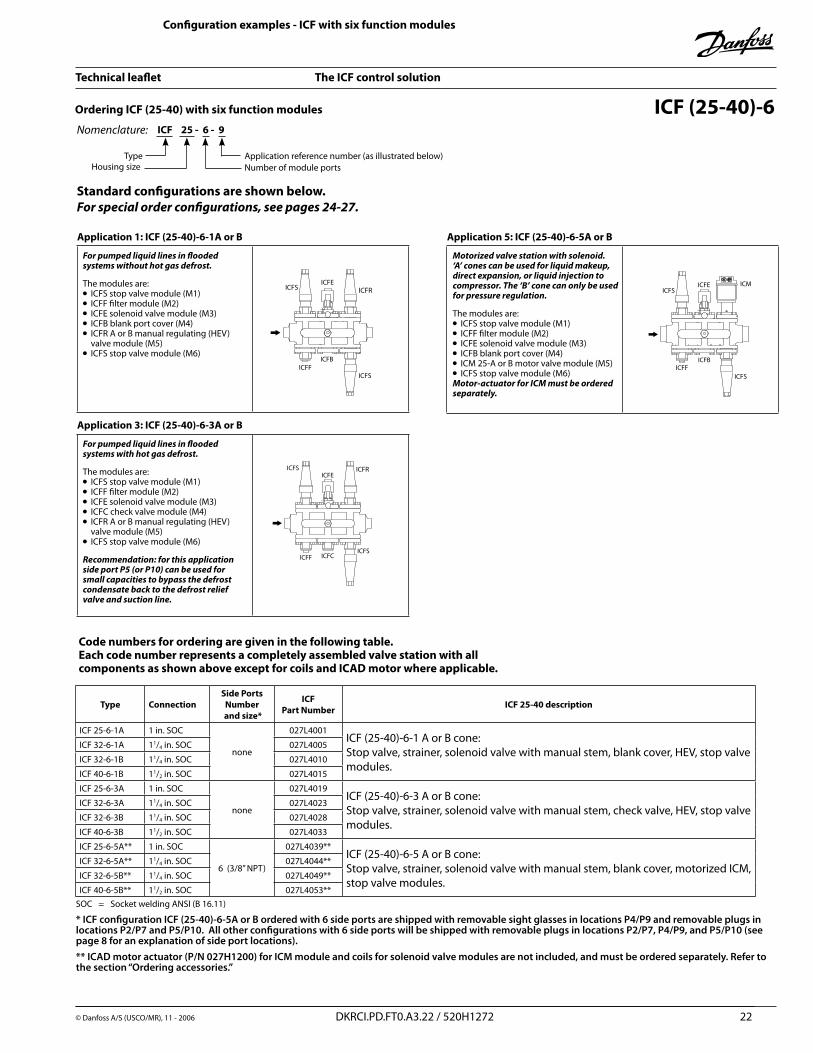
Application 5: ICF (25-40)-6-5A or B
Motorized valve station with solenoid. ‘A’ cones can be used for liquid makeup, direct expansion, or liquid injection to compressor. The ‘B’ cone can only be used for pressure regulation.
The modules are:l ICFS stop valve module (M1)l ICFF filter module (M�)l ICFE solenoid valve module (M3)l ICFB blank port cover (M4)l ICM �5-A or B motor valve module (M5)l ICFS stop valve module (M6)Motor-actuator for ICM must be ordered separately.
ICF (25-40)-6
Application 1: ICF (25-40)-6-1A or B
For pumped liquid lines in flooded systems without hot gas defrost.
The modules are:l ICFS stop valve module (M1)l ICFF filter module (M�)l ICFE solenoid valve module (M3)l ICFB blank port cover (M4) l ICFR A or B manual regulating (HEV) valve module (M5)l ICFS stop valve module (M6)
Application 3: ICF (25-40)-6-3A or B
For pumped liquid lines in flooded systems with hot gas defrost.
The modules are:l ICFS stop valve module (M1)l ICFF filter module (M�)l ICFE solenoid valve module (M3)l ICFC check valve module (M4)l ICFR A or B manual regulating (HEV) valve module (M5)l ICFS stop valve module (M6)
Recommendation: for this application side port P5 (or P10) can be used for small capacities to bypass the defrost condensate back to the defrost relief valve and suction line.
ICFB ICFB
Configuration examples - ICF with six function modules
ICF 25 - 6 - 9
TypeNumber of module ports
Nomenclature:
Application reference number (as illustrated below)Housing size
Type Connection Side Ports
Number and size*
ICFPart Number ICF 25-40 description
ICF �5-6-1A 1 in. SOC
none
0�7L4001ICF (�5-40)-6-1 A or B cone:Stop valve, strainer, solenoid valve with manual stem, blank cover, HEV, stop valve modules.
ICF 3�-6-1A 11/4 in. SOC 0�7L4005
ICF 3�-6-1B 11/4 in. SOC 0�7L4010
ICF 40-6-1B 11/� in. SOC 0�7L4015
ICF �5-6-3A 1 in. SOC
none
0�7L4019ICF (�5-40)-6-3 A or B cone:Stop valve, strainer, solenoid valve with manual stem, check valve, HEV, stop valve modules.
ICF 3�-6-3A 11/4 in. SOC 0�7L40�3
ICF 3�-6-3B 11/4 in. SOC 0�7L40�8
ICF 40-6-3B 11/� in. SOC 0�7L4033
ICF �5-6-5A** 1 in. SOC
6 (3/8” NPT)
0�7L4039**ICF (�5-40)-6-5 A or B cone:Stop valve, strainer, solenoid valve with manual stem, blank cover, motorized ICM, stop valve modules.
ICF 3�-6-5A** 11/4 in. SOC 0�7L4044**
ICF 3�-6-5B** 11/4 in. SOC 0�7L4049**
ICF 40-6-5B** 11/� in. SOC 0�7L4053**SOC = Socket welding ANSI (B 16.11)
* ICF configuration ICF (25-40)-6-5A or B ordered with 6 side ports are shipped with removable sight glasses in locations P4/P9 and removable plugs in locations P2/P7 and P5/P10. All other configurations with 6 side ports will be shipped with removable plugs in locations P2/P7, P4/P9, and P5/P10 (see page 8 for an explanation of side port locations).** ICAD motor actuator (P/N 027H1200) for ICM module and coils for solenoid valve modules are not included, and must be ordered separately. Refer to the section “Ordering accessories.”
Code numbers for ordering are given in the following table. Each code number represents a completely assembled valve station with all components as shown above except for coils and ICAD motor where applicable.
Ordering ICF (25-40) with six function modules
Standard configurations are shown below. For special order configurations, see pages 24-27.
Technical leaflet The ICF control solution
© Danfoss A/S (USCO/MR), 11 - �006 DKRCI.PD.FT0.A3.�� / 5�0H1�7� �3
ICF (25-40)-4
Application 9: ICF (25-40)-4-9
A hot gas or liquid line solenoid valve station .The modules are:l ICFS stop valve module (M1)l ICFF filter module (M�)l ICFE solenoid valve module (M3)l ICFS stop valve module (M4)
Application 14: ICF (25-40)-4-14A or B.
Motorized valve station without solenoid. ‘A’ cones can be used for liquid makeup, direct expansion, or liquid injection to compressor. The ‘B’ cone can only be used for pressure regulation or on/off solenoid function. A battery backup or UPS must be connected to the motorized valve for it to close during power failure.The modules are:l ICFS stop valve module (M1)l ICFF filter module (M�)l ICM �5 A or B motor valve module (M3)l ICFS stop valve module (M4)
(same as application 5, but without solenoid valve)
Motor-actuator for ICM module must be purchased separately.
Configuration examples - ICF with four function modulesICF 25 - 4 - 9
TypeNumber of module ports
Nomenclature:
Application reference number (as illustrated below)Housing size
Standard configurations are shown below. For special order configurations, see pages 24-27.
Type Connection Side Ports
Number and size*
ICFPart Number ICF 25-40 description
ICF �5-4-9 1 in. SOC
4 (3/8 “ NPT)
0�7L4064ICF (�5-40)-4-9:Stop valve, strainer, solenoid valve with manual stem, stop valve modules.
ICF 3�-4-9 11/4 in. SOC 0�7L4069
ICF 40-4-9 11/� in. SOC 0�7L4073
ICF �5-4-14A** 1 in. SOC
4 (3/8 “ NPT)
0�7L4104**
ICF (�5-40)-6-14 A or B cone:Stop valve, strainer, motorized ICM, stop valve modules.
ICF 3�-4-14A** 11/4 in. SOC 0�7L4109**
ICF 3�-4-14B** 11/4 in. SOC 0�7L4114**
ICF 40-4-14B** 11/� in. SOC 0�7L4118**
SOC = Socket welding ANSI (B 16.11)
* ICF configuration ICF (25-40)-14A or B ordered with 4 side ports are shipped with removable sight glasses in locations P2/P5 and removable plugs in locations P3/P6. All other configurations with 4 side ports are shipped with removable plugs in locations P2/P5 and P3/P6 (see page 8 for an explanation of side port locations). ** ICAD motor actuator (P/N 027H1200) for ICM module and coils for solenoid valve modules are not included, and must be ordered separately. Refer to the section “Ordering accessories.”
Code numbers for ordering are given in the following table. Each code number represents a completely assembled valve station with all components as shown above except for coils and ICAD motor where applicable.
Technical leaflet The ICF control solution
© Danfoss A/S (USCO/MR), 11 - �006 DKRCI.PD.FT0.A3.�� / 5�0H1�7� �4
Connection***
Side Ports Number
and size*
Application reference number (see page 13)
1 2 3 4 5 5 5 6 7
ICF 20-6-1Fig.1
ICF 20-6-2Fig.2
ICF �0-6-3Fig.3
ICF 20-6-4Fig.4
ICF 20-6-5AFig.5**
ICF 20-6-5BFig.5**
ICF 20-6-5CFig.5**
ICF �0-6-6Fig.6
ICF �0-6-7Fig.7
3/4 in. SOCNone 027L3125 027L3126
6 (3/8” NPT) 0�7L3005 0�7L3014 0�7L30�3 027L3124 027L3038 ** 027L3127 ** 0�7L3055 0�7L3058
1 in. SOCNone 027L3006 027L3015 0�7L30�4 0�7L3031 0�7L3039 ** 0�7L3044 ** 0�7L3050 **
6 (3/8” NPT) 0�7L3007 0�7L3016 0�7L30�5 027L3032 0�7L3040 ** 027L3045 ** 027L3051 **
11/4 in. SOCNone 027L3128 027L3129
6 (3/8” NPT) 0�7L3008 0�7L3017 0�7L30�6 027L3033 027L3052 **SOC = Socket welding ANSI (B 16.11) Not available
* ICF bodies with 6 side ports and with an ICFA or ICM module are shipped with removable sight glasses in locations P4/P9 and removable plugs in locations P2/P7 and P5/P10. All other configurations with 6 side ports will be shipped with removable plugs in locations P2/P7, P4/P9, and P5/P10 (see page 8 for an explanation of side port locations). ** ICAD motor-actuator (P/N 027H1200) for ICM module and coils for solenoid valve modules are not included, and must be ordered separately. Refer to the section “Ordering accessories.”***For butt-weld connections, contact Danfoss.
Ordering ICF 20 with six function modules: special order configurations ICF 20-6ICF 20 - 6 - 4
TypeNumber of module ports
Nomenclature:
Application reference number (see the below table)Housing size
ICF 20-6-1
Fig. 1, application 1STANDARD
ICF 20-6-2
Fig. 2, application 2STANDARD
ICF �0-6-3
Fig.3,application3SPECIALORDER
ICF 20-6-4
Fig. 4, application 4STANDARD
ICF 20-6-5A, B or C
Fig. 5, application 5STANDARD
ICF �0-6-6
Fig.6,application6SPECIALORDER
ICF �0-6-7
Fig.7,application7SPECIALORDER
In the drawings and ordering table below, standard configurations are shown in bold type. Special order configurations appear in regular type.
Code numbersThe code numbers refer to one complete assembled control solution.Standard configurations are indicated by bold type. Special order configurations are indicated by regular type.
Technical leaflet The ICF control solution
�5 DKRCI.PD.FT0.A3.�� / 5�0H1�7� © Danfoss A/S (USCO/MR), 11 - �006
Ordering ICF 20 with four function modules
ICF �0-4-8
Fig8,application8SPECIALORDER
ICF �0-4-9
Fig.9,application9SPECIALORDER
ICF �0-4-10
Fig.10,application10SPECIALORDER
ICF �0-4-11
Fig.11,application11SPECIALORDER
ICF 20-4-12
Fig. 12, application 12STANDARD
ICF �0-4-13
Fig.13,application13SPECIALORDER
ICF 20-4-14A, B or C
Fig. 14, application 14STANDARD
ICF 20-4ICF 20 - 4- 12
TypeNumber of module ports
Nomenclature:
Application reference number (see the below table)Housing size
In the drawings and ordering table below, standard configurations are shown in bold type. Special order configurations appear in regular type.
SOC = Socket welding ANSI (B 16.11) Not available
* ICF bodies with 4 side ports and with an ICFA or ICM module are shipped with removable sight glasses in locations P2/P5 and removable plugs in locations P3/P6. All other configurations with 4 side ports are shipped with removable plugs in locations P2/P5 and P3/P6 (see page 8 for an explanation of side port locations).** ICAD motor-actuator (P/N 027H1200) for ICM module and coils for solenoid valve modules are not included, and must be ordered separately. Refer to the section “Ordering accessories.”***For butt-weld connections, contact Danfoss.
Connection***
Side Ports Number
and size*
Application reference number (see page 14)
8 9 10 11 12 13 14 14 14
ICF �0-4-8Fig.8
ICF �0-4-9Fig.9
ICF �0-4-10Fig.10
ICF �0-4-11Fig.11
ICF 20-4-12Fig. 12
ICF �0-4-13Fig.13
ICF 20-4-14AFig. 14 **
ICF 20-4-14BFig. 14 **
ICF 20-4-14CFig. 14 **
3/4 in. SOC 4 0�7L3078 027L3091 0�7L3094 027L3099 **
1 in. SOCNone 0�7L3063 0�7L3070 0�7L3079 0�7L3086 0�7L3100 ** 0�7L3105 ** 0�7L3111 **
4 0�7L3064 0�7L3071 0�7L3080 0�7L3087 0�7L3101 ** 027L3106 ** 027L3112 **
11/4 in. SOC 4 0�7L3065 0�7L307� 0�7L3081 0�7L3088 027L3113 **
Code numbersEach code numbers refer to a complete assembled control solution. Standard configurations are indicated by bold type. Special order configurations are indicated by regular type.
Technical leaflet The ICF control solution
�6 DKRCI.PD.FT0.A3.�� / 5�0H1�7� © Danfoss A/S (USCO/MR), 11 - �006
Connection*** Side Ports
Number and size*
Application reference number (see page 15)
1A 1B 3A 3B 5A 5B 15A 15B
ICF 25-6-1AICF 32-6-1A
Fig.15
ICF 32-6-1BICF 40-6-1B
Fig.15
ICF 25-6-3AICF 32-6-3A
Fig.16
ICF 32-6-3BICF 40-6-3B
Fig.16
ICF 25-6-5AICF 32-6-5A
Fig.17
ICF 32-6-5BICF 40-6-5B
Fig.17
ICF �5-6-15A
Fig.18
ICF 3�-6-15BICF 40-6-15B
Fig.18
1 in. SOC None 027L4001 027L4019 0�7L4037** 0�7L41�0
11/4 in. SOC None 027L4005 027L4010 027L4023 027L4028 0�7L4041** 0�7L4046** 0�7L41�4
11/� in. SOC None 027L4015 027L4033 0�7L4051** 0�7L41�9
1 in. SOC 6 (3/8” NPT) 0�7L4003 0�7L40�1 027L4039** 0�7L41��
11/4 in. SOC 6 (3/8” NPT) 0�7L4008 0�7L4013 0�7L40�6 0�7L4031 027L4044** 027L4049** 0�7L41�7
11/� in. SOC 6 (3/8” NPT) 0�7L4017 0�7L4035 027L4053** 0�7L4131
ICF (25-40)-6-1
Fig.15,application1STANDARD
ICF (25-40)-6-3
Fig.16,application3STANDARD
ICF (25-40)-6-5
Fig.17,application5STANDARD
ICF (�5-40)-6-15
Fig.18,application15SPECIALORDER
Ordering ICF 25-40 with six function modulesICF 25 - 6 - 3
TypeNumber of module ports
Nomenclature:
Application reference number (see the below table)Housing size
In the drawings and ordering table below, standard configurations are shown in bold type. Special order configurations appear in regular type.
ICF (25-40)-6
ICFB ICFBICFC
ICFW
ICFR
SOC = Socket welding ANSI (B 16.11) Not available
* ICF configuration ICF (25-40)-6-5A or B ordered with 6 side ports are shipped with removable sight glasses in locations P4/P9 and removable plugs in locations P2/P7 and P5/P10. All other configurations with 6 side ports will be shipped with removable plugs in locations P2/P7, P4/P9, and P5/P10 (see page 8 for an explanation of side port locations).** ICAD motor-actuator (P/N 027H1200) for ICM module and coils for solenoid valve modules are not included, and must be ordered separately. Refer to the section “Ordering accessories.”*** For butt-weld connections, contact Danfoss.
Code numbersThe code numbers refer to one complete assembled control solution.Standard configurations are indicated by bold type. Special order configurations are indicated by regular type.
Technical leaflet The ICF control solution
�7 DKRCI.PD.FT0.A3.�� / 5�0H1�7� © Danfoss A/S (USCO/MR), 11 - �006
ICF 32 - 4- 11
TypeNumber of module ports
Nomenclature:
Application reference number (see the below table)Housing size
Ordering ICF 20 with four function modules
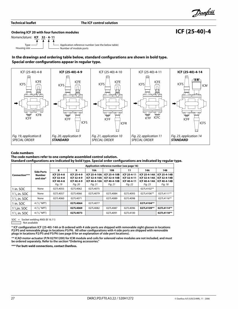
In the drawings and ordering table below, standard configurations are shown in bold type. Special order configurations appear in regular type.
ICF (25-40)-4
ICF (�5-40)-4-8
Fig.19,application8SPECIALORDER
ICF (25-40)-4-9
Fig.20,application9STANDARD
ICF (�5-40)-4-10
Fig.21,application10SPECIALORDER
ICF (�5-40)-4-11
Fig.22,application11SPECIALORDER
ICF (25-40)-4-14
Fig.23,application14STANDARD
ICFB
Connection*** Side Ports
Number and size*
Application reference number (see page 16)
8 9 10A 10B 11 14A 14B
ICF 25-4-8ICF 32-4-8ICF 40-4-8
Fig.19
ICF 25-4-9ICF 32-4-9ICF 40-4-9
Fig.20
ICF 25-4-10AICF 32-4-10AICF 40-4-10A
Fig.21
ICF 25-4-10BICF 32-4-10BICF 40-4-10B
Fig.21
ICF 25-4-11ICF 32-4-11ICF 40-4-11
Fig.22
ICF 25-4-14AICF 32-4-14AICF 40-4-14A
Fig.23
ICF 25-4-14BICF 32-4-14BICF 40-4-14B
Fig.18
1 in. SOC None 0�7L4055 0�7L406� 0�7L4075 0�7L410�**
11/4 in. SOC None 0�7L4057 0�7L4066 0�7L4079 0�7L4084 0�7L4093 0�7L4106** 0�7L4111**
11/� in. SOC None 0�7L4060 0�7L4071 0�7L4089 0�7L4098 0�7L4116**
1 in. SOC 4 (3/8” NPT) 027L4064 0�7L4077 027L4104**
11/4in. SOC 4 (3/8” NPT) 027L4069 0�7L408� 0�7L4087 0�7L4096 027L4109** 027L4114**
11/� in. SOC 4 (3/8” NPT) 027L4073 0�7L4091 0�7L4100 027L4118**
Code numbersThe code numbers refer to one complete assembled control solution.Standard configurations are indicated by bold type. Special order configurations are indicated by regular type.
SOC = Socket welding ANSI (B 16.11) Not available
* ICF configuration ICF (25-40)-14A or B ordered with 4 side ports are shipped with removable sight glasses in locations P2/P5 and removable plugs in locations P3/P6. All other configurations with 4 side ports are shipped with removable plugs in locations P2/P5 and P3/P6 (see page 8 for an explanation of side port locations).
** ICAD motor-actuator (P/N 027H1200) for ICM module and coils for solenoid valve modules are not included, and must be ordered separately. Refer to the section “Ordering accessories.”*** For butt-weld connections, contact Danfoss.
Technical leaflet The ICF control solution
© Danfoss A/S (USCO/MR), 11 - �006 DKRCI.PD.FT0.A3.�� / 5�0H1�7� �8
Quantity Code no.
� 027L1268
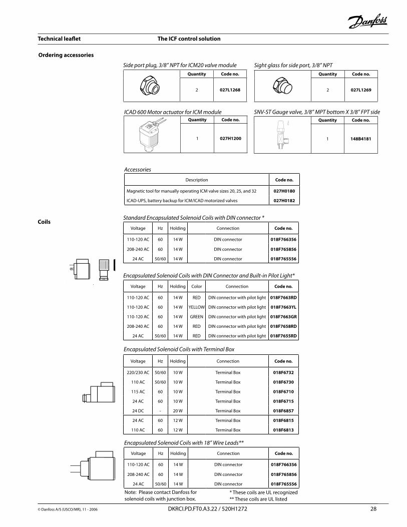
Voltage Hz Holding Connection Code no.
110-1�0 AC 60 14 W DIN connector 018F766356
�08-�40 AC 60 14 W DIN connector 018F765856
�4 AC 50/60 14 W DIN connector 018F765556
Voltage Hz Holding Color Connection Code no.
110-1�0 AC 60 14 W RED DIN connector with pilot light 018F7663RD
110-1�0 AC 60 14 W YELLOW DIN connector with pilot light 018F7663YL
110-1�0 AC 60 14 W GREEN DIN connector with pilot light 018F7663GR
�08-�40 AC 60 14 W RED DIN connector with pilot light 018F7658RD
�4 AC 50/60 14 W RED DIN connector with pilot light 018F7655RD
Voltage Hz Holding Connection Code no.
��0/�30 AC 50/60 10 W Terminal Box 018F6732
110 AC 50/60 10 W Terminal Box 018F6730
115 AC 60 10 W Terminal Box 018F6710
�4 AC 60 10 W Terminal Box 018F6715
�4 DC - �0 W Terminal Box 018F6857
�4 AC 60 1� W Terminal Box 018F6815
110 AC 60 1� W Terminal Box 018F6813
Ordering accessories
Sideportplug,3/8”NPTforICM20valvemoduleQuantity Code no.
� 027L1269
Sightglassforsideport,3/8”NPT
ICAD600MotoractuatorforICMmoduleQuantity Code no.
1 027H1200
CoilsStandardEncapsulatedSolenoidCoilswithDINconnector*
EncapsulatedSolenoidCoilswithDINConnectorandBuilt-inPilotLight*
EncapsulatedSolenoidCoilswithTerminalBox
Quantity Code no.
1 148B4181
SNV-STGaugevalve,3/8”MPTbottomX3/8”FPTside
Voltage Hz Holding Connection Code no.
110-1�0 AC 60 14 W DIN connector 018F766356
�08-�40 AC 60 14 W DIN connector 018F765856
�4 AC 50/60 14 W DIN connector 018F765556
EncapsulatedSolenoidCoilswith18”WireLeads**
Description Code no.
Magnetic tool for manually operating ICM valve sizes �0, �5, and 3� 027H0180
ICAD-UPS, battery backup for ICM/ICAD motorized valves 027H0182
Accessories
* These coils are UL recognized** These coils are UL listed
Note: Please contact Danfoss for solenoid coils with junction box.
Technical leaflet The ICF control solution
�9 DKRCI.PD.FT0.A3.�� / 5�0H1�7� © Danfoss A/S (USCO/MR), 11 - �006
60 m
m(2
.4 in
.)46
mm
(1.8
in.)
292 mm(11.5 in.)
213
mm
(8.4
in.)
176
mm
(6.9
in.)
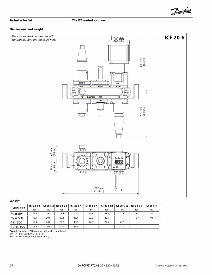
ConnectionICF 20-6-1 ICF 20-6-2 ICF 20-6-3 ICF 20-6-4 ICF 20-6-5A ICF 20-6-5B ICF 20-6-5C ICF 20-6-6 ICF 20-6-7
lbs lbs lbs lbs lbs lbs lbs lbs lbs3/4 in. BW 19.3 19.3 19.6 18.03 �1.8 �1.8 �1.8 18.1 18.3
3/4 in. SOC 19.9 �0.0 �0.� 18.7 ��.5 ��.5 18.7 19.0
1 in. SOC 19.9 �0.0 �0.� 18.7 ��.5 ��.5 ��.5
11/4 in. SOC 19.9 �0.0 �0.� 18.7 ��.5
Dimensions and weight
ICF 20-6
Weight*
*Weight includes ICAD motor-actuator where applicable.BW = Butt-weld ANSI (B 36.10)SOC = Socket welding ANSI (B 16.11)
ThemaximumdimensionsforICFcontrolsolutionsareindicatedhere.
Technical leaflet The ICF control solution
© Danfoss A/S (USCO/MR), 11 - �006 DKRCI.PD.FT0.A3.�� / 5�0H1�7� 30
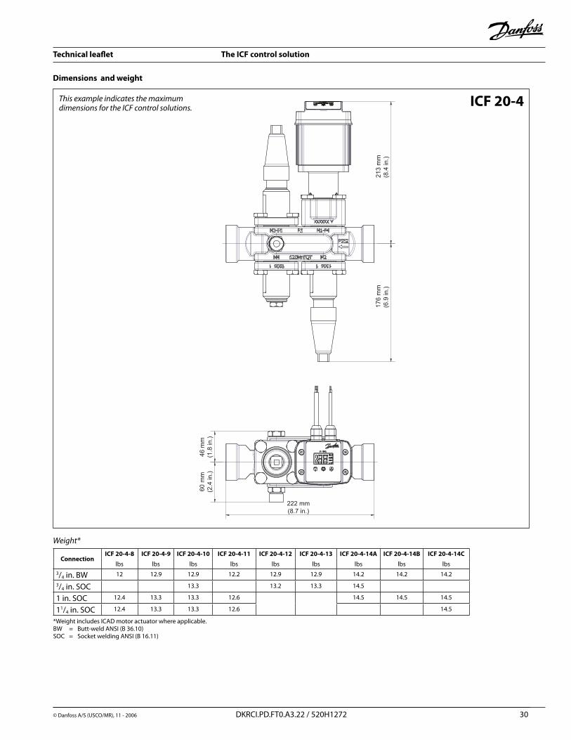
Dimensions and weight
ICF 20-4
ConnectionICF 20-4-8 ICF 20-4-9 ICF 20-4-10 ICF 20-4-11 ICF 20-4-12 ICF 20-4-13 ICF 20-4-14A ICF 20-4-14B ICF 20-4-14C
lbs lbs lbs lbs lbs lbs lbs lbs lbs3/4 in. BW 1� 1�.9 1�.9 1�.� 1�.9 1�.9 14.� 14.� 14.�
3/4 in. SOC 13.3 13.� 13.3 14.5
1 in. SOC 1�.4 13.3 13.3 1�.6 14.5 14.5 14.5
11/4 in. SOC 1�.4 13.3 13.3 1�.6 14.5
213
mm
(8.4
in.)
176
mm
(6.9
in.)
46 m
m(1
.8 in
.)60
mm
(2.4
in.)
222 mm(8.7 in.)
Weight*
ThisexampleindicatesthemaximumdimensionsfortheICFcontrolsolutions.
*Weight includes ICAD motor actuator where applicable.BW = Butt-weld ANSI (B 36.10)SOC = Socket welding ANSI (B 16.11)
Technical leaflet The ICF control solution
31 DKRCI.PD.FT0.A3.�� / 5�0H1�7� © Danfoss A/S (USCO/MR), 11 - �006
Dimensions and weight
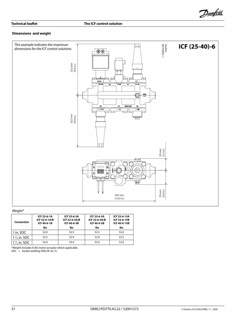
ICF (25-40)-6ThisexampleindicatesthemaximumdimensionsfortheICFcontrolsolutions.
252
mm
(9.9
in.)
252
mm
(9.9
in.)
59 m
m(2
.3 in
.)70
mm
(2.8
in.)
356 mm(14.0 in.)
Danfoss
M27H
0050_1
Connection
ICF 25-6-1AICF 32-6-1A/B
ICF 40-6-1B
ICF 25-6-3AICF 32-6-3A/B
ICF 40-6-3B
ICF 25-6-5AICF 32-6-5A/B
ICF 40-6-5B
ICF 25-6-15A ICF 32-6-15BICF 40-6-15B
lbs lbs lbs lbs
1 in. SOC 5�.0 5�.5 5�.5 5�.0
11/4 in. SOC 5�.5 5�.9 5�.9 5�.5
11/� in. SOC 5�.9 53.4 53.4 5�.9
Weight*
*Weight includes ICAD motor-actuator where applicable.SOC = Socket welding ANSI (B 16.11)
Technical leaflet The ICF control solution
3� DKRCI.PD.FT0.A3.�� / 5�0H1�7� © Danfoss A/S (USCO/MR), 11 - �006
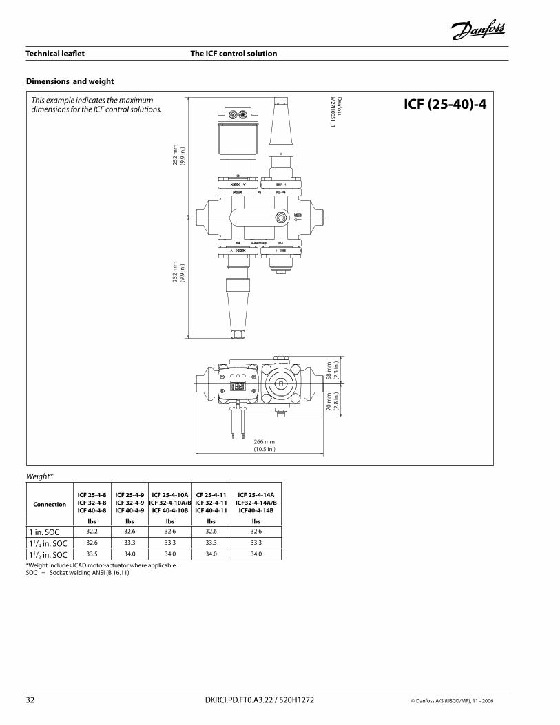
Dimensions and weight
ICF (25-40)-4ThisexampleindicatesthemaximumdimensionsfortheICFcontrolsolutions.
252
mm
(9.9
in.)
Danfoss
M27H
0051_1
252
mm
(9.9
in.)
58 m
m(2
.3 in
.)70
mm
(2.8
in.)
266 mm(10.5 in.)
ConnectionICF 25-4-8ICF 32-4-8 ICF 40-4-8
ICF 25-4-9 ICF 32-4-9 ICF 40-4-9
ICF 25-4-10A ICF 32-4-10A/B
ICF 40-4-10B
CF 25-4-11 ICF 32-4-11 ICF 40-4-11
ICF 25-4-14AICF32-4-14A/B
ICF40-4-14B
lbs lbs lbs lbs lbs
1 in. SOC 3�.� 3�.6 3�.6 3�.6 3�.6
11/4 in. SOC 3�.6 33.3 33.3 33.3 33.3
11/� in. SOC 33.5 34.0 34.0 34.0 34.0
Weight*
*Weight includes ICAD motor-actuator where applicable.SOC = Socket welding ANSI (B 16.11)
Technical leaflet The ICF control solution
© Danfoss A/S (USCO/MR), 11 - �006 DKRCI.PD.FT0.A3.�� / 5�0H1�7� 33
Specifically designed for industrial refrigeration installationsAdvanced and high speed digital stepper motor technologyThree digit seven segment LCD display with three programming keysDegree of valve opening can be observed continuously from actuatorEasily configured on site for different applications (change speed, on-off, modulating valve)Open-close time, ICM-�0: 3seconds Modulating or on-off operationMultiple speed selection during operationAlarm capability, with logging of past alarmsControl input signal : 4-�0 mA, 0-�0 mA, 0-10 V, �-10 VPosition feed back : 0-�0 mA, 4-�0 mA (ICM)3 digit on-off feedbackResolution: �0 microns per step
•
•
•
•
•
•••••
•••
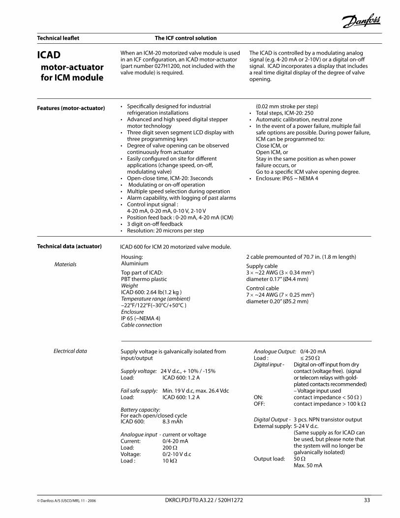
When an ICM-�0 motorized valve module is used in an ICF configuration, an ICAD motor-actuator (part number 0�7H1�00, not included with the valve module) is required.
The ICAD is controlled by a modulating analog signal (e.g. 4-�0 mA or �-10V) or a digital on-off signal. ICAD incorporates a display that includes a real time digital display of the degree of valve opening.
Features (motor-actuator) (0.0� mm stroke per step)Total steps, ICM-�0: �50Automatic calibration, neutral zone In the event of a power failure, multiple fail safe options are possible. During power failure, ICM can be programmed to: Close ICM, or Open ICM, or Stay in the same position as when power failure occurs, or Go to a specific ICM valve opening degree.Enclosure: IP65 ~ NEMA 4
•••
•
ICAD motor-actuator for ICM module
Technical data (actuator) ICAD 600 for ICM �0 motorized valve module. Housing: Aluminium Top part of ICAD: PBT thermo plasticWeight ICAD 600: �.64 lb(1.� kg ) Temperaturerange(ambient) –��°F/1��°F(–30°C/+50°C )Enclosure IP 65 (~NEMA 4)Cableconnection
� cable premounted of 70.7 in. (1.8 m length) Supply cable 3 × ~�� AWG (3 × 0.34 mm�) diameter 0.17” (Ø4.4 mm) Control cable 7 × ~�4 AWG (7 × 0.�5 mm�) diameter 0.�0” (Ø5.� mm)
Supply voltage is galvanically isolated from input/output
Supplyvoltage: �4 V d.c., + 10% / -15%Load: ICAD 600: 1.� A Failsafesupply: Min. 19 V d.c, max. �6.4 VdcLoad: ICAD 600: 1.� A Batterycapacity:For each open/closed cycleICAD 600: 8.3 mAh
Analogueinput-current or voltageCurrent: 0/4-�0 mALoad: �00 WVoltage: 0/�-10 V d.cLoad : 10 kW
AnalogueOutput: 0/4-�0 mALoad : ≤ �50 WDigitalinput - Digital on-off input from dry
contact (voltage free). (signal or telecom relays with gold-plated contacts recommended) – Voltage input used
ON: contact impedance < 50 W )OFF: contact impedance > 100 k W
DigitalOutput - 3 pcs. NPN transistor outputExternal supply: 5-�4 V d.c. (Same supply as for ICAD can be used, but please note that the system will no longer be galvanically isolated)Output load: 50 W Max. 50 mA
Materials
Electricaldata
Technical leaflet The ICF control solution
© Danfoss A/S (USCO/MR), 11 - �006 DKRCI.PD.FT0.A3.�� / 5�0H1�7� 34
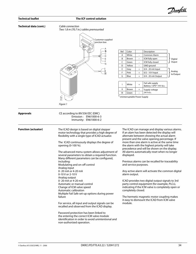
Figure1
Technical data (cont.) CableconnectionTwo1.8m(70.7in.)cablespremounted
Approvals CE according to 89/336 EEC (EMC) Emission : EN61000-6-3 Immunity: EN61000-6-�
Function (actuator) The ICAD design is based on digital stepper motor technology that provides a high degree of flexibility with a single type of ICAD actuator.
The ICAD continuously displays the degree of opening (0-100 %).
The advanced menu system allows adjustment of several parameters to obtain a required function. Many different parameters can be configured, including:Modulating and on-off controlAnalog input 0- �0 mA or 4-�0 mA 0-10 V or �-10 VAnalog output 0- �0 mA or 4-�0 mAAutomatic or manual controlChange of ICM valve speedAutomatic calibrationMultiple Fail Safe set-up options during power failure
For service, all input and output signals can be recalled and observed from the ICAD display.
Password protection has been linked to the entering the correct ICM valve module identification in order to avoid unintentional and non-authorized operation.
The ICAD can manage and display various alarms. If an alam has been detected the display will alternate between showing the actual alarm present and the valve opening percentage. If more than one alarm is active at the same time the alarm with the highest priority will take precedence and will be shown on the display.All alarms automatically reset when no longer displayed.
Previous alarms can be recalled for traceability and service purposes.
Any active alarm will activate the common digital alarm output.
ICAD provides two digital output signals to 3rd party control equipment (for example, PLCs), indicating if the ICM valve is completely open or completely closed.
The hermetic magnetic motor coupling makes it easy to dismount the ICAD from ICM valve module.
Ref. Color Description
A White – Common Alarm
B Brown – ICM fully open
C Green – ICM fully closed
D Yellow – GND ground
E Grey + 0/4 - �0 mA Input
F Pink + 0/� - 10 V Input
G Blue + 0/4 - �0 mA Output
I White + Fail safe supplyBattery / UPS* 19 V d.c.
II Brown + Supply voltage�4 V d.c.III Green –
}}
Digital Ouput
Analog In/Output
* Uninterruptable Power Supply
Customer-suppliedjunction box
Technical leaflet The ICF control solution
© Danfoss A/S (USCO/MR), 11 - �006 DKRCI.PD.FT0.A3.�� / 5�0H1�7� 35
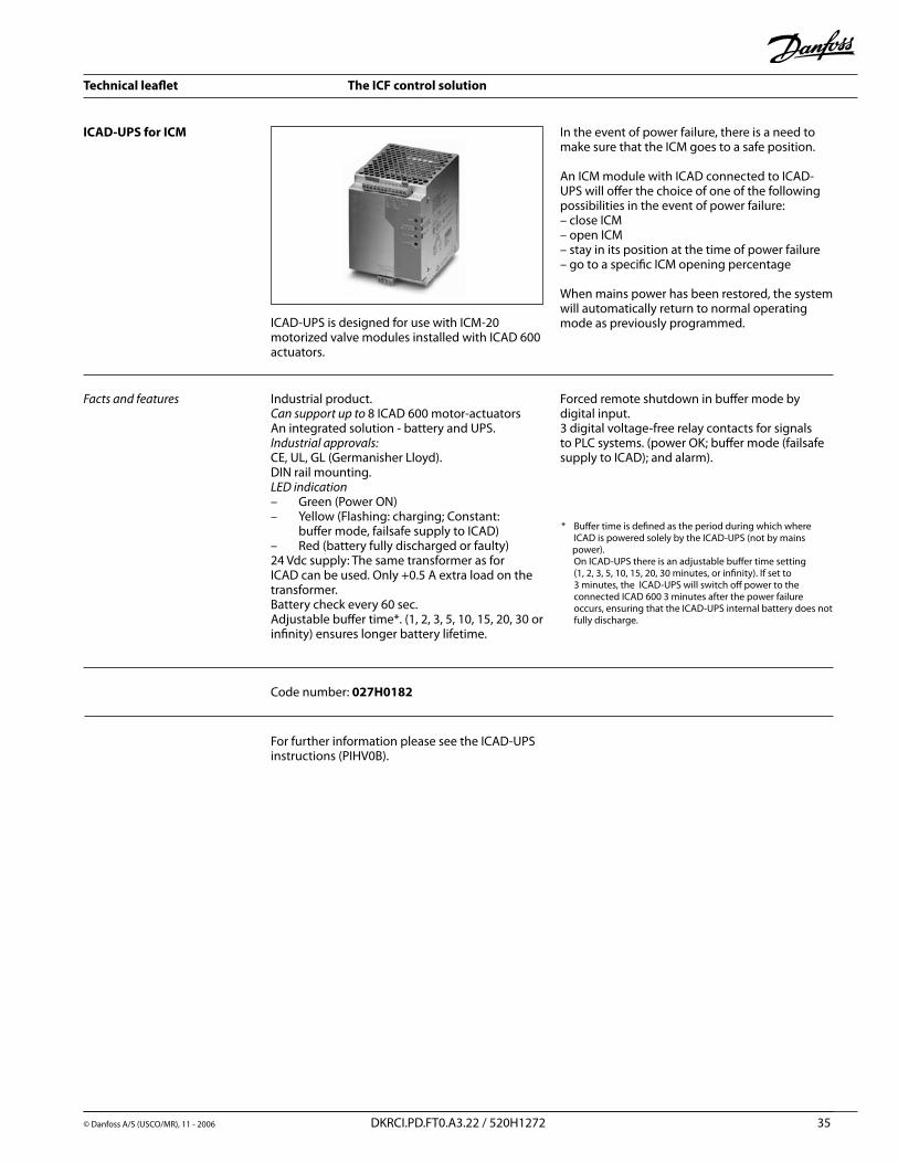
ICAD-UPS for ICM
ICAD-UPS is designed for use with ICM-�0 motorized valve modules installed with ICAD 600 actuators.
In the event of power failure, there is a need to make sure that the ICM goes to a safe position.
An ICM module with ICAD connected to ICAD-UPS will offer the choice of one of the following possibilities in the event of power failure: – close ICM– open ICM– stay in its position at the time of power failure– go to a specific ICM opening percentage
When mains power has been restored, the system will automatically return to normal operating mode as previously programmed.
Factsandfeatures Industrial product.Cansupportupto8 ICAD 600 motor-actuatorsAn integrated solution - battery and UPS.Industrialapprovals: CE, UL, GL (Germanisher Lloyd).DIN rail mounting.LEDindication – Green (Power ON) – Yellow (Flashing: charging; Constant: buffer mode, failsafe supply to ICAD) – Red (battery fully discharged or faulty)�4 Vdc supply: The same transformer as for ICAD can be used. Only +0.5 A extra load on the transformer.Battery check every 60 sec.Adjustable buffer time*. (1, �, 3, 5, 10, 15, �0, 30 or infinity) ensures longer battery lifetime.
Forced remote shutdown in buffer mode by digital input. 3 digital voltage-free relay contacts for signals to PLC systems. (power OK; buffer mode (failsafe supply to ICAD); and alarm).
Code number: 027H0182
For further information please see the ICAD-UPS instructions (PIHV0B).
* Buffer time is defined as the period during which where ICAD is powered solely by the ICAD-UPS (not by mains power). On ICAD-UPS there is an adjustable buffer time setting (1, �, 3, 5, 10, 15, �0, 30 minutes, or infinity). If set to 3 minutes, the ICAD-UPS will switch off power to the connected ICAD 600 3 minutes after the power failure occurs, ensuring that the ICAD-UPS internal battery does not fully discharge.
Technical leaflet The ICF control solution
© Danfoss A/S (USCO/MR), 11 - �006 DKRCI.PD.FT0.A3.�� / 5�0H1�7� 36
ICAD - UPS
Input Output + - + - + - + -
+ -
+ -
max. 5 pcs. of ICAD 900 ormax. 8 pcs. of ICAD 600
ICAD-UPS
Input Output
25 V d.c.0.5 A
24 V d.c.
Whi
te (+
)
Brow
n (+
)
Gre
en (–
)
Whi
te (+
)
Brow
n (+
)
Gre
en (–
)
ICAD UPS
Input Output + - + - + - + -
+ -
max. 5 pcs. of ICAD 900 ormax. 8 pcs. of ICAD 600
ICAD-UPS
Input Output
24 V d.c.
Whi
te (+
)
Brow
n (+
)
Gre
en (–
)
Whi
te (+
)
Brow
n (+
)
Gre
en (–
)
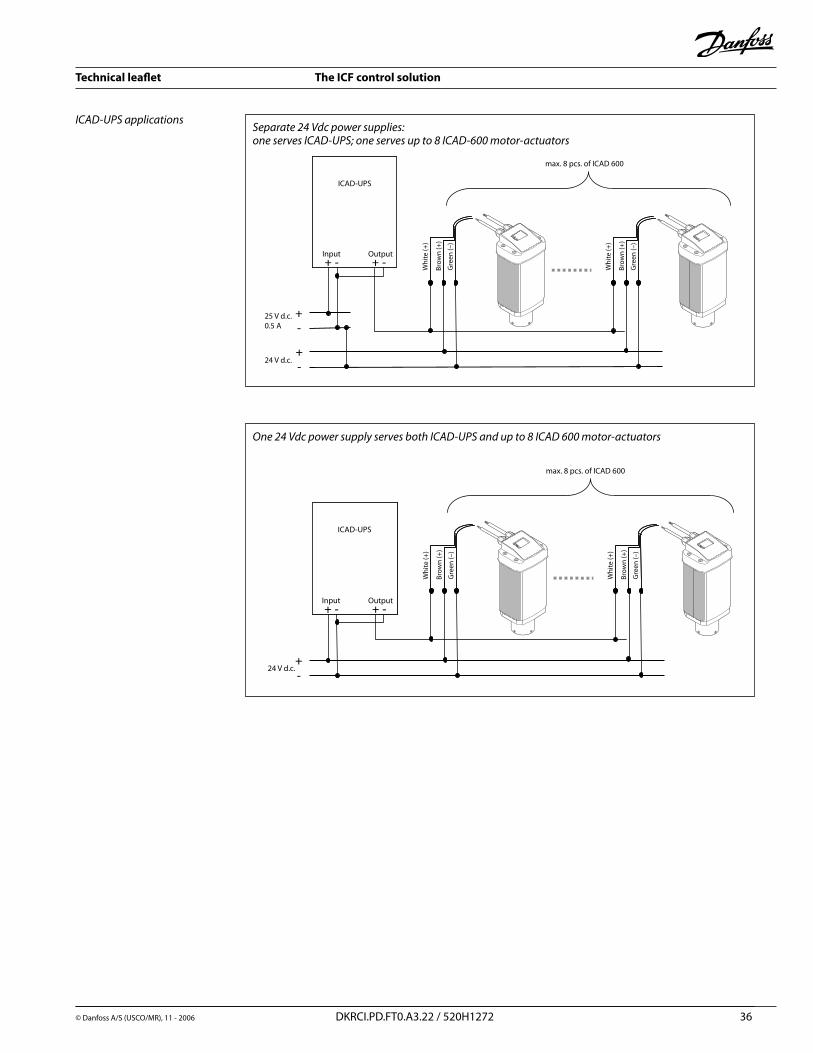
Separate24Vdcpowersupplies:oneservesICAD-UPS;oneservesupto8ICAD-600motor-actuators
One24VdcpowersupplyservesbothICAD-UPSandupto8ICAD600motor-actuators
ICAD-UPSapplications
Technical leaflet The ICF control solution
© Danfoss A/S (USCO/MR), 11 - �006 DKRCI.PD.FT0.A3.�� / 5�0H1�7� 37
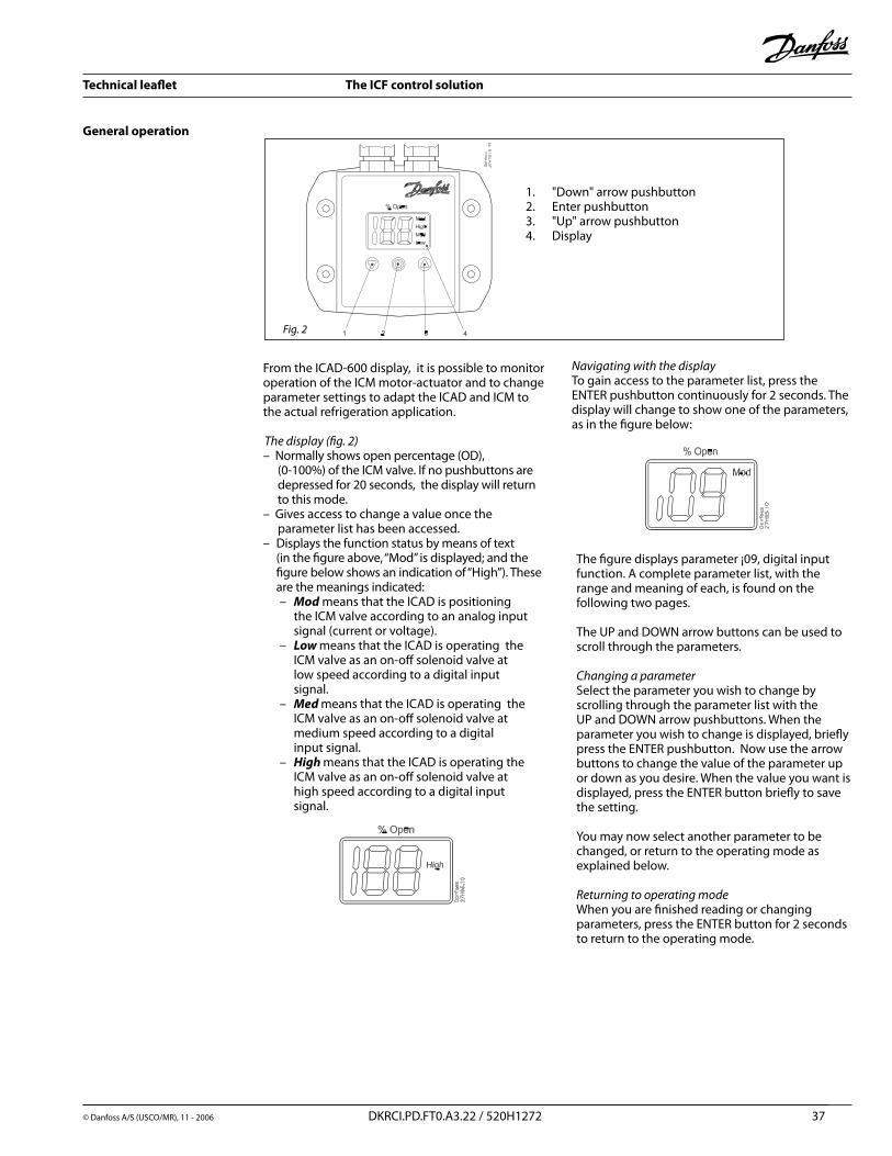
NavigatingwiththedisplayTo gain access to the parameter list, press the ENTER pushbutton continuously for � seconds. The display will change to show one of the parameters, as in the figure below:
The figure displays parameter ¡09, digital input function. A complete parameter list, with the range and meaning of each, is found on the following two pages.
The UP and DOWN arrow buttons can be used to scroll through the parameters.
ChangingaparameterSelect the parameter you wish to change by scrolling through the parameter list with the UP and DOWN arrow pushbuttons. When the parameter you wish to change is displayed, briefly press the ENTER pushbutton. Now use the arrow buttons to change the value of the parameter up or down as you desire. When the value you want is displayed, press the ENTER button briefly to save the setting.
You may now select another parameter to be changed, or return to the operating mode as explained below.
Returningtooperatingmode When you are finished reading or changing parameters, press the ENTER button for � seconds to return to the operating mode.
From the ICAD-600 display, it is possible to monitor operation of the ICM motor-actuator and to change parameter settings to adapt the ICAD and ICM to the actual refrigeration application.
Thedisplay(fig.2)– Normally shows open percentage (OD),
(0-100%) of the ICM valve. If no pushbuttons are depressed for �0 seconds, the display will return to this mode.
– Gives access to change a value once the parameter list has been accessed.
– Displays the function status by means of text (in the figure above, “Mod” is displayed; and the figure below shows an indication of “High”). These are the meanings indicated:– Mod means that the ICAD is positioning the ICM valve according to an analog input signal (current or voltage).– Low means that the ICAD is operating the ICM valve as an on-off solenoid valve at low speed according to a digital input signal.– Med means that the ICAD is operating the ICM valve as an on-off solenoid valve at medium speed according to a digital input signal.– High means that the ICAD is operating the ICM valve as an on-off solenoid valve at high speed according to a digital input signal.
General operation
1. "Down" arrow pushbutton�. Enter pushbutton3. "Up" arrow pushbutton4. Display
Fig.2
"Down"arrow Enter "Up"arrow
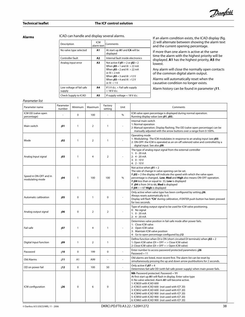
Technical leaflet The ICF control solution
© Danfoss A/S (USCO/MR), 11 - �006 DKRCI.PD.FT0.A3.�� / 5�0H1�7� 38
Parameterlist
Parameter name Parameter number Minimum Maximum Factory
setting Unit Comments
ICM OD (valve open percentage) - 0 100 - % ICM valve open percentage is displayed during normal operation.
Running display value (see ¡01, ¡05).
Main switch ¡01 1 � 1 -
Internal main switch1: Normal operation�: Manual operation. Display flashing. The OD (valve open percentage) can be
manually adjusted with the arrow buttons over a range from 0-100%.
Mode ¡02 1 � 1 -
Operating mode1: Modulating: The ICM modulates in response to an analog input (see ¡03)�: ON-OFF: the ICM is operated as an on-off solenoid valve and controlled by a
digital input. See also ¡09.
Analog Input signal ¡03 1 4 � -
The type of analog input signal from the external controller1: 0 - �0 mA�: 4 - �0 mA3: 0 - 10 V4: � - 10 V
Speed in ON-OFF and in modulating mode ¡04 1 100 100 %
Not active when ¡01 = �The rate of change in valve opening can be set.If ¡02 = � the display will indicate the speed with which the valve open percentage is changed.. Low, Med and High also means ON-OFF operation.If ¡04 less than or equal to 33, Low is displayedIf ¡04 is from 34 to 66, Med is displayedIf ¡04 > = 67 High is displayed
Automatic calibration ¡05 0 1 0 -
Only active when valve type has been configured by setting ¡26.Always resets automatically to 0.Display will flash “CA” during calibration, if ENTER push button has been pressed for two seconds.
Analog output signal ¡06 0 � � -
Type of analog output signal to be used for ICM valve positioning.0: No signal1: 0 - �0 mA�: 4 - �0 mA
Fail safe ¡07 1 4 1 -
Determines valve position in fail-safe mode after power fails.1: Close ICM valve�: Open ICM valve3: Maintain ICM valve position4: Go to open percentage configured by ¡12
Digital Input function ¡09 1 � 1Define function when DI is ON (short circuited DI terminals) when ¡02 = �1: Open ICM valve (DI = OFF = > Close ICM valve)�: Close ICM valve (DI = OFF = > Open ICM valve)
Password ¡10 0 199 0 - Enter number to access password protected parameters: ¡26Password = 11
Old Alarms ¡11 A1 A99 - - Old alarms are listed, most recent first. The alarm list can be reset by simultaneously pressing the up and down arrow pushbuttons for � seconds.
OD on power fail ¡12 0 100 50 - Only active if ¡07 = 4Determines fail safe OD (with fail-safe power supply) when main power fails.
ICM configuration ¡26 0 6 0
NB: Password protected. Password = 11At first start up A1 will flash in display. Enter valve type0: No valve selected. Alarm A1 will become active.1: ICM�0 with ICAD 600�: ICM�5 with ICAD 600 (not used with ICF �0)3: ICM3� with ICAD 600 (not used with ICF �0)4: ICM40 with ICAD 900 (not used with ICF �0) 5: ICM50 with ICAD 900 (not used with ICF �0)6: ICM65 with ICAD 900 (not used with ICF �0)
ICAD can handle and display several alarms.
Description ICMalarm text Comments
No valve type selected A1 At start-up A1 and CA will be displayed
Controller fault A2 Internal fault inside electronics
Analog input error A3 Not active if ¡01 = � or ¡02 = �When ¡03 = 1 and AI > �� mAWhen ¡03 = � and AI > �� mAor AI < � mAWhen ¡03 = 3 and AI >1� VWhen ¡03 = 4 and AI >1� Vor AI < 1 V
Low voltage of fail safe supply
A4 If 5 V d.c. < Fail safe supply < 18 V d.c.
Check Supply to ICAD A5 If supply voltage < 18 V d.c.
Alarms If an alarm condition exists, the ICAD display (fig. �) will alternate between showing the alarm text and the current opening percentage.
If more than one alarm is active at the same time the alarm with the highest priority will be displayed. A1 has the highest priority, A5 the lowest.
Any alarm will close the normally open contacts of the common digital alarm output.
Alarms will automatically reset when the causative condition no longer exists.
Alarm history can be found in parameter ¡11.
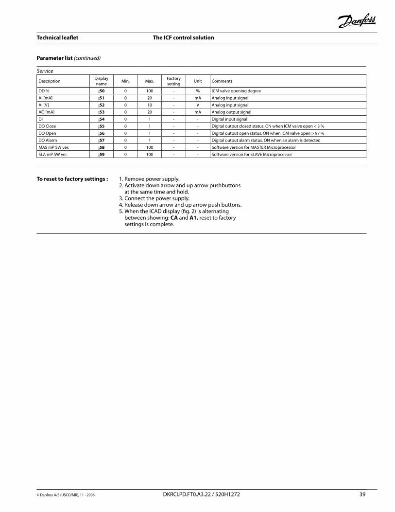
Technical leaflet The ICF control solution
© Danfoss A/S (USCO/MR), 11 - �006 DKRCI.PD.FT0.A3.�� / 5�0H1�7� 39
Parameter list (continued)
To reset to factory settings : 1. Remove power supply.�. Activate down arrow and up arrow pushbuttons
at the same time and hold.3. Connect the power supply.4. Release down arrow and up arrow push buttons.5. When the ICAD display (fig. �) is alternating
between showing: CA and A1, reset to factory settings is complete.
Service
Description Display name Min. Max. Factory
setting Unit Comments
OD % ¡50 0 100 - % ICM valve opening degree
AI [mA] ¡51 0 �0 - mA Analog input signal
AI [V] ¡52 0 10 - V Analog input signal
AO [mA] ¡53 0 �0 - mA Analog output signal
DI ¡54 0 1 - - Digital input signal
DO Close ¡55 0 1 - - Digital output closed status. ON when ICM valve open < 3 %
DO Open ¡56 0 1 - - Digital output open status. ON when ICM valve open > 97 %
DO Alarm ¡57 0 1 - - Digital output alarm status. ON when an alarm is detected
MAS mP SW ver. ¡58 0 100 - - Software version for MASTER Microprocessor
SLA mP SW ver. ¡59 0 100 - - Software version for SLAVE Microprocessor
Technical leaflet The ICF control solution
40 DKRCI.PD.FT0.A3.�� / 5�0H1�7� © Danfoss A/S (USCO/MR), 11 - �006
Danfoss · Refrigeration & Air Conditioning Division · 7941 Corporate Drive · Baltimore, MD �1�36Ph 410-931-8�50 · Fax 410-931-8�56 · E-mail: [email protected] · Internet: www.danfoss.com/North_America
![ICF-M770L/M770S/M770SL - Kazenice.kaze.com/sony_icf-m770sl_svm.pdf · ICF-M770L/M770S/M770SL no mark: common (): ICF-M770L []: ICF-M770S 〈〈 〉〉: ICF-M770SL AM IF ADJUSTMENT](https://img.pdfslide.us/doc/110x75/5f05960a7e708231d413b21e/icf-m770lm770sm770sl-icf-m770lm770sm770sl-no-mark-common-icf-m770l-.jpg)