Embed Size (px)
Citation preview
Quick Selection Guide
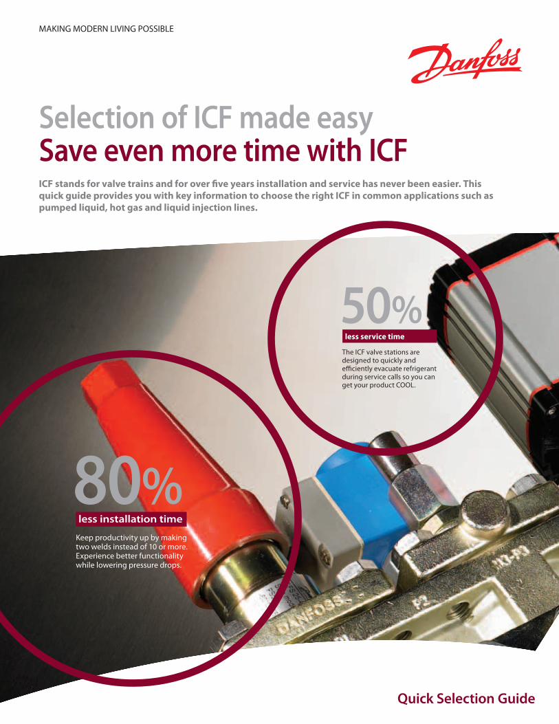
50%The ICF valve stations are designed to quickly and efficiently evacuate refrigerant during service calls so you can get your product COOL.
80%less installation time
Keep productivity up by making two welds instead of 10 or more.Experience better functionality while lowering pressure drops.
less service time
Selection of ICF made easySave even more time with ICFICF stands for valve trains and for over five years installation and service has never been easier. This quick guide provides you with key information to choose the right ICF in common applications such as pumped liquid, hot gas and liquid injection lines.
MAKING MODERN LIVING POSSIBLE
Produced by ©Metaphor, 01-2011
Application Guide ICF Valve Station
3DKRCI.PA.FT0.A1.22 / 520H5093Produced by ©Metaphor, 01-2011
Approvals. . . . . . . . . . . . . . . . . . . . . . . . . . . . . . . . . . . . . . . . . . . . . . . . . . . . . . . . . . . . . . . . . . . . . . . . . . . . . . . . . . . . . . . . . . . . . . . . . 5Technical data. . . . . . . . . . . . . . . . . . . . . . . . . . . . . . . . . . . . . . . . . . . . . . . . . . . . . . . . . . . . . . . . . . . . . . . . . . . . . . . . . . . . . . . . . . . . . 5ICF in detail . . . . . . . . . . . . . . . . . . . . . . . . . . . . . . . . . . . . . . . . . . . . . . . . . . . . . . . . . . . . . . . . . . . . . . . . . . . . . . . . . . . . . . . . . . . . . . . 6Flow through the ICF . . . . . . . . . . . . . . . . . . . . . . . . . . . . . . . . . . . . . . . . . . . . . . . . . . . . . . . . . . . . . . . . . . . . . . . . . . . . . . . . . . . . . . 6ICF overview . . . . . . . . . . . . . . . . . . . . . . . . . . . . . . . . . . . . . . . . . . . . . . . . . . . . . . . . . . . . . . . . . . . . . . . . . . . . . . . . . . . . . . . . . . . . . . 6Design work with ICF . . . . . . . . . . . . . . . . . . . . . . . . . . . . . . . . . . . . . . . . . . . . . . . . . . . . . . . . . . . . . . . . . . . . . . . . . . . . . . . . . . . . . . 8
Standard applications . . . . . . . . . . . . . . . . . . . . . . . . . . . . . . . . . . . . . . . . . . . . . . . . . . . . . . . . . . . . . . . . . . . . . . . . . . . . . . . . . . . . . 9Pumped liquid line . . . . . . . . . . . . . . . . . . . . . . . . . . . . . . . . . . . . . . . . . . . . . . . . . . . . . . . . . . . . . . . . . . . . . . . . . . . . . . . . . . . .10Hot gas defrost. . . . . . . . . . . . . . . . . . . . . . . . . . . . . . . . . . . . . . . . . . . . . . . . . . . . . . . . . . . . . . . . . . . . . . . . . . . . . . . . . . . . . . . .11Liquid injection to separator . . . . . . . . . . . . . . . . . . . . . . . . . . . . . . . . . . . . . . . . . . . . . . . . . . . . . . . . . . . . . . . . . . . . . . . . . . .12
Accessories for ICF. . . . . . . . . . . . . . . . . . . . . . . . . . . . . . . . . . . . . . . . . . . . . . . . . . . . . . . . . . . . . . . . . . . . . . . . . . . . . . . . . . . . . . . .13

Produced by ©Metaphor, 01-2011
Application Guide ICF Valve Station
5DKRCI.PA.FT0.A1.22 / 520H5093Produced by ©Metaphor, 01-2011
Refrigerants Applicable to all common non flammable refrigerants including R717, R744 (CO2) and non corrosive gases/liquids dependent on sealing material compatibility. For further information please refer to installation instruction for ICF. Use of the ICF control solution with flammable hydrocarbons is not recommended. For further information please contact the local Danfoss sales company.Temperature range –60/+120°C (–76/+248°F).
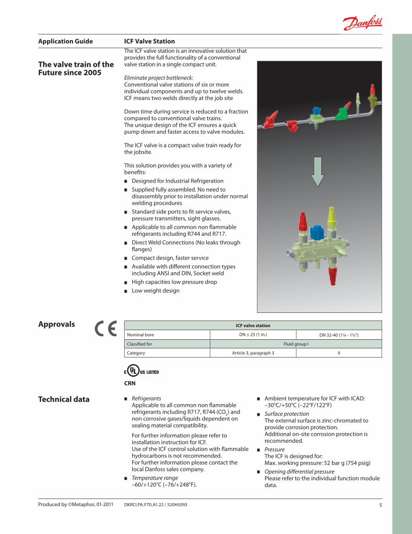
The valve train of the Future since 2005
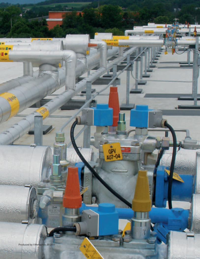
The ICF valve station is an innovative solution that provides the full functionality of a conventional valve station in a single compact unit.
Eliminate project bottleneck:Conventional valve stations of six or more individual components and up to twelve welds. ICF means two welds directly at the job site
Down time during service is reduced to a fraction compared to conventional valve trains. The unique design of the ICF ensures a quick pump down and faster access to valve modules.
The ICF valve is a compact valve train ready for the jobsite.
This solution provides you with a variety of benefits:
Designed for Industrial RefrigerationSupplied fully assembled. No need to disassembly prior to installation under normal welding proceduresStandard side ports to fit service valves, pressure transmitters, sight glasses.Applicable to all common non flammable refrigerants including R744 and R717.Direct Weld Connections (No leaks through flanges)Compact design, faster serviceAvailable with different connection types including ANSI and DIN, Socket weldHigh capacities low pressure dropLow weight design
Approvals ICF valve station
Nominal bore DN ≤ 25 (1 in.) DN 32-40 (1¼ - 1½”)
Classified for Fluid group I
Category Article 3, paragraph 3 II
Technical data Ambient temperature for ICF with ICAD: –30°C/+50°C (–22°F/122°F)Surface protection The external surface is zinc-chromated to provide corrosion protection. Additional on-site corrosion protection is recommended.Pressure The ICF is designed for: Max. working pressure: 52 bar g (754 psig)Opening differential pressure Please refer to the individual function module data.
CRN
Application Guide ICF Valve Station
6 DKRCI.PA.FT0.A1.22 / 520H5093 Produced by ©Metaphor, 01-2011
ICF 20-4 ICF 20-6 ICF (25-40)-4 ICF (25-40)-6
M1
M2
M3
M4
M1
M2
M3
M4
M5
M6
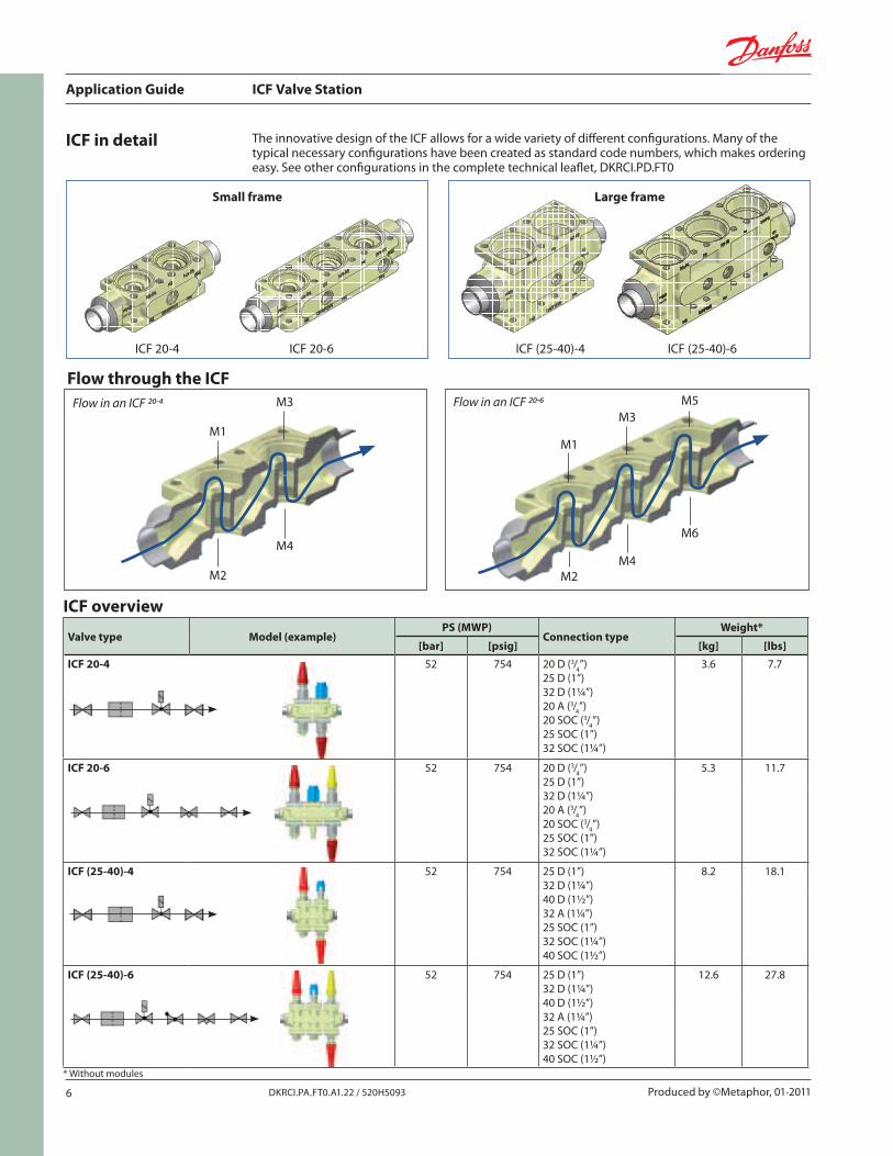
ICF in detail The innovative design of the ICF allows for a wide variety of different configurations. Many of the typical necessary configurations have been created as standard code numbers, which makes ordering easy. See other configurations in the complete technical leaflet, DKRCI.PD.FT0
Flow in an ICF 20-4 Flow in an ICF 20-6
Small frame Large frame
Flow through the ICF
ICF overview
Valve type Model (example)PS (MWP)
Connection typeWeight*
[bar] [psig] [kg] [lbs]ICF 20-4 52 754 20 D (3/4”)
25 D (1”)32 D (1¼”)20 A (3/4”)20 SOC (3/4”)25 SOC (1”)32 SOC (1¼”)
3.6 7.7
ICF 20-6 52 754 20 D (3/4”)25 D (1”)32 D (1¼”)20 A (3/4”)20 SOC (3/4”)25 SOC (1”)32 SOC (1¼”)
5.3 11.7
ICF (25-40)-4 52 754 25 D (1”)32 D (1¼”)40 D (1½”)32 A (1¼”)25 SOC (1”)32 SOC (1¼”)40 SOC (1½”)
8.2 18.1
ICF (25-40)-6 52 754 25 D (1”)32 D (1¼”)40 D (1½”)32 A (1¼”)25 SOC (1”)32 SOC (1¼”)40 SOC (1½”)
12.6 27.8
* Without modules
Application Guide ICF Valve Station
7DKRCI.PA.FT0.A1.22 / 520H5093Produced by ©Metaphor, 01-2011
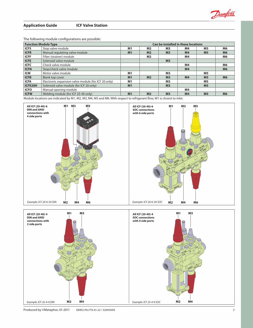
Function Module Type Can be installed in these locationsICFS Stop valve module M1 M2 M3 M4 M5 M6ICFR Manual regulating valve module M1 M2 M3 M4 M5 M6ICFF Filter (strainer) module M2 M4 M6ICFE Solenoid valve module M3ICFC Check valve module M4 M6ICFN Stop/check valve module M4 M6ICM Motor valve module M1 M3 M5ICFB Blank top cover M1 M2 M3 M4 M5 M6ICFA Electronic expansion valve module (for ICF 20 only) M1 M3 M5ICFE20H Solenoid valve module (for ICF 20 only) M1 M3 M5ICFO Manual opening module M4ICFW Welding module (for ICF 25-40 only) M1 M2 M3 M4 M5 M6
Module locations are indicated by M1, M2, M3, M4, M5 and M6. With respect to refrigerant flow, M1 is closest to inlet.
The following module configurations are possible:
Example: ICF 20-6-5A DIN Example: ICF 20-6-2H SOC
Example: ICF 25-4-9 DIN Example: ICF 25-4-9 SOC
All ICF (20-40)-6 DIN and ANSI connections with 4 side ports
All ICF (20-40)-6 SOC connections with 6 side ports
All ICF (20-40)-4 SOC connections with 4 side ports
All ICF (20-40)-4 DIN and ANSI connections with 2 side ports
Application Guide ICF Valve Station
8 DKRCI.PA.FT0.A1.22 / 520H5093 Produced by ©Metaphor, 01-2011
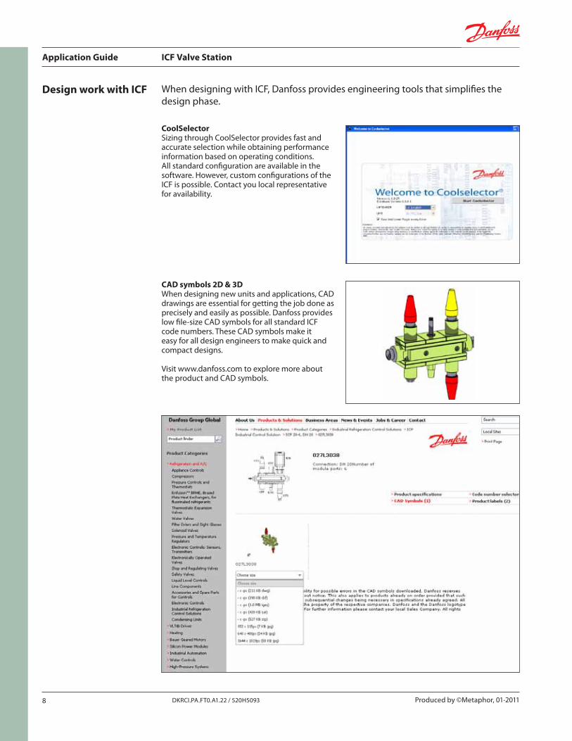
Design work with ICF When designing with ICF, Danfoss provides engineering tools that simplifies the design phase.
CoolSelectorSizing through CoolSelector provides fast and accurate selection while obtaining performance information based on operating conditions.All standard configuration are available in the software. However, custom configurations of the ICF is possible. Contact you local representative for availability.
CAD symbols 2D & 3DWhen designing new units and applications, CAD drawings are essential for getting the job done as precisely and easily as possible. Danfoss provides low file-size CAD symbols for all standard ICF code numbers. These CAD symbols make it easy for all design engineers to make quick and compact designs.
Visit www.danfoss.com to explore more about the product and CAD symbols.
Application Guide ICF Valve Station
9DKRCI.PA.FT0.A1.22 / 520H5093Produced by ©Metaphor, 01-2011
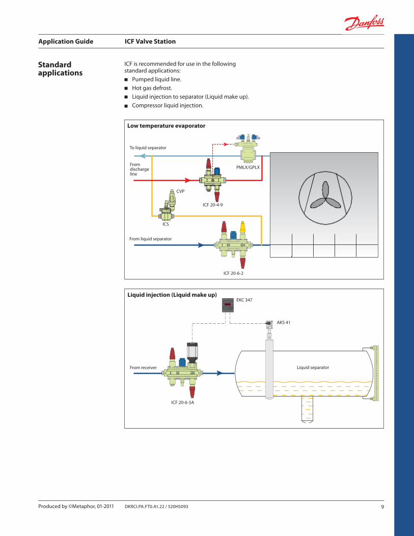
ICF 20-4-9
ICF 20-6-2
PMLX/GPLX
ICS
ICF 20-6-5A
AKS 41
CVP
EKC 347
Standard applications
ICF is recommended for use in the following standard applications:
Pumped liquid line.Hot gas defrost.Liquid injection to separator (Liquid make up).Compressor liquid injection.
Low temperature evaporator
To liquid separator
From discharge line
From liquid separator
Liquid injection (Liquid make up)
From receiver Liquid separator
Application Guide ICF Valve Station
10 DKRCI.PA.FT0.A1.22 / 520H5093 Produced by ©Metaphor, 01-2011
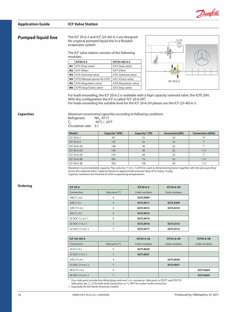
ICF 20-6-2
Pumped liquid line The ICF 20-6-2 and ICF (25-40)-6-3 are designed for a typical pumped liquid line in a flooded evaporator system.
The ICF valve station consists of the following modules:
ICF20-6-2 ICF(25-40)-6-3
M1 ICFS (Stop valve) ICFS (Stop valve)
M2 ICFF (Filter) ICFF (Filter)
M3 ICFE (Solenoid valve) ICFE (Solenoid valve)
M4 ICFO (Manual opener for ICFE) ICFC (Check valve)
M5 ICFR (Regulation valve) ICFR (Regulation valve)
M6 ICFN (Stop/Check valve) ICFS (Stop valve)
For loads exceeding, the ICF 20-6-2 is available with a high capacity solenoid valve, the ICFE 20H. With this configuration the ICF is called “ICF 20-6-2H”. For loads exceeding the suitable level for the ICF 20-6-2H please use the ICF (25-40)-6-3.
Ordering
* Four side ports include four blind plugs and one ½ in. connector. Side ports in P2/P7 and P5/P10. Side ports are 3/8“ G for butt weld connection or 3/8” NPT for socket weld connection.1) Especially for the North American market
ICF 20-6 ICF20-6-2 ICF20-6-2H
Connection Side ports [*] Code numbers Code numbers
20D (3/4 in.) 4 027L3009
25D (1 in.) 4 027L3011 027L3309
32D (1¼ in.) 4 027L3012 027L3310
20A (3/4 in.) 4 027L3013
20 SOC (3/4 in.) 1) 6 027L3014
25 SOC (1 in.) 1) 7 027L3016 027L3312
32 SOC (1¼ in.) 1) 7 027L3017 027L3313
ICF (25-40)-6 ICF25-6-3A ICF32-6-3B ICF40-6-3B
Connection Side ports [*] Code numbers Code numbers Code numbers
25 D (1 in.) 4 027L4020
25 SOC (1 in.) 1) 7 027L4021
32D (1¼ in.) 4 027L4029
32 SOC (1¼ in.) 1) 7 027L4031
40 D (1½ in.) 4 027L4034
40 SOC (1½ in.) 1) 7 027L4035
Capacities
Model: Capacity* [KW] Capacity* [TR] Connection[DN] Connection [ANSI]
ICF 20-6-2 90 25 20 ¾“
ICF 20-6-2 125 35 25 1"
ICF 20-6-2H 140 40 25 1"
ICF 20-6-2H 140 40 32 1 ¼“
ICF 25-6-3A 210 60 25 1"
ICF 32-6-3B 265 75 32 1 ¼“
ICF 40-6-3B 350 100 40 1 ½”
Maximum recommendable capacity. Pipe velocity (1 m/s / 3.28 ft/s)) used as dimensioning factor together with the pressure drop across the solenoid valve. Capacity based on approximate pressure drop of 0.2 barg / 4 psig. Capacity variations are minimal at other evaporating temperatures.
Maximum recommend capacities according to following conditions Refrigerant: NH3, R717Te: -30˚C / -20˚FCirculation rate: 3:1
Application Guide ICF Valve Station
11DKRCI.PA.FT0.A1.22 / 520H5093Produced by ©Metaphor, 01-2011
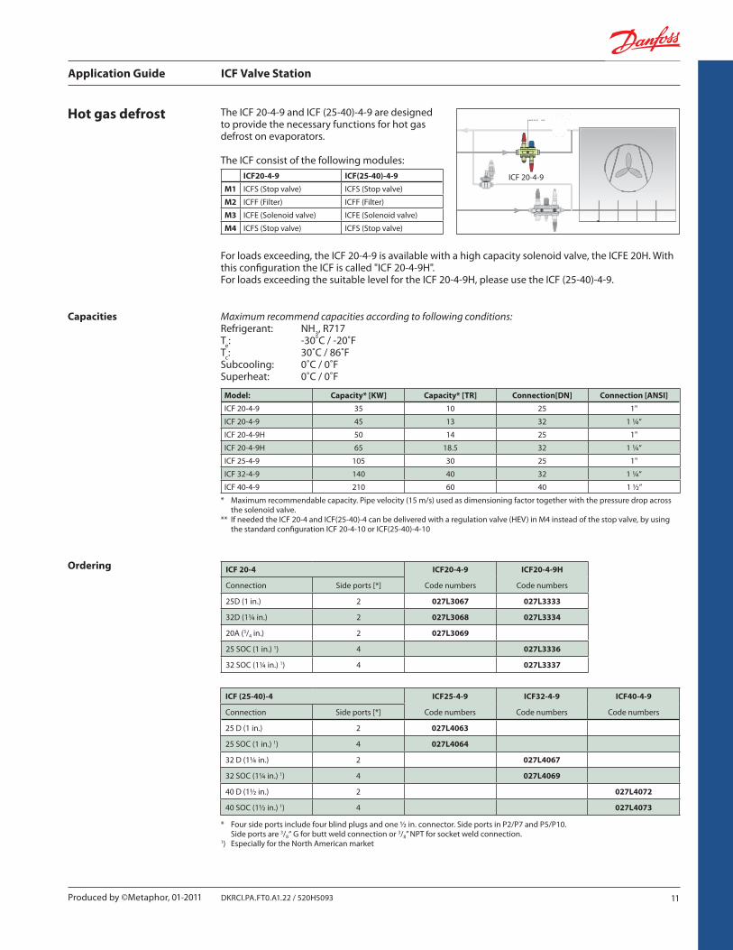
ICF 20-4-9
Hot gas defrost The ICF 20-4-9 and ICF (25-40)-4-9 are designed to provide the necessary functions for hot gas defrost on evaporators.
The ICF consist of the following modules:
For loads exceeding, the ICF 20-4-9 is available with a high capacity solenoid valve, the ICFE 20H. With this configuration the ICF is called "ICF 20-4-9H". For loads exceeding the suitable level for the ICF 20-4-9H, please use the ICF (25-40)-4-9.
Ordering ICF 20-4 ICF20-4-9 ICF20-4-9H
Connection Side ports [*] Code numbers Code numbers
25D (1 in.) 2 027L3067 027L3333
32D (1¼ in.) 2 027L3068 027L3334
20A (3/4 in.) 2 027L3069
25 SOC (1 in.) 1) 4 027L3336
32 SOC (1¼ in.) 1) 4 027L3337
ICF (25-40)-4 ICF25-4-9 ICF32-4-9 ICF40-4-9
Connection Side ports [*] Code numbers Code numbers Code numbers
25 D (1 in.) 2 027L4063
25 SOC (1 in.) 1) 4 027L4064
32 D (1¼ in.) 2 027L4067
32 SOC (1¼ in.) 1) 4 027L4069
40 D (1½ in.) 2 027L4072
40 SOC (1½ in.) 1) 4 027L4073
* Four side ports include four blind plugs and one ½ in. connector. Side ports in P2/P7 and P5/P10. Side ports are 3/8“ G for butt weld connection or 3/8” NPT for socket weld connection.1) Especially for the North American market
ICF20-4-9 ICF(25-40)-4-9
M1 ICFS (Stop valve) ICFS (Stop valve)
M2 ICFF (Filter) ICFF (Filter)
M3 ICFE (Solenoid valve) ICFE (Solenoid valve)
M4 ICFS (Stop valve) ICFS (Stop valve)
Capacities
* Maximum recommendable capacity. Pipe velocity (15 m/s) used as dimensioning factor together with the pressure drop across the solenoid valve. ** If needed the ICF 20-4 and ICF(25-40)-4 can be delivered with a regulation valve (HEV) in M4 instead of the stop valve, by using the standard configuration ICF 20-4-10 or ICF(25-40)-4-10
Maximum recommend capacities according to following conditions: Refrigerant: NH3, R717Te: -30˚C / -20˚FTc: 30˚C / 86˚FSubcooling: 0˚C / 0˚FSuperheat: 0˚C / 0˚F
Model: Capacity* [KW] Capacity* [TR] Connection[DN] Connection [ANSI]
ICF 20-4-9 35 10 25 1"
ICF 20-4-9 45 13 32 1 ¼“
ICF 20-4-9H 50 14 25 1"
ICF 20-4-9H 65 18.5 32 1 ¼“
ICF 25-4-9 105 30 25 1"
ICF 32-4-9 140 40 32 1 ¼“
ICF 40-4-9 210 60 40 1 ½”
Application Guide ICF Valve Station
12 DKRCI.PA.FT0.A1.22 / 520H5093 Produced by ©Metaphor, 01-2011
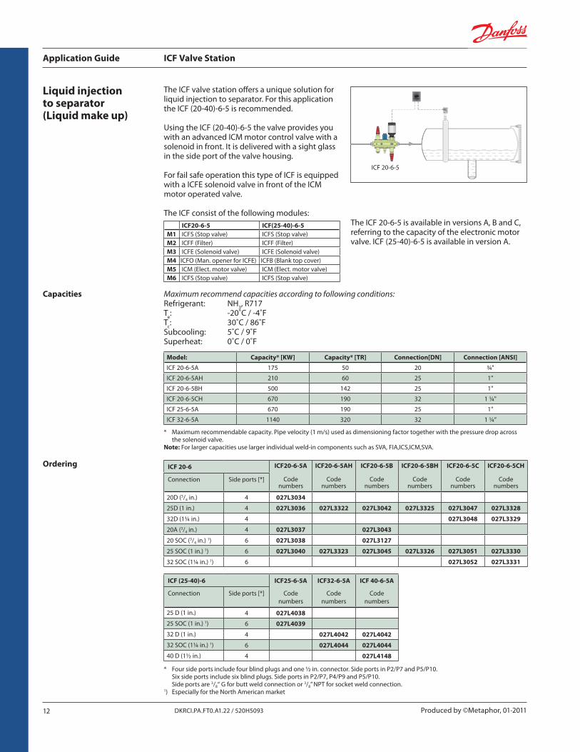
ICF 20-6-5
Liquid injection to separator (Liquid make up)
The ICF valve station offers a unique solution for liquid injection to separator. For this application the ICF (20-40)-6-5 is recommended.
Using the ICF (20-40)-6-5 the valve provides you with an advanced ICM motor control valve with a solenoid in front. It is delivered with a sight glass in the side port of the valve housing.
For fail safe operation this type of ICF is equipped with a ICFE solenoid valve in front of the ICM motor operated valve.
The ICF consist of the following modules:The ICF 20-6-5 is available in versions A, B and C, referring to the capacity of the electronic motor valve. ICF (25-40)-6-5 is available in version A.
Ordering
* Four side ports include four blind plugs and one ½ in. connector. Side ports in P2/P7 and P5/P10. Six side ports include six blind plugs. Side ports in P2/P7, P4/P9 and P5/P10. Side ports are 3/8“ G for butt weld connection or 3/8” NPT for socket weld connection.1) Especially for the North American market
ICF20-6-5 ICF(25-40)-6-5M1 ICFS (Stop valve) ICFS (Stop valve)M2 ICFF (Filter) ICFF (Filter)M3 ICFE (Solenoid valve) ICFE (Solenoid valve)M4 ICFO (Man. opener for ICFE) ICFB (Blank top cover)M5 ICM (Elect. motor valve) ICM (Elect. motor valve)M6 ICFS (Stop valve) ICFS (Stop valve)
ICF 20-6 ICF20-6-5A ICF20-6-5AH ICF20-6-5B ICF20-6-5BH ICF20-6-5C ICF20-6-5CH
Connection Side ports [*] Code numbers
Code numbers
Code numbers
Code numbers
Code numbers
Code numbers
20D (3/4 in.) 4 027L3034
25D (1 in.) 4 027L3036 027L3322 027L3042 027L3325 027L3047 027L3328
32D (1¼ in.) 4 027L3048 027L3329
20A (3/4 in.) 4 027L3037 027L3043
20 SOC (3/4 in.) 1) 6 027L3038 027L3127
25 SOC (1 in.) 1) 6 027L3040 027L3323 027L3045 027L3326 027L3051 027L3330
32 SOC (1¼ in.) 1) 6 027L3052 027L3331
ICF (25-40)-6 ICF25-6-5A ICF32-6-5A ICF 40-6-5A
Connection Side ports [*] Code numbers
Code numbers
Code numbers
25 D (1 in.) 4 027L4038
25 SOC (1 in.) 1) 6 027L4039
32 D (1 in.) 4 027L4042 027L4042
32 SOC (1¼ in.) 1) 6 027L4044 027L4044
40 D (1½ in.) 4 027L4148
Capacities
Model: Capacity* [KW] Capacity* [TR] Connection[DN] Connection [ANSI]
ICF 20-6-5A 175 50 20 ¾"
ICF 20-6-5AH 210 60 25 1"
ICF 20-6-5BH 500 142 25 1"
ICF 20-6-5CH 670 190 32 1 ¼"
ICF 25-6-5A 670 190 25 1"
ICF 32-6-5A 1140 320 32 1 ¼“
Maximum recommend capacities according to following conditions:Refrigerant: NH3, R717Te: -20˚C / -4˚FTc: 30˚C / 86˚FSubcooling: 5˚C / 9˚FSuperheat: 0˚C / 0˚F
* Maximum recommendable capacity. Pipe velocity (1 m/s) used as dimensioning factor together with the pressure drop across the solenoid valve. Note: For larger capacities use larger individual weld-in components such as SVA, FIA,ICS,ICM,SVA.
Application Guide ICF Valve Station
13DKRCI.PA.FT0.A1.22 / 520H5093Produced by ©Metaphor, 01-2011
u
v
w
xy
v Pressure transmittersAKS 33 G 3/8” (Qty. 1)
LP -1 to 12 bar (-30 to 40°C) 060G2105
AKS 33 G 3/8” (Qty. 1)
HP 0 to 25 bar (0 to 80°C) 060G2115
AKS 33 1/4" NPT (Qty. 1)
0-100 psia(-40 - 185°F)060G3802
AKS 33 1/4" NPT (Qty. 1)
0-200 psia(-40 - 185°F)060G1711
Other AKS 33 types see literature: RD5GH
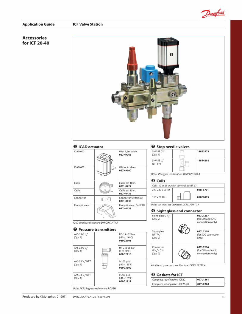
Accessories for ICF 20-40
u ICAD actuatorICAD 600 With 1,5m cable
027H9065
ICAD 600 Without cables 027H9100
Cable Cable set 10 m. 027H0427
Cable Cable set 15 m. 027H0435
Connector Connector set female027H0430
Protection cap Protection cap for ICAD027H0431
ICAD details see literature: DKRCI.PD.HT0.A
w CoilsCoils 10 W 21 VA with terminal box IP 67
220-230 V 50 Hz 018F6701
115 V 60 Hz 018F6813
Other coil types see literature: DKRCI.PD.FT0.A
v Stop needle valvesSNV-ST G½” (Qty. 1)
148B3778
SNV-ST 3/8" NPT-FPT
148B4181
Other SNV types see literature: DKRCI.PD.KB0.A
x Sight glass and connectorSight glass G 3/8” (Qty. 2)
027L1267(for DIN and ANSI connections only)
Sight glass NPT 3/8” (Qty. 2)
027L1268(for SOC connection only)
Connector G 3/8”– G½” (Qty. 2)
027L1266(for DIN and ANSI connections only)
Additional spare parts see literature: DKRCI.PY.FT0.A
y Gaskets for ICFComplete set of gaskets ICF20 027L1261
Complete set of gaskets ICF25-40 027L2260

Produced by ©Metaphor, 01-2011
Produced by ©Metaphor, 01-2011
16 DKRCI.PA.FT0.A1.22 / 520H5093 Produced by ©Metaphor, 01-2011
Danfoss Industrial RefrigerationYour “One-Stop-Shop”
For further information; please visit our web sitewww.danfoss.com/ir
ICF Control Solution ICV Control Valves Liquid Level Controls Line Components Stop and Regulating Valves Safety Relief Valves
We also offer a wide range of products for CO2.
All our products are designed and tested to ensure that they can withstand the impact of CO
2 in all aspects.
Please visit www.danfoss.com/co2
We have more than 60 years of experience producing valves and controllers for Industrial Refrigeration and we focus on our core business of making quality products that enhance performance and reduce total life cycle costs – the key to major savings.
Some of the products from our very extensive product range:
MAKING MODERN LIVING POSSIBLE