Embed Size (px)
Citation preview

51103A_p.book : 51103A_t.fm Page 1 Friday, December 19, 1997 10:35 AM
1997 Microchip Technology Inc. DS51103A
ICEPIC Emulator User’s Guide
ICEPIC was designed by NEOSOFT Inc. and is manufactured under license by RF Solutions Ltd. To order or obtain more information about ICEPIC or any other Microchip product, contact the Microchip sales office nearest you.
Information contained in this publication regarding device applications and the like is intended through suggestion only and may be superseded by updates. No representation or warranty is given and no liability is assumed by Microchip Technology Incorporated with respect to the accuracy or use of such information, or infringement of patents or other intellectual property rights arising from such use or otherwise. Use of Microchip’s products as critical components in life support systems is not authorized except with express written approval by Microchip. No licenses are conveyed, implicitly or otherwise, under any intellectual property rights.
The Microchip logo, name, PIC, PICMASTER, PICSTART and PRO MATE are registered trademarks of Microchip Technology Incorporated in the U.S.A. and other countries. PICmicro, ICEPIC, microID, Smart Serial and MPLAB are trademarks of Microchip in the U.S.A. and other countries.
© Microchip Technology Incorporated 1997.
fuzzyTECH is a registered trademark of Inform Software Corporation.
Intel is a registered trademark of Intel Corporation.
DOS and IBM PC/AT are registered trademark of International Business Machines Corporation.
MS-DOS, Windows and Excel are registered trademarks of Microsoft Corporation.
CompuServe is a registered trademark of CompuServe Incorporated.
DriveWay is a trademark of Aisys Intelligent Systems.
All rights reserved. All other trademarks mentioned herein are the property of their respective companies.

ICEPIC
51103A_p.book : 51103A_t.fm Page 2 Friday, December 19, 1997 10:35 AM
NOTES:
DS51103A 1997 Microchip Technology Inc.

ICEPIC EmulatorUser’s Guide
51103A_p.book : 51103A_pTOC.fm Page i Friday, December 19, 1997 10:35 AM
Table of Contents
Preview
MPLABTM Integrated Development Environment . . . . . . . . . . . . . . . . . . . . . . . 1
MPLAB Development Tools. . . . . . . . . . . . . . . . . . . . . . . . . . . . . . . . . . . . . . . . 1
What is the ICEPIC Emulator . . . . . . . . . . . . . . . . . . . . . . . . . . . . . . . . . . . . . . 2
How the ICEPIC Emulator Helps You . . . . . . . . . . . . . . . . . . . . . . . . . . . . . . . . 2
Chapter 1. About ICEPIC EmulatorIntroduction . . . . . . . . . . . . . . . . . . . . . . . . . . . . . . . . . . . . . . . . . . . . . . . . . . . . 3
Emulator Components . . . . . . . . . . . . . . . . . . . . . . . . . . . . . . . . . . . . . . . . . . . . 3
Emulator Architecture . . . . . . . . . . . . . . . . . . . . . . . . . . . . . . . . . . . . . . . . . . . . 4
Hardware and Software Requirements . . . . . . . . . . . . . . . . . . . . . . . . . . . . . . . 4
Recommended Reading . . . . . . . . . . . . . . . . . . . . . . . . . . . . . . . . . . . . . . . . . . 5
Warranty Registration . . . . . . . . . . . . . . . . . . . . . . . . . . . . . . . . . . . . . . . . . . . . 5
Customer Support . . . . . . . . . . . . . . . . . . . . . . . . . . . . . . . . . . . . . . . . . . . . . . . 6
Chapter 2. ICEPIC Emulator InstallationUnpacking the System. . . . . . . . . . . . . . . . . . . . . . . . . . . . . . . . . . . . . . . . . . . . 7
Installing ICEPIC Emulator Hardware . . . . . . . . . . . . . . . . . . . . . . . . . . . . . . . . 7
Installing Software . . . . . . . . . . . . . . . . . . . . . . . . . . . . . . . . . . . . . . . . . . . . . . . 8
Getting the Most From MPLAB - Using Projects . . . . . . . . . . . . . . . . . . . . . . . 10
Where to go from Here . . . . . . . . . . . . . . . . . . . . . . . . . . . . . . . . . . . . . . . . . . 10
Chapter 3. ICEPIC Emulator Basic FunctionsIntroduction . . . . . . . . . . . . . . . . . . . . . . . . . . . . . . . . . . . . . . . . . . . . . . . . . . . 11
Highlights . . . . . . . . . . . . . . . . . . . . . . . . . . . . . . . . . . . . . . . . . . . . . . . . . . . . . 11
Program Execution . . . . . . . . . . . . . . . . . . . . . . . . . . . . . . . . . . . . . . . . . . . . . 11
Real Time Execution . . . . . . . . . . . . . . . . . . . . . . . . . . . . . . . . . . . . . . . . . . . . 11
Polled Execution . . . . . . . . . . . . . . . . . . . . . . . . . . . . . . . . . . . . . . . . . . . . . . . 12
Animate Mode . . . . . . . . . . . . . . . . . . . . . . . . . . . . . . . . . . . . . . . . . . . . . . . . . 12
Breakpoints . . . . . . . . . . . . . . . . . . . . . . . . . . . . . . . . . . . . . . . . . . . . . . . . . . . 12
Real Time Breakpoints . . . . . . . . . . . . . . . . . . . . . . . . . . . . . . . . . . . . . . . . . . 13
Hardware Dialog . . . . . . . . . . . . . . . . . . . . . . . . . . . . . . . . . . . . . . . . . . . . . . . 14
Conditional Break Dialog . . . . . . . . . . . . . . . . . . . . . . . . . . . . . . . . . . . . . . . . . 14
Program Memory in the ICEPIC Emulator . . . . . . . . . . . . . . . . . . . . . . . . . . . . 16
1997 Microchip Technology Inc. DS51103A - page i

ICEPIC
51103A_p.book : 51103A_pTOC.fm Page ii Friday, December 19, 1997 10:35 AM
Chapter 4. ICEPIC Emulator Menu OptionsIntroduction . . . . . . . . . . . . . . . . . . . . . . . . . . . . . . . . . . . . . . . . . . . . . . . . . . . 17
Highlights . . . . . . . . . . . . . . . . . . . . . . . . . . . . . . . . . . . . . . . . . . . . . . . . . . . . . 17
File Menu . . . . . . . . . . . . . . . . . . . . . . . . . . . . . . . . . . . . . . . . . . . . . . . . . . . . . 17
Debug Menu . . . . . . . . . . . . . . . . . . . . . . . . . . . . . . . . . . . . . . . . . . . . . . . . . . 17
Options Menu . . . . . . . . . . . . . . . . . . . . . . . . . . . . . . . . . . . . . . . . . . . . . . . . . 18
Tools Menu . . . . . . . . . . . . . . . . . . . . . . . . . . . . . . . . . . . . . . . . . . . . . . . . . . . 20
Configure Probe. . . . . . . . . . . . . . . . . . . . . . . . . . . . . . . . . . . . . . . . . . . . . . . . 20
Chapter 5. Trouble Shooting GuideIntroduction . . . . . . . . . . . . . . . . . . . . . . . . . . . . . . . . . . . . . . . . . . . . . . . . . . . 21
Highlights . . . . . . . . . . . . . . . . . . . . . . . . . . . . . . . . . . . . . . . . . . . . . . . . . . . . . 21
Hardware Related Problems . . . . . . . . . . . . . . . . . . . . . . . . . . . . . . . . . . . . . . 21
Software Related Problems. . . . . . . . . . . . . . . . . . . . . . . . . . . . . . . . . . . . . . . 22
Appendix A. On-Line SupportIntroduction . . . . . . . . . . . . . . . . . . . . . . . . . . . . . . . . . . . . . . . . . . . . . . . . . . . 23
Connecting to the Microchip Internet Web Site . . . . . . . . . . . . . . . . . . . . . . . . 23
Connecting to the Microchip BBS . . . . . . . . . . . . . . . . . . . . . . . . . . . . . . . . . . 24
Using the Bulletin Board . . . . . . . . . . . . . . . . . . . . . . . . . . . . . . . . . . . . . . . . . 24
Software Releases. . . . . . . . . . . . . . . . . . . . . . . . . . . . . . . . . . . . . . . . . . . . . . 25
Systems Information and Upgrade Hot Line . . . . . . . . . . . . . . . . . . . . . . . . . . 26
Appendix B. SpecificationsSerial Port Specification. . . . . . . . . . . . . . . . . . . . . . . . . . . . . . . . . . . . . . . . . . 27
Appendix C. Emulator LimitationsProcessor Specific Limitations. . . . . . . . . . . . . . . . . . . . . . . . . . . . . . . . . . . . . 29
ICEPIC System Specific Limitations . . . . . . . . . . . . . . . . . . . . . . . . . . . . . . . . 29
Appendix D. Diagnostic ProgramDiagnostic Program . . . . . . . . . . . . . . . . . . . . . . . . . . . . . . . . . . . . . . . . . . . . . 31
Appendix E. Daughter Board LinksDaughter Board Links . . . . . . . . . . . . . . . . . . . . . . . . . . . . . . . . . . . . . . . . . . . 35
IndexIndex . . . . . . . . . . . . . . . . . . . . . . . . . . . . . . . . . . . . . . . . . . . . . . . . . . . . . . . . 37
DS51103A - page ii 1997 Microchip Technology Inc.

ICEPIC
51103A_p.book : 51103A_p.fm Page 1 Friday, December 19, 1997 10:35 AM
ICEPIC Emulator Preview
MPLABTM Integrated Development EnvironmentThe MPLAB desktop provides development tools and an environment for developing and debugging your applications as a project.
This document covers the basic set up and operation of the ICEPIC emulator, but it does not cover all functions of the MPLAB Integrated Development Environment (IDE). Read the MPLAB User’s Guide to get a full understanding of the features and debug capabilities of the MPLAB Integrated Development Environment.
MPLAB Development ToolsThe MPLAB Integrated Development Environment allows you to quickly move between different development/debugging modes. For example, you can quickly advance from debugging with the simulator to debugging with the ICEPIC emulator.
The MPLAB Integrated Development Environment includes the following development tools:
MPLAB Project ManagerThe Project Manager enables you to create a project, and work with specific files related to the project. The MPLAB Project Manager also allows you to build an application and download your code to the emulator or the simulator with a mouse click.
MPLAB EditorThe MPLAB Editor allows you to write and edit firmware source files or other text files for PlCmicroTM MCUs.
MPLAB-SIM SimulatorThe simulator models instruction execution of PICmicro MCUs and PICmicro I/O at the speed of your CPU.
PICMASTER® EmulatorThe PICMASTER emulator uses hardware to emulate PICmicro MCUs in real time. This is Microchip’s universal emulator and supports all PICmicros.
PICSTART® Plus Device ProgrammerA highly flexible low-cost programmer for all PICmicro 8-bit OTP devices (DIP packages).
1997 Microchip Technology Inc. DS51103A - page 1

ICEPIC
51103A_p.book : 51103A_p.fm Page 2 Friday, December 19, 1997 10:35 AM
PRO MATE® Device ProgrammerA universal robust programmer for all PICmicro, KEELOQ® and many Microchip memory devices.
ICEPIC EmulatorThe ICEPIC emulator uses hardware to emulate most 12-bit and 14-bit PICmicro MCUs in real time.
Universal PICmicro MCU AssemblerThe MPASM Universal PICmicro MCU Assembler allows you to assemble your code without exiting MPLAB.
What is the ICEPIC EmulatorThe ICEPIC Emulator is a hardware debugging tool that operates with the MPLAB Integrated Development Environment. MPLAB has software tools to debug source code and MPLAB-SIM to simulate PICmicro MCU instructions and simple I/O. The ICEPIC emulator is one of the MPLAB tools. MPLAB with the ICEPIC emulator can debug application hardware as it executes in real-time.
An emulator, also called an in-circuit emulator or ICE, differs from a simulator in these areas:
I/O – The emulator has I/O and on-chip devices that function exactly like the target processor. In comparison, a simulator provides limited I/O and is a limited model of the special functions of a microcontroller.
Execution Speed – The emulator runs code and responds to external and internal events at the same speed the application runs.
The ICEPIC emulator connects into application hardware and runs like the PIC16C5X/16CXX microcontroller in your design. The emulator probe plugs into the PIC16C5X/16CXX socket on your application, and runs your code from ICEPIC emulation memory.
How the ICEPIC Emulator Helps YouThe ICEPIC emulator allows you to:
• Debug your source code on your own hardware.
• Debug your firmware in real time.
• Debug with hardware breakpoints.
• Watch/Modify internal registers and status of the processor.
DS51103A - page 2 1997 Microchip Technology Inc.
ICEPIC
51103A_p.book : 51103A_1.fm Page 3 Friday, December 19, 1997 10:35 AM
Chapter 1. About ICEPIC Emulator
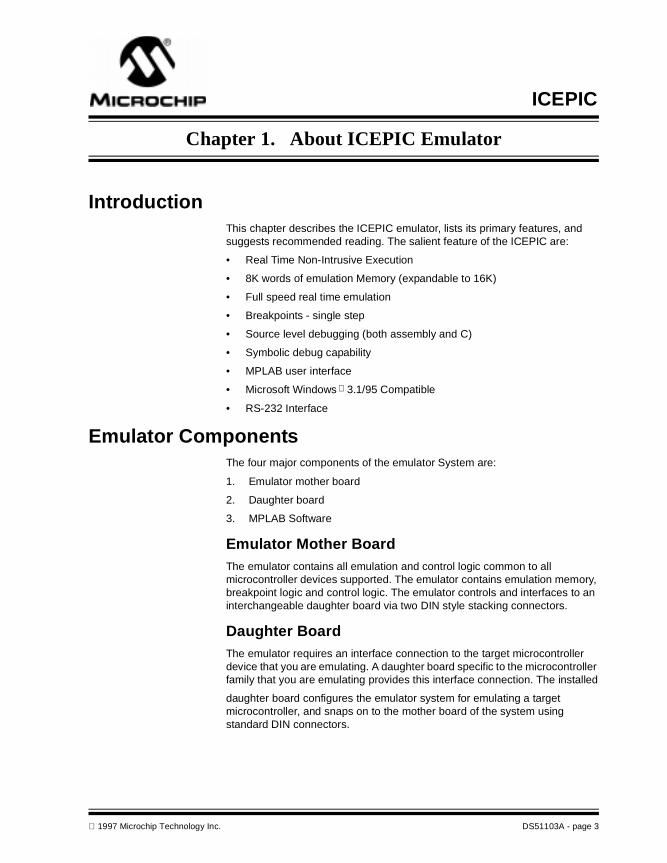
IntroductionThis chapter describes the ICEPIC emulator, lists its primary features, and suggests recommended reading. The salient feature of the ICEPIC are:
• Real Time Non-Intrusive Execution
• 8K words of emulation Memory (expandable to 16K)
• Full speed real time emulation
• Breakpoints - single step
• Source level debugging (both assembly and C)
• Symbolic debug capability
• MPLAB user interface
• Microsoft Windows 3.1/95 Compatible
• RS-232 Interface
Emulator ComponentsThe four major components of the emulator System are:
1. Emulator mother board
2. Daughter board
3. MPLAB Software
Emulator Mother BoardThe emulator contains all emulation and control logic common to all microcontroller devices supported. The emulator contains emulation memory, breakpoint logic and control logic. The emulator controls and interfaces to an interchangeable daughter board via two DIN style stacking connectors.
Daughter BoardThe emulator requires an interface connection to the target microcontroller device that you are emulating. A daughter board specific to the microcontroller family that you are emulating provides this interface connection. The installed
daughter board configures the emulator system for emulating a target microcontroller, and snaps on to the mother board of the system using standard DIN connectors.
1997 Microchip Technology Inc. DS51103A - page 3

ICEPIC
51103A_p.book : 51103A_1.fm Page 4 Friday, December 19, 1997 10:35 AM
Interchangeable daughter boards allow development engineers to easily reconfigure the emulator system for emulating different target processors. The daughter boards operating frequencies may range up to 20 MHz, depending on the daughter board.
Supporting ICEPIC daughter boards for future microcontroller devices will be made available as Microchip releases future devices.
MPLAB SoftwareThe MPLAB software runs in the Windows 3.1 or greater environment, and provides full display, modification, and control of the target application under emulation. MPLAB software supports the PICmicro MCU families. The MPLAB software automatically identifies the probe type, and configures the emulator system for emulating the target processor.
With MPLAB and MS Windows you can concurrently run many programs such as inter-office mail, spreadsheets, and ICEPIC.
Emulator ArchitectureThe universal architecture of the emulator allows expansion to support all new PIC16C5X and PIC16CXX microcontrollers. Data and program memory paths extend to 14 bits.
Hardware and Software RequirementsThe emulator system is designed to operate on most PC compatible 386 or better class systems running MS Windows 3.1 or Windows 95, This real-time emulation system provides advanced features generally found on more expensive development tools.
Host Computer System RequirementsTo take advantage of the emulator system features, you must install the MPLAB software (MPLAB.EXE) on a host computer having the following minimum configuration:
• PC compatible machine: 386 or higher.
• VGA required. SuperVGA recommended.
• MS-DOS /PC-DOS version 5.0 or greater.
• Microsoft Windows version 3.1 or greater operating in 386 enhanced mode.
• 4 MB of Memory, 16 MB Recommended8 MB of Hard Disk Space, 20 MB Recommended
• One free serial port.A serial port with PIC16C550 is recommended for speeds greater than 19.2K.
• Mouse or other pointing device
DS51103A - page 4 1997 Microchip Technology Inc.
Chapter 1. About ICEPIC Emulator
51103A_p.book : 51103A_1.fm Page 5 Friday, December 19, 1997 10:35 AM
Recommended ReadingREADME.IP Is an ASCII text file on the ICEPIC diskette. This file contains update information that may not be included in the ICEPIC User’s Guide.
LINKS.TXT For the jumper links settings on the daughter boards
README.XXX For the latest information on using other tools, an information file about the product may exist that is more current than the printed manual. Check the MPLAB directory for other README files. (In the case of MPASM, for instance, the file is called README.ASM.)
PICmicro Microcontroller Data Book Contains comprehensive data sheets for Microchip PICmicro MCU devices available at print time. Document Number DS00158, Microchip Technology Inc., Chandler, AZ.
Embedded Control Handbook Contains a wealth of information about microcontroller applications. Document Number DS00092, Microchip Technology Inc., Chandler, AZ. The application notes described in this manual are also available from the Microchip BBS and the Microchip Internet Home Page. See Appendix B for more information.
Microchip ECHB Update I Contains additional application notes released since publication of the standard Embedded Control Handbook.
MPASM with MPLINK and MPLIB User’s Guide Describes how to use Microchip Universal PICmicro MCU Assembler (MPASM). Document Number DS33014, Microchip Technology, Chandler, AZ.
ICEPIC Pod Electrical Specifications Contains ICEPIC Pod electrical specifications, Microchip Technology, Chandler, AZ.
All of the above documents are available from your local sales office or your Microchip Field Application Engineer (FAE).
This manual assumes that you are familiar with both MS-DOS and Microsoft Windows 3.x software systems. Many excellent references exist for both of these software programs, and should be consulted for general operation of DOS™ and Windows.
Warranty RegistrationSending in your Warranty Registration Card ensures that you receive new product updates and notification of interim software releases that may become available.
1997 Microchip Technology Inc. DS51103A - page 5

ICEPIC
51103A_p.book : 51103A_1.fm Page 6 Friday, December 19, 1997 10:35 AM
Customer SupportMicrochip endeavors to provide the best service and responsiveness possible to its customers. Technical support questions should first be directed to your distributor and representative, local sales office, Field Application Engineer (FAE), or Corporate Applications Engineer (CAE).
The Microchip Internet Home Page can provide you with technical information, application notes, and promotional news on Microchip products and technology. The Microchip Web address is http://www.microchip.com.
You can also check with the Microchip BBS (Bulletin Board System) for non-urgent support, customer forums, and the latest revisions of Microchip systems development products. Refer to the "On Line Support" Appendix for access information.
DS51103A - page 6 1997 Microchip Technology Inc.

ICEPIC
51103A_p.book : 51103A_2.fm Page 7 Friday, December 19, 1997 10:35 AM
Chapter 2. ICEPIC Emulator Installation
Unpacking the System
Packing ListThe ICEPIC emulator system includes several items:
• An emulator system and a DB-9 RS-232 cable to connect it to the COM port
• A power supply
• Disks with complete system software and documentation
• A warranty registration card
• Manuals - ICEPIC Emulator User's Guide (this document), MPLAB User's Guide, and MPASM with MPLINK and MPLIB User's Guide.
Installing ICEPIC Emulator HardwareThe following steps should be followed to install your ICEPIC Emulator hardware. If you already have installed the ICEPIC Emulator system then skip to the next section, "Installing Software".
Hardware InstallationListed below is the procedure for the correct power-up sequence,
1. Ensure the target cables are properly connected and the OscillatorModule is connected. Note the OSC module is inserted with the correctorientation!
2. Connect the ribbon cable header into the target application. Note: Pin 1of the ribbon cable is colored "red", Pin 1 of the DIP header connector isadjacent to the "red" side of the cable.
3. Connect the ICEPIC-In circuit emulator power supply.
4. Connect the RS-232 cable between host computer and the rear panelof the ICEPIC-In circuit emulator pod.
5. Turn on the power to the host computer
6. Turn on the power to the ICEPIC in-circuit emulator pod.
7. Turn on the power to the target application.
8. It is recommended that the MCLR pin on the target board is not held low.
Removal of Daughter Board;1. Ensure all power is disconnected,
2. Disconnect the RS-232 cable to the host computer and header cable tothe target application.
1997 Microchip Technology Inc. DS51103A - page 7

ICEPIC
51103A_p.book : 51103A_2.fm Page 8 Friday, December 19, 1997 10:35 AM
3. Place the ICEPIC in-circuit emulator pod upside-down. Unscrew thetwo screws to release the bottom half of the plastic case assembly andfront panel.
4. Turn the pod upright. Carefully ease off the daughter board (the topPCB) from the two "DIN41612" type connectors.
Installation of Daughter Board;1. Complete the removal of the existing daughter board.
2. Installation of a daughter board is a simple push fit onto the main board,connecting only by the two "DIN41612" type connectors. Ensure thecorrect polarity of the daughter board.
3. Ensure the emulator crystal (XTAL) and target header cable aresecurely inserted.
4. Slide in the front panel into the case slots.
5. Replace the bottom half of the plastic case assembly, ensure the targetcable(s) pass through the slot in the front panel. Insert the two casescrews.
Configuration of Daughter Board;There are several jumper links which are used to configure your daughter board. These are all preset during manufacture. Please refer to "Links.Txt" for more information on jumper link settings.
Applying Power to System ComponentsConnect the power supply (included with the system) to the system and turn On the power switch. The power LED on the front panel must now be on. Power up the system components in the following sequence to prevent damage to any of the sub-system parts or user target application parts:
1. Apply power to the emulator assembly.
2. Apply power to the target board.
The emulator hardware and target application are now ready for emulation.
Power Down System Components
1. Remove power from user target system
2. Remove power from emulator system.
Installing SoftwareThe ICEPIC software is an add on tool for MPLAB software. Therefore, to install ICEPIC software, MPLAB must be already installed on your system. If not, please install MPLAB and then install ICEPIC.
Note: Do not exceed the voltage specifications for the emulator pod or any probe device as described in the respective data sheets.
Tip: Before replacing the plastic box, you may wish to configure Jumper Link3(MCLR).
DS51103A - page 8 1997 Microchip Technology Inc.

Chapter 2. ICEPIC Emulator Installation
51103A_p.book : 51103A_2.fm Page 9 Friday, December 19, 1997 10:35 AM
To install ICEPIC, follow these steps:
1. Enter Microsoft Windows and insert the MPLAB-ICEPIC installationdisk 1 into drive A.
2. From the File Manager, or the Program Manager > Run option, runa:setup.
3. Follow the on-line instructions.
Communicating with the ICEPIC HardwareUse the following steps to set up the MPLAB software for use with the ICEPIC hardware. Once proper operation is established, no further changes are needed unless reconfiguration is desired.
1. Make sure the emulator is connected to the PC with the serial cable.Make sure there is a probe connected to the emulator and turn onemulator power.
2. From the Microchip MPLAB program group, run MPLAB.
3. MPLAB will either find the emulator and start, or it will display amessage that it cannot find the emulator. If it finds the emulator youmay skip to Appendix A: On-Line Support. If the emulator is not found,continue with step 4.
4. Select the Editor Only option from the dialog. MPLAB will start withoutattempting to connect to the emulator.
5. Select the Options > Development Mode menu item to open theDevelopment Mode dialog.
6. Select ICEPIC Emulator.
7. Select desired com port and baud rate for communicating with ICEPIC.
8. Click "Reset" button.
Figure 2.1 Development Mode Dialog Box
1997 Microchip Technology Inc. DS51103A - page 9

ICEPIC
51103A_p.book : 51103A_2.fm Page 10 Friday, December 19, 1997 10:35 AM
Getting the Most From MPLAB - Using ProjectsMPLAB is the host software for the ICEPIC emulator and the MPLAB-SIM simulator. It functions as a sophisticated debugging tool, providing access to RAM, ROM, EEPROM, and a variety of other debug functions. To realize the true capabilities of MPLAB, you must use it as a project manager as well.
Perform the following steps to gain some familiarity with the MPLAB projects:
1. Select Project > New Project to create a new project. The projectmanager will create a project file of the same name as the file youchoose, except it will have the extension *.PJT.
2. Add a file to the project. When you close the New Project dialog the EditProject dialog opens automatically. Add the files you want to this projectand close the dialog. Since the linker is not currently available, MPLABonly supports one source file per project. However, that file can includeother files.
3. Select Project > Build All. MPLAB rebuilds all of the files in the project. Ifyou select Project > Make Project, MPLAB only rebuilds the files thathave changed. If there are any errors in the source code, MPLABdisplays the error file and allows you to go immediately to the file andline where the error occurred by double-clicking on the error line.
4. Open the Source code using File > Open Source. Select the Window >Program Memory, Window > File Registers, and Window > SpecialFunction Registers to open the corresponding windows.
5. Select Project > Close Project. MPLAB records the open windows andtheir positions when you select Yes from the close project message box.
6. Select Project > Open Project. MPLAB reopens all of the projectwindows, reloads the binary code into the emulator, and loads thesymbol information for debugging.
7. Using Run, Halt, Step, and Reset from the toolbar or the Debug > Runmenu, you can debug your application from your source code. If youdiscover a bug in your source code, you can correct it immediately,recompile and reload the code into the emulator with a single keystroke(Project > Make Project or F10).
Where to go from HereFor all users, we recommend you work through the tutorial on projects in the MPLAB User’s Guide. This tutorial gives you an overview of the debugging capabilities of the MPLAB system.
Note: If you do not put your source files into a project, MPLAB cannot debug properly.
DS51103A - page 10 1997 Microchip Technology Inc.

ICEPIC
51103A_p.book : 51103A_3.fm Page 11 Friday, December 19, 1997 10:35 AM
Chapter 3. ICEPIC Emulator Basic Functions
IntroductionThis chapter briefly discusses the basic MPLAB debugging functions of the ICEPIC emulator. For more information on general debugging features, refer to the MPLAB User’s Guide.
HighlightsThis chapter covers the following information:
• Program Execution
• Breakpoints
• Hardware Dialog
• Conditional Break Dialog
• Program Memory in the ICEPIC Emulator
Program ExecutionThe emulator executes in real-time mode or in polled mode.
• Real time execution occurs when you run the processor without interruptions until encountering a valid breakpoint, or until encountering a user halt.
• Polled execution occurs when you single step the processor, modify values at a breakpoint, execute an opcode from the Debug > Execute > Execute an Opcode dialog, or use the Debug > Execute > Conditional Break dialog.
Real Time ExecutionWhen you run the emulator in real time, instructions execute just as the processor would without emulation. The emulator executes in real time until a valid breakpoint halts the emulator or until you force the emulator to halt.
To execute the emulator in real time, click the Run icon on the Tool Bar, or double click on an instruction in the Program Memory window.
Note: Double clicking on an instruction in the Program Memory window runs the emulator until the program counter reaches that same instruction again, or until the program hits a valid breakpoint.
1997 Microchip Technology Inc. DS51103A - page 11

ICEPIC
51103A_p.book : 51103A_3.fm Page 12 Friday, December 19, 1997 10:35 AM
When running in real time:
• The emulator behaves exactly as the normal chip would behave in real time.
• If break logic is enabled the emulator or simulator will halt upon encountering a valid breakpoint.
The Debug Tool Bar provides Run, Halt, and Step buttons for controlling the emulator or simulator.
Polled Execution• Polled execution occurs when you single step the processor, modify
values at a breakpoint, execute an opcode from the Debug > Execute > Execute an Opcode dialog, or use the Debug > Execute > Conditional Break dialog.
• Polled execution provides the capability to:
– Step through code, one instruction at a time, watch the programflow, and see all register contents.
– Break on a register value or condition.– Force the emulator or simulator to execute any single opcode.
The MPLAB Debug > Execute menu options allow you to control the polled execution of your firmware in the target processor.
Animate ModeAnimate Mode is a method of automatically single-stepping the processor. To view the changing registers in the Special Function Register window or the Watch windows, use Animate mode. Animate mode runs slower than the Run function, but allows you to view changing register values.
BreakpointsICEPIC allows the user to define events based upon the following elements:
BreakpointsThe breakpoints are hardware breakpoints and can be set at any program memory address location.
MPLAB limits the number of named events to a maximum of 16 in each dialog.
The following figures show the dialog boxes for assigning names to events.
DS51103A - page 12 1997 Microchip Technology Inc.

Chapter 3. ICEPIC Emulator Basic Functions
51103A_p.book : 51103A_3.fm Page 13 Friday, December 19, 1997 10:35 AM
Figure 3.1 Break Settings Dialog Box
Events in Program Memory WindowMPLAB displays the break addresses as shown in below
Figure 3.2 Program Memory Window
Real Time BreakpointsA breakpoint is a condition in which the processor executes code and halts after a certain condition is met.
The ICEPIC emulator provides the following ways to set a breakpoint:
• Break on Address Match
• Break on Stack Overflow (applies to PlC16CXX only)
1997 Microchip Technology Inc. DS51103A - page 13

ICEPIC
51103A_p.book : 51103A_3.fm Page 14 Friday, December 19, 1997 10:35 AM
• Break on Watch Dog Timer Time Out (applies to PIC16CXX only)
• Break on User Halt
Break on Address MatchBreak on Address Match allows you to halt the processor at a desired program memory address when the processor program counter equals a certain value. The processor breaks only after the valid instruction is executed. For example, if a breakpoint is set at address 5Ah, then the processor breaks after executing the instruction at address 5Ah.
Break on Stack OverflowBreak on Stack Overflow causes the ICEPIC emulator to execute a break when the stack overflows.
Break on Watch Dog TimerIf enabled, the ICEPIC emulator executes a break when a Watch Dog Timer time-out generates a device reset. The ICEPIC emulator only supports this feature on the PIC16CXX family.
Break on User HaltMPLAB executes until you press the Halt button on the Conditional Break display (Debug > Execute > Conditional Break).
Hardware DialogThe MPLAB menu selection, Options > Processor Setup > Hardware provides dialogs for setting up the ICEPIC emulator.
Conditional Break DialogThe ICEPIC emulator halts at a breakpoint when the value of a specified internal register reaches a preset value or condition.
Note: On multicycle instructions, the ICEPIC emulator ignores extra (non-instruction) fetches and breaks only on a valid instruction
Note: The ICEPIC emulator only supports Break on Stack Overflow for the PIC16CXX family. It also supports break on stack underflow for the PIC16CXX family.
DS51103A - page 14 1997 Microchip Technology Inc.
Chapter 3. ICEPIC Emulator Basic Functions
51103A_p.book : 51103A_3.fm Page 15 Friday, December 19, 1997 10:35 AM
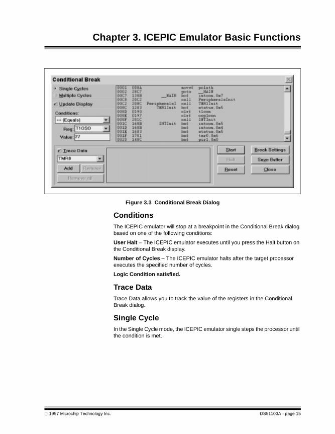
Figure 3.3 Conditional Break Dialog
ConditionsThe ICEPIC emulator will stop at a breakpoint in the Conditional Break dialog based on one of the following conditions:
User Halt – The ICEPIC emulator executes until you press the Halt button on the Conditional Break display.
Number of Cycles – The ICEPIC emulator halts after the target processor executes the specified number of cycles.
Logic Condition satisfied.
Trace DataTrace Data allows you to track the value of the registers in the Conditional Break dialog.
Single CycleIn the Single Cycle mode, the ICEPIC emulator single steps the processor until the condition is met.
1997 Microchip Technology Inc. DS51103A - page 15

ICEPIC
51103A_p.book : 51103A_3.fm Page 16 Friday, December 19, 1997 10:35 AM
Program Memory in the ICEPIC EmulatorThe ICEPIC emulator emulates program memory as described below.
PIC16C5X and PIC16CXX SeriesThe PlC16C5X and PIC16CXX series have no external memory capability. (All the program memory resides on the chip.) For these families, during development with the ICEPIC emulator, all program code resides in emulation program memory.
DS51103A - page 16 1997 Microchip Technology Inc.
ICEPIC
51103A_p.book : 51103A_4.fm Page 17 Friday, December 19, 1997 10:35 AM
Chapter 4. ICEPIC Emulator Menu Options
IntroductionThis chapter gives detailed information on using the MPLAB menu options directly applicable to the ICEPIC emulator.
HighlightsThis chapter discusses portions of the following MPLAB pull-down menus:
• File Menu
• Debug Menu
• Options Menu
• Tools Menu
File Menu
Download to Target MemoryThis command is NOT applicable to ICEPIC system.
Copy from Target MemoryThis command is NOT applicable to ICEPIC system.
Debug Menu
Run
Animate Mode
Animate Mode is a method of automatically single-stepping the processor. The simulator actually executes single steps while in run mode, but it only updates the values of the registers when it is halted. To view the changing registers in the Special Function Register window or the Watch windows, use Animate mode. Animate mode runs slower than the Run function, but allows you to view changing register values.
Update All Registers
Select Run > Update All Registers to update the displayed values for all registers to the current state of the registers – or to the condition in which the executing program left the registers.
1997 Microchip Technology Inc. DS51103A - page 17
ICEPIC
51103A_p.book : 51103A_4.fm Page 18 Friday, December 19, 1997 10:35 AM
A typical use for this command would be to check an external stimulus on the target board without executing an instruction. For example, if you change a value on an input port on the target board, you could use Update All Registers to verify the new input value.
Break SettingsSelect Debug > Break Settings to display the Breakpoint Settings dialog box for defining up to 16 named breakpoint ranges.
After entering a breakpoint title, start address, and end address, click 4 or press Enter to accept the breakpoint range definition.
System Reset (Ctrl+Shift+F3)Select Debug > System Reset to reset the entire emulator system including the hardware, software and the target processor. System Reset performs the same initialization that is performed when MPLAB is first entered.
Options Menu
Development ModeSelect Options > Development Mode to change the current Development Mode setting. Select ICEPIC emulator mode & set the COM port and the desired baud rate.
Click on the desired COM port for ICEPIC.
If MPLAB does not find the ICEPIC system, an error is reported. If this occurs, select the correct COM port and press the "Reset" button.
Select the desired baud rate.
No hardware jumpers or switch modifications are necessary. The system is auto baud capable. In most cases a baud rate of 38.4K is reliable. If serial I/O errors are reported, try reducing the baud rate to 19.2K.
Processor SetupThe Processor Setup commands allow you to configure the emulator environment.
Note: To perform a processor reset (MCLR), select Debug > Run > Reset.
Note: Always power down the emulator pod when changing probes, and then run a system reset. If you do not run a system reset after changing probes, MPLAB will not be properly configured for the new probe.
DS51103A - page 18 1997 Microchip Technology Inc.
Chapter 4. ICEPIC Emulator Menu Options
51103A_p.book : 51103A_4.fm Page 19 Friday, December 19, 1997 10:35 AM
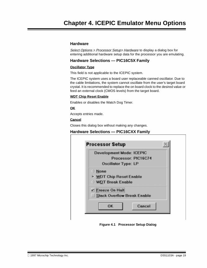
Hardware
Select Options > Processor Setup> Hardware to display a dialog box for entering additional hardware setup data for the processor you are emulating.
Hardware Selections — PIC16C5X Family
Oscillator Type
This field is not applicable to the ICEPIC system.
The ICEPIC system uses a board user replaceable canned oscillator. Due to the cable limitations, the system cannot oscillate from the user’s target board crystal. It is recommended to replace the on board clock to the desired value or feed an external clock (CMOS levels) from the target board.
WDT Chip Reset Enable
Enables or disables the Watch Dog Timer.
OK
Accepts entries made.
Cancel
Closes this dialog box without making any changes.
Hardware Selections — PIC16CXX Family
Figure 4.1 Processor Setup Dialog
1997 Microchip Technology Inc. DS51103A - page 19
ICEPIC
51103A_p.book : 51103A_4.fm Page 20 Friday, December 19, 1997 10:35 AM
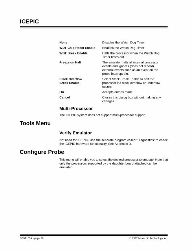
None Disables the Watch Dog Timer
WDT Chip Reset Enable Enables the Watch Dog Timer
WDT Break Enable Halts the processor when the Watch Dog Timer times out.
Freeze on Halt The emulator halts all internal processor events and ignores (does not record) external events such as an event on the probe interrupt pin.
Stack Overflow Select Stack Break Enable to halt theBreak Enable processor if a stack overflow or underflow
occurs.
OK Accepts entries made
Cancel Closes this dialog box without making any changes.
Multi-ProcessorThe ICEPIC system does not support multi-processor support.
Tools Menu
Verify Emulator
Not used for ICEPIC. Use the separate program called "Diagnostics" to check the ICEPIC hardware functionality. See Appendix D.
Configure ProbeThis menu will enable you to select the desired processor to emulate. Note that only the processors supported by the daughter board attached can be emulated.
DS51103A - page 20 1997 Microchip Technology Inc.

ICEPIC
51103A_p.book : 51103A_5.fm Page 21 Friday, December 19, 1997 10:35 AM
Chapter 5. Trouble Shooting Guide
IntroductionThe troubleshooting information in this appendix can help you with typical problems you may have in using the emulator, and describes how to resolve these problems.
HighlightsThe troubleshooting information in this chapter includes the following:
• Hardware Related Problems
• Software Related Problems
Hardware Related Problems
RS-232 Port ConnectionThe ICEPIC system communicates with the host via standard RS232 port. This requires that you have at least one free serial port on your system. The desired COM port must be supported by Windows.
If the MPLAB is unable to detect ICEPIC system on the selected COM port, try another COM port, especially if the COM ports are COM3 or COM4. Try switching to COM1 or COM2.
If occasional serial communication errors are reported, reduce the baud rate and perform a system reset.
Emulator Clock/Target System ClockEnsure you have a clock present at all times. If a clock is not present, configure the target system clock via a jumper on the probe to select the internal emulator clock or the user target system clock.
Internal Clock:
Jumper INTCLK if the emulator is to provide the system clock from the on board canned oscillator.
External Clock:
Jumper EXTCLK if the clock on the target application is to provide the system clock. Note that CMOS clock levels are required and a crystal CANNOT be used.
1997 Microchip Technology Inc. DS51103A - page 21
ICEPIC
51103A_p.book : 51103A_5.fm Page 22 Friday, December 19, 1997 10:35 AM
Software Related Problems
Breakpoints Points Disappear on DownloadIf breakpoints disappear when you download a file, the global switch, "Clear Memory on Download" may be selected in the Options > Environment Setup dialog box.
With the "Clear Memory on Download" option selected, the MPLAB software will clear emulation memory before downloading a file.
Enabling Breakpoints
Double click the breakpoints toggle in the status bar to turn breakpoints on and off.
Stack Overflow, Underflow
Stack overflow or underflow may occur for some PICmicro emulated devices. The following paragraphs detail the ICEPIC emulator hardware stack levels by family.
2-Levels Deep Hardware Stack (PIC16C5X)
Some data may be left in the stack as the PIC16C5X device has no way to clear the stack. No overflow or underflow is supported for the PIC16C5X.
8-Levels Deep Hardware Stack (PIC16CXX)
The Host Software displays an underflow or overflow message when you set Stack Break Enable on the Hardware configuration display and push or pop the stack beyond its limit. Select Options > Processor Setup > Hardware to display the Hardware configuration dialog box.
Resetting the Emulator System
Often, resetting the Emulator will clear an existing problem and allow you to continue using the ICEPIC emulator without further troubleshooting.
Select Debug > System Reset to reset the entire Emulator system (including the Hardware, Software and the target processor). System Reset performs the same initialization that is performed when the ICEPIC emulator is first loaded.
DS51103A - page 22 1997 Microchip Technology Inc.

ICEPIC
51103A_p.book : 51103A_A.fm Page 23 Friday, December 19, 1997 10:35 AM
Appendix A. On-Line Support
IntroductionMicrochip provides two methods of on-line support. These are the Microchip BBS and the Microchip World Wide Web (WWW) site.
Use Microchip’s Bulletin Board Service (BBS) to get current information and help about Microchip products. Microchip provides the BBS communication channel for you to use in extending your technical staff with microcontroller and memory experts.
To provide you with the most responsive service possible, the Microchip systems team monitors the BBS, posts the latest component data and software tool updates, provides technical help and embedded systems insights, and discusses how Microchip products provide project solutions.
The web site, like the BBS, is used by Microchip as a means to make files and information easily available to customers. To view the site, the user must have access to the Internet and a web browser, such as Netscape or Microsoft Explorer. Files are also available for FTP download from our FTP site.
Connecting to the Microchip Internet Web SiteThe Microchip web site is available by pointing your favorite Internet browser to:
www.microchip.com
The file transfer site is available by using an FTP service to connect to:
ftp://ftp.futureone.com/pub/microchip
The web site and file transfer site provide a variety of services. Users may download files for the latest Development Tools, Datasheets, Application Notes, User’s Guides, Articles and Sample Programs.
A variety of Microchip specific business information is also available, including listings of Microchip sales offices, distributors and factory representatives. Other data available for consideration is:
• Latest Microchip Press Releases
• Technical Support Section with Frequently Asked Questions
• Design Tips
• Device Errata
• Job Postings
• Microchip Consultant Program Member Listing
• Links to other useful web sites related to Microchip Products
1997 Microchip Technology Inc. DS51103A - page 23

ICEPIC
51103A_p.book : 51103A_A.fm Page 24 Friday, December 19, 1997 10:35 AM
Connecting to the Microchip BBSConnect worldwide to the Microchip BBS using either the Internet or the CompuServe communications network.
Internet: You can telnet or ftp to the Microchip BBS at the address
mchipbbs.microchip.com
CompuServe Communications Network: In most cases, a local call is youronly expense. The Microchip BBS connection does not useCompuServe membership services, therefore
You do not need CompuServe membership to join Microchip’s BBS.
There is no charge for connecting to the BBS, except for a toll charge to the CompuServe access number, where applicable. You do not need to be a CompuServe member to take advantage of this connection (you never actually log in to CompuServe).
The procedure to connect will vary slightly from country to country. Please check with your local CompuServe agent for details if you have a problem. CompuServe service allow multiple users at baud rates up to 14400 bps.
The following connect procedure applies in most locations.
1. Set your modem to 8-bit, No parity, and One stop (8N1). This is not thenormal CompuServe setting which is 7E1.
2. Dial your local CompuServe access number.
3. Depress <Enter↵> and a garbage string will appear becauseCompuServe is expecting a 7E1 setting.
4. Type +, depress <Enter↵> and Host Name: will appear.
5. Type MCHIPBBS, depress <Enter↵> and you will be connected to theMicrochip BBS.
In the United States, to find the CompuServe phone number closest to you, set your modem to 7E1 and dial (800) 848-4480 for 300-2400 baud or(800) 331-7166 for 9600-14400 baud connection. After the system responds with Host Name:, type NETWORK, depress <Enter↵> and follow CompuServe’s directions.
For voice information (or calling from overseas), you may call (614) 723-1550 for your local CompuServe number.
Using the Bulletin BoardThe bulletin board is a multifaceted tool. It can provide you with information on a number of different topics.
• Special Interest Groups
• Files
• Bug Lists
DS51103A - page 24 1997 Microchip Technology Inc.

Appendix A. On-Line Support
51103A_p.book : 51103A_A.fm Page 25 Friday, December 19, 1997 10:35 AM
Special Interest GroupsSpecial Interest Groups, or SIGs as they are commonly referred to, provide you with the opportunity to discuss issues and topics of interest with others that share your interest or questions. SIGs may provide you with information not available by any other method because of the broad background of the PIC16/17 user community.
There are SIGs for most Microchip systems and device families. These groups are monitored by the Microchip staff.
FilesMicrochip regularly uses the Microchip BBS to distribute technical information, application notes, source code, errata sheets, bug reports, and interim patches for Microchip systems software products. Users can contribute files for distribution on the BBS. For each SIG, a moderator monitors, scans, and approves or disapproves files submitted to the SIG. No executable files are accepted from the user community in general to limit the spread of computer viruses.
MailThe BBS can be used to distribute mail to other users of the service. This is one way to get answers to your questions and problems from the Microchip staff, as well as keeping in touch with fellow Microchip users worldwide.
Consider mailing the moderator of your SIG, or the SYSOP, if you have ideas or questions about Microchip products, or the operation of the BBS.
Software ReleasesSoftware products released by Microchip are referred to by version numbers. Version numbers use the form:
xx.yy.zz
Where xx is the major release number, yy is the minor number, and zz is the intermediate number.
Intermediate ReleaseIntermediate released software represents changes to a released software system and is designated as such by adding an intermediate number to the version number. Intermediate changes are represented by:
• Bug Fixes
• Special Releases
• Feature Experiments
1997 Microchip Technology Inc. DS51103A - page 25

ICEPIC
51103A_p.book : 51103A_A.fm Page 26 Friday, December 19, 1997 10:35 AM
Intermediate released software does not represent our most tested and stable software. Typically, it will not have been subject to a thorough and rigorous test suite, unlike production released versions. Therefore, users should use these versions with care, and only in cases where the features provided by an intermediate release are required.
Intermediate releases are primarily available through the BBS.
Production ReleaseProduction released software is software shipped with tool products. Example products are PRO MATE, PICSTART, and PICMASTER. The Major number is advanced when significant feature enhancements are made to the product. The minor version number is advanced for maintenance fixes and minor enhancements. Production released software represents Microchip’s most stable and thoroughly tested software.
There will always be a period of time when the Production Released software is not reflected by products being shipped until stocks are rotated. You should always check the BBS or the WWW for the current production release.
Systems Information and Upgrade Hot LineThe Systems Information and Upgrade Line provides system users a listing of the latest versions of all of Microchip’s development systems software products. Plus, this line provides information on how customers can receive any currently available upgrade kits. The Hot Line Numbers are: 1-800-755-2345 for U.S. and most of Canada, and 1-602-786-7302 for the rest of the world.
These phone numbers are also listed on the "Important Information" sheet that is shipped with all development systems. The hot line message is updated whenever a new software version is added to the Microchip BBS, or when a new upgrade kit becomes available.
DS51103A - page 26 1997 Microchip Technology Inc.

ICEPIC
51103A_p.book : 51103A_B.fm Page 27 Friday, December 19, 1997 10:35 AM
Appendix B. Specifications
Serial Port SpecificationThe ICEPIC interfaces to the host computer via RS232 connection. A standard DB9 connector is used.
The ICEPIC serial communications protocol is listed below.
COMM Port Any port supported by MS Windows.The port is selectable from the
software.
Baud Rate 2400 BPS to 57600 BPSSelected from software. The emulatorsystem detects baud rate automatically
Parity None. Fixed, cannot be selected by the user
Data Bits Fixed to 8 bits. Cannot be set by the user
Stop Bits 1 Stop Bit. Cannot be selected by the user
Software Receive Buffer Fixed to 2048 bytes
Software Transmit Buffer Fixed to 2048 bytes
Firmware Buffer Fixed to 64 bytes
1997 Microchip Technology Inc. DS51103A - page 27

ICEPIC
51103A_p.book : 51103A_B.fm Page 28 Friday, December 19, 1997 10:35 AM
How to Achieve High Baud Rates?• Use an I/O Card with a 16550 processor.
• Older IBM® PC compatibles were equipped standard with 8250 UART. Newer computers come with 18550 processors (especially notebook computers). Unlike the 8250, the 16550 UARTs have a 16 byte FIFO which improves the speed of communications. MS Windows will have enough time before servicing an interrupt.
• Upgrade your Windows 3.1 to Windows For Workgroups
• Even if your computer is not networked, Windows For Workgroups' serial port driver is significantly better.
• Upgrade you computer to at least 8 Mb RAM.
• Remove any screen savers, these slow down your Windows operation.
There are various third party COM Drivers on the market, which are replacements for the standard driver that comes with MS Windows. These drivers are supposedly faster, but ICEPIC software has not been tested with these drivers.
What’s Your UART?• At your DOS prompt (e.g. C:\), enter MSD.EXE
• Choose COM Ports
• If your serial I/O card is equipped with old technology, the screen will
• show 8250 or PIC16C450
• If you have a high speed UART, the screen will show PIC16C550
DS51103A - page 28 1997 Microchip Technology Inc.

ICEPIC
51103A_p.book : 51103A_C.fm Page 29 Friday, December 19, 1997 10:35 AM
Appendix C. Emulator Limitations
Due to the nature of the emulator system and the emulator bond out chips, there are a few situations where true emulation is not possible. The following section describes them:
Processor Specific Limitations• Watchdog timer is emulated only when running in real time. It is held in
reset during single steps.
• Power On Reset (POR) conditions are not emulated. The bond out emulator chip is always powered on by the ICEPIC system. Thus PCON register of PIC16CXX is not emulated. The "TO" and "PD" bits may not correctly show the power-up conditions.
• Power-up Timer is not emulated
• Oscillator Startup Timer is not emulated
• Cannot emulate on chip EPROM programming
• Modifying PORTB of PIC16CXX is not immediately reflected onto the I/O pins during a HALT state if the "Freeze Peripherals On Halt" is selected. At least one single step or run in real time is necessary.
• Interrupts are not recognized during HALT state.
• When the processor is in "SLEEP" state, HALT is not recognized by the emulator system, and the user must reset the processor to halt or exit sleep mode.
As such, single step on a SLEEP instruction is not possible
ICEPIC System Specific Limitations• The "Step Over" function may not freeze the peripherals (if selected) for
1 cycle.
• Cannot emulate in real time below 32 kHz.
• The ICEPIC is able to emulate up to a maximum of 20MHz. Please note that at the time of writing this manual, the maximum speed of operation of the emulation chip PIC16C02ME, is 10MHz. This means that when emulating PICmicro MCUs which utilize the PIC16C02 as the core emulation device, the maximum emulation speed is 10MHz.
• Cannot emulate low voltage operation.
• Clock modes (XT, RC, HS and LP) cannot be selected. Clock is always fed from the user changeable Clock Oscillator located on the daughter board.
1997 Microchip Technology Inc. DS51103A - page 29

ICEPIC
51103A_p.book : 51103A_C.fm Page 30 Friday, December 19, 1997 10:35 AM
ICEPIC Oscillator/Clock LimitationsThe probe header cable has a high capacitance, therefore is not always possible to transmit a clock signal from the target board to drive the bond out chip. (Please note this feature is not available on the PIC16C5X Personality daughter board)
If the user requires a specific clock signal, the following is recommended:
• Using an Oscillator module on the daughter board with the appropriate frequency.
• Connect a separate cable from the clock source directly into the OSC Module output (pin 8) on the daughter board, with low impedance to ensure enough drive power to the input of the emulation chip.
DS51103A - page 30 1997 Microchip Technology Inc.

ICEPIC
51103A_p.book : 51103A_D.fm Page 31 Friday, December 19, 1997 10:35 AM
Appendix D. Diagnostic Program
Before running the diagnostics program the user must follow these rules:
• Do not connect the ICEPIC system to the target application board.
• The MCLR pull-up jumper (Link3, LK3) must be connected
• Clock and power must be present.
A separate Windows executable program ("icediags.exe") is installed by the installation program onto your hard disk. The installation program sets the command line parameters for this program according to your choice of the COM port during the installation procedure. To run this diagnostics program, simply double click the "icediags" icon in the "PIC16CXX Tools" program group. When executed, a dialog box as shown below appears:
Figure D.1 ICEPIC Test Menu Dialog
As shown in the above dialog, click on the "Test All" button to test all functions. Each block may be tested individually by clicking the desired test button. If a function block does not pass the test, failure is displayed by "Failed" instead of
1997 Microchip Technology Inc. DS51103A - page 31

ICEPIC
51103A_p.book : 51103A_D.fm Page 32 Friday, December 19, 1997 10:35 AM
"Pass". Please note down all messages upon a failure so that the factory or an application engineer can assist you in debugging the system. Each test button is explained in more detail below:
Read System Info
Test Logic
Tests various functions of the system logic. If the test fails, please note down any errors reported and contact Microchip, your local FAE, or use the on-line support as described in Appendix A.
Test Emulation Memory
Tests the emulation RAMs in your ICEPIC system. Every location of the memory is tested and if an error is encountered the address, expected data and the actual data are reported.
Test Breakpoints
The breakpoint logic is tested. Both the system logic related functions and the emulator bond out chips are tested.
Test Trace Logic
This button is enabled only if your system has hardware trace support.
Test Target Processor
The target processor is tested for various functions. The user must make sure the system is not connected to his/her target application, since various I/O pins and special function registers are modified.
Name "ICEPIC" is displayed.
Series "A", "B", etc, depending on your system
Hardware Version Displays the hardware (board) revision number
Firmware Version Displays the controller Firmware Version number
Trace Support Displays YES or NO depending on whether your system supports trace.
Target Board Displays all the processors your daughter board supports.
Target ID An ID number (HEX) is displayed. This information is for factory testing only.
ID String An ID string of your system. This information is for factory testing only.
DS51103A - page 32 1997 Microchip Technology Inc.

Appendix D. Diagnostic Program
51103A_p.book : 51103A_D.fm Page 33 Friday, December 19, 1997 10:35 AM
Command Line Parameters
The installation program sets the command line parameters for the diagnostics program during installation. However, if at a later time, if the ICEPIC is connected to a different COM port, the following parameters must set:
-C# where # is the COM port number (1,2, 3, etc.)
-B# where # is the desired baud rate (2400, 4800, 9600, 19200, 38400 or 57600)
Example: If your ICEPIC system is connected to COM2 and you wish to test it at 9600 baud, then the correct command line is:
icediags.exe -c2 -b9600
1997 Microchip Technology Inc. DS51103A - page 33

ICEPIC
51103A_p.book : 51103A_D.fm Page 34 Friday, December 19, 1997 10:35 AM
NOTES:
DS51103A - page 34 1997 Microchip Technology Inc.

ICEPIC
51103A_p.book : 51103A_E.fm Page 35 Friday, December 19, 1997 10:35 AM
Appendix E. Daughter Board Links
Daughter Board SOSC1 & SOSC2
MCLR OSC I/P Link 6 See Note
ICEPIC-DB5X Link 1 and 2 Link 3 N/A N/A
ICEPIC-DB55X Link 1 and 2 Link 3 N/A Must be connected between 2’ and ’3’
ICEPIC-DB62X Link 1 and 2 Link 3 Link 7 Always Open
ICEPIC-DB711 Link 1 and 2 Link 3 Link 7 Must be connected between’2’ and ’3’ For emulation of PIC16C61 (to turn off the A/D) set Link between ’1’ and ’2’
ICEPIC-DB74A Link 1 and 2 Link 3 Link 7 N/A 1
ICEPIC-DB77 Link 1 and 2 Link 3 Link 7 N/A 1
ICEPIC-DB84A Link 1 and 2 Link 3 Link 7 Always be connected between ’1’ and ’2’
ICEPIC-DB92X Link 4 and 5 Link 3 J1 N/A 2 and 3
ICEPIC2-DB17 J2 and 3 J5 J1 N/A
Notes:1. When using the A/D converter, the system +5V supply is connected to the Analog
VDD (AVDD). If the user wishes to supply a higher precision, low noise voltage to the AVDD pin, then the link may be removed, and the external Analog Power Supply fed in directly to pin 2. Care must be taken not to exceed the normal power ratings of the AVDD pin.
2. Jumper Link J7 is currently unused
3. J8 provides a link to enable the "OSC2/CLKOUT" (center pin ’2’) signal of the target probe cable to be connected to either the "OSC2/CLKOUT" (pin ’1’) of the PIC16C02, or the OSC module output (pin ’1’). This provides a direct output of the OSC Module signal to the target cable.
1997 Microchip Technology Inc. DS51103A - page 35

ICEPIC
51103A_p.book : 51103A_E.fm Page 36 Friday, December 19, 1997 10:35 AM
NOTES:
DS51103A - page 36 1997 Microchip Technology Inc.
ICEPIC
51103A_p.book : 51103A_pIX.fm Page 37 Friday, December 19, 1997 10:35 AM
Index
AAbout ICEPIC Emulator .............. 3Address Match - break on ......... 14Animate Mode ...................12, 17Architecture .............................. 4
BBBS
application notes ............... 25bug reports ....................... 25Connecting to ................... 24errata sheets .................... 25Software Releases ............ 25source code ...................... 25Special Interest Groups ..... 25Systems Information and
Upgrade Hot Line . 26Using the .......................... 24
Break Settings ......................... 18Breakpoints ............................. 12
Enabling ........................... 22Real Time ......................... 13Trouble shooting ............... 22Watch Dog Timer .............. 14
CClock
Emulator .......................... 21External ........................... 21Internal ............................ 21Target System .................. 21
Conditional Break Dialog .......... 14Connecting to the Microchip
BBS .......................... 24Connecting to the Microchip
Internet Web Site ....... 23Contents .................................... iCustomer Support ...................... 6
DDaughter Board ......................... 3Debug Menu ........................... 17
1997 Microchip Technology Inc.
EEmulator
verify ................................20Emulator Architecture .................4Emulator Basic Functions ..........11Emulator Components ................3Emulator Mother Board ...............3
FFile Menu ................................17
HHardware Dialog ......................14Hardware Related Problems ......21Hardware Selections ................19
II/O ............................................2ICEPIC Emulator ........................2Internet
Connecting to Microchip web site ...............23
MMode
Animate ..................... 12, 17Development .....................18Single Cycle ......................15
MPLAB Development Tools .........1MPLAB Integrated Development
Environment .................1Multi-Processor support ............20
OOptions Menu ..........................18
PPacking List ...............................7Polled Execution ......................12Polled execution ......................11Probe
configure probe .................20Processor Setup ......................18Processor Setup Dialog ............19Program Execution ...................11Program Memory .....................16Program Memory Window .........13
RReal Time Execution ................11Recommended Reading .............5Requirements
hardware ............................4software ..............................4
Resetting Emulator System .......22RS-232 Connection ..................21
SSingle Cycle ............................15Software Related Problems .......22Software Releases ...................25
Intermediate Release .........25Production Release ............26
System Reset ..........................18
TTools Menu .............................20Trace Data ..............................15Trouble Shooting Guide ............21
WWarranty Registration .................5Web Site .................................23
DS51103A - page 37

ICEPIC
51103A_p.book : 51103A_pIX.fm Page 38 Friday, December 19, 1997 10:35 AM
NOTES:
DS51103A - page 38 1997 Microchip Technology Inc.

1997 Microchip Technology Inc. DS51103A - page 39
Index
NOTES:
51103A_p.book : 51103A_pIX.fm Page 39 Friday, December 19, 1997 10:35 AM

Information contained in this publication regarding device applications and the like is intended for suggestion only and may be superseded by updates. No representation or warranty is given and no liability is assumedby Microchip Technology Incorporated with respect to the accuracy or use of such information, or infringement of patents or other intellectual property rights arising from such use or otherwise. Use of Microchip’s productsas critical components in life support systems is not authorized except with express written approval by Microchip. No licenses are conveyed, implicitly or otherwise, under any intellectual property rights. The Microchiplogo and name are registered trademarks of Microchip Technology Inc. in the U.S.A. and other countries. All rights reserved. All other trademarks mentioned herein are the property of their respective companies.
1999 Microchip Technology Inc.
All rights reserved. © 1999 Microchip Technology Incorporated. Printed in the USA. 11/99 Printed on recycled paper.
AMERICASCorporate OfficeMicrochip Technology Inc.2355 West Chandler Blvd.Chandler, AZ 85224-6199Tel: 480-786-7200 Fax: 480-786-7277Technical Support: 480-786-7627Web Address: http://www.microchip.com
AtlantaMicrochip Technology Inc.500 Sugar Mill Road, Suite 200BAtlanta, GA 30350Tel: 770-640-0034 Fax: 770-640-0307BostonMicrochip Technology Inc.5 Mount Royal AvenueMarlborough, MA 01752Tel: 508-480-9990 Fax: 508-480-8575ChicagoMicrochip Technology Inc.333 Pierce Road, Suite 180Itasca, IL 60143Tel: 630-285-0071 Fax: 630-285-0075DallasMicrochip Technology Inc.4570 Westgrove Drive, Suite 160Addison, TX 75248Tel: 972-818-7423 Fax: 972-818-2924DaytonMicrochip Technology Inc.Two Prestige Place, Suite 150Miamisburg, OH 45342Tel: 937-291-1654 Fax: 937-291-9175DetroitMicrochip Technology Inc.Tri-Atria Office Building 32255 Northwestern Highway, Suite 190Farmington Hills, MI 48334Tel: 248-538-2250 Fax: 248-538-2260Los AngelesMicrochip Technology Inc.18201 Von Karman, Suite 1090Irvine, CA 92612Tel: 949-263-1888 Fax: 949-263-1338New YorkMicrochip Technology Inc.150 Motor Parkway, Suite 202Hauppauge, NY 11788Tel: 631-273-5305 Fax: 631-273-5335San JoseMicrochip Technology Inc.2107 North First Street, Suite 590San Jose, CA 95131Tel: 408-436-7950 Fax: 408-436-7955
AMERICAS (continued)TorontoMicrochip Technology Inc.5925 Airport Road, Suite 200Mississauga, Ontario L4V 1W1, Canada Tel: 905-405-6279 Fax: 905-405-6253
ASIA/PACIFICHong KongMicrochip Asia PacificUnit 2101, Tower 2Metroplaza223 Hing Fong RoadKwai Fong, N.T., Hong KongTel: 852-2-401-1200 Fax: 852-2-401-3431BeijingMicrochip Technology, Beijing Unit 915, 6 Chaoyangmen Bei Dajie Dong Erhuan Road, Dongcheng District New China Hong Kong Manhattan BuildingBeijing 100027 PRC Tel: 86-10-85282100 Fax: 86-10-85282104IndiaMicrochip Technology Inc.India Liaison OfficeNo. 6, Legacy, Convent RoadBangalore 560 025, IndiaTel: 91-80-229-0061 Fax: 91-80-229-0062JapanMicrochip Technology Intl. Inc.Benex S-1 6F3-18-20, ShinyokohamaKohoku-Ku, Yokohama-shiKanagawa 222-0033 JapanTel: 81-45-471- 6166 Fax: 81-45-471-6122KoreaMicrochip Technology Korea168-1, Youngbo Bldg. 3 FloorSamsung-Dong, Kangnam-KuSeoul, KoreaTel: 82-2-554-7200 Fax: 82-2-558-5934ShanghaiMicrochip Technology RM 406 Shanghai Golden Bridge Bldg.2077 Yan’an Road West, Hong Qiao DistrictShanghai, PRC 200335Tel: 86-21-6275-5700 Fax: 86 21-6275-5060
ASIA/PACIFIC (continued)SingaporeMicrochip Technology Singapore Pte Ltd.200 Middle Road#07-02 Prime CentreSingapore 188980Tel: 65-334-8870 Fax: 65-334-8850Taiwan, R.O.CMicrochip Technology Taiwan10F-1C 207Tung Hua North RoadTaipei, Taiwan, ROCTel: 886-2-2717-7175 Fax: 886-2-2545-0139
EUROPEUnited KingdomArizona Microchip Technology Ltd.505 Eskdale RoadWinnersh TriangleWokingham Berkshire, England RG41 5TUTel: 44 118 921 5858 Fax: 44-118 921-5835DenmarkMicrochip Technology Denmark ApSRegus Business CentreLautrup hoj 1-3Ballerup DK-2750 DenmarkTel: 45 4420 9895 Fax: 45 4420 9910FranceArizona Microchip Technology SARLParc d’Activite du Moulin de Massy43 Rue du Saule TrapuBatiment A - ler Etage91300 Massy, FranceTel: 33-1-69-53-63-20 Fax: 33-1-69-30-90-79GermanyArizona Microchip Technology GmbHGustav-Heinemann-Ring 125D-81739 München, GermanyTel: 49-89-627-144 0 Fax: 49-89-627-144-44ItalyArizona Microchip Technology SRLCentro Direzionale Colleoni Palazzo Taurus 1 V. Le Colleoni 120041 Agrate BrianzaMilan, Italy Tel: 39-039-65791-1 Fax: 39-039-6899883
11/15/99
WORLDWIDE SALES AND SERVICE
Microchip received QS-9000 quality system certification for its worldwide headquarters, design and wafer fabrication facilities in Chandler and Tempe, Arizona in July 1999. The Company’s quality system processes and procedures are QS-9000 compliant for its PICmicro® 8-bit MCUs, KEELOQ® code hopping devices, Serial EEPROMs and microperipheral products. In addition, Microchip’s quality system for the design and manufacture of development systems is ISO 9001 certified.