Embed Size (px)
Citation preview
User’s M
anual
E1 Emulator R0E000010KCE00 E20 Emulator R0E000200KCT00
User’s Manual
All information contained in these materials, including products and product specifications, represents information on the product at the time of publication and is subject to change by Renesas Electronics Corporation without notice. Please review the latest information published by Renesas Electronics Corporation through various means, including the Renesas Electronics Corporation website (http://www.renesas.com).
www.renesas.com Rev.2.01 Apr 2011
Notice 1. All information included in this document is current as of the date this document is issued. Such information, however, is
subject to change without any prior notice. Before purchasing or using any Renesas Electronics products listed herein, please confirm the latest product information with a Renesas Electronics sales office. Also, please pay regular and careful attention to additional and different information to be disclosed by Renesas Electronics such as that disclosed through our website.
2. Renesas Electronics does not assume any liability for infringement of patents, copyrights, or other intellectual property rights of third parties by or arising from the use of Renesas Electronics products or technical information described in this document.No license, express, implied or otherwise, is granted hereby under any patents, copyrights or other intellectual property rightsof Renesas Electronics or others.
3. You should not alter, modify, copy, or otherwise misappropriate any Renesas Electronics product, whether in whole or in part.4. Descriptions of circuits, software and other related information in this document are provided only to illustrate the operation of
semiconductor products and application examples. You are fully responsible for the incorporation of these circuits, software, and information in the design of your equipment. Renesas Electronics assumes no responsibility for any losses incurred by you or third parties arising from the use of these circuits, software, or information.
5. When exporting the products or technology described in this document, you should comply with the applicable export control laws and regulations and follow the procedures required by such laws and regulations. You should not use Renesas Electronics products or the technology described in this document for any purpose relating to military applications or use by the military, including but not limited to the development of weapons of mass destruction. Renesas Electronics products and technology may not be used for or incorporated into any products or systems whose manufacture, use, or sale is prohibited under any applicable domestic or foreign laws or regulations.
6. Renesas Electronics has used reasonable care in preparing the information included in this document, but Renesas Electronicsdoes not warrant that such information is error free. Renesas Electronics assumes no liability whatsoever for any damages incurred by you resulting from errors in or omissions from the information included herein.
7. Renesas Electronics products are classified according to the following three quality grades: “Standard”, “High Quality”, and“Specific”. The recommended applications for each Renesas Electronics product depends on the product’s quality grade, as indicated below. You must check the quality grade of each Renesas Electronics product before using it in a particular application. You may not use any Renesas Electronics product for any application categorized as “Specific” without the prior written consent of Renesas Electronics. Further, you may not use any Renesas Electronics product for any application for which it is not intended without the prior written consent of Renesas Electronics. Renesas Electronics shall not be in any wayliable for any damages or losses incurred by you or third parties arising from the use of any Renesas Electronics product for anapplication categorized as “Specific” or for which the product is not intended where you have failed to obtain the prior writtenconsent of Renesas Electronics. The quality grade of each Renesas Electronics product is “Standard” unless otherwise expressly specified in a Renesas Electronics data sheets or data books, etc.
“Standard”: Computers; office equipment; communications equipment; test and measurement equipment; audio and visual equipment; home electronic appliances; machine tools; personal electronic equipment; and industrial robots.
“High Quality”: Transportation equipment (automobiles, trains, ships, etc.); traffic control systems; anti-disaster systems; anti-crime systems; safety equipment; and medical equipment not specifically designed for life support.
“Specific”: Aircraft; aerospace equipment; submersible repeaters; nuclear reactor control systems; medical equipment or systems for life support (e.g. artificial life support devices or systems), surgical implantations, or healthcare intervention (e.g. excision, etc.), and any other applications or purposes that pose a direct threat to human life.
8. You should use the Renesas Electronics products described in this document within the range specified by Renesas Electronics,especially with respect to the maximum rating, operating supply voltage range, movement power voltage range, heat radiation characteristics, installation and other product characteristics. Renesas Electronics shall have no liability for malfunctions ordamages arising out of the use of Renesas Electronics products beyond such specified ranges.
9. Although Renesas Electronics endeavors to improve the quality and reliability of its products, semiconductor products have specific characteristics such as the occurrence of failure at a certain rate and malfunctions under certain use conditions. Further, Renesas Electronics products are not subject to radiation resistance design. Please be sure to implement safety measures to guard them against the possibility of physical injury, and injury or damage caused by fire in the event of the failure of a Renesas Electronics product, such as safety design for hardware and software including but not limited to redundancy, fire control and malfunction prevention, appropriate treatment for aging degradation or any other appropriate measures. Because the evaluation of microcomputer software alone is very difficult, please evaluate the safety of the final products or system manufactured by you.
10. Please contact a Renesas Electronics sales office for details as to environmental matters such as the environmental compatibility of each Renesas Electronics product. Please use Renesas Electronics products in compliance with all applicable laws and regulations that regulate the inclusion or use of controlled substances, including without limitation, the EU RoHS Directive. Renesas Electronics assumes no liability for damages or losses occurring as a result of your noncompliance with applicable laws and regulations.
11. This document may not be reproduced or duplicated, in any form, in whole or in part, without prior written consent of RenesasElectronics.
12. Please contact a Renesas Electronics sales office if you have any questions regarding the information contained in this document or Renesas Electronics products, or if you have any other inquiries.
(Note 1) “Renesas Electronics” as used in this document means Renesas Electronics Corporation and also includes its majority-owned subsidiaries.
(Note 2) “Renesas Electronics product(s)” means any product developed or manufactured by or for Renesas Electronics.
E1/E20 Emulator User’s Manual Preface
R20UT0398EJ0201 Rev.2.01 Page 3 of 43 Apr 16, 2011
Preface
The E1 emulator (R0E000010KCE00) and the E20 emulator (R0E000200KCT00) are designed for use with the MCU’s made by Renesas Electronics. All components of the E1 and E20 emulators are listed under “1.1 Package Components”. If you have any questions about the E1 or E20 emulator, contact your local distributor. Documentation for the E1/E20 emulator manual is in two parts: the E1/E20 Emulator User’s Manual (this manual) and the E1/E20 Emulator Additional Document for the User’s Manual. Different versions of the latter correspond to different sets of MCUs. This user’s manual describes mainly the hardware specifications of the E1 and E20 emulators. For information on emulator debuggers and other related products, please see the additional document for user’s manuals included with each product. You can download the latest manuals from the Renesas Tools homepage (http://www.renesas.com/tool).
E1/E20 Emulator User’s Manual Important
R20UT0398EJ0201 Rev.2.01 Page 4 of 43 Apr 16, 2011
Important Before using the emulator, be sure to read this user’s manual carefully. Keep this user’s manual, and refer to it when you have questions about the emulator.
Emulator:
"Emulator" in this user’s manual collectively refers to the E1 and E20 emulators manufactured by Renesas Electronics Corporation. "Emulator" herein encompasses neither the customer's user system nor the host machine.
Purpose of use of the emulator:
This emulator is a device to support the development of systems that uses the Renesas microcomputers. It provides support for system development in both software and hardware. The emulator is not guaranteed for use in the production line. Be sure to use the emulator correctly according to said purpose of use. Please avoid using the emulator other than for its intended purpose of use.
For those who use the emulator:
The emulator can only be used by those who have carefully read the user’s manual and know how to use it. Use of the emulator requires basic knowledge of electric circuits, logical circuits, and MCUs.
When using the emulator:
(1) The emulator is a development-support unit for use in your program development and evaluation stages. When a program you have finished developing is to be incorporated in a mass-produced product, the judgment as to whether it can be put to practical use is entirely your own responsibility, and should be based on evaluation of the device on which it is installed and other experiments.
(2) In no event shall Renesas Electronics Corporation be liable for any consequence arising from the use of the emulator.
(3) Renesas Electronics Corporation strives to provide workarounds for and correct trouble with products malfunctions, with some free and some incurring charges. However, this does not necessarily mean that Renesas Electronics Corporation guarantees the provision of a workaround or correction under any circumstances.
(4) The emulator covered by this document has been developed on the assumption that it will be used for program development and evaluation in laboratories. Therefore, it does not fall within the scope of applicability of the Electrical Appliance and Material Safety Law and protection against electromagnetic interference when used in Japan.
(5) Renesas Electronics Corporation cannot predict all possible situations and possible cases of misuse that carry a potential for danger. Therefore, the warnings in this user's manual and the warning labels attached to the emulator do not necessarily cover all such possible situations and cases. The customer is responsible for correctly and safely using the emulator.
(6) The emulator covered by this document has not been through the process of checking conformance with UL or other safety standards and IEC or other industry standards. This fact must be taken into account when the emulator is taken from Japan to some other country.
(7) Renesas Electronics Corporation will not assume responsibility of direct or indirect damage caused by an accidental failure or malfunction in the emulator.
When disposing of the emulator:
Penalties may be applicable for incorrect disposal of this waste, in accordance with your national legislation.
E1/E20 Emulator User’s Manual Important
R20UT0398EJ0201 Rev.2.01 Page 5 of 43 Apr 16, 2011
Usage restrictions:
The emulator has been developed as a means of supporting system development by users. Therefore, do not use it as an embedded device in other equipment. Also, do not use it to develop systems or equipment for use in the following fields.
(1) Transportation and vehicular (2) Medical (equipment that has an involvement in human life) (3) Aerospace (4) Nuclear power control (5) Undersea repeaters
If you are considering the use of the emulator for one of the above purposes, please be sure to consult your local distributor.
About product changes:
We are constantly making efforts to improve the design and performance of our product. Therefore, the specification or design of the emulator, or this user's manual, may be changed without prior notice.
About rights:
(1) We assume no responsibility for any damage or infringement on patent rights or any other rights arising from the use of any information, products or circuits presented in this user’s manual.
(2) The information or data in this user’s manual does not implicitly or otherwise grant a license to patent rights or any other rights belonging to Renesas or to a third party.
(3) This user’s manual and the emulator are copyrighted, with all rights reserved by Renesas. This user’s manual may not be copied, duplicated or reproduced, in whole or part, without prior written consent from Renesas.
About diagrams:
Some diagrams in this user’s manual may differ from the objects they represent.
E1/E20 Emulator User’s Manual Precautions for safety
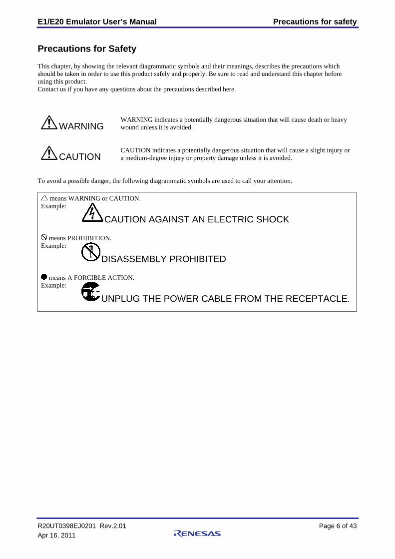
Precautions for Safety This chapter, by showing the relevant diagrammatic symbols and their meanings, describes the precautions which should be taken in order to use this product safely and properly. Be sure to read and understand this chapter before using this product. Contact us if you have any questions about the precautions described here.
WARNING
WARNING indicates a potentially dangerous situation that will cause death or heavy wound unless it is avoided.
CAUTION
CAUTION indicates a potentially dangerous situation that will cause a slight injury or a medium-degree injury or property damage unless it is avoided.
To avoid a possible danger, the following diagrammatic symbols are used to call your attention.
means WARNING or CAUTION. Example:
CAUTION AGAINST AN ELECTRIC SHOCK
means PROHIBITION. Example:
DISASSEMBLY PROHIBITED
means A FORCIBLE ACTION. Example:
UNPLUG THE POWER CABLE FROM THE RECEPTACLE.
R20UT0398EJ0201 Rev.2.01 Page 6 of 43 Apr 16, 2011
E1/E20 Emulator User’s Manual Precautions for safety
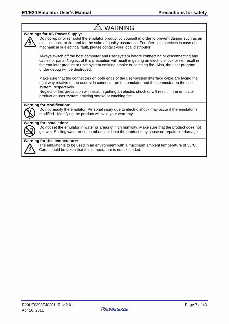
WARNING Warnings for AC Power Supply:
Do not repair or remodel the emulator product by yourself in order to prevent danger such as an electric shock or fire and for the sake of quality assurance. For after-sale services in case of a mechanical or electrical fault, please contact your local distributor. Always switch off the host computer and user system before connecting or disconnecting any cables or parts. Neglect of this precaution will result in getting an electric shock or will result in the emulator product or user system emitting smoke or catching fire. Also, the user program under debug will be destroyed. Make sure that the connectors on both ends of the user-system interface cable are facing the right way relative to the user-side connector on the emulator and the connector on the user system, respectively. Neglect of this precaution will result in getting an electric shock or will result in the emulator product or user system emitting smoke or catching fire.
Warning for Modification:
Do not modify the emulator. Personal injury due to electric shock may occur if the emulator is modified. Modifying the product will void your warranty.
Warning for Installation:
Do not set the emulator in water or areas of high humidity. Make sure that the product does not get wet. Spilling water or some other liquid into the product may cause un-repairable damage.
Warning for Use temperature:
The emulator is to be used in an environment with a maximum ambient temperature of 35°C. Care should be taken that this temperature is not exceeded.
R20UT0398EJ0201 Rev.2.01 Page 7 of 43 Apr 16, 2011
E1/E20 Emulator User’s Manual Precautions for safety
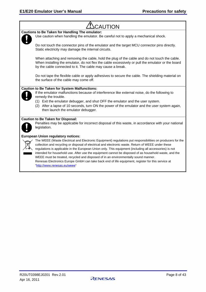
CAUTION Cautions to Be Taken for Handling The emulator:
Use caution when handling the emulator. Be careful not to apply a mechanical shock. Do not touch the connector pins of the emulator and the target MCU connector pins directly. Static electricity may damage the internal circuits. When attaching and removing the cable, hold the plug of the cable and do not touch the cable. When installing the emulator, do not flex the cable excessively or pull the emulator or the board by the cable connected to it. The cable may cause a break. Do not tape the flexible cable or apply adhesives to secure the cable. The shielding material on the surface of the cable may come off.
Caution to Be Taken for System Malfunctions:
If the emulator malfunctions because of interference like external noise, do the following to remedy the trouble. (1) Exit the emulator debugger, and shut OFF the emulator and the user system. (2) After a lapse of 10 seconds, turn ON the power of the emulator and the user system again,
then launch the emulator debugger.
Caution to Be Taken for Disposal:
Penalties may be applicable for incorrect disposal of this waste, in accordance with your national legislation.
European Union regulatory notices: The WEEE (Waste Electrical and Electronic Equipment) regulations put responsibilities on producers for the
collection and recycling or disposal of electrical and electronic waste. Return of WEEE under these regulations is applicable in the European Union only. This equipment (including all accessories) is not intended for household use. After use the equipment cannot be disposed of as household waste, and the WEEE must be treated, recycled and disposed of in an environmentally sound manner. Renesas Electronics Europe GmbH can take back end of life equipment, register for this service at “http://www.renesas.eu/weee“
R20UT0398EJ0201 Rev.2.01 Page 8 of 43 Apr 16, 2011
E1/E20 Emulator User’s Manual Contents
R20UT0398EJ0201 Rev.2.01 Page 9 of 43 Apr 16, 2011
Contents Page Preface ............................................................................................................................................................................... 3 Important ........................................................................................................................................................................... 4 Precautions for Safety........................................................................................................................................................ 6 User Registration ............................................................................................................................................................. 10 Terminology .................................................................................................................................................................... 11 1. Outline ......................................................................................................................................................................... 12
1.1 Package Components....................................................................................................................................... 12 1.2 System Configuration ...................................................................................................................................... 13 1.3 PC Interface ..................................................................................................................................................... 13 1.4 Specifications................................................................................................................................................... 14 1.5 Regulatory Compliance Notices ...................................................................................................................... 15 1.6 Emulator Hardware Configuration .................................................................................................................. 16 1.7 The Names of the Emulator Parts .................................................................................................................... 17 1.8 Operating Environment.................................................................................................................................... 19
2. Setup ............................................................................................................................................................................ 20 2.1 Installing Emulator Software ........................................................................................................................... 20 2.2 Connecting the Emulator to the Host Computer .............................................................................................. 20 2.3 Connecting the Emulator to the User System .................................................................................................. 21 2.4 Connecting System Ground ............................................................................................................................. 25
3. Troubleshooting (Action in Case of an Error) ............................................................................................................. 26 3.1 How to Solve a Trouble ................................................................................................................................... 26 3.2 How to Request Support .................................................................................................................................. 26
4. Maintenance and Warranty.......................................................................................................................................... 27 4.1 User Registration ............................................................................................................................................. 27 4.2 Maintenance..................................................................................................................................................... 27 4.3 Warranty .......................................................................................................................................................... 27 4.4 Repair Provisions............................................................................................................................................. 28 4.5 How to Make Request for Repair .................................................................................................................... 28
Appendix A Self-Checking Program (SCP) .................................................................................................................. 29 A.1 Flow of Self-Checking..................................................................................................................................... 29 A.2 Preparations for Self-Checking........................................................................................................................ 30 A.3 Executing the Self-Checking Program............................................................................................................. 31
E1/E20 Emulator User’s Manual User Registration
R20UT0398EJ0201 Rev.2.01 Page 10 of 43 Apr 16, 2011
User Registration When you install debugger software, a text file for user registration is created on your PC. Fill it in and email it to your local distributor. If you have replaced an emulator main unit or emulation probe, rewrite an emulator name and serial number in the text file you filled in earlier to register your new hardware products. Your registered information is used for only after-sale services, and not for any other purposes. Without user registration, you will not be able to receive maintenance services such as a notification of field changes or trouble information. So be sure to carry out the user registration. For more information about user registration, please contact your local distributor.
E1/E20 Emulator User’s Manual Terminology
R20UT0398EJ0201 Rev.2.01 Page 11 of 43 Apr 16, 2011
Terminology Some specific words used in this user's manual are defined below. Integrated development environment: High-performance Embedded Workshop This tool provides powerful support for the development of embedded applications for Renesas microcomputers. It has an emulator debugger function allowing the emulator to be controlled from the host machine via an interface. Furthermore, it permits a range of operations from editing a project to building and debugging it to be performed within the same application. In addition, it supports version management. Emulator debugger This means a software tool that is started up from the High-performance Embedded Workshop, and controls the emulator and enables debugging.
Host machine This means a personal computer used to control the emulator.
Target MCU This means the MCU to be debugged.
User system This means a user's application system in which the MCU to be debugged is used.
User program This means the program to be debugged.
E1/E20 Emulator User’s Manual 1.Outline
R20UT0398EJ0201 Rev.2.01 Page 12 of 43 Apr 16, 2011
1. Outline This chapter describes the package components, the system configuration, and the specifications of the emulator functions and operating environment.
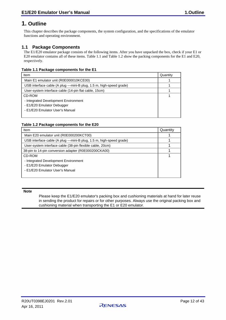
1.1 Package Components The E1/E20 emulator package consists of the following items. After you have unpacked the box, check if your E1 or E20 emulator contains all of these items. Table 1.1 and Table 1.2 show the packing components for the E1 and E20, respectively.
Table 1.1 Package components for the E1 Item Quantity Main E1 emulator unit (R0E000010KCE00) 1 USB interface cable (A plug —mini-B plug, 1.5 m, high-speed grade) 1 User-system interface cable (14-pin flat cable, 15cm) 1 CD-ROM - Integrated Development Environment - E1/E20 Emulator Debugger - E1/E20 Emulator User’s Manual
1
Table 1.2 Package components for the E20 Item Quantity Main E20 emulator unit (R0E000200KCT00) 1 USB interface cable (A plug —mini-B plug, 1.5 m, high-speed grade) 1 User-system interface cable (38-pin flexible cable, 20cm) 1 38-pin to 14-pin conversion adapter (R0E000200CKA00) 1 CD-ROM - Integrated Development Environment - E1/E20 Emulator Debugger - E1/E20 Emulator User’s Manual
1
Note Please keep the E1/E20 emulator's packing box and cushioning materials at hand for later reuse
in sending the product for repairs or for other purposes. Always use the original packing box and cushioning material when transporting the E1 or E20 emulator.
E1/E20 Emulator User’s Manual 1.Outline
1.2 System Configuration
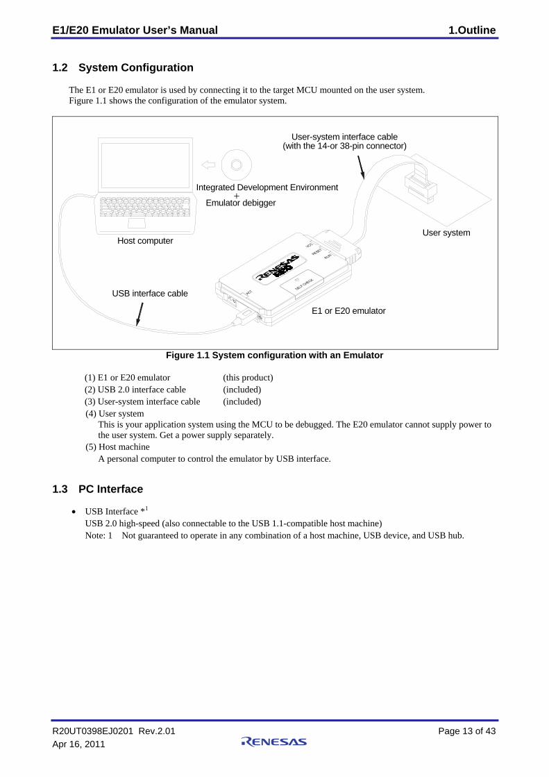
The E1 or E20 emulator is used by connecting it to the target MCU mounted on the user system. Figure 1.1 shows the configuration of the emulator system.
Emulator debigger
Integrated Development Environment+
(with the 14-or 38-pin connector)User-system interface cable
User system
USB interface cable
E1 or E20 emulator
Host computer
Figure 1.1 System configuration with an Emulator (1) E1 or E20 emulator (this product) (2) USB 2.0 interface cable (included) (3) User-system interface cable (included) (4) User system
This is your application system using the MCU to be debugged. The E20 emulator cannot supply power to the user system. Get a power supply separately.
(5) Host machine A personal computer to control the emulator by USB interface.
1.3 PC Interface
• USB Interface *1 USB 2.0 high-speed (also connectable to the USB 1.1-compatible host machine) Note: 1 Not guaranteed to operate in any combination of a host machine, USB device, and USB hub.
R20UT0398EJ0201 Rev.2.01 Page 13 of 43 Apr 16, 2011
E1/E20 Emulator User’s Manual 1.Outline
R20UT0398EJ0201 Rev.2.01 Page 14 of 43 Apr 16, 2011
1.4 Specifications
1.4.1 Product Specifications
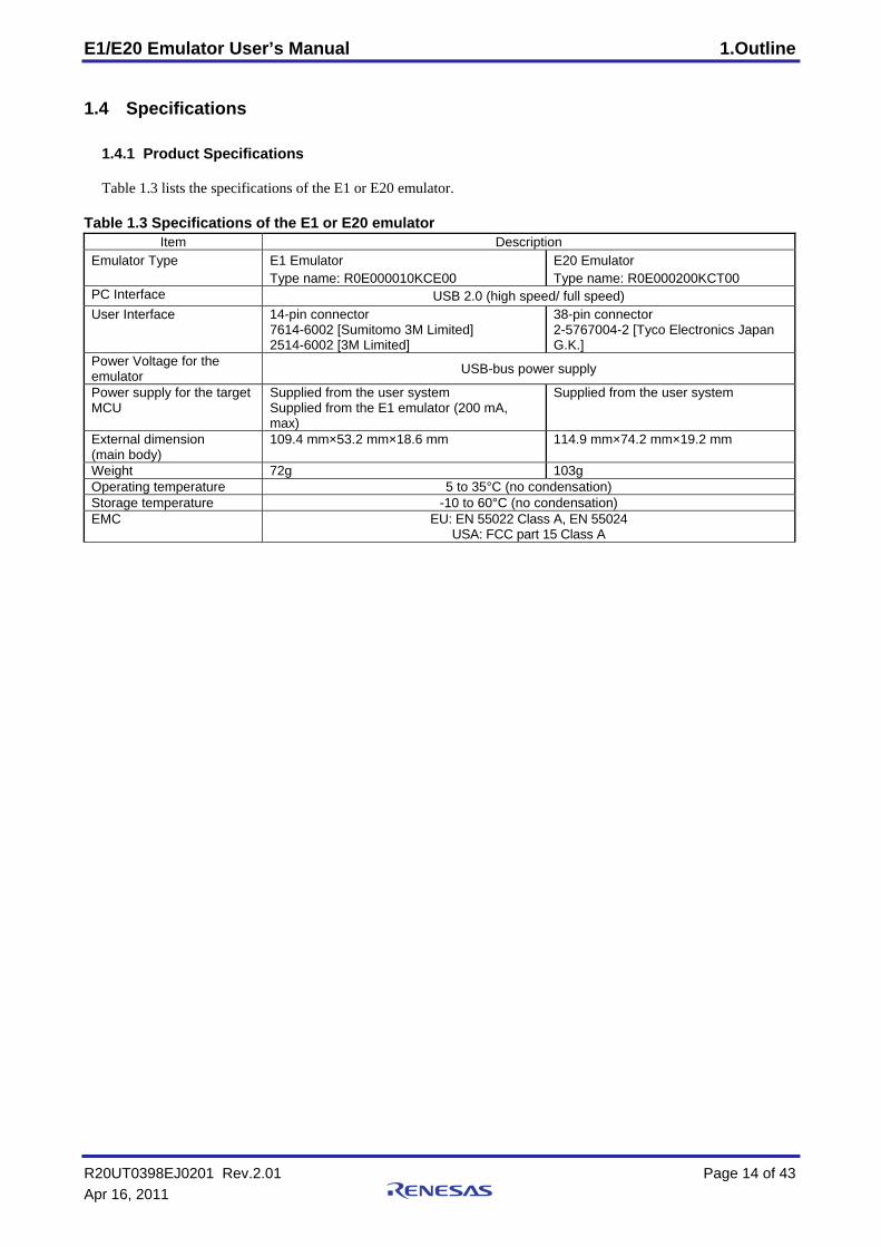
Table 1.3 lists the specifications of the E1 or E20 emulator. Table 1.3 Specifications of the E1 or E20 emulator
Item Description Emulator Type E1 Emulator
Type name: R0E000010KCE00 E20 Emulator Type name: R0E000200KCT00
PC Interface USB 2.0 (high speed/ full speed) User Interface 14-pin connector
7614-6002 [Sumitomo 3M Limited] 2514-6002 [3M Limited]
38-pin connector 2-5767004-2 [Tyco Electronics Japan G.K.]
Power Voltage for the emulator USB-bus power supply
Power supply for the target MCU
Supplied from the user system Supplied from the E1 emulator (200 mA, max)
Supplied from the user system
External dimension (main body)
109.4 mm×53.2 mm×18.6 mm 114.9 mm×74.2 mm×19.2 mm
Weight 72g 103g Operating temperature 5 to 35°C (no condensation) Storage temperature -10 to 60°C (no condensation) EMC EU: EN 55022 Class A, EN 55024
USA: FCC part 15 Class A
E1/E20 Emulator User’s Manual 1.Outline
R20UT0398EJ0201 Rev.2.01 Page 15 of 43 Apr 16, 2011
1.5 Regulatory Compliance Notices 1.5.1 European Union regulatory notices
This product complies with the following EU Directives. (These directives are only valid in the European Union.) CE Certifications: ・Electromagnetic Compatibility (EMC) Directive 2004/108/EC
EN 55022 Class A
WARNING: This is a Class A product. In a domestic environment this product may cause radio interference in which case the user may be required to take adequate measures. EN 55024
・Information for traceability
・Authorised representative Name: Renesas Electronics Corporation Address: 1753, Shimonumabe, Nakahara-ku, Kawasaki, Kanagawa, 211-8668, Japan
・Manufacturer Name: Renesas Solutions Corp. Address: Nippon Bldg., 2-6-2, Ote-machi, Chiyoda-ku, Tokyo 100-0004, Japan
・Person responsible for placing on the market Name: Renesas Electronics Europe Limited Address: Dukes Meadow, Millboard Road, Bourne End, Buckinghamshire, SL8 5FH, U.K.
・Trademark and Type name Trademark: Renesas Product name: E1 Emulator / E20 Emulator Type name: R0E000010KCE00 / R0E000200KCT00
Environmental Compliance and Certifications: ・Restriction of the Use of Certain Hazardous Substances in Electrical and Electronic Equipment (RoHS)
Directive 2002/95/EC ・Waste Electrical and Electronic Equipment (WEEE) Directive 2002/96/EC
United States Regulatory notices on Electromagnetic compatibility
FCC Certifications (United States Only): This equipment has been tested and found to comply with the limits for a Class A digital device, pursuant to Part 15 of the FCC Rules. These limits are designed to provide reasonable protection against harmful interference when the equipment is operated in a commercial environment. This equipment generates, uses, and can radiate radio frequency energy and, if not installed and used in accordance with the instruction manual, may cause harmful interference to radio communications. Operation of this equipment in a residential area is likely to cause harmful interference in which case the user will be required to correct the interference at his own expense. This device complies with Part 15 of the FCC Rules. Operation is subject to the following two conditions: (1) this device may not cause harmful interference, and (2) this device must accept any interference received, including interference that may cause undesired operation. CAUTION: Changes or modifications not expressly approved by the party responsible for
compliance could void the user's authority to operate the equipment.
E1/E20 Emulator User’s Manual 1.Outline
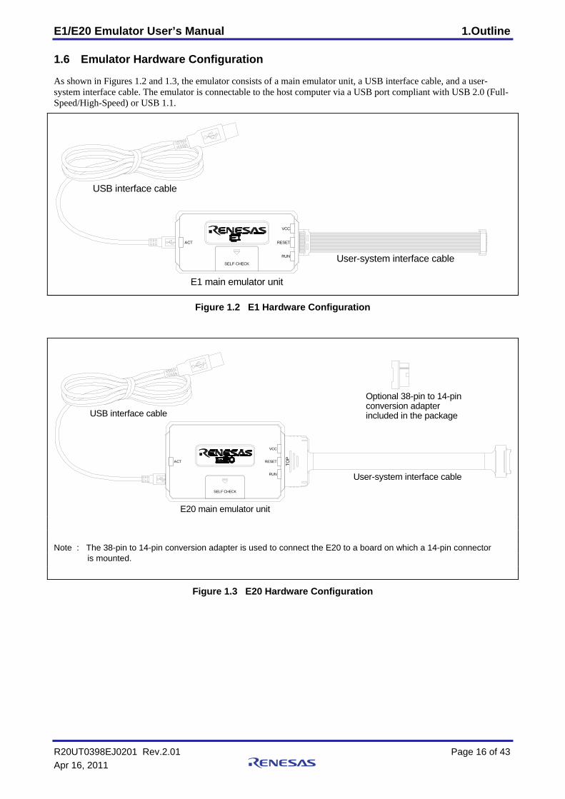
1.6 Emulator Hardware Configuration
As shown in Figures 1.2 and 1.3, the emulator consists of a main emulator unit, a USB interface cable, and a user-system interface cable. The emulator is connectable to the host computer via a USB port compliant with USB 2.0 (Full-Speed/High-Speed) or USB 1.1.
User-system interface cable
E1 main emulator unit
USB interface cable
RESET
VCC
RUN
ACT
SELF CHECK
Figure 1.2 E1 Hardware Configuration
included in the packageconversion adapterOptional 38-pin to 14-pin
TOP
RESET
RUN
VCC
ACT
SELF CHECK
User-system interface cable
E20 main emulator unit
USB interface cable
Note : The 38-pin to 14-pin conversion adapter is used to connect the E20 to a board on which a 14-pin connector
is mounted.
Figure 1.3 E20 Hardware Configuration
R20UT0398EJ0201 Rev.2.01 Page 16 of 43 Apr 16, 2011
E1/E20 Emulator User’s Manual 1.Outline
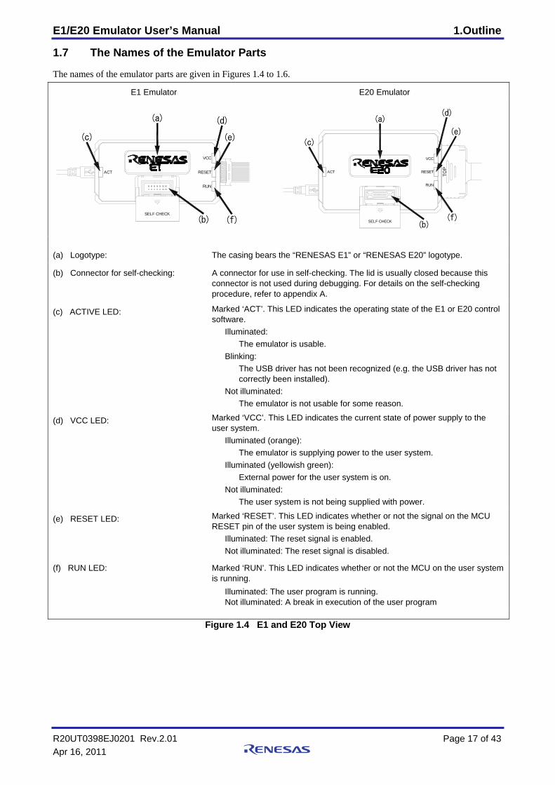
1.7 The Names of the Emulator Parts
The names of the emulator parts are given in Figures 1.4 to 1.6.
E1 Emulator E20 Emulator
ACT
(c)
(b)
RUN
VCC
RESET
SELF CHECK
(f)
(a) (d)
(e)
(c)
(f)
(d)
TOP
SELF CHECK
ACT
(b)
RUN
RESET
(a)
VCC
(e)
(a) Logotype: The casing bears the “RENESAS E1” or “RENESAS E20” logotype.
(b) Connector for self-checking: A connector for use in self-checking. The lid is usually closed because this connector is not used during debugging. For details on the self-checking procedure, refer to appendix A.
(c) ACTIVE LED: Marked ‘ACT’. This LED indicates the operating state of the E1 or E20 control software.
Illuminated: The emulator is usable.
Blinking: The USB driver has not been recognized (e.g. the USB driver has not correctly been installed).
Not illuminated: The emulator is not usable for some reason.
(d) VCC LED: Marked ‘VCC’. This LED indicates the current state of power supply to the user system.
Illuminated (orange): The emulator is supplying power to the user system.
Illuminated (yellowish green): External power for the user system is on.
Not illuminated: The user system is not being supplied with power.
(e) RESET LED: Marked ‘RESET’. This LED indicates whether or not the signal on the MCU RESET pin of the user system is being enabled.
Illuminated: The reset signal is enabled. Not illuminated: The reset signal is disabled.
(f) RUN LED: Marked ‘RUN’. This LED indicates whether or not the MCU on the user system is running.
Illuminated: The user program is running. Not illuminated: A break in execution of the user program
Figure 1.4 E1 and E20 Top View
R20UT0398EJ0201 Rev.2.01 Page 17 of 43 Apr 16, 2011
E1/E20 Emulator User’s Manual 1.Outline
E1 Emulator E20 Emulator
(a)
(b)
(c)
OI
(a) (b)
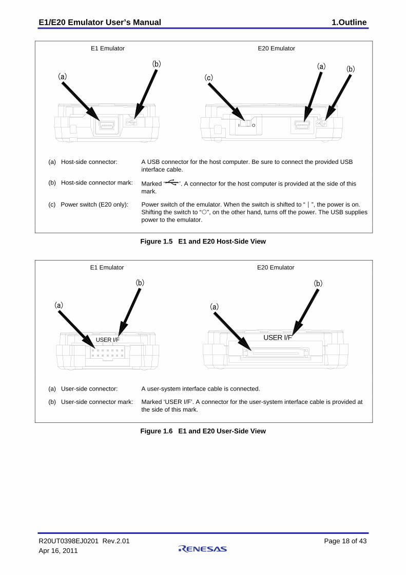
(a) Host-side connector: A USB connector for the host computer. Be sure to connect the provided USB interface cable.
(b) Host-side connector mark: Marked ‘ ’. A connector for the host computer is provided at the side of this mark.
(c) Power switch (E20 only): Power switch of the emulator. When the switch is shifted to “|”, the power is on. Shifting the switch to “ ”, on the other hand, turns off the power. The USB supplies power to the emulator.
Figure 1.5 E1 and E20 Host-Side View
E1 Emulator E20 Emulator
(a)
(b)
USER I/F
(b)
(a)
USER I/F
(a) User-side connector: A user-system interface cable is connected.
(b) User-side connector mark: Marked ‘USER I/F’. A connector for the user-system interface cable is provided at the side of this mark.
Figure 1.6 E1 and E20 User-Side View
R20UT0398EJ0201 Rev.2.01 Page 18 of 43 Apr 16, 2011
E1/E20 Emulator User’s Manual 1.Outline
R20UT0398EJ0201 Rev.2.01 Page 19 of 43 Apr 16, 2011
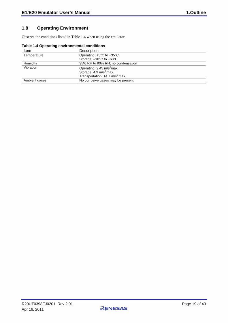
1.8 Operating Environment
Observe the conditions listed in Table 1.4 when using the emulator. Table 1.4 Operating environmental conditions Item Description Temperature Operating: +5°C to +35°C
Storage: –10°C to +60°C Humidity 35% RH to 80% RH, no condensation Vibration Operating: 2.45 m/s2max.
Storage: 4.9 m/s2 max.
Transportation: 14.7 m/s2 max.
Ambient gases No corrosive gases may be present
E1/E20 Emulator User’s Manual 2.Setup
2. Setup 2.1 Installing Emulator Software
Execute README.HTM from the root directory of the installation medium and follow the cues shown on screen to install the software. Note: When a driver is installed in Windows®
2000, Windows® XP, Windows Vista®, or Windows® 7 a warning
message on the Windows® logo test may be displayed, but it is not a problem.
Select [Continue Anyway] to proceed with driver installation.
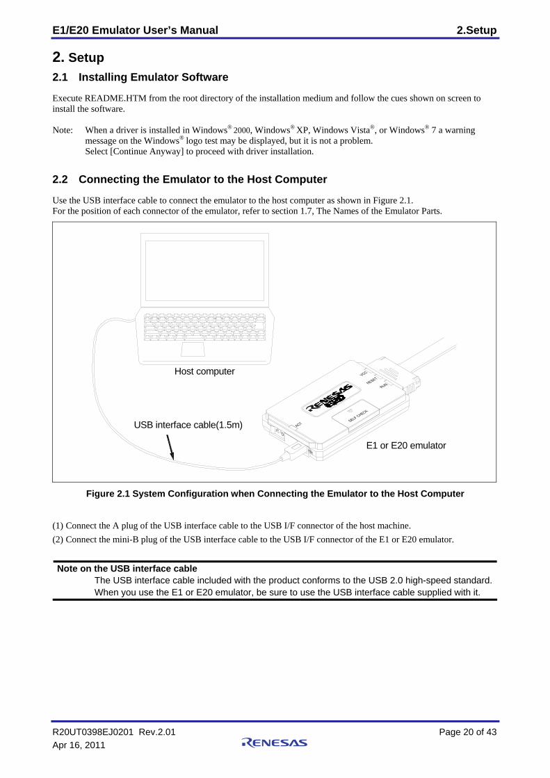
2.2 Connecting the Emulator to the Host Computer
Use the USB interface cable to connect the emulator to the host computer as shown in Figure 2.1. For the position of each connector of the emulator, refer to section 1.7, The Names of the Emulator Parts.
E1 or E20 emulator
USB interface cable(1.5m)
Host computer
Figure 2.1 System Configuration when Connecting the Emulator to the Host Computer
(1) Connect the A plug of the USB interface cable to the USB I/F connector of the host machine. (2) Connect the mini-B plug of the USB interface cable to the USB I/F connector of the E1 or E20 emulator.
Note on the USB interface cable The USB interface cable included with the product conforms to the USB 2.0 high-speed standard.
When you use the E1 or E20 emulator, be sure to use the USB interface cable supplied with it.
R20UT0398EJ0201 Rev.2.01 Page 20 of 43 Apr 16, 2011
E1/E20 Emulator User’s Manual 2.Setup
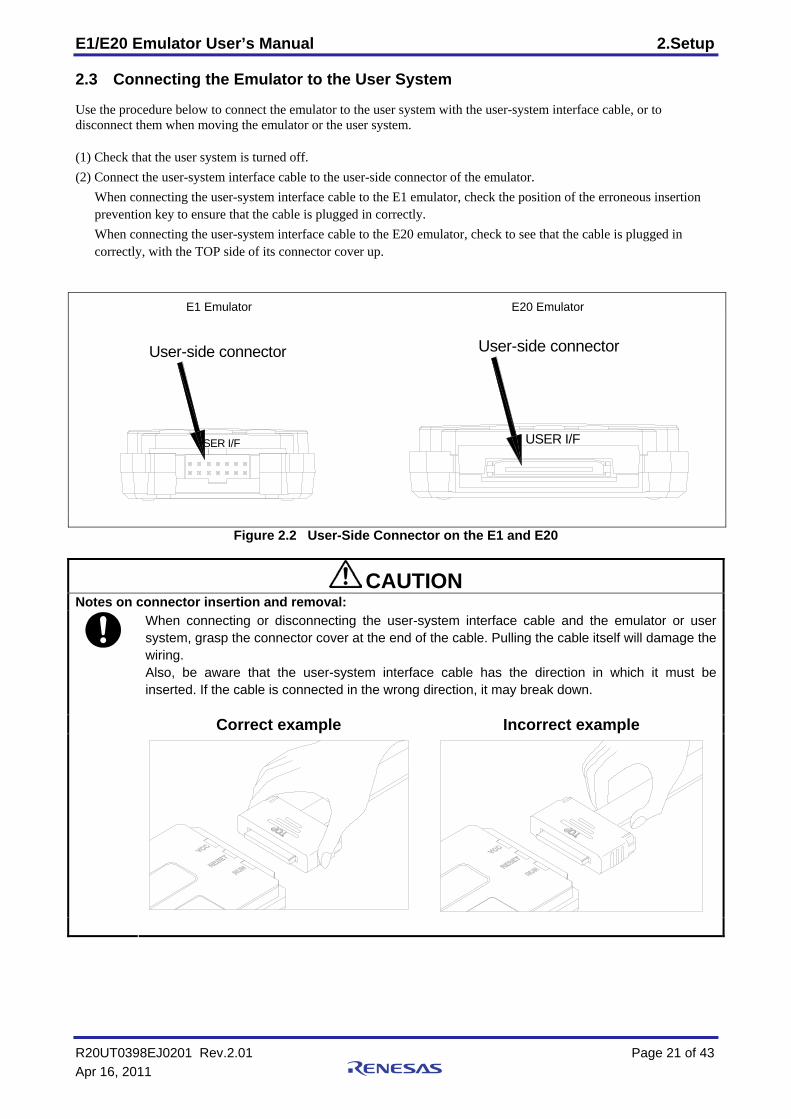
2.3 Connecting the Emulator to the User System
Use the procedure below to connect the emulator to the user system with the user-system interface cable, or to disconnect them when moving the emulator or the user system. (1) Check that the user system is turned off. (2) Connect the user-system interface cable to the user-side connector of the emulator. When connecting the user-system interface cable to the E1 emulator, check the position of the erroneous insertion
prevention key to ensure that the cable is plugged in correctly. When connecting the user-system interface cable to the E20 emulator, check to see that the cable is plugged in
correctly, with the TOP side of its connector cover up.
E1 Emulator E20 Emulator
User-side connector
USER I/F
User-side connector
USER I/F
Figure 2.2 User-Side Connector on the E1 and E20
CAUTION Notes on connector insertion and removal:
When connecting or disconnecting the user-system interface cable and the emulator or user system, grasp the connector cover at the end of the cable. Pulling the cable itself will damage the wiring. Also, be aware that the user-system interface cable has the direction in which it must be inserted. If the cable is connected in the wrong direction, it may break down.
Correct example Incorrect example
R20UT0398EJ0201 Rev.2.01 Page 21 of 43 Apr 16, 2011

E1/E20 Emulator User’s Manual 2.Setup
(1) A connector to the user-system interface cable must be installed on the user system. Table 2.1 shows the recommended connector for the emulator.
Table 2.1 Recommended Connector
Connector Type Number Manufacturer Specifications 7614-6002 Sumitomo 3M Limited 14-pin straight type
(Japan) 14-pin connector
2514-6002 3M Limited 14-pin straight type (other countries)
38-pin connector 2-5767004-2 Tyco Electronics Japan G.K. 38-pin type (2) For the pin assignments of the connector, refer to the separate MCU-specific manual for the emulator. (3) Connect one end of the user-system interface cable to the emulator and the other end to the connector on the user
system as shown in Figures 2.3, 2.4, and 2.5.
CAUTION Notes on connector insertion and removal:
When connecting or disconnecting the user-system interface cable and the emulator or user system, grasp the connector cover at the end of the cable. Pulling the cable itself will damage the wiring.
Correct example Incorrect example
14-pin user-system interface cable
14-pin connector7614-6002 or2514-6002
User system
Pin 1
Pin 2
Figure 2.3 Connecting the User-System Interface Cable to the User System when the 14-Pin Connector is in Use with the E1
R20UT0398EJ0201 Rev.2.01 Page 22 of 43 Apr 16, 2011
E1/E20 Emulator User’s Manual 2.Setup
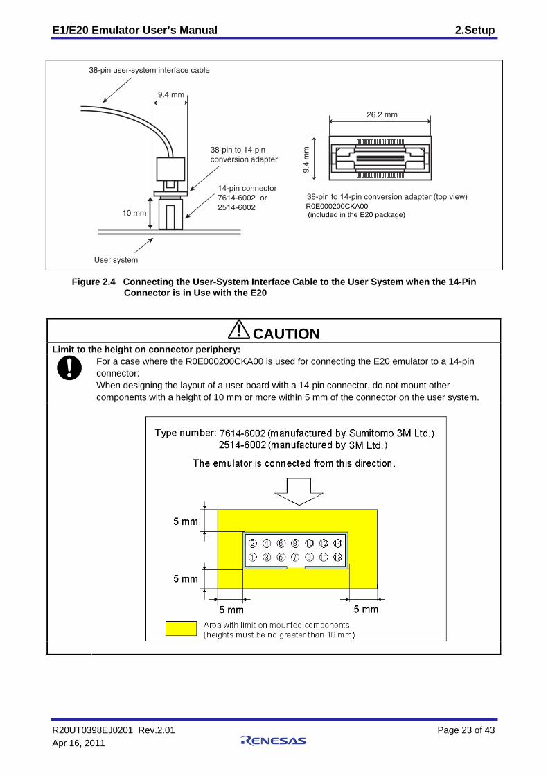
10 mm
User system
38-pin user-system interface cable
26.2 mm
9.4
mm38-pin to 14-pin
conversion adapter
9.4 mm
14-pin connector 7614-6002 or 2514-6002
38-pin to 14-pin conversion adapter (top view)
R0E000200CKA00 (included in the E20 package)
Figure 2.4 Connecting the User-System Interface Cable to the User System when the 14-Pin Connector is in Use with the E20
CAUTION Limit to the height on connector periphery:
For a case where the R0E000200CKA00 is used for connecting the E20 emulator to a 14-pin connector: When designing the layout of a user board with a 14-pin connector, do not mount other components with a height of 10 mm or more within 5 mm of the connector on the user system.
R20UT0398EJ0201 Rev.2.01 Page 23 of 43 Apr 16, 2011
E1/E20 Emulator User’s Manual 2.Setup
Connector (top view)
5 mm
User system
38-pin user-system interface cable
38-pin connector2-5767004-2
30 mm
15 m
m
137
38 2
: Area with limit on mounted components
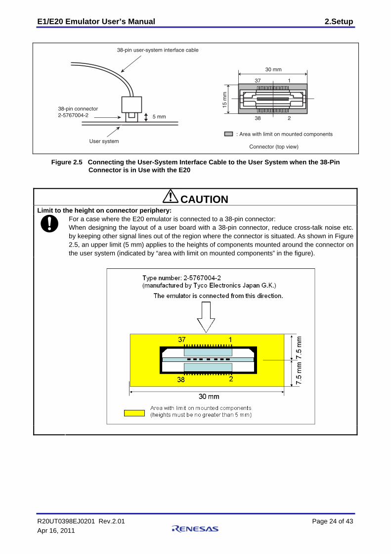
Figure 2.5 Connecting the User-System Interface Cable to the User System when the 38-Pin Connector is in Use with the E20
CAUTION Limit to the height on connector periphery:
For a case where the E20 emulator is connected to a 38-pin connector: When designing the layout of a user board with a 38-pin connector, reduce cross-talk noise etc. by keeping other signal lines out of the region where the connector is situated. As shown in Figure 2.5, an upper limit (5 mm) applies to the heights of components mounted around the connector on the user system (indicated by “area with limit on mounted components” in the figure).
R20UT0398EJ0201 Rev.2.01 Page 24 of 43 Apr 16, 2011
E1/E20 Emulator User’s Manual 2.Setup
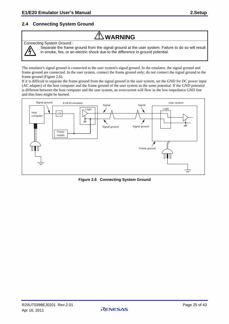
2.4 Connecting System Ground
WARNING Connecting System Ground :
Separate the frame ground from the signal ground at the user system. Failure to do so will result in smoke, fire, or an electric shock due to the difference in ground potential.
The emulator's signal ground is connected to the user system's signal ground. In the emulator, the signal ground and frame ground are connected. In the user system, connect the frame ground only; do not connect the signal ground to the frame ground (Figure 2.6). If it is difficult to separate the frame ground from the signal ground in the user system, set the GND for DC power input (AC adapter) of the host computer and the frame ground of the user system as the same potential. If the GND potential is different between the host computer and the user system, an overcurrent will flow in the low-impedance GND line and thin lines might be burned.
USB
E1/E20 emulator
Logic Logic
Power supply
Hostcomputer
Signal ground
Signal groundSignal
Signal ground
Signal
Frame ground
User system
Figure 2.6 Connecting System Ground
R20UT0398EJ0201 Rev.2.01 Page 25 of 43 Apr 16, 2011
E1/E20 Emulator User’s Manual 3.Troubleshooting
R20UT0398EJ0201 Rev.2.01 Page 26 of 43 Apr 16, 2011
3. Troubleshooting (Action in Case of an Error)
3.1 How to Solve a Trouble The following describes how to solve a trouble when any problem occurs before the emulator debugger starts after the emulator and the user system have been powered on. For the latest information on the emulator and emulator debugger, visit Renesas Electronics’ development environment website (http://www.renesas.com/tools).
3.1.1 ACTION LED does not light (1) Keeps flashing The USB driver is not installed correctly in the host machine. Install the USB driver correctly.
(2) Remains off This means that the E1 or E20 is in an unusable state for some reason. Check the following: • Whether the E1 or E20 and the host machine are connected with the USB interface cable. • Whether the power switch of the E20 is turned on. • Whether the power for the host machine is turned on.
3.1.2 Unconnectable with the debugger (1) Check the connection between the emulator and the MCU. For details, consult the separate E1/E20 manual for the MCU you’re using. • Whether the emulator and the MCU are connected correctly. • Whether the connected signal lines are pulled up to the power supply or down to GND properly. (2) Check to see that the MCU is in a ready state. • The MCU operating clock is on (= oscillating). • The MCU is supplied with power properly. • The MCU has been reset and is ready to go.
3.2 How to Request Support After checking the items in "3 Troubleshooting", contact us from the following URL.
http://www.renesas.com/inquiry
For prompt response, please specify the following information: (1) Operating environment
- MCU name: - Operating frequency: [MHz] - MCU operating mode: [Mode] - Clock supply to the MCU: Emulator/User-system
(2) Condition - The emulator debugger starts up/does not start up - The error is detected/not detected in the self-check - Frequency of errors: always/frequency ( )
(3) Problem
E1/E20 Emulator User’s Manual 4.Maintenance and Warranty
R20UT0398EJ0201 Rev.2.01 Page 27 of 43 Apr 16, 2011
4. Maintenance and Warranty
This chapter covers basic maintenance, warranty information, provisions for repair and the procedures for requesting a repair.
4.1 User Registration When you purchase our product, be sure to register as a user. For user registration, refer to “User Registration” (page 10) of this user's manual.
4.2 Maintenance (1) If dust or dirt collects on this product, wipe it off with a dry soft cloth. Do not use thinner or other solvents because
these chemicals can cause the surface coating to separate. (2) When you do not use this product for a long period, disconnect it from the power supply, host machine and user
system.
4.3 Warranty 1. This product comes with a one-year limited warranty after purchase. Should the product break down or be damaged while you’re using it under normal condition based on its user’s
manual, it will be repaired or replaced free of cost. 2. However, if the following failure or damage occurs to the product under warranty, the product will be repaired
or replaced at cost. a) Failure or damage attributable to the misuse or abuse of the product or its use under other abnormal
conditions. b) Failure or damage attributable to improper handling of the product after purchase, such as dropping of the
product when it is transported or moved. c) Failure or damage to the product caused by other pieces of equipment connected to it. d) Failure or damage attributable to fire, earthquakes, thunderbolts, floods, or other natural disasters or
abnormal voltages, etc. e) Failure or damage attributable to modifications, repairs, adjustments, or other acts made to the product by
other than Renesas Electronics Corporation.
3. Consumables (e.g., sockets and adapters) are not covered by the aforementioned repair.
In the above cases, contact your local distributor. If your product is being leased, consult the leasing company or the owner.
E1/E20 Emulator User’s Manual 4.Maintenance and Warranty
4.4 Repair Provisions (1) Repairs not covered by warranty
Problems arising in products for which more than one year has elapsed since purchase are not covered by warranty.
(2) Replacement not covered by warranty If your product's fault falls into any of the following categories, the fault will be corrected by replacing the entire product instead of repairing it, or you will be advised to purchase a new product, depending on the severity of the fault. - Faulty or broken mechanical portions - Flaws, separation, or rust in coated or plated portions - Flaws or cracks in plastic portions - Faults or breakage caused by improper use or unauthorized repair or modification - Heavily damaged electric circuits due to overvoltage, overcurrent or shorting of power supply - Cracks in the printed circuit board or burnt-down patterns - A wide range of faults that make replacement less expensive than repair - Faults that are not locatable or identifiable
(3) Expiration of the repair period
When a period of one year has elapsed after production of a given model ceased, repairing products of that model may become impossible.
(4) Carriage fees for sending your product to be repaired
Carriage fees for sending your product to us for repair are at your own expense.
4.5 How to Make Request for Repair If your product is found faulty, fill in a Repair Request Sheet downloadable from the following URL. And email the sheet and send the product to your local distributor.
http://www.renesas.com/repair
CAUTION Note on Transporting the Product:
When sending your product for repair, use the packing box and cushioning material supplied with the product when it was delivered to you and specify caution in handling (handling as precision equipment). If packing of your product is not complete, it may be damaged during transportation. When you pack your product in a bag, make sure to use the conductive plastic bag supplied with the product (usually a blue bag). If you use a different bag, it may lead to further trouble with your product due to static electricity.
R20UT0398EJ0201 Rev.2.01 Page 28 of 43 Apr 16, 2011
E1/E20 Emulator User’s Manual Appendix A
Appendix A Self-Checking Program (SCP) This section gives the procedure for using the self-checking program for the E1 and E20 in fault analysis.
A.1 Flow of Self-Checking
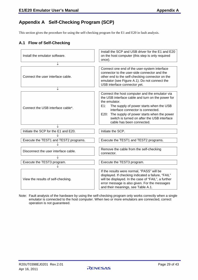
Install the emulator software. Install the SCP and USB driver for the E1 and E20 on the host computer (this step is only required once).
↓
Connect the user interface cable.
Connect one end of the user-system interface connector to the user-side connector and the other end to the self-checking connector on the emulator (see Figure A.1). Do not connect the USB interface connector yet.
↓
Connect the USB interface cable*.
Connect the host computer and the emulator via the USB interface cable and turn on the power for the emulator. E1: The supply of power starts when the USB
interface connector is connected. E20: The supply of power starts when the power
switch is turned on after the USB interface cable has been connected.
↓
Initiate the SCP for the E1 and E20. Initiate the SCP.
↓
Execute the TEST1 and TEST2 programs. Execute the TEST1 and TEST2 programs.
↓
Disconnect the user interface cable. Remove the cable from the self-checking connector.
↓
Execute the TEST3 program. Execute the TEST3 program.
↓
View the results of self-checking.
If the results were normal, “PASS” will be displayed. If checking indicated a failure, “FAIL” will be displayed. In the case of “FAIL”, a further error message is also given. For the messages and their meanings, see Table A.1.
Note: Fault analysis of the hardware by using the self-checking program only works correctly when a single
emulator is connected to the host computer. When two or more emulators are connected, correct operation is not guaranteed.
R20UT0398EJ0201 Rev.2.01 Page 29 of 43 Apr 16, 2011
E1/E20 Emulator User’s Manual Appendix A
A.2 Preparations for Self-Checking
(1) The following items are required to execute the self-checking program. • E1 or E20 emulator • USB interface cable (included in the package) • User interface cable (included in the package) • Installation medium (included in the package) • Host computer
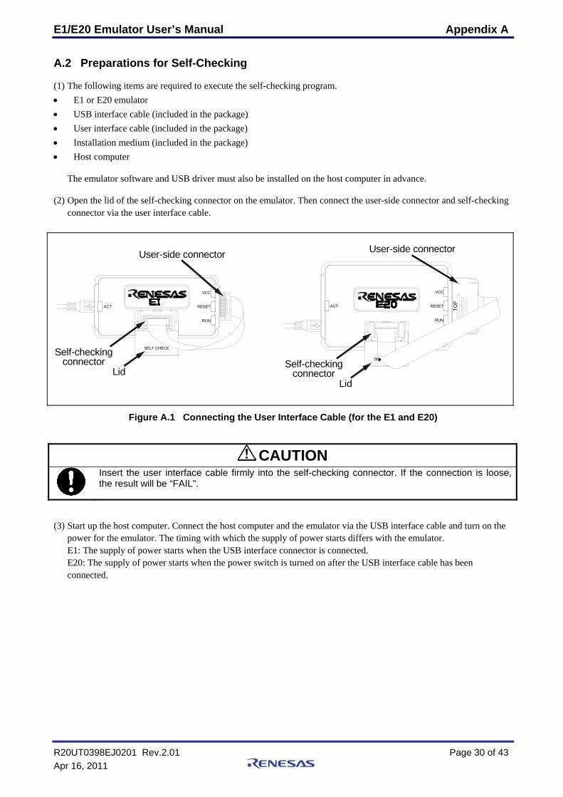
The emulator software and USB driver must also be installed on the host computer in advance. (2) Open the lid of the self-checking connector on the emulator. Then connect the user-side connector and self-checking
connector via the user interface cable.
connectorconnector
Self-checking
Lid
User-side connector User-side connector
Lid
Self-checking
RUN
VCC
RESETACT
SE
RUN
SELF CHECK
VCC
RESETACT TOP
Figure A.1 Connecting the User Interface Cable (for the E1 and E20)
CAUTION
Insert the user interface cable firmly into the self-checking connector. If the connection is loose, the result will be “FAIL”.
(3) Start up the host computer. Connect the host computer and the emulator via the USB interface cable and turn on the
power for the emulator. The timing with which the supply of power starts differs with the emulator. E1: The supply of power starts when the USB interface connector is connected. E20: The supply of power starts when the power switch is turned on after the USB interface cable has been connected.
R20UT0398EJ0201 Rev.2.01 Page 30 of 43 Apr 16, 2011
E1/E20 Emulator User’s Manual Appendix A
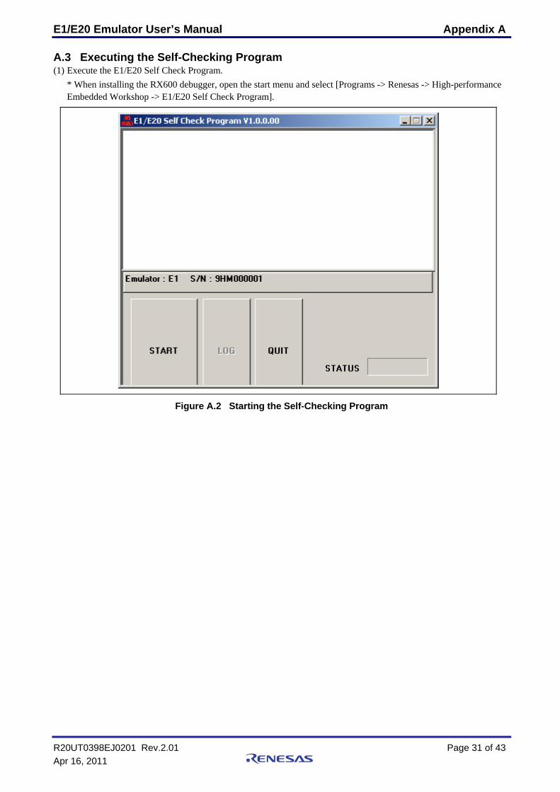
A.3 Executing the Self-Checking Program (1) Execute the E1/E20 Self Check Program.
* When installing the RX600 debugger, open the start menu and select [Programs -> Renesas -> High-performance Embedded Workshop -> E1/E20 Self Check Program].
Figure A.2 Starting the Self-Checking Program
R20UT0398EJ0201 Rev.2.01 Page 31 of 43 Apr 16, 2011
E1/E20 Emulator User’s Manual Appendix A
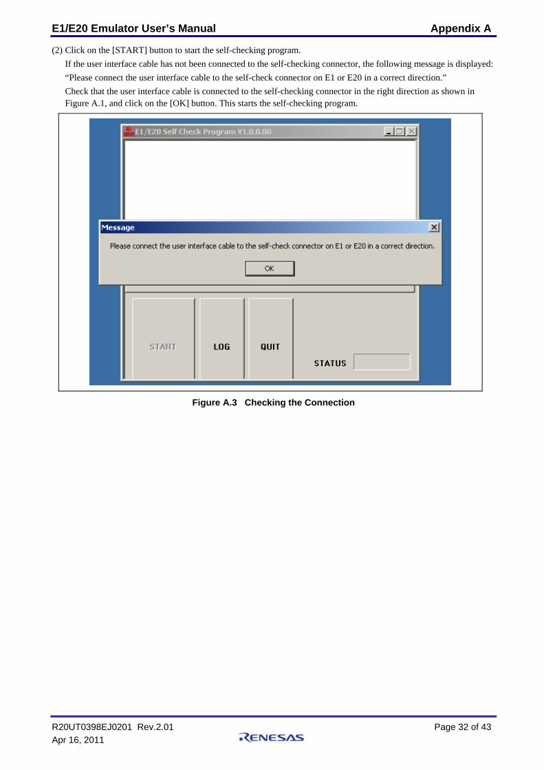
(2) Click on the [START] button to start the self-checking program. If the user interface cable has not been connected to the self-checking connector, the following message is displayed: “Please connect the user interface cable to the self-check connector on E1 or E20 in a correct direction.” Check that the user interface cable is connected to the self-checking connector in the right direction as shown in Figure A.1, and click on the [OK] button. This starts the self-checking program.
Figure A.3 Checking the Connection
R20UT0398EJ0201 Rev.2.01 Page 32 of 43 Apr 16, 2011
E1/E20 Emulator User’s Manual Appendix A
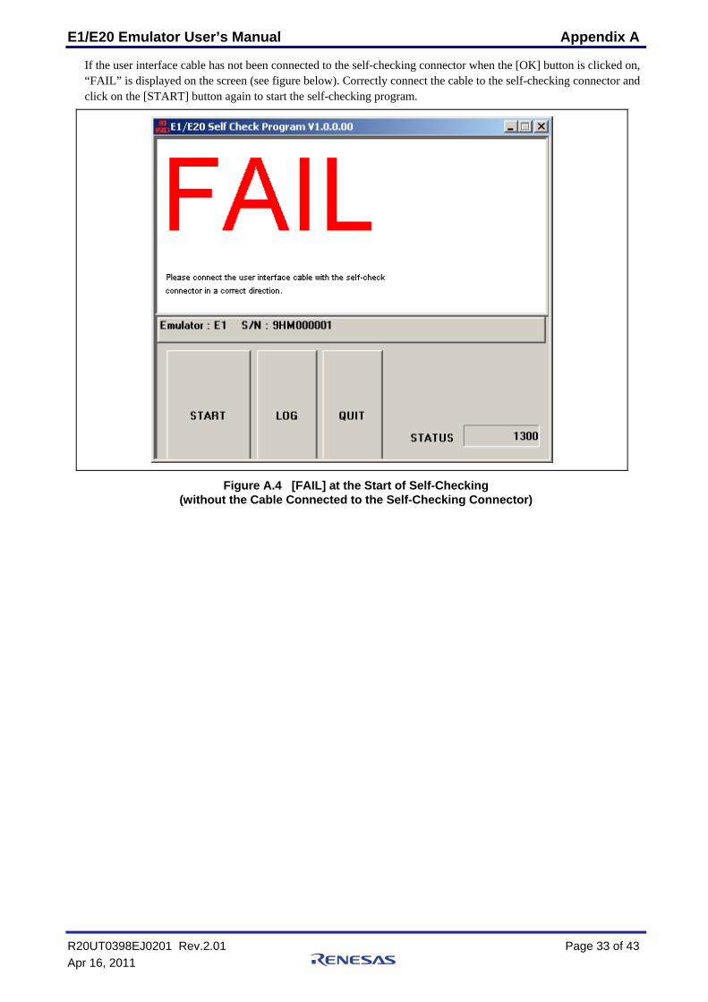
If the user interface cable has not been connected to the self-checking connector when the [OK] button is clicked on, “FAIL” is displayed on the screen (see figure below). Correctly connect the cable to the self-checking connector and click on the [START] button again to start the self-checking program.
Figure A.4 [FAIL] at the Start of Self-Checking (without the Cable Connected to the Self-Checking Connector)
R20UT0398EJ0201 Rev.2.01 Page 33 of 43 Apr 16, 2011
E1/E20 Emulator User’s Manual Appendix A
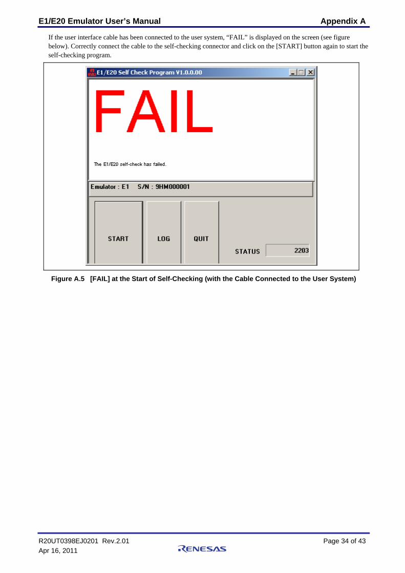
If the user interface cable has been connected to the user system, “FAIL” is displayed on the screen (see figure below). Correctly connect the cable to the self-checking connector and click on the [START] button again to start the self-checking program.
Figure A.5 [FAIL] at the Start of Self-Checking (with the Cable Connected to the User System)
R20UT0398EJ0201 Rev.2.01 Page 34 of 43 Apr 16, 2011
E1/E20 Emulator User’s Manual Appendix A
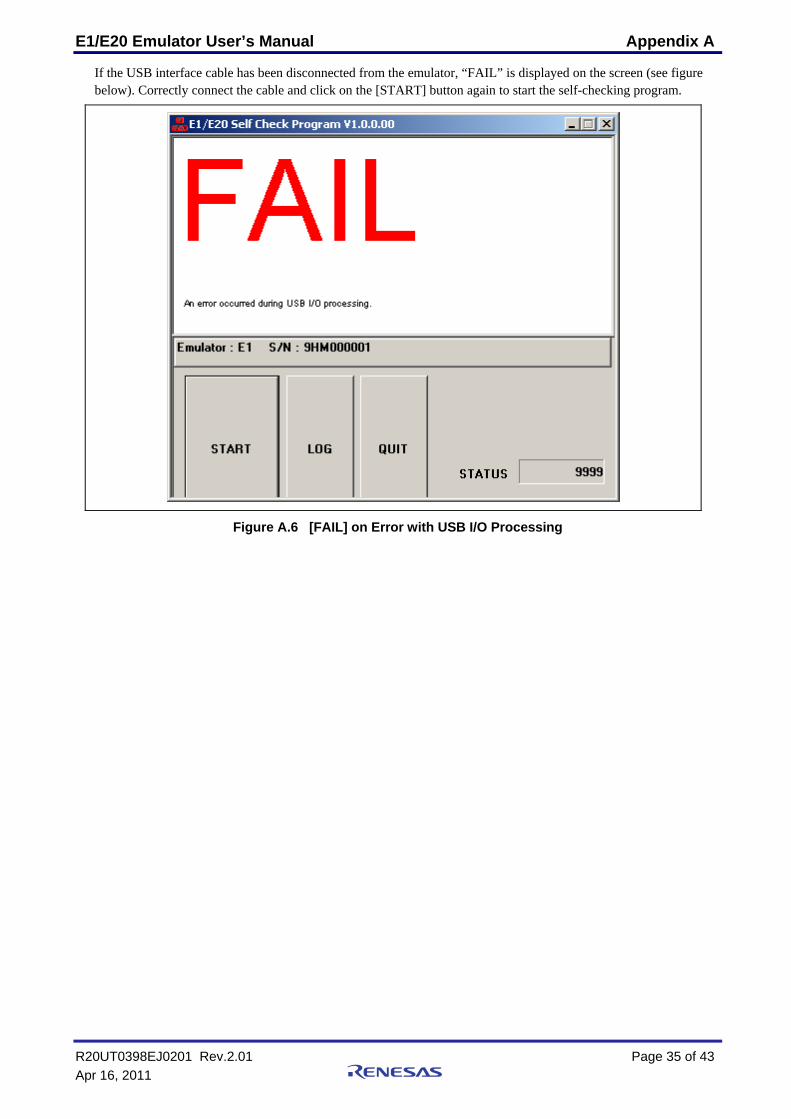
If the USB interface cable has been disconnected from the emulator, “FAIL” is displayed on the screen (see figure below). Correctly connect the cable and click on the [START] button again to start the self-checking program.
Figure A.6 [FAIL] on Error with USB I/O Processing
R20UT0398EJ0201 Rev.2.01 Page 35 of 43 Apr 16, 2011
E1/E20 Emulator User’s Manual Appendix A
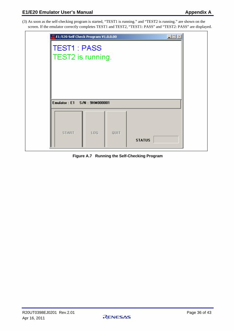
(3) As soon as the self-checking program is started, “TEST1 is running.” and “TEST2 is running.” are shown on the screen. If the emulator correctly completes TEST1 and TEST2, “TEST1: PASS” and “TEST2: PASS” are displayed.
Figure A.7 Running the Self-Checking Program
R20UT0398EJ0201 Rev.2.01 Page 36 of 43 Apr 16, 2011
E1/E20 Emulator User’s Manual Appendix A
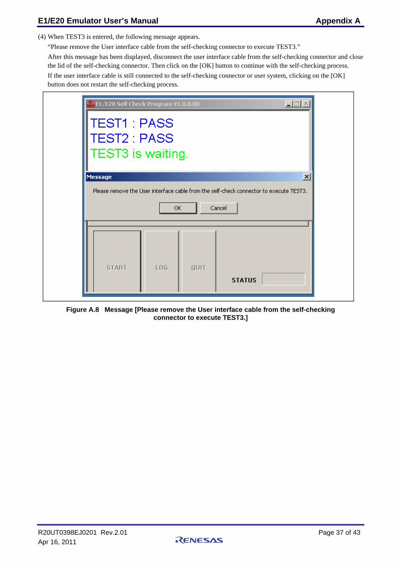
(4) When TEST3 is entered, the following message appears. “Please remove the User interface cable from the self-checking connector to execute TEST3.” After this message has been displayed, disconnect the user interface cable from the self-checking connector and close the lid of the self-checking connector. Then click on the [OK] button to continue with the self-checking process. If the user interface cable is still connected to the self-checking connector or user system, clicking on the [OK] button does not restart the self-checking process.
Figure A.8 Message [Please remove the User interface cable from the self-checking connector to execute TEST3.]
R20UT0398EJ0201 Rev.2.01 Page 37 of 43 Apr 16, 2011
E1/E20 Emulator User’s Manual Appendix A
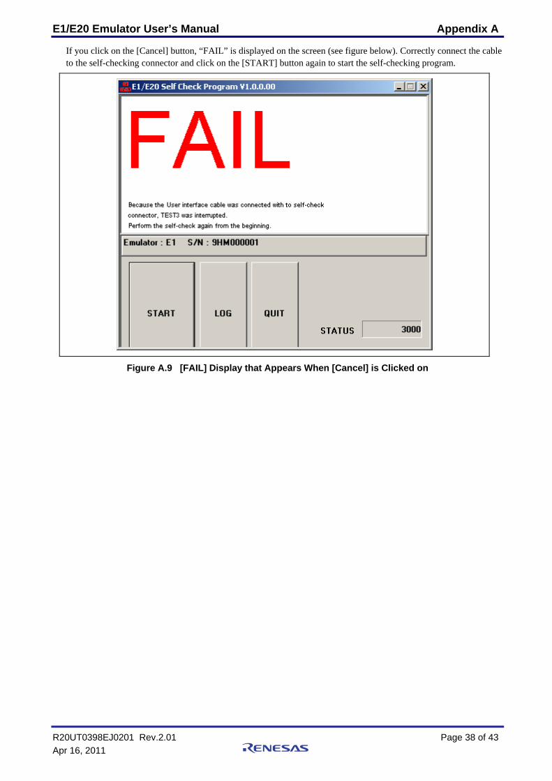
If you click on the [Cancel] button, “FAIL” is displayed on the screen (see figure below). Correctly connect the cable to the self-checking connector and click on the [START] button again to start the self-checking program.
Figure A.9 [FAIL] Display that Appears When [Cancel] is Clicked on
R20UT0398EJ0201 Rev.2.01 Page 38 of 43 Apr 16, 2011
E1/E20 Emulator User’s Manual Appendix A
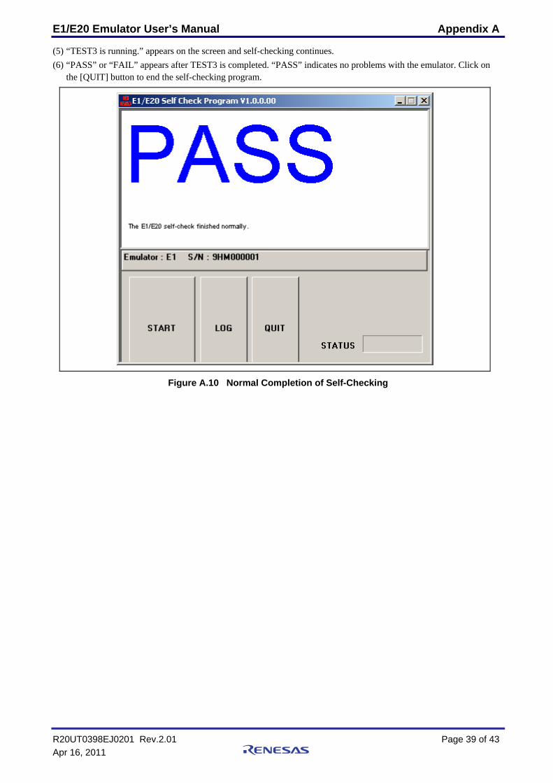
(5) “TEST3 is running.” appears on the screen and self-checking continues. (6) “PASS” or “FAIL” appears after TEST3 is completed. “PASS” indicates no problems with the emulator. Click on
the [QUIT] button to end the self-checking program.
Figure A.10 Normal Completion of Self-Checking
R20UT0398EJ0201 Rev.2.01 Page 39 of 43 Apr 16, 2011
E1/E20 Emulator User’s Manual Appendix A
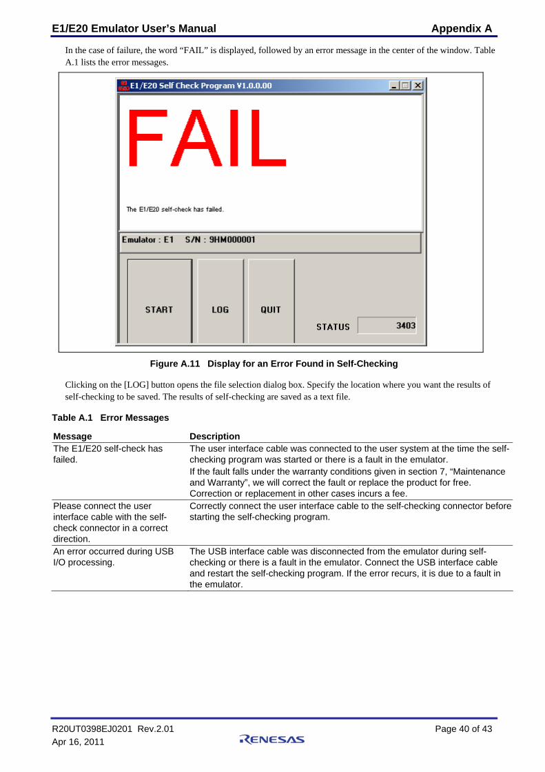
In the case of failure, the word “FAIL” is displayed, followed by an error message in the center of the window. Table A.1 lists the error messages.
Figure A.11 Display for an Error Found in Self-Checking
Clicking on the [LOG] button opens the file selection dialog box. Specify the location where you want the results of self-checking to be saved. The results of self-checking are saved as a text file.
Table A.1 Error Messages
Message Description The E1/E20 self-check has failed.
The user interface cable was connected to the user system at the time the self-checking program was started or there is a fault in the emulator. If the fault falls under the warranty conditions given in section 7, “Maintenance and Warranty”, we will correct the fault or replace the product for free. Correction or replacement in other cases incurs a fee.
Please connect the user interface cable with the self-check connector in a correct direction.
Correctly connect the user interface cable to the self-checking connector before starting the self-checking program.
An error occurred during USB I/O processing.
The USB interface cable was disconnected from the emulator during self-checking or there is a fault in the emulator. Connect the USB interface cable and restart the self-checking program. If the error recurs, it is due to a fault in the emulator.
R20UT0398EJ0201 Rev.2.01 Page 40 of 43 Apr 16, 2011
E1 Emulator R0E000010KCE00 E20 Emulator R0E000200KCT00 User’s Manual Publication Date: Jan 14, 2010 Rev.1.00
Apr 16, 2011 Rev.2.01
Published by: Renesas Electronics Corporation Edited by: Renesas Solutions Corp.
http://www.renesas.comRefer to "http://www.renesas.com/" for the latest and detailed information.
Renesas Electronics America Inc.2880 Scott Boulevard Santa Clara, CA 95050-2554, U.S.A.Tel: +1-408-588-6000, Fax: +1-408-588-6130Renesas Electronics Canada Limited1101 Nicholson Road, Newmarket, Ontario L3Y 9C3, CanadaTel: +1-905-898-5441, Fax: +1-905-898-3220Renesas Electronics Europe LimitedDukes Meadow, Millboard Road, Bourne End, Buckinghamshire, SL8 5FH, U.KTel: +44-1628-585-100, Fax: +44-1628-585-900Renesas Electronics Europe GmbHArcadiastrasse 10, 40472 Düsseldorf, Germany Tel: +49-211-65030, Fax: +49-211-6503-1327Renesas Electronics (China) Co., Ltd.7th Floor, Quantum Plaza, No.27 ZhiChunLu Haidian District, Beijing 100083, P.R.ChinaTel: +86-10-8235-1155, Fax: +86-10-8235-7679Renesas Electronics (Shanghai) Co., Ltd.Unit 204, 205, AZIA Center, No.1233 Lujiazui Ring Rd., Pudong District, Shanghai 200120, China Tel: +86-21-5877-1818, Fax: +86-21-6887-7858 / -7898Renesas Electronics Hong Kong LimitedUnit 1601-1613, 16/F., Tower 2, Grand Century Place, 193 Prince Edward Road West, Mongkok, Kowloon, Hong KongTel: +852-2886-9318, Fax: +852 2886-9022/9044Renesas Electronics Taiwan Co., Ltd.7F, No. 363 Fu Shing North Road Taipei, TaiwanTel: +886-2-8175-9600, Fax: +886 2-8175-9670Renesas Electronics Singapore Pte. Ltd.1 harbourFront Avenue, #06-10, keppel Bay Tower, Singapore 098632Tel: +65-6213-0200, Fax: +65-6278-8001Renesas Electronics Malaysia Sdn.Bhd.Unit 906, Block B, Menara Amcorp, Amcorp Trade Centre, No. 18, Jln Persiaran Barat, 46050 Petaling Jaya, Selangor Darul Ehsan, MalaysiaTel: +60-3-7955-9390, Fax: +60-3-7955-9510Renesas Electronics Korea Co., Ltd.11F., Samik Lavied' or Bldg., 720-2 Yeoksam-Dong, Kangnam-Ku, Seoul 135-080, KoreaTel: +82-2-558-3737, Fax: +82-2-558-5141
SALES OFFICES
© 2010-2011 Renesas Electronics Corporation and Renesas Solutions Corp. All rights reserved.Colophon 1.0
E1 Emulator R0E000010KCE00E20 Emulator R0E000200KCT00
User’s Manual
R20UT0398EJ0201