Embed Size (px)
Citation preview
iC-MU150 EVAL MU1MEVALUATION KIT DESCRIPTION
Rev A1, Page 1/9
ORDERING INFORMATION
Type Order Designation Description Options
Evaluation Kit iC-MU150 EVAL MU1M Evaluation kit with PCB, kit includes board MU1Mequipped with iC-MU150 DFN16-5x5 (pole pitch1.5mm) and an EEPROM;There are no magnetic discs included!
Suitable magnetic targets (rotary or linear) should be ordered from a third party (magnetic vendor). For moreinformation please contact the technical support of iC-Haus ([email protected]).
As an alternative solution a complete evaluation kit including magnetic targets is available for sensor chip iC-MU(pole pitch 1.28) which has nearly the same functionality with the exception of the pole pitch.http://www.ichaus.de/iC-MU
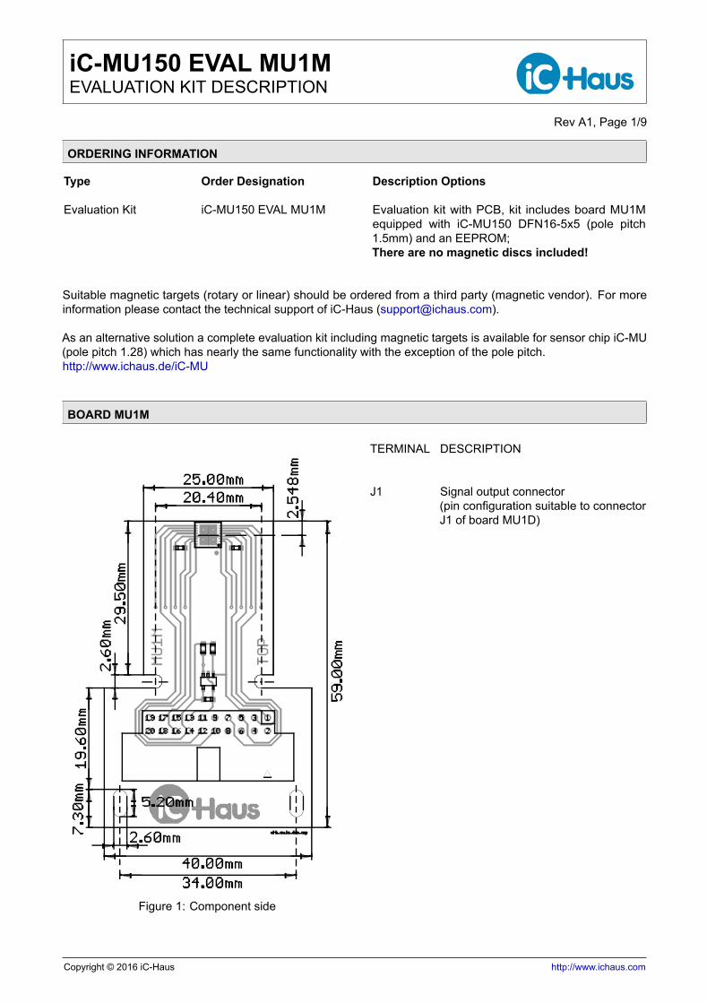
BOARD MU1M
Figure 1: Component side
TERMINAL DESCRIPTION
J1 Signal output connector(pin configuration suitable to connectorJ1 of board MU1D)
Copyright © 2016 iC-Haus http://www.ichaus.com
iC-MU150 EVAL MU1MEVALUATION KIT DESCRIPTION
Rev A1, Page 2/9
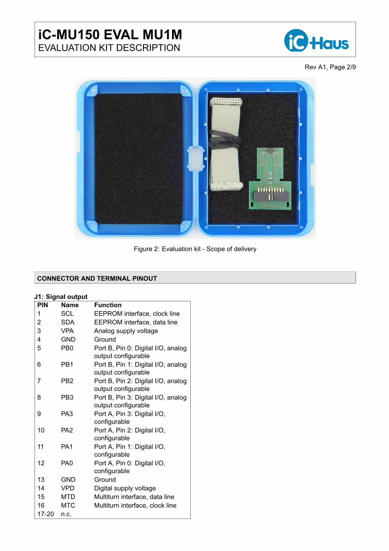
Figure 2: Evaluation kit - Scope of delivery
CONNECTOR AND TERMINAL PINOUT
J1: Signal outputPIN Name Function1 SCL EEPROM interface, clock line2 SDA EEPROM interface, data line3 VPA Analog supply voltage4 GND Ground5 PB0 Port B, Pin 0: Digital I/O, analog
output configurable6 PB1 Port B, Pin 1: Digital I/O, analog
output configurable7 PB2 Port B, Pin 2: Digital I/O, analog
output configurable8 PB3 Port B, Pin 3: Digital I/O, analog
output configurable9 PA3 Port A, Pin 3: Digital I/O,
configurable10 PA2 Port A, Pin 2: Digital I/O,
configurable11 PA1 Port A, Pin 1: Digital I/O,
configurable12 PA0 Port A, Pin 0: Digital I/O,
configurable13 GND Ground14 VPD Digital supply voltage15 MTD Multiturn interface, data line16 MTC Multiturn interface, clock line17-20 n.c.
iC-MU150 EVAL MU1MEVALUATION KIT DESCRIPTION
Rev A1, Page 3/9
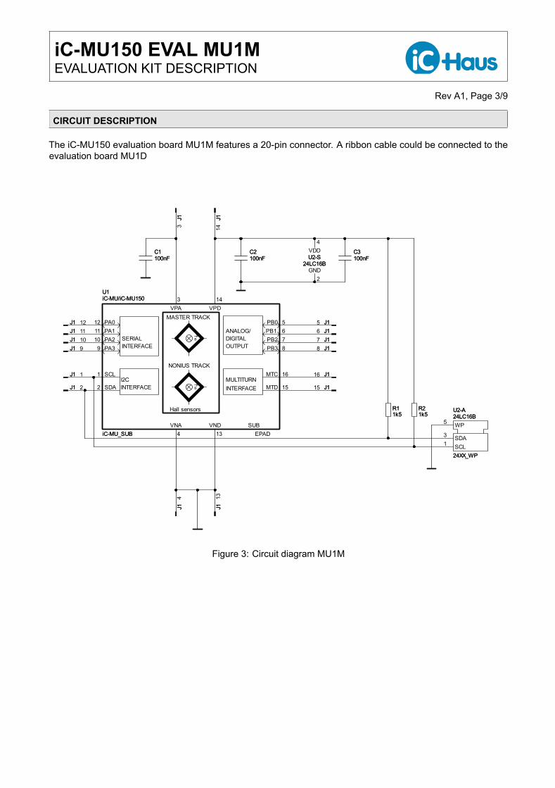
CIRCUIT DESCRIPTION
The iC-MU150 evaluation board MU1M features a 20-pin connector. A ribbon cable could be connected to theevaluation board MU1D
C3100nF
R11k5
24XX_WPSCL1SDA3
5 WP
U2-S24LC16B
2GND
4VDDC2
100nF
24LC16BU2-A
15
J116
100nFC1
J1 12
J113
J114
J1
8J1 9J1 10J1 11
J15J16J17J1
1
J1 2
J13
J14
6PB17PB28PB3
SCL1
SDA2
SUBEPAD
VNA4 13
VND
VPA3 14
VPD
J1
U1
iC-MU_SUB
iC-MU/iC-MU150
MTC 16
15MTD
12 PA0PA111PA210PA39
PB0 5
1k5R2R21k5
MULTITURNINTERFACE
I2CINTERFACE
ANALOG/DIGITALOUTPUT
SERIAL
NONIUS TRACK
MASTER TRACK
B
Hall sensors
B
INTERFACE
iC-MU/iC-MU150
iC-MU_SUB
U1
J1
J1
J1J1
J1J1J1J1J1
J1J1J1
J1J1
J1
J1
C1100nF 100nF
C2
24XX_WP
U2-A24LC16B
24LC16BU2-S 100nF
C3
1k5R1
Figure 3: Circuit diagram MU1M
iC-MU150 EVAL MU1MEVALUATION KIT DESCRIPTION
Rev A1, Page 4/9
ASSEMBLY PART LISTS
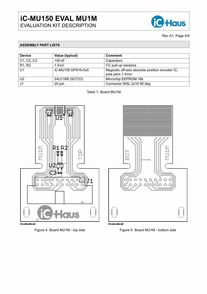
Device Value (typical) CommentC1, C2, C3 100 nF CapacitorsR1, R2 1.5 kΩ I2C pull-up resistorsU1 iC-MU150 DFN16-5x5 Magnetic off-axis absolute position encoder IC,
pole pitch 1.5mmU2 24LC16B (SOT23) Microchip EEPROM 16kJ1 20 pol. Connector WSL 2x10 90 deg
Table 1: Board MU1M
Figure 4: Board MU1M - top side Figure 5: Board MU1M - bottom side
iC-MU150 EVAL MU1MEVALUATION KIT DESCRIPTION
Rev A1, Page 5/9
APPLICATION EXAMPLE
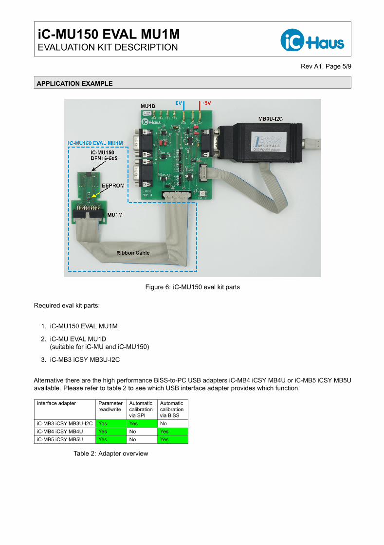
Figure 6: iC-MU150 eval kit parts
Required eval kit parts:
1. iC-MU150 EVAL MU1M
2. iC-MU EVAL MU1D(suitable for iC-MU and iC-MU150)
3. iC-MB3 iCSY MB3U-I2C
Alternative there are the high performance BiSS-to-PC USB adapters iC-MB4 iCSY MB4U or iC-MB5 iCSY MB5Uavailable. Please refer to table 2 to see which USB interface adapter provides which function.
Interface adapter Parameterread/write
Automaticcalibrationvia SPI
Automaticcalibrationvia BiSS
iC-MB3 iCSY MB3U-I2C Yes Yes NoiC-MB4 iCSY MB4U Yes No YesiC-MB5 iCSY MB5U Yes No Yes
Table 2: Adapter overview
iC-MU150 EVAL MU1MEVALUATION KIT DESCRIPTION
Rev A1, Page 6/9
EVAL BOARD CONFIGURATION
The MU1M eval board is configured with a default configuration. In this configuration the SPI interface is selected.The eval kit MU1M + MU1D can be used with the interface adapter MB3U-I2C. Furthermore a axial magnetizedmagnetic target with 32/31 pole pairs can be used with the default configuration. Before the system is workingcorrect, a calibration procedure is required. Please refer to the corresponding documents and app notes listed onthe product web page of iC-MU150 http://www.ichaus.de/product/iC-MU150
Switch MU1M to BiSS InterfaceIn case the interface adapter MB4U or MB5U should used for programming and calibration, the eval board MU1Mmust be set to BiSS interface mode. If there is no MB3U-I2C adapter available, please do the following steps.
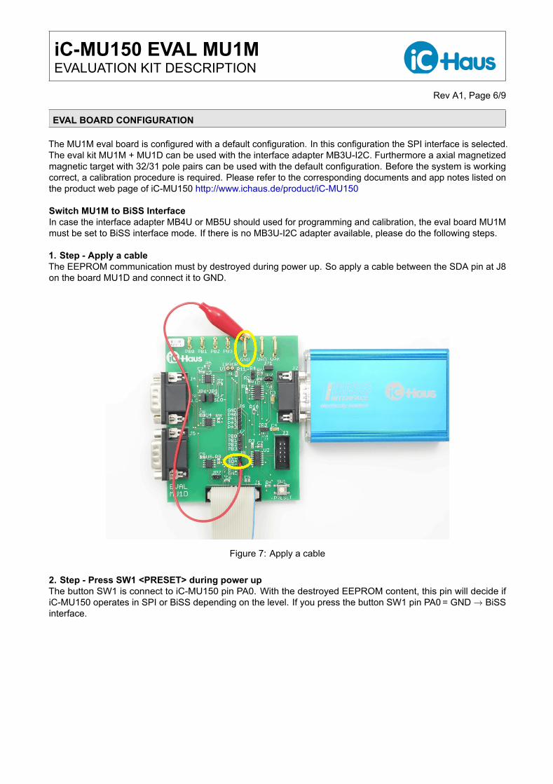
1. Step - Apply a cableThe EEPROM communication must by destroyed during power up. So apply a cable between the SDA pin at J8on the board MU1D and connect it to GND.
Figure 7: Apply a cable
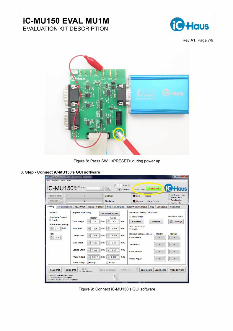
2. Step - Press SW1 <PRESET> during power upThe button SW1 is connect to iC-MU150 pin PA0. With the destroyed EEPROM content, this pin will decide ifiC-MU150 operates in SPI or BiSS depending on the level. If you press the button SW1 pin PA0 = GND → BiSSinterface.
iC-MU150 EVAL MU1MEVALUATION KIT DESCRIPTION
Rev A1, Page 7/9
Figure 8: Press SW1 <PRESET> during power up
3. Step - Connect iC-MU150’s GUI software
Figure 9: Connect iC-MU150’s GUI software
iC-MU150 EVAL MU1MEVALUATION KIT DESCRIPTION
Rev A1, Page 8/9
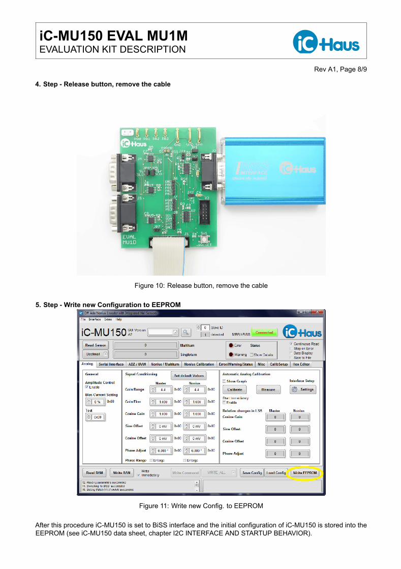
4. Step - Release button, remove the cable
Figure 10: Release button, remove the cable
5. Step - Write new Configuration to EEPROM
Figure 11: Write new Config. to EEPROM
After this procedure iC-MU150 is set to BiSS interface and the initial configuration of iC-MU150 is stored into theEEPROM (see iC-MU150 data sheet, chapter I2C INTERFACE AND STARTUP BEHAVIOR).
iC-MU150 EVAL MU1MEVALUATION KIT DESCRIPTION
Rev A1, Page 9/9
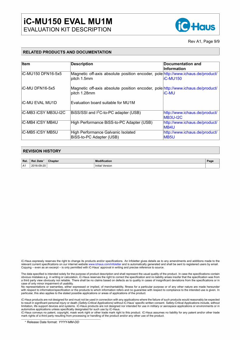
RELATED PRODUCTS AND DOCUMENTATION
Item Description Documentation andInformation
iC-MU150 DFN16-5x5 Magnetic off-axis absolute position encoder, polepitch 1.5mm
http://www.ichaus.de/product/iC-MU150
iC-MU DFN16-5x5 Magnetic off-axis absolute position encoder, polepitch 1.28mm
http://www.ichaus.de/product/iC-MU
iC-MU EVAL MU1D Evaluation board suitable for MU1M
iC-MB3 iCSY MB3U-I2C BiSS/SSI and I2C-to-PC adapter (USB) http://www.ichaus.de/product/MB3U-I2C
iC-MB4 iCSY MB4U High Performance BiSS-to-PC Adapter (USB) http://www.ichaus.de/product/MB4U
iC-MB5 iCSY MB5U High Performance Galvanic IsolatedBiSS-to-PC Adapter (USB)
http://www.ichaus.de/product/MB5U
REVISION HISTORY
Rel. Rel. Date∗ Chapter Modification PageA1 2016-09-20 Initial Version
iC-Haus expressly reserves the right to change its products and/or specifications. An Infoletter gives details as to any amendments and additions made to therelevant current specifications on our internet website www.ichaus.com/infoletter and is automatically generated and shall be sent to registered users by email.Copying – even as an excerpt – is only permitted with iC-Haus’ approval in writing and precise reference to source.
The data specified is intended solely for the purpose of product description and shall represent the usual quality of the product. In case the specifications containobvious mistakes e.g. in writing or calculation, iC-Haus reserves the right to correct the specification and no liability arises insofar that the specification was froma third party view obviously not reliable. There shall be no claims based on defects as to quality in cases of insignificant deviations from the specifications or incase of only minor impairment of usability.No representations or warranties, either expressed or implied, of merchantability, fitness for a particular purpose or of any other nature are made hereunderwith respect to information/specification or the products to which information refers and no guarantee with respect to compliance to the intended use is given. Inparticular, this also applies to the stated possible applications or areas of applications of the product.
iC-Haus products are not designed for and must not be used in connection with any applications where the failure of such products would reasonably be expectedto result in significant personal injury or death (Safety-Critical Applications) without iC-Haus’ specific written consent. Safety-Critical Applications include, withoutlimitation, life support devices and systems. iC-Haus products are not designed nor intended for use in military or aerospace applications or environments or inautomotive applications unless specifically designated for such use by iC-Haus.iC-Haus conveys no patent, copyright, mask work right or other trade mark right to this product. iC-Haus assumes no liability for any patent and/or other trademark rights of a third party resulting from processing or handling of the product and/or any other use of the product.
∗ Release Date format: YYYY-MM-DD