Embed Size (px)
Citation preview
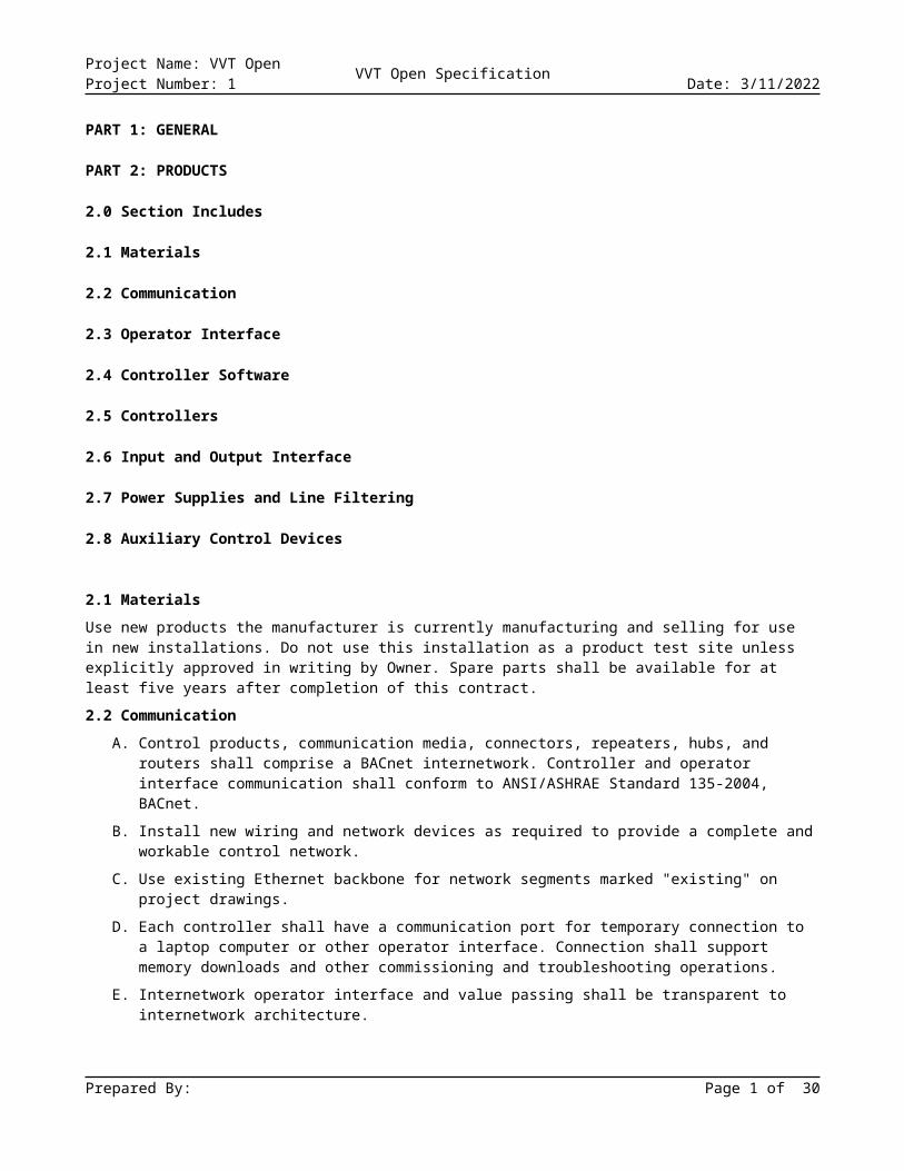
Project Name: VVT Open VVT Open SpecificationProject Number: 1 Date: 5/14/2023
PART 1: GENERAL
PART 2: PRODUCTS
2.0 Section Includes
2.1 Materials
2.2 Communication
2.3 Operator Interface
2.4 Controller Software
2.5 Controllers
2.6 Input and Output Interface
2.7 Power Supplies and Line Filtering
2.8 Auxiliary Control Devices
2.1 Materials Use new products the manufacturer is currently manufacturing and selling for use in new installations. Do not use this installation as a product test site unless explicitly approved in writing by Owner. Spare parts shall be available for at least five years after completion of this contract.
2.2 Communication A. Control products, communication media, connectors, repeaters, hubs, and routers shall comprise a
BACnet internetwork. Controller and operator interface communication shall conform to ANSI/ASHRAE Standard 135-2004, BACnet.
B. Install new wiring and network devices as required to provide a complete and workable control network.
C. Use existing Ethernet backbone for network segments marked "existing" on project drawings.
D. Each controller shall have a communication port for temporary connection to a laptop computer or other operator interface. Connection shall support memory downloads and other commissioning and troubleshooting operations.
E. Internetwork operator interface and value passing shall be transparent to internetwork architecture.
1. An operator interface connected to a controller shall allow the operator to interface with each internetwork controller as if directly connected. Controller information such as data, and status shall be viewable and editable from each internetwork controller.
2. Inputs, outputs, and control variables used to integrate control strategies across multiple controllers shall be readable by each controller on the internetwork. An authorized operator shall be able to edit cross-controller links by typing a standard object address or by using a point-and-click interface.
F. Controllers with real-time clocks shall use the BACnet Time Synchronization service. System shall automatically synchronize system clocks daily from an operator-designated controller via the internetwork. If applicable, system shall automatically adjust for daylight saving and standard time.
2.3 Operator Interface
Prepared By: Page 1 of 21
Project Name: VVT Open VVT Open SpecificationProject Number: 1 Date: 5/14/2023
A. Description. The control system shall be as shown and consist of a high-speed, peer-to-peer network of DDC controllers and a stand alone web server operator interface. Depict each mechanical system and building floor plan by a point-and-click graphic. A web server shall gather data from this system and generate web pages accessible through a conventional web browser on each PC connected to the network. Operators shall be able to perform all normal operator functions through the web browser interface. Operators with sufficient access level shall have an ability to make changes to all system and equipment graphics in the web server in addition to having full DDC system access to make configuration changes to the control system. Any tools required for making graphic changes shall be provided with web server.
B. Operator Interface. Furnish one Web server interface as shown on the system drawings. Operators shall be able to access all necessary operational information in the DDC system via client computer utilizing IE web browser. Client computer and IE web browsing software shall not be furnished under this section.
1. Web server shall connect via the LAN and be able to simultaneously serve up controller information to multiple operators connected via LAN with IE web browsers. Each client web browser connected to server shall be able to access all system information.
2. Web server shall be compatible with Wireless Access Protocol (WAP) enabled cellular telephone or personal digital assistant (PDA). The PDA/WAP interface may be text-based and shall provide a summary of the most important data.
3. With the use of a remote SMTP email server the operators interface web server shall be able to notify personnel of an alarm or record information about an alarm in the DDC system.
C. Web Server Hardware. Furnish one compact web server with Ethernet port for LAN or direct operator client computer access. The web server shall be capable of communicating to the peer to peer DDC controller network. Any required installation or commissioning software shall be pre-installed on the web server. Installation or commissioning of the web server shall be done through a client computer with a standard web browser.
D. Communication. Web server or workstation and controllers shall communicate using BACnet protocol. Web server or workstation and control network backbone shall communicate using ISO 8802-3 (Ethernet) Data Link/Physical layer protocol and BACnet/IP addressing as specified in ANSI/ASHRAE 135-2004, BACnet Annex J.
E. Operator Functions. Operator interface shall allow each authorized operator to execute the following functions as a minimum:
1. Log In and Log Out. System shall require user name and password to log in to operator interface.
2. Point-and-click Navigation. Operator interface shall be graphically based and shall allow operators to access graphics for equipment and geographic areas using point-and-click navigation.
3. View and Adjust Equipment Properties. Operators shall be able to view controlled equipment status and to adjust operating parameters such as set points, PID gains, on and off controls, and sensor calibration.
4. View and Adjust Operating Schedules. Operators shall be able to view scheduled operating hours of each schedulable piece of equipment on a weekly or monthly calendar-based graphical schedule display, to select and adjust each schedule and time period, and to simultaneously schedule related equipment. System shall clearly show exception schedules and holidays on the schedule display.
5. View and Respond to Alarms. Operators shall be able to view a list of currently active system alarms, to acknowledge each alarm, and to clear (delete) unneeded alarms. Remote users shall be able to receive alarms via emails or cell phone text messages.
6. View and Configure Trends. Operators shall be able to view a trend graph of each trended point and to edit graph configuration to display a specific time period or data range. Operator shall be
Prepared By: Page 2 of 21
Project Name: VVT Open VVT Open SpecificationProject Number: 1 Date: 5/14/2023
able to create custom trend graphs to display on the same page data from multiple trended points.
7. View and Configure Reports. Operators shall be able to run preconfigured reports, to view report results, and to customize report configuration to show data of interest.
8. Manage Control System Hardware. Operators shall be able to view controller status, to restart (reboot) each controller, and to download new control software to each controller.
9. Manage Operator Access. Typically, only a few operators are authorized to manage operator access. Authorized operators shall be able to view a list of operators with system access and of functions they can perform while logged in. Operators shall be able to add operators, to delete operators, and to edit operator function authorization. Operator shall be able to authorize each operator function separately.
B. System Software.
1. Operating System and required software. Web server operator interface shall be a self contained web server without the need for any type of maintenance. Any required operating system or software shall be factory loaded and maintenance free.
2. System Graphics. Operator interface shall be graphical and shall include at least one graphic per piece of equipment or occupied zone, graphics for each chilled water and hot water system, and graphics that summarize conditions on each floor of each building included in this contract. Indicate thermal comfort on floor plan summary graphics using dynamic colors to represent zone temperature relative to zone setpoint.
a. Functionality. Graphics shall allow operator to monitor system status, to view a summary of the most important data for each controlled zone or piece of equipment, to use point-and-click navigation between zones or equipment, and to edit setpoints and other specified parameters.
b. Animation. Graphics shall be able to animate by displaying different image files for changed object status.
c. Alarm Indication. Indicate areas or equipment in an alarm condition using color or other visual indicator.
d. Format. Graphics shall be saved in an industry-standard format such as BMP, JPEG, PNG, or GIF. Web-based system graphics shall be viewable on browsers compatible with World Wide Web Consortium browser standards. Web graphic format shall require no plug-in (such as HTML and JavaScript) or shall only require widely available no-cost plug-ins (such as Active-X and Macromedia Flash).
C. System Tools. System shall provide the following functionality to authorized operators as an integral part of the operator interface or as stand-alone software programs. If furnished as part of the interface, the tool shall be available from each workstation or web browser interface. If furnished as a stand-alone program, software shall be installable on standard Windows compatible PCs with no limit on the number of copies that can be installed under the system license.
1. Automatic System Database Configuration. Each web server shall store internally store a copy of the current system database, including controller firmware and software. Stored database shall be automatically updated with each system configuration or controller firmware or software change.
2. Controller Memory Download. Operators shall be able to download memory from the system database to each controller.
3. System Configuration. Operators shall be able to configure the system.
4. Online Help. Context-sensitive online help for each tool shall assist operators in operating and editing the system.
5. Security. System shall require a user name and password to view, edit, add, or delete data.
Prepared By: Page 3 of 21
Project Name: VVT Open VVT Open SpecificationProject Number: 1 Date: 5/14/2023
a. Operator Access. Each user name and password combination shall define accessible viewing, editing, adding, and deleting functions in each system application, editor, and object.
b. Automatic Log Out. Automatically log out each operator if no keyboard or mouse activity is detected. Operators shall be able to adjust automatic log out delay.
c. Encrypted Security Data. Store system security data including operator passwords in an encrypted format. System shall not display operator passwords.
6. System Diagnostics. System shall automatically monitor controller and I/O point operation. System shall annunciate controller failure and I/O point locking (manual overriding to a fixed value).
7. Alarm Processing. System input and status objects shall be configurable to alarm on departing from and on returning to normal state. Operator shall be able to enable or disable each alarm and to configure alarm limits, alarm limit differentials, alarm states, and alarm reactions for each system object. Configure and enable alarm points as specified in Points List. Alarms shall be BACnet alarm objects and shall use BACnet alarm services.
8. Alarm Messages. Alarm messages shall use an English language descriptor without acronyms or mnemonics to describe alarm source, location, and nature.
9. Alarm Reactions. Operator shall be able to configure (by object) actions workstation or web server shall initiate on receipt of each alarm. As a minimum, workstation or web server shall be able to log, print, start programs, display messages, send e-mail, send page, and audibly annunciate.
10. Alarm Maintenance. Operators shall be able to view system alarms and changes of state chronologically, to acknowledge and delete alarms, and to archive closed alarms to the workstation or web server from each workstation or web browser interface.
11. Trend Configuration. Operator shall be able to configure trend sample or change of value (COV) interval, start time, and stop time for each system data object and shall be able to retrieve data for use in spreadsheets and standard database programs. Controller shall sample and store trend data and shall be able to archive data to the hard disk. Configure trends as specified in Points List. Trends shall be BACnet trend objects.
12. Object and Property Status and Control. Operator shall be able to view, and to edit if applicable, the status of each system object and property by menu, on graphics.
13. Reports and Logs. Operator shall be able to select, to modify, to create, and to print reports and logs. Operator shall be able to store report data in a format accessible by standard spreadsheet and word processing programs.
14. Standard Reports. Furnish the following standard system reports:
a. Reports shall be filtered based upon the selected equipment
b. Alarm Reports
i. Alarm Summary - Current alarms
ii. Alarm Sources – List of equipment and associated alarm conditions
iii. Alarm Actions – Configured alarm actions such as e-mail and alarm pop-up
c. Schedule Reports
i. Effective Schedules – Displays effective schedules for each equipment
ii. Schedule Instances – Displays all schedules entered
d. Security Reports – Maintains audit of all actions taken through user interface
e. Commissioning Reports – Provide equipment checkout status and notes
Prepared By: Page 4 of 21
Project Name: VVT Open VVT Open SpecificationProject Number: 1 Date: 5/14/2023
f. Equipment Reports – Provide reports showing trended points and available network points
15. Custom Reports. Operator shall be able to create custom reports that retrieve data, including archived trend data, from the system, that analyze data using common algebraic calculations, and that present results in tabular or graphical format. Reports shall be launched from the operator interface.
16. Graphics Generation. Graphically based tools and documentation shall allow Operator to edit system graphics, to create graphics, and to integrate graphics into the system. Operator shall be able to add analog and binary values, dynamic text, static text, and animation files to a background graphic using a mouse.
17. Graphics Library. Complete library of standard HVAC equipment graphics shall include equipment such as chillers, boilers, air handlers, terminals, fan coils, and unit ventilators. Library shall include standard symbols for other equipment including fans, pumps, coils, valves, piping, dampers, and ductwork. Library graphic file format shall be compatible with graphics generation tools.
D. Portable Operator's Terminal. Provide all necessary software to configure an IBM-compatible laptop computer for use as a Portable Operator's Terminal. Operator shall be able to connect configured Terminal to the system network or directly to each controller for programming, setting up, and troubleshooting.
E. Timed override reporting (i-Vu Plus only)
1. The DDC system shall track all push button timed override events during unoccupied periods. The system shall store time of the override event and time duration for each override event.
2. Web server shall allow operators to create custom reports detailing timed override events. Timed override reports shall allow the following options:
3. Minimum billing time. A minimum amount of time that each override event will last.
4. Billing rate. A monetary rate per hour or per minute of the override duration.
5. Exemption times. A defined block of time during each week that is exempt from detecting override events.
6. Allowances. A dollar amount of override usage that is allowed per tenant and is given at no charge. This allowance will be subtracted from the tenant’s total override usage.
F. Web services data exchange (i-Vu Plus only) System shall support Web services data exchange with any other system that complies with XML (extensible markup language) and SOAP (simple object access protocol) standards specified by the Web Services Interoperability Organization (WS-I) Basic Profile 1.0 or higher. Web services support shall as a minimum be provided at the workstation or web server level and shall enable data to be read from or written to the DDC system.
1. System shall support Web services read data requests by retrieving requested trend data or point values (I/O hardware points, analog value software points, or binary value software points) from any system controller or from the trend history database.
2. System shall support Web services write data request to each analog and binary object that can be edited through the system operator interface by downloading a numeric value to the specified object.
3. For read or write requests, the system shall require user name and password authentication and shall support SSL (Secure Socket Layer) or equivalent data encryption.
4. System shall support discovery through a Web services connection or shall provide a tool available through the Operator Interface that will reveal the path/identifier needed to allow a third party Web services device to read data from or write data to any object in the system which supports this service.
Prepared By: Page 5 of 21
Project Name: VVT Open VVT Open SpecificationProject Number: 1 Date: 5/14/2023
2.4 Controller Software A. Building and energy management application software shall reside and operate in system controllers.
Applications shall be configurable through the operator workstation, web browser interface, or engineering workstation.
B. Memory and System Time. All controllers shall have a Non-Volatile Memory providing indefinite storage of application and configuration data. The system must have an ability to maintain time, and automatically correct for daylight savings time and leap year adjustments. In the event of power failure or user generated power cycle, all system components must automatically updated with current time and date from a network Time Sync device. The controller shall also have the capability of changing occupancy mode by reading a set of discrete, dry contacts controlled by an external time clock.
C. Stand alone capability. All controllers shall be capable of providing all control functions of the HVAC system without the use of a computer. The controllers shall include the inherent capability to access the system control selections as well as to monitor system performance by means of a communicating network with a PC and EMS software program.
D. System Security.
1. For Web server operator interface security options See Paragraph 2.3.G.5 (Security).
2. Other hand held or wall mounted local interface device that allow configuration access shall be password protected with minimum of two levels of security. Level one shall provide limited access to controller operational parameters and level two shall provide full access to controller operational and configuration parameters.
E. Scheduling. For Web server operator interface scheduling See Paragraph 2.3.E.4 (View and Adjust Operating Schedules).
1. System shall provide the following schedule options as a minimum:
2. Weekly. Provide separate schedules for each day of the week. Each schedule shall be able to include up to 5 occupied periods (5 start-stop pairs or 10 events).
3. Exception. Operator shall be able to designate an exception schedule for each of the next 365 days. After an exception schedule has executed, system shall discard and replace exception schedule with standard schedule for that day of the week.
4. Holiday. Operator shall be able to define 24 special or holiday schedules of varying length on a scheduling calendar that repeats each year.
F. Binary and Analog Alarms. See Paragraph 2.3.G.7 (Alarm Processing).
G. Alarm Reporting. See Paragraph 2.3.G.9 (Alarm Reactions).
H. Remote Communication. System shall automatically contact operator workstation or server on receipt of critical alarms.
I. Demand Limiting.
1. System shall monitor building power consumption from building power meter pulse generator signals or from building feeder line watt transducer or current transformer.
2. When power consumption exceeds adjustable levels, system shall automatically adjust set points, de-energize low-priority equipment, and take other programmatic actions to reduce demand as specified in Sequence of Operations for HVAC Controls. When demand drops below adjustable levels, system shall restore loads as specified.
3. The controller shall be capable of providing separate heating and cooling demand control utilizing two independent demand inputs.
J. Sequencing. Application software shall sequence chillers, boilers, and pumps as specified in Sequence of Operations for HVAC Controls.
K. PID Control. System shall provide direct- and reverse-acting PID (proportional-integral-derivative) algorithms. Each algorithm shall have anti-windup and selectable controlled variable, setpoint, and PID
Prepared By: Page 6 of 21
Project Name: VVT Open VVT Open SpecificationProject Number: 1 Date: 5/14/2023
gains. Each algorithm shall calculate a time-varying analog value that can be used to position an output or to stage a series of outputs.
L. Staggered Start. System shall stagger controlled equipment restart after power outage. Operator shall be able to adjust equipment restart order and time delay between equipment restarts.
M. Anti-Short Cycling. Binary output objects shall be protected from short cycling by means of preconfigured minimum on-time and off-time settings, customized for the specific requirements of the application.
N. On and Off Control with Differential. System shall provide direct- and reverse-acting on and off algorithms with adjustable differential to cycle a binary output based on a controlled variable and setpoint.
O. Zoning system compatible with constant volume air source (Variable Volume/Variable Temperature) (VVT). The zoning system shall be compatible with constant volume air source and consist of programmable, multiple communicating Zone Controllers and a Bypass Controller. The system shall also include a complete array of input and output devices. The system shall provide full control of HVAC heating and cooling equipment in a multiple zone application. The zoning system shall be capable of operating as a stand-alone system or networked with multiple systems to communicating air source controllers.
1. Zone control. Each zone shall be capable of monitoring space conditions and providing the correct amount of conditioned air to satisfy the space load. Each zone shall be capable of the following:
a. Space temperatures control. To maintain individual heating and cooling set points.
b. Relative Humidity/Air Quality (DCV). Each zone shall be capable of maintaining space relative humidity set point or air quality set point (zone level demand control ventilation) as defined in ASHRAE 62-1989 (including Addendum 62a-1990).
c. Demand coordination. Each zone shall be capable of zone demand data coordination with other zones in the system.
2. Static pressure control. The zoning system shall be capable of maintaining a user adjustable supply air duct static pressure set point.
a. The Bypass controller shall additionally provide the capability to increase system airflow during conditions when the temperature of the supply air from the equipment is approaching the limits of operation. In these cases, the Bypass controller shall raise the static pressure setpoint to a user configurable maximum limit in order to increase the system airflow during these conditions.
b. The Bypass control shall contain the ability to monitor the bypass damper movement (or VFD speed) and automatically adjust the setpoint control band and/or hysteresis in order to provide stability and prevent premature actuator failure.
3. Air source control. Shall control all associated HVAC rooftop equipment functions, and be capable of stand-alone or networked operation. The resident algorithms shall use error reduction logic as designated in ASHRAE standard 90.1 to provide temperature control and lower energy usage. The Air source shall be capable of zone demand data coordination with the associated zones.
4. System Terminal Modes. Each air terminal mode shall be based on the current air source mode, terminal type, space temperature, and the current temperature set points.
a. Off:
i. All terminal dampers will maintain a 65% open position. Fans shall be disabled.
ii. If the zone requirement is heating, all single duct terminals shall maintain their damper position at 65%. Any zone controller servicing a parallel box shall fully close their dampers while the fan is operating. If local heat is available, the parallel fans shall start and local heat shall be enabled to maintain its unoccupied
Prepared By: Page 7 of 21
Project Name: VVT Open VVT Open SpecificationProject Number: 1 Date: 5/14/2023
heating set point. The damper shall be modulated open to 65% after heating is no longer required.
b. Cooling and Night Time Free Cooling (NTFC):
i. If the zone requirement is none, then the zone controllers shall modulate their dampers to maintain their minimum cooling damper position or damper ventilation position if the supply air temp is between 65 and 75 F. During the NTFC mode the zone controller shall control between its occupied heating and cooling set points. During the cooling mode, the zone controller shall modulate its damper to its appropriate (occupied or unoccupied) cooling set point.
ii. If the zone requirement is cooling, then the zone controllers shall modulate their air dampers between their minimum and maximum cooling damper position to maintain their cooling set point. Parallel fans shall be disabled unless the damper has closed below the user adjustable fan-on minimum position (optional). In that case, the fan shall be energized to mix return air with the cold primary air in order to prevent “cold air dumping” from the diffusers.
iii. If the zone requirement is heating, then the zone controllers shall modulate their dampers to maintain their minimum cooling damper position. Any zone controllers servicing single duct units with reheat capability shall maintain the greater of either the minimum cooling damper position or the specified reheat damper position. Zone controllers servicing parallel units shall enable their fans while the damper shall maintain its minimum cooling damper position.
c. Vent:
i. If the air source equipment is operating in a fan only mode to provide ventilation without mechanical heating or cooling, then the zone controllers shall maintain the user configured ventilation damper position.
d. Heat:
i. If the zone requirement is none, then the zone controller shall maintain its minimum heating damper position. Parallel fans shall be disabled and their air damper shall be modulated to maintain their minimum heating damper position.
ii. If the zone requirement is cooling, then the zone controller shall modulate its damper to maintain its minimum heating damper position. Parallel fans shall be disabled.
iii. If the zone requirement is heating, then the zone controllers shall modulate their air dampers between their minimum and maximum heating damper position to maintain their heating set point.
e. Pressurization:
i. If the zone requirement is none or cooling, then the zone controller shall maintain its maximum cooling damper position. Parallel fans shall be disabled.
ii. If the zone requirement is heating, and the zone controller has been enabled to provide local heating, then the zone controller shall modulate its damper to its maximum cooling damper position and enable its auxiliary heat. If local heat is not available, the damper shall still be modulated to maintain its maximum cooling damper position.
f. Evacuation:
i. During the Evacuation mode all terminal fans shall be disabled and all dampers shall close.
5. Air source interface. The zoning system shall be capable of zone demand data coordination with a communicating rooftop. Setpoint and zone temperature information from the zones shall be shared with the rooftop controller so that the rooftop controller’s error reduction calculations
Prepared By: Page 8 of 21
Project Name: VVT Open VVT Open SpecificationProject Number: 1 Date: 5/14/2023
can determine the proper number of heating or cooling stages to operate in order to satisfy the system load.
a. The zoning system shall have the capability of linking up to 32 zones to a single air source and determining system heating and cooling requirements.
b. The zoning system shall be capable of providing a communication check of all associated controls and display device type as well as error conditions.
c. The zoning system shall coordinate and exchange the flowing data as minimum:
i. Average zone temperature
ii. Average occupied zone temperature
iii. Average occupied and unoccupied heat/cool set points
iv. Occupancy status
d. Space temperature and space temperature set points for use by the air source controller shall include a weighted factor, proportional to the size of the zone.
e. Only those zones with valid temperature readings shall be included.
f. The zoning system shall provide periodic updates to the air source.
g. The zoning system shall obtain and support the following air source modes as a minimum:
i. Off
ii. Cooling
iii. Heating
iv. Night Time Free Cooling
v. Ventilation
vi. Pressurization
vii. Evacuation
h. The air source controller shall, through the Air Distribution System, bias its occupancy time schedules to provide optimization routines and occupant override.
i. For those zoning systems that do not include inherent air source interface capacity, each zone shall independently determine the operational mode of the equipment through its associated duct temperature sensor mounted in the supply ductwork. If there is air source controller, then the system will assumed to be always On.
6. HVAC Equipment Protection. The air sources controller shall be capable of monitoring the leaving air temperature to control stages in both the heating and cooling modes. It shall have the capability to shut down stages based on a rise or fall in leaving air temperature above or below adjustable or calculated values. Calculated supply air temperature requirements shall be based on error reduction calculations from reference zone data to determine the optimum supply air temperature to satisfy space requirements. The system shall provide protection from short cycling of heating and cooling by utilizing time guards and minimum run time configurations.
7. Energy Conservation.
a. Load balancing from error reduction calculations that optimize staging.
b. The locking out of mechanical heating or cooling modes based on configurable outside air temperature limits.
c. Staggered start. The system shall intelligently start all equipment in a stagger start manner after a transition from unoccupied to occupied modes as well as power failure to reduce high peak power consumption on start-up.
Prepared By: Page 9 of 21
Project Name: VVT Open VVT Open SpecificationProject Number: 1 Date: 5/14/2023
d. Peak Demand Limiting. Controllers in the system shall have the capability of being overridden by separate heating and cooling Peak Demand Limiting signals. Option/General purpose controller existing on the communications bus shall be able to send a demand limiting broadcast to reduce overall energy consumption and control on and off peak time kW usage
e. Temperature compensated start. The zone controller shall be capable of supporting temperature compensated start with the air source. Prior to occupancy the zone controllers and Air Source shall work together to provide zone-by-zone temperature compensated conditioning. The air source will track the time required for recovery report the optimal start bias time to the zones prior to each occupied period so that the zone can start conditioning the space prior to occupancy.
8. Demand Control Ventilation (DCV). The zone shall be capable of reading an analog signal from a CO2 sensor or other sensor measuring volatile contaminants, or relative humidity and provide DCV at the zone by calculating a DCV damper position and participate in system DCV operation with the air source
a. System DCV (System Level).The zoning system shall have the ability to collect the DCV value from any or all of the zone controllers in the system. These values may be the average or the highest sensor value which will be transmitted to an air source controller’s analog DCV sensor input. The air sources configured DCV routine may perform the appropriate actions to reduce CO2 concentration at the reporting zones. The system shall be capable of maintaining a ventilation setpoint through a DCV algorithm in conjunction with zone to fulfill the requirements of ASHRAE standard, 62-1989 “Ventilation For Acceptable Indoor Air Quality” (including Addendum 62a-1990)..
b. Local DCV (Zone Level). Each zone shall be capable of reading an analog signal from a CO2 sensor or other sensors measuring volatile contaminants and maintaining a ventilation setpoint through a DCV algorithm in conjunction with system controller to fulfill the requirements of ASHRAE standard, 62-1989 “Ventilation For Acceptable Indoor Air Quality” (including Addendum 62a-1990). The zone shall calculate a DCV damper position for the zone based on an error reduction calculation. When the DCV damper position value is greater than temperature control damper position the DCV damper position shall be used to position the damper. System heating and cooling and zone supplemental heat shall be allowed to operate.
9. Abnormal Conditions. The proposed system shall include the ability to detect abnormal conditions, and to react to them automatically. A return to normal conditions shall also generate a return to normal notification and the system shall revert back to its original control scheme before the abnormal condition existed. The following abnormal terminal conditions shall automatically generate an alarm and the system shall take the following actions:
a. If a space temperature sensor is determined by the zone controller to be invalid, the zone controller shall generate an alarm. During this condition, the zone damper will be positioned to either the minimum heating, minimum cooling or the configured ventilation damper position, based on the air source equipment operating mode.
b. If a relative humidity sensor is determined by the zone controller to be invalid, the zone controller shall generate an alarm.
c. If an indoor air quality sensor is determined by the zone controller to be invalid, the zone controller shall generate an alarm, and disable its IAQ algorithm.
d. System level demand coordination. If an air source controller is participating in demand coordination with other zones and loses communication with the associated zones, it shall generate an alarm. Likewise, any zone detecting a communication failure, will generate an alarm.
e. Zone level demand coordination. If the system looses communication with one of the zones associated with that system the zoning system shall remove that zone
Prepared By: Page 10 of 21
Project Name: VVT Open VVT Open SpecificationProject Number: 1 Date: 5/14/2023
temperature from its weighted averages. The zone controller shall continue to operate in a stand-alone mode.
f. If the zoning system if configured to interface with the air source for zone demand data coordination and that communication is broken, each zone controller shall determine the equipment operating mode based on the temperature of the primary air. The air source will be assumed to be always on.
2.5 Controllers A. General. The control system shall be available as a complete package with the required input sensors
and devices readily available. Provide Building Controllers (BC), Advanced Application Controllers (AAC), Application Specific Controllers (ASC), and Sensors (SEN) as required to achieve performance specified in Paragraph 2.4.
B. Every device in the system which executes control logic and directly controls HVAC equipment must conform to a standard BACnet Device profile as specified in ANSI/ASHRAE 135-2004, BACnet Annex L. Unless otherwise specified.
C. BACnet.
1. Building Controllers (BCs). Each BC shall conform to BACnet Building Controller (B-BC) device profile as specified in ANSI/ASHRAE 135-2004, BACnet Annex L and shall be listed as a certified B-BC in the BACnet Testing Laboratories (BTL) Product Listing.
2. Advanced Application Controllers (AACs). Each AAC shall conform to BACnet Advanced Application Controller (B-AAC) device profile as specified in ANSI/ASHRAE 135-2004, BACnet Annex L and shall be listed as a certified B-AAC in the BACnet Testing Laboratories (BTL) Product Listing.
3. Application Specific Controllers (ASCs). Each ASC shall conform to BACnet Application Specific Controller (B-ASC) device profile as specified in ANSI/ASHRAE 135-2004, BACnet Annex L and shall be listed as a certified B-ASC in the BACnet Testing Laboratories (BTL) Product Listing.
4. BACnet Communication.
a. Each BC shall reside on or be connected to a BACnet network using ISO 8802-3 (Ethernet) Data Link/Physical layer protocol and BACnet/IP addressing.
b. BACnet routing shall be performed by BCs or other BACnet device routers as necessary to connect BCs to networks of AACs and ASCs.
c. Each AAC shall reside on a BACnet network using ISO 8802-3 (Ethernet) Data Link/Physical layer protocol with BACnet/IP addressing, or it shall reside on a BACnet network using the MS/TP Data Link/Physical layer protocol.
d. Each ASC shall reside on a BACnet network using the MS/TP Data Link/Physical layer protocol.
D. Communication.
1. Service Port. Each controller shall provide a service communication port for connection to a Portable Operator's Terminal. Connection shall be extended to space temperature sensor ports where shown on drawings.
2. Signal Management. BC and ASC operating systems shall manage input and output communication signals to allow distributed controllers to share real and virtual object information and to allow for central monitoring and alarms.
3. Data Sharing. Each BC and AAC shall share data as required with each networked BC and AAC.
4. Stand-Alone Operation. Each piece of equipment shall be controlled by a single controller to provide stand-alone control in the event of communication failure. All I/O points specified for a
Prepared By: Page 11 of 21
Project Name: VVT Open VVT Open SpecificationProject Number: 1 Date: 5/14/2023
piece of equipment shall be integral to its controller. Provide stable and reliable stand-alone control using default values or other method for values normally read over the network.
E. Environment. Controller hardware shall be suitable for anticipated ambient conditions.
1. Controllers used outdoors or in wet ambient conditions shall be mounted in waterproof enclosures and shall be rated for operation at -29°C to 60°C (-20°F to 140°F).
2. Controllers used in conditioned space shall be mounted in dust-protective enclosures and shall be rated for operation at 0°C to 50°C (32°F to 120°F).
F. Keypad. Where specified provide a local keypad and display for each BC and ASC. Operator shall be able to use keypad to view and edit data. Keypad and display shall require password to prevent unauthorized use. If the manufacturer does not normally provide a keypad and display for each BC and ASC, provide the software and any interface cabling needed to use a laptop computer as a Portable Operator's Terminal for the system.
G. Serviceability.
1. Controllers shall have diagnostic LEDs for power, communication, and processor.
2. Wires shall be connected to a field-removable modular terminal strip or to a termination card connected by a ribbon cable.
3. All controllers in the system shall continually check its processor and memory circuit status and shall generate an alarm on abnormal operation. System shall continuously check controller network and generate alarm for each controller that fails to respond.
H. Memory.
1. Controller memory shall support operating system, database, and programming requirements.
2. Each controller in the system shall use nonvolatile memory providing indefinite storage of BIOS, application programming, and all configuration data in the event of power loss.
I. Immunity to Power and Noise. Controllers shall be able to operate at 90% to 110% of nominal voltage rating and shall perform an orderly shutdown below 80% nominal voltage. Operation shall be protected against electrical noise of 5 to 120 Hz and from keyed radios up to 5 W at 1 m (3 ft).
J. Zone Controller (ZC). Defined as Application Specific Controllers (ASC) shall be capable of independent zone control or function as part of the zoning system to achieve performance as specified for zone control in Paragraph 2.4.
1. Input and output devices shall be wired to “quick-connect plug type” terminals to facilitate removal of the module without disconnecting wiring from the plug type terminal.
2. ZC shall have an integrated brushless actuator and be capable of operating zone dampers as well as parallel fan powered terminal boxes.
3. ZC shall be capable of controlling supplemental heat or auxiliary heat sources, including fan control, when required at the zone level.
4. The zone controller shall have the capability to support adjustable minimum and maximum damper positions.
5. ZC shall be capable of reading an analog signal from a CO2 sensor or other sensor measuring volatile contaminants, or relative humidity and provide DCV at the zone by calculating a DCV damper position and participate in system DCV operation with the air source.
K. Bypass Controller. Defined as Application Specific Controllers (ASC) shall be capable of reading supply static pressure and controlling the bypass damper (or a VFD speed control output) to maintain the supply static set point. This operation shall be provided when operating within a zoning system application, as specified for bypass control in Paragraph 2.4 or in a stand-alone mode.
1. Input and output devices shall be wired to “quick-connect plug type” terminals to facilitate removal of the module without disconnecting wiring from the plug type terminal.
Prepared By: Page 12 of 21
Project Name: VVT Open VVT Open SpecificationProject Number: 1 Date: 5/14/2023
2. The controller shall contain an onboard pressure sensor to measure duct static pressure. The sensor measuring range shall be from 0.0 to 2.0 inches H2O.
3. Bypass Controller shall have an integrated brushless actuator providing a minimum of 35 in/lbs of torque and be capable of operating a bypass damper. The direction of rotation shall be reversible in the field to accommodate field supplied bypass damper assemblies.
4. Bypass Controller shall provide an analog output signal for an external actuator or to control the speed of a variable frequency drive (VFD).
L. Rooftop Unit Controller (RTC). Defined as Application Specific Controllers (ASC), shall control all associated HVAC Constant Volume rooftop equipment functions, this operation shall be provided when operating within a zoning system application, as specified for an air source control, in Paragraph 2.4 or in a stand-alone mode. The resident algorithms shall use error reduction logic as designated in ASHRAE standard 90.1 to provide temperature control and energy usage.
1. Capacity control shall be based on the use of a conventional thermostat, or programmable thermostat, or alternatively, a constant volume unit may utilize its own internal time clock and setpoints (cooling and heating) coupled with a room (wired or network communicating) sensor for capacity control. The controls shall provide separate occupied and unoccupied cooling and heating setpoints – except if a conventional thermostat is used.
2. RTC shall feature and maintain a 365-day Real-Time Clock/Calendar with holiday functions.
3. RTC shall be capable of stand-alone or networked operation.
4. In the stand alone mode, each RTC shall establish occupancy scheduling based on its own local occupancy schedule, the closure of a contact connected to an external time clock or EMS system, or by a timed override request (1 to 24 hours) through its space temperature sensor override button.
5. When networked, RTC occupancy may be established by user interface or occupancy signal from other controller located in network.
6. RTC shall utilize fan control, 2 stages of cooling, and up to 3 stages of heating to maintain zone temperature at setpoint.
7. RTC shall provide analog output signal for economizer control.
M. Water Source Heat Pump Controller (WSHPC). Defined as Application Specific Controllers (ASC) shall consist of a factory-installed solid-state microprocessor circuit board, transformers, associated control hardware, and control software. WSHPC shall control all associated HVAC water source heat pump equipment functions, this operation shall be provided when operating within a zoning system application, as specified for an air source control, in Paragraph 2.4 or in a stand-alone mode.
1. WSHP shall feature and maintain a 365-day Real-Time Clock/Calendar with holiday functions.
2. The WSHPC shall be capable of stand-alone or networked operation.
3. In the stand alone mode, each WSHPC shall establish occupancy scheduling based on its own local occupancy schedule, the closure of a contact connected to an external time clock or EMS system, or by a timed override request (1 to 24 hours) through its space temperature sensor override button.
4. When networked, WSHP occupancy may be established by user interface or occupancy signal from other controller located in network.
5. The software shall control a one, two or three speed supply fan, up to 2 stages of compression for cooling and heating, and a reversing valve with either B or O type control.
6. The controller shall be capable of controlling a field supplied auxiliary heating coil, either electric, modulating water/steam, or two position water/steam, to provide supplemental heating capability.
Prepared By: Page 13 of 21
Project Name: VVT Open VVT Open SpecificationProject Number: 1 Date: 5/14/2023
7. The controller shall provide the capability to control either a factory or field supplied water economizer coil mounted in the return air inlet and connected to the condenser water loop in order to utilize the condenser water loop to reduce energy consumption.
8. The controller shall provide a condensate monitoring function that shall disable the unit prior to a condensate overflow condition occurring and also generate an alarm to notify of the condition.
9. Alarm/Alert Processing - The WSHPC shall be shipped with factory default alarm thresholds and time delays and contain routine(s) to process alarms and alerts. All alarms/alerts shall be displayed at a local Interface device, portable PC, and via the network to a remote EMS operator’s station.
10. Factory Supplied. The following control hardware shall be factory-supplied and installed unless noted otherwise below:
a. Leaving Water Temperature Sensor
b. Supply Air Sensor
c. Condensate overflow detection device
d. Indoor Air Fan, Cooling, and Heating Stages relays
e. Remote Device Inputs: WSHPC shall be started/stopped based on this dry contact position
11. Field supplied and installed devices. The installer shall provide one or more of the following sensors as shown on the plans:
a. Compatible Space Temperature Sensor. The space temperature sensor shall be field-supplied for field installation as shown on the plans. The sensor shall contain:
i. If required remote occupant override button
ii. Remote communication port
iii. If required a setpoint adjustment.
iv. If required LCD display.
b. Indoor Air Quality (IAQ) Sensor: The filed-supplied and field-mounted and wired sensor utilize an infrared diffusion sampling tube with a range of 0 to 2000 PPM and shall include indicating LED’s.
N. General Purpose Controller. Defined as Advanced Application Controllers (AAC) the General Purpose Controller shall be a solid state micro-controller with pre-tested and factory configured software designed for controlling building equipment using DDC algorithms and facility management routines. The controller shall be capable of operating in either a stand-alone mode or as part of a network.
1. Input and output devices shall be wired to “quick-connect plug type” terminals to facilitate removal of the module without disconnecting wiring from the plug type terminal.
2. Inputs. Shall support the following input types as a minimum
a. Dry or pulsed dry contacts
b. 0-5 VDC
c. 0–10 VDC
d. 4–20 mA
e. 10K thermistors
f. 1000-ohm Nickel RTD
3. Outputs. Shall support the following input types as a minimum
a. Discrete types
Prepared By: Page 14 of 21
Project Name: VVT Open VVT Open SpecificationProject Number: 1 Date: 5/14/2023
b. 0–10 VDC analog type
c. 4–20 mA analog type
4. Real-Time Clock. Shall feature and maintain a 365-day hardware clock/calendar with holiday functions.
5. Direct digital control routines. The following types of direct digital control routines shall be provided as a minimum:
a. Indoor/Outdoor Lighting Control
b. Time Schedule with/without override
c. Enthalpy/Analog Comparison
d. Analog Comparison
e. Interlock / Permissive Interlock
f. Fan Control
g. Time Schedule with/without override
h. Unit Heater
i. Constant Volume Air Source control
j. WSHP Loop Monitor and Pump Control
k. WSHP Loop Cooling – Closed Circuit Tower
l. WSHP Loop Cooling – Open Circuit Tower
m. WSHP Loop Heating
n. Electric Meter with Demand Limit
2.6 Input and Output Interface A. General. Hard-wire input and output points to BCs, AACs, or ASCs.
B. Protection. Shorting an input or output point to itself, to another point, or to ground shall cause no controller damage. Input or output point contact with up to 24 V for any duration shall cause no controller damage.
C. Binary Inputs. Binary inputs shall monitor the on and off signal from a remote device. Binary inputs shall provide a wetting current of at least 12 mA and shall be protected against contact bounce and noise. Binary inputs shall sense dry contact closure without application of power external to the controller.
D. Pulse Accumulation Inputs. Pulse accumulation inputs shall conform to binary input requirements and shall accumulate up to 10 pulses per second.
E. Analog Inputs. Analog inputs shall monitor low-voltage (0-10 Vdc), current (4-20 mA), or resistance (thermistor or RTD) signals. Analog inputs shall be compatible with and field configurable to commonly available sensing devices.
F. Binary Outputs. Binary outputs shall send an on-or-off signal for on and off control. Building Controller binary outputs shall have three-position (on-off-auto) override switches and status lights. Outputs shall be selectable for normally open or normally closed operation.
G. Analog Outputs. Analog outputs shall send a modulating 0-10 Vdc or 4-20 mA signal as required to properly control output devices. Each Building Controller analog output shall have a two-position (auto-manual) switch, a manually adjustable potentiometer, and status lights. Analog outputs shall not drift more than 0.4% of range annually.
H. Universal Inputs and Outputs. Inputs and outputs that can be designated as either binary or analog in software shall conform to the provisions of this section that are appropriate for their designated use.
2.7 Power Supplies And Line Filtering
Prepared By: Page 15 of 21
Project Name: VVT Open VVT Open SpecificationProject Number: 1 Date: 5/14/2023
A. Power Supplies. Control transformers shall be UL listed. Furnish Class 2 current-limiting type or furnish over-current protection in primary and secondary circuits for Class 2 service in accordance with NEC requirements. Limit connected loads to 80% of rated capacity.
1. DC power supply output shall match output current and voltage requirements. Unit shall be full-wave rectifier type with output ripple of 5.0 mV maximum peak-to-peak. Regulation shall be 1.0% line and load combined, with 100-microsecond response time for 50% load changes. Unit shall have built-in over-voltage and over-current protection and shall be able to withstand 150% current overload for at least three seconds without trip-out or failure.
a. Unit shall operate between 0°C and 50°C (32°F and 120°F). EM/RF shall meet FCC Class B and VDE 0871 for Class B and MILSTD 810C for shock and vibration.
b. Line voltage units shall be UL recognized and CSA listed.
B. Power Line Filtering.
1. Provide internal or external transient voltage and surge suppression for workstations and controllers. Surge protection shall have:
2. Dielectric strength of 1000 V minimum
3. Response time of 10 nanoseconds or less
4. Transverse mode noise attenuation of 65 dB or greater
5. Common mode noise attenuation of 150 dB or greater at 40-100 Hz
2.8 Auxiliary Control Devices A. Zone Dampers. Each Zone Damper shall include:
1. A motorized damper assembly constructed of 24 gage galvanized iron with blade of 20 gage.
2. Blade operation providing full modulation from open to closed position.
3. The ability to operate in a controlling/link arrangement, where the controlling damper is operated by the zone controller. The zone controller shall provide a separate 0-10 vdc output proportional to the controlling damper position (available only if no modulating heat is used) to be used to link additional zone dampers. These additional dampers will track the position of the controlling damper and modulate to the same position as the controlling damper. The number of additional dampers are dependent upon the load of each field supplied damper actuator and the external output drive capability.
4. Round dampers shall have elliptical blades with a seal around the entire damper blade edge. Rectangular dampers shall have fully sealed edges.
5. A duct temperature sensor shall be an integral part of the damper assembly.
B. Ventilation Sensors Wall-Mounted Carbon Dioxide Sensors. Carbon dioxide sensor (CO2) shall have integral programming to perform automatic baseline calibration without user interface. The recommended manual recalibration period shall not be less than five years. Sensors shall be equipped with an LED display. Other features of wall-mounted Carbon Dioxide sensors shall include:
1. Operating conditions: 60 to 90ºF (15 to 32ºC), and 0 to 95% RH, non-condensing
2. Power supply: 18-30 VAC, 50/60 Hz half-wave rectified [18-–42 VDC polarity protected]
3. CO2 sensor output: 4 to 20 mA or 0 to 10-volt signal.
4. CO2 measurement range: 0–2,000 PPM.
5. Setpoint: adjustable.
6. Sensitivity: ±20 PPM.
7. Accuracy: ±100 PPM at 60 to 90ºF (15 to 32ºC); and 760 mmHg
C. Ventilation Sensors Duct-Mounted Carbon Dioxide Sensor.
Prepared By: Page 16 of 21
Project Name: VVT Open VVT Open SpecificationProject Number: 1 Date: 5/14/2023
1. Carbon Dioxide (CO2) sensors for duct-mounted applications shall be identical to the wall-mounted sensors specified above except as described below.
2. The CO2 sensor shall be mounted in an enclosed aspirator box that mounts directly to the duct. The aspirator box shall be equipped with an induction tube to direct a side-stream of air from the duct through the CO2 sensor. A hinged, clear access door shall be installed on the front of the aspirator box to permit access to the sensor and to permit viewing the sensor without opening the door.
3. CO2 sensors for duct-mounted applications shall be designed for flow-through sampling.
D. Temperature Sensors.
1. Type. Temperature sensors shall be nominal 10K ohm thermistor type.
2. Duct Sensors. Duct sensors shall be single point or averaging as shown. Averaging sensors shall be a minimum of 1.5 m (5 ft) in length per 1 m 2(10 ft 2) of duct cross-section.
3. Space Sensors. Space sensors shall have setpoint adjustment, override switch, display, and communication port as shown.
E. Humidity Sensors.
1. Duct and room sensors shall have a sensing range of 20%-80%.
2. Duct sensors shall have a sampling chamber.
3. Outdoor air humidity sensors shall have a sensing range of 20%-95% RH and shall be suitable for ambient conditions of 40°C-75°C (-40°F-170°F).
4. Humidity sensors shall not drift more than 1% of full scale annually.
F. Voltage Transformers.
1. AC voltage transformers shall be UL/CSA recognized, 600 Vac rated, and shall have built-in fuse protection.
2. Transformers shall be suitable for ambient temperatures of 4°C-55°C (40°F-130°F) and shall provide ±0.5% accuracy at 24 Vac and 5 VA load.
3. Windings (except for terminals) shall be completely enclosed with metal or plastic.
PART 3: EXECUTION
Sequence of Operations for HVAC Controls
Prepared By: Page 17 of 21
Project Name: VVT Open VVT Open SpecificationProject Number: 1 Date: 5/14/2023
APPENDIX A: Glossary of Terms
Terms used within the Specification Text:
Advanced Application Controller (AAC):
A configurable control module with pre-tested and factory configured software specifically designed for regulating building equipment using closed-loop Direct Digital Control and facility management routines. This control module may be capable of some of the advanced features found in Building Controllers (storing trends, initiating read and write requests, etc.) but it does not serve as a master controller.
Application Specific Controller (ASC):
A pre-programmed control module which is intended for use in a specific application. ASCs may be configurable, in that the user can choose between various pre-programmed options, but it does not support full custom programming. ASCs are often used on terminal equipment such as VAV/VVT boxes or fan coil units. In many vendors' architectures ASCs do not store trends or schedules but instead rely upon a Building Controller to provide those functions.
BACnet/IP:
An approved BACnet network type which uses an Ethernet carrier and IP addressing.
BACnet MS/TP:
An approved BACnet network type which uses a Master-Slave Token Passing configuration. MS/TP networks are unique to BACnet and utilize EIA485 twisted pair topology running at 9600 to 76,800 bps.
Building Controller (BC):
A control module which is capable of serving as a router to devices on a subnet, and initiating read and write requests to other controllers. Typically this controller is located on the Ethernet/IP backbone of the BAS.
Direct Digital Control (DDC):
A control system in which a digital computer or microprocessor is directly connected to the valves, dampers, and other actuators which control the system, as opposed to indirectly controlling a system by resetting setpoints on an electronic controller.
PICS - Protocol Implementation Conformance Statement:
A written document, created by the manufacturer of a device, which identifies the particular options specified by BACnet that are implemented in the device.
Web services:
Web services are a standard method of exchanging data between computer systems using the XML (extensible markup language) and SOAP (simple object access protocol) standards. Web services can be used at any level within a Building Automation System (BAS), but most commonly they are used to
Prepared By: Page 18 of 21
Project Name: VVT Open VVT Open SpecificationProject Number: 1 Date: 5/14/2023
transfer data between BAS using different protocols or between a BAS and a non-BAS system such as a tenant billing system or a utility management system.
Terms used within the Sequences of Operation:
adj.
Adjustable by the end user, through the supplied user interface.
AI, AO, etc. (Column Headings on Points List)
AI = Analog Input. A physical input to the control module. AO = Analog Output. A physical output from the control module. AV = Analog Value. An intermediate (software) point that may be editable or read-only. Editable AVs are typically used to allow the user to set a fixed control parameter, such as a setpoint. Read Only AVs are typically used to display the status of a control operation. BI = Binary Input. A physical input to the control module. BO = Binary Output. A physical output from the control module. BV = Binary Value. An intermediate (software) point that may be editable or read-only. Editable BVs are typically used to allow the user to set a fixed control parameter, such as a setpoint. Read Only BVs are typically used to display the status of a control operation. Sched = Schedule. The control algorithm for this equipment shall include a user editable schedule. Trend. The control system shall be configured to collect and display a trend log of this object. The trending interval shall be no less than one sample every 5 minutes. (Change of Value trending, where a sample is taken every time the value changes by more than a user-defined minimum, is an acceptable alternative.) Alarm. The control system shall be configured to generate an alarm when this object exceeds user definable limits, as described in the Sequence of Controls.
Note: If the specifications require use of the BACnet protocol, all of the above shall be provided as BACnet objects.
KW Demand Limiting:
An energy management strategy that reduces energy consumption when a system's electric power meter exceeds an operator-defined threshold.
When power consumption exceeds defined levels, the system automatically adjust setpoints, de-energizes low priority equipment, and takes other pre-programmed actions to avoid peak demand charges. As the demand drops, the system restores loads in a predetermined manner.
Occupant Override Switch, or Timed Local Override:
A control option that allows building occupants to override the programmed HVAC schedule for a limited period of time.
When the override time expires, the zone returns to its unoccupied state.
Occupant Setpoint Adjustment:
A control option that allows building occupants to adjust - within limits set by the HVAC control system - the heating and cooling setpoints of selected zones. Typically the user interface for this function is built into the zone sensor.
Prepared By: Page 19 of 21
Project Name: VVT Open VVT Open SpecificationProject Number: 1 Date: 5/14/2023
Optimal Start-Up:
A control strategy that automatically starts an HVAC system at the latest possible time yet ensures comfort conditions by the time the building becomes occupied.
In a typical implementation, a controller measures the temperature of the zone and the outside air. Then, using design heating or cooling capacity at the design outside air temperature, the system computes how long a unit must run at maximum capacity to bring the zone temperature to its occupied setpoint.
Contracting Terms:
Furnished or Provided:
The act of supplying a device or piece of equipment as required meeting the scope of work specified and making that device or equipment operational. All costs required to furnish the specified device or equipment and make it operational are borne by the division specified to be responsible for providing the device or equipment.
Install or Installed:
The physical act of mounting, piping or wiring a device or piece of equipment in accordance with the manufacturer's instructions and the scope of work as specified. All costs required to complete the installation are borne by the division specified to include labor and any ancillary materials.
Interface:
The physical device required to provide integration capabilities from an equipment vendor's product to the control system. The equipment vendor most normally furnishes the interface device. An example of an interface is the chilled water temperature reset interface card provided by the chiller manufacturer in order to allow the control system to integrate the chilled water temperature reset function into the control system.
Integrate:
The physical connections from a control system to all specified equipment through an interface as required to allow the specified control and monitoring functions of the equipment to be performed via the control system.
Prepared By: Page 20 of 21
Project Name: VVT Open VVT Open SpecificationProject Number: 1 Date: 5/14/2023
APPENDIX B: Abbreviations
The following abbreviations may be used in graphics, schematics, point names, and other UI applications where space is at a premium.
AC - Air ConditioningACU - Air Conditioning UnitAHU - Air Handling UnitAI - Analog InputAO - Analog OutputAUTO - AutomaticAUX - AuxiliaryBI - Binary InputBO - Binary OutputC - CommonCHW - Chilled WaterCHWP - Chilled Water PumpCHWR - Chilled Water ReturnCHWS - Chilled Water SupplyCOND - CondenserCW - Condenser WaterCWP - Condenser Water PumpCWR - Condenser Water ReturnCWS - Condenser Water SupplyDA - Discharge AirEA - Exhaust AirEF - Exhaust FanEVAP - EvaporatorsFCU - Fan Coil UnitHOA - Hand / Off / AutoHP - Heat PumpHRU - Heat Recovery Unit
HTEX - Heat ExchangerHW - Hot WaterHWP - Hot Water PumpHWR - Hot Water ReturnHWS - Hot Water SupplyMAX - MaximumMIN - MinimumMISC - MiscellaneousNC - Normally ClosedNO - Normally OpenOA - Outdoor AirPIU - Powered Induction UnitRA - Return AirRF - Return FanRH - Relative HumidityRTU - Roof-top UnitSA - Supply AirSF - Supply FanSP - Static PressureTEMP - TemperatureUH - Unit HeaterUV - Unit VentilatorVAV - Variable Air VolumeVVT - Variable Volume Terminal UnitW/ - withW/O - withoutWSHP - Water Source Heat Pump
Prepared By: Page 21 of 21