Embed Size (px)
Citation preview
40
Tire Care &
Maintenance
1. Purpose
This manual forwards information relevant to mainte-
nance and servicing of Bridgestone aircraft tires; new
and retreaded. The practices and supporting infor-
mation presented hereinafter are intended to maxi-
mize tire performance and life in service by ensuring
appropriate procedure in inspection, storage, and
maintenance.
2. Inspection Prior to Mounting
Upon receipt and before assembling with wheel, the
tire should be visually inspected for anomalies that
may have occurred during transportation. Such as :
• Deterioration of sidewall markings impeding to con-
firm tire identification such as; brand name, size,
ply rating, serial number, part number, authorization
number (TSO, etc.) and fabrication date.
• Permanent deformation of tire profile or radial-runout,
unless disappear in 24 hours after inflation.
• Permanent deformation (bent, kink) at bead area.
• Surface deterioration; such as swelling, hardness,
cracking, and discoloration due to contamination.
Check condition after removing the contaminants
by alcohol and water.
• Surface blister, unless disappear in 24 hours after
inflation.
3. Mounting Tires on Wheels
The mounting of aircraft tires requires careful atten-
tion and adherence to established procedures.
Care should be taken to abide by wheel/airframe
manufacturer’s instructions for assembling wheels
and mounting tires.
Bridgestone commercial aircraft tires are tubeless. It
is prohibited to mount these tires with an inner tube
unless otherwise specified.
Standard tire/wheel mounting procedureIn general, it is recommended to mount without
grease or lubricated agents on the tire bead area. A
tire with adjusted balance is stamped with a red dot
on the sidewall immediately above the bead to indi-
cate the lightweight point of the tire.
The following step-by-step instructions generally
apply for mounting tubeless tires on split wheels :
1) Make sure that the tire is clean inside. Visually
inspect the bead area and wipe them clean with a
cloth moistened with denatured alcohol, allow the
tire beads to dry.
2) Wipe the “O-ring” seal of the wheel halves with an
alcohol dampened cloth. Lubricate the O-ring seal
with a light coat of grease following manufacturer’s
instructions, if any. Place seal carefully in its groove
without stretching or twisting.
3) Place the tire on the inboard wheel half being careful
not to disturb the “O-ring”.
4) Set the outboard half in the tire. Align red-dot on
tire with the wheel valve or wheel’s heaviest point if
indicated.
Align bolt holes in accordance with manufacturer’s
instructions.
5) Install wheel bolts, washers and nuts, tighten in a
criss-cross fashion, and torque according to the
wheel manufacturer’s instructions.
6) Inflate the assembly to the rated inflation pressure.
Make sure to do this inflation in a safety cage.
In case bead-fitting is not appropriate, spray de-ion-
ized water over tire bead area before the inflation.
7) Ensure “tire rim line” is perfectly concentric to the
wheel flange edge on both sides.
I. Tire Care and Maintenance
41
Tire Care &
Maintenance
4. Inflation in the Tire Shop
The aircraft tire is designed to be operated at specific
“deflection”. If the inflation pressure is incorrect, this
deflection becomes out of designed range. Such
operating condition may cause significant adverse
influence on durability, leading to substantial conse-
quences such as quicker tire fatigue, internal separa-
tion, and burst.
A. Recommended Inflation proceduresThe inflation must be done by using the safety cage.
Nitrogen is recommended for prevention of combus-
tion and reduction of oxidization of the “innerliner”.
The tire structure stretches after the inflation for a
significant period of time, since the nylon cords are
used as reinforcing material. This stretch results in
reduction in the inflation pressure. Therefore, re-
adjustment of inflation pressure after stabilization-
period is mandatory to ensure the correct pressure.
The stabilization period is shown in the Table 1.
The readjustment can be done at PNO (unloaded
service pressure) instead of the rated pressure.
Pressure Gauge:
Recommended specifications are error of 0.25% and
less, and minimum digit of 2 psi.
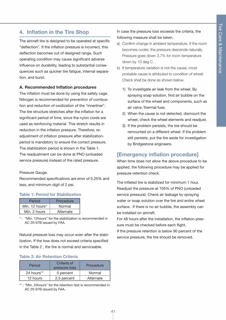
Table 1: Period for Stabilization
Period ProcedureMin. 12 hours* NormalMin. 2 hours Alternate
* : “Min. 12hours” for the stabilization is recommended in AC 20-97B issued by FAA.
Natural pressure loss may occur even after the stabi-
lization. If the loss does not exceed criteria specified
in the Table 2 , the tire is normal and serviceable.
Table 2: Air Retention Criteria
PeriodCriteria of
pressure lossProcedure
24 hours** 5 percent Normal12 hours 2.5 percent Alternate
** : “Min. 24hours” for the retention test is recommended in AC 20-97B issued by FAA.
In case the pressure loss exceeds the criteria, the
following measure shall be taken.
a) Confirm change in ambient temperature. If the room
becomes cooler, the pressure descends naturally.
Pressure goes down 3.7% for room temperature
down by 10 deg C.
b) If temperature variation is not the cause, most
probable cause is attributed to condition of wheel.
Check shall be done as shown below.
1) To investigate air leak from the wheel. By
spraying soap solution, find air bubble on the
surface of the wheel and components, such as
air valve, thermal fuse.
2) When the cause is not detected, dismount the
wheel, check the wheel elements and readjust.
3) If the problem persists, the tire should be
remounted on a different wheel. If the problem
still persists, put the tire aside for investigation
by Bridgestone engineers.
[Emergency inflation procedure]When time does not allow the above procedure to be
applied, the following procedure may be applied for
pressure retention check.
The inflated tire is stabilized for minimum 1 hour.
Readjust the pressure at 105% of PNO (unloaded
service pressure). Check air leakage by spraying
water or soap solution over the tire and entire wheel
surface. If there is no air bubble, the assembly can
be installed on aircraft.
For 48 hours after the installation, the inflation pres-
sure must be checked before each flight.
If the pressure retention is below 90 percent of the
service pressure, the tire should be removed.
42
Tire Care &
Maintenance
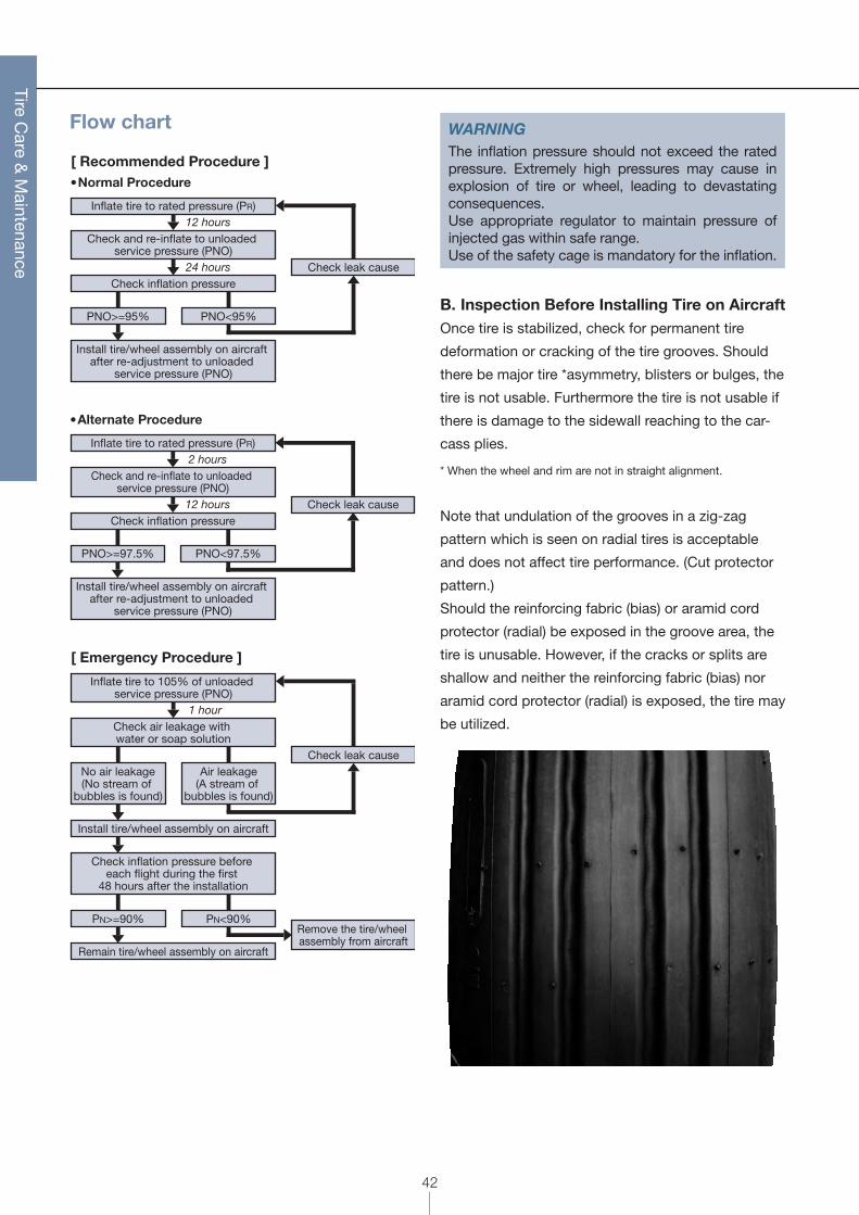
Flow chart
� Normal Procedure
Check leak cause
12 hours
24 hours
Inflate tire to rated pressure (PR)
Check inflation pressure
Check and re-inflate to unloaded service pressure (PNO)
PNO>=95% PNO<95%
Install tire/wheel assembly on aircraft after re-adjustment to unloaded
service pressure (PNO)
[ Recommended Procedure ]
� Alternate Procedure
Check leak cause
2 hours
12 hours
Inflate tire to rated pressure (PR)
Check inflation pressure
Check and re-inflate to unloaded service pressure (PNO)
PNO>=97.5% PNO<97.5%
Install tire/wheel assembly on aircraft after re-adjustment to unloaded
service pressure (PNO)
[ Emergency Procedure ]
Check leak cause
1 hour
Inflate tire to 105% of unloaded service pressure (PNO)
Check air leakage with water or soap solution
No air leakage(No stream of
bubbles is found)
Air leakage(A stream of
bubbles is found)
Install tire/wheel assembly on aircraft
Check inflation pressure before each flight during the first
48 hours after the installation
PN>=90% PN<90%
Remain tire/wheel assembly on aircraft
Remove the tire/wheel assembly from aircraft
WARNINGThe inflation pressure should not exceed the rated pressure. Extremely high pressures may cause in explosion of tire or wheel, leading to devastating consequences.Use appropriate regulator to maintain pressure of injected gas within safe range.Use of the safety cage is mandatory for the inflation.
B. Inspection Before Installing Tire on AircraftOnce tire is stabilized, check for permanent tire
deformation or cracking of the tire grooves. Should
there be major tire *asymmetry, blisters or bulges, the
tire is not usable. Furthermore the tire is not usable if
there is damage to the sidewall reaching to the car-
cass plies.
* When the wheel and rim are not in straight alignment.
Note that undulation of the grooves in a zig-zag
pattern which is seen on radial tires is acceptable
and does not affect tire performance. (Cut protector
pattern.)
Should the reinforcing fabric (bias) or aramid cord
protector (radial) be exposed in the groove area, the
tire is unusable. However, if the cracks or splits are
shallow and neither the reinforcing fabric (bias) nor
aramid cord protector (radial) is exposed, the tire may
be utilized.
43
Tire Care &
Maintenance
5. Inflation Pressure Control
It is recommended that inflation pressure of each
aircraft tire be checked daily, and that the pressure
gauge be calibrated regularly. Maintaining correct tire
inflation pressure is the most important factor in any
preventive maintenance program.
A. Pressure Readjustment After Installing Tire
on AircraftPNZ (loaded service pressure) shall be used instead
of the PNO, if the aircraft is on the ground.
PNZ is specified as add 4% to the PNO, to adjust the
target pressure considering increase by small shrink
of tire gas chamber due to vertical loading.
• Aircraft on Jacks: Readjustment pressure is PNO
• Aircraft on Wheels: Readjustment pressure is PNZ
1.045PNO (Unloaded)=PNZ (Loaded)
B. Pressure Control In ServiceThe pressure check should be done exclusively with
“cold tire”; tire temperature is within a rage of ambi-
ent temperature.
If the tire is not operated for successive 3 hours or
longer, the tire is granted as the “cold tire”, unless
otherwise exposed to direct sun light for a significant
time period.
C. Normal Pressure Loss During ServiceSlight pressure loss occurs with aircraft tires due to
natural leakage of small amount of gas. Permissible
range of the loss is 5% or less within 24 hours.
A small amount of gas diffusion through the “vent
holes”; artificial holes situated at the lower sidewall,
is a normal mechanism to bleed off trapped air, pre-
venting internal separation or blistering. However,
such air leakage should not be detectable by hand. If
pressure is found to be less than the minimum pres-
sure, refer to Table 3.
Table 3: Tire Pressure Verification
Tire Pressure Verification Recommended Action
P > PN +5% Overinflation Readjust to maximum of normal operating range if tire is at ambient temperature.
PN + 5% > P > PN Normal Operating Range No action if within Normal Operating Range (NOR).
PN > P > 95%PN Allowable Daily Pressure Loss Reinflate to specified service pressure.95%PN > P > 90%PN Moderate Pressure Loss Reinflate to specified service pressure. Record in aircraft log
book. Remove if pressure loss reoccurs within 24 hours.90%PN > P > 80%PN Large Pressure Loss Replace the tire.
80%PN > P > 0 Extreme Pressure Loss(Underinflation) Replace tire and its axle mate.
P = 0Complete pressure loss due to;• Tire perforation• Blown fuse plug
Replace tire and its axle mate.
P: Tire Pressure ReadingPN: Loaded Service PressureNOR: Normal Operating Range (Service Pressure)
* Please mark pressure loss tire with “tire pressure loss removal” or “low pressure”.
44
Tire Care &
Maintenance
D. Identification of Axle MateWhen a tire is removed for any of the following rea-
sons, the axle mate tire must be identified and the
serial number must be provided to the appropriate
retreader (Refer to Table 3).
1. Large pressure loss
2. Extreme pressure loss
3. Perforation
4. Blown fuse plugs
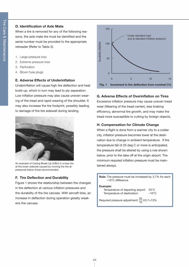
E. Adverse Effects of UnderinflationUnderinflation will cause high tire deflection and heat
build-up, which in turn may lead to ply separation.
Low inflation pressure may also cause uneven wear-
ing of the tread and rapid wearing of the shoulder. It
may also increase the tire footprint, possibly leading
to damage of the tire sidewall during landing.
An example of Casing Break Up (CBU) in a bias tire at the lower sidewall caused by running the tire at pressures below those recommended.
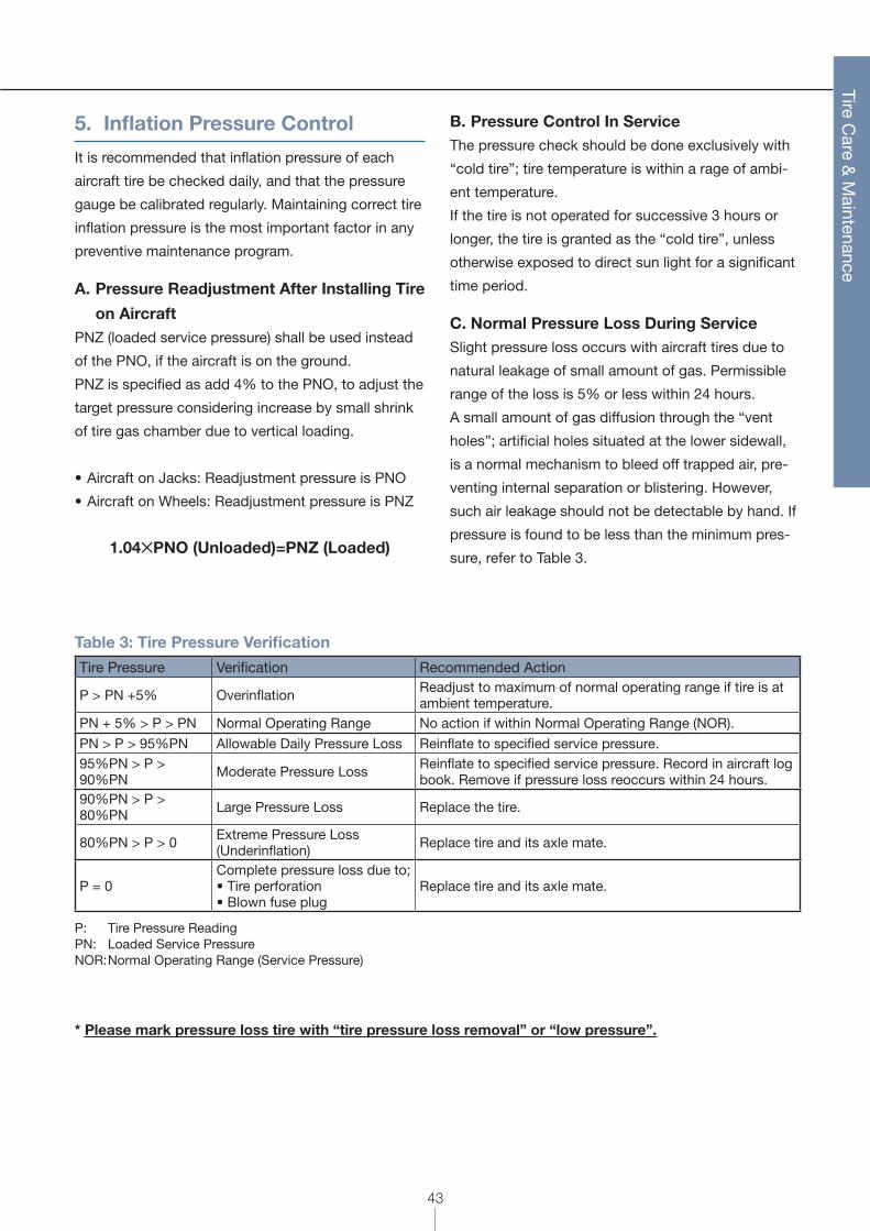
F. Tire Deflection and DurabilityFigure 1 shows the relationship between the changes
in tire deflection at various inflation pressures and
the durability of the tire carcass. With aircraft tires, an
increase in deflection during operation greatly weak-
ens the carcass.
Under standard loadand at standard inflation pressure
*
150
50
0
0 5 10 15
Dur
abili
ty (I
ND
EX
)
100
Fig. 1 Increment in tire deflection from nominal (%)
G. Adverse Effects of Overinflation on TiresExcessive inflation pressure may cause uneven tread
wear (Wearing of the tread center), less braking
efficiency, abnormal tire growth, and may make the
tread more susceptible to cutting by foreign objects.
H. Compensation for Climate ChangeWhen a flight is done from a warmer city to a colder
city, inflation pressure becomes lower at the desti-
nation due to change in ambient temperature. If the
temperature fall of 25 deg C or more is anticipated,
the pressure shall be altered by using a rule shown
below, prior to the take off at the origin airport. The
minimum required inflation pressure must be main-
tained always.
Rule: Tire pressure must be increased by 3.7% for each –10°C difference.
Example: Temperature of departing airport: 25°C Temperature of destination: –10°C
Required pressure adjustment: 3510
53.7=13%
45
Tire Care &
Maintenance
I. Pressure Control for “Hot Tires”A “Hot Tire” is defined to be a tire heated by aircraft
operation (Braking) or by exposure to sunlight and
having a surface temperature higher than ambient
temperature by at least 30°C. A “Hot Tire” may also
result from operating with an abnormally large tire
deflection.
If a “Hot Tire” is identified, the following actions
should be taken:
• Compare tire pressure for tires of the same gear
(nose or main gear). Tire pressure should be in
the same range for all tires on the same gear and
always greater than PNZ. Tire pressure can be
much greater than PNZ+5% after long taxiing or
severe braking maneuvers. Leave the tire in service.
• Tire pressure should always be greater than PNZ.
If pressure is lower than PNZ, conduct pressure
verification after cooling of the tire in accordance
with Table 3 (p43).
• If all tire pressures are greater than PNZ, but not all
in the same range (unusually large variation), check
for brake malfunctions or incorrect pressure adjust-
ment during a previous check.
Duration of time
50
020
Tem
per
atur
e (˚C
)
40 60 80 (Minutes)
Crown part
Bead part100
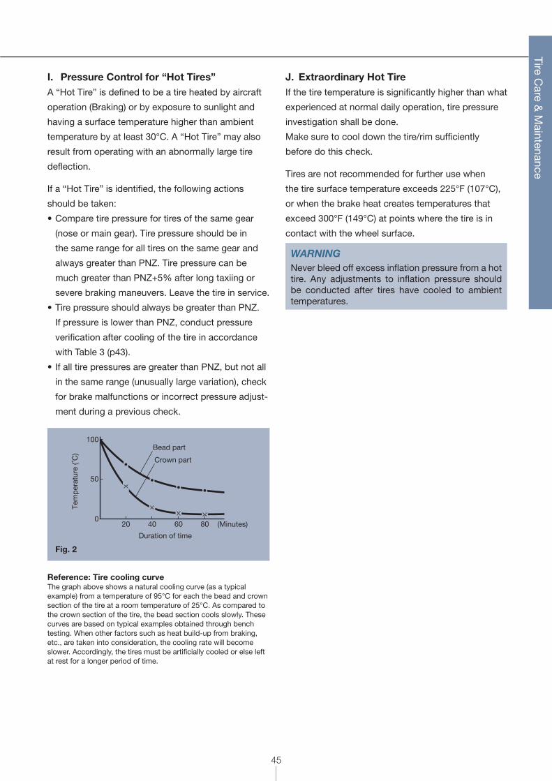
Fig. 2
Reference: Tire cooling curveThe graph above shows a natural cooling curve (as a typical example) from a temperature of 95°C for each the bead and crown section of the tire at a room temperature of 25°C. As compared to the crown section of the tire, the bead section cools slowly. These curves are based on typical examples obtained through bench testing. When other factors such as heat build-up from braking, etc., are taken into consideration, the cooling rate will become slower. Accordingly, the tires must be artificially cooled or else left at rest for a longer period of time.
J. Extraordinary Hot TireIf the tire temperature is significantly higher than what
experienced at normal daily operation, tire pressure
investigation shall be done.
Make sure to cool down the tire/rim sufficiently
before do this check.
Tires are not recommended for further use when
the tire surface temperature exceeds 225°F (107°C),
or when the brake heat creates temperatures that
exceed 300°F (149°C) at points where the tire is in
contact with the wheel surface.
WARNINGNever bleed off excess inflation pressure from a hot tire. Any adjustments to inflation pressure should be conducted after tires have cooled to ambient temperatures.
46
Tire Care &
Maintenance
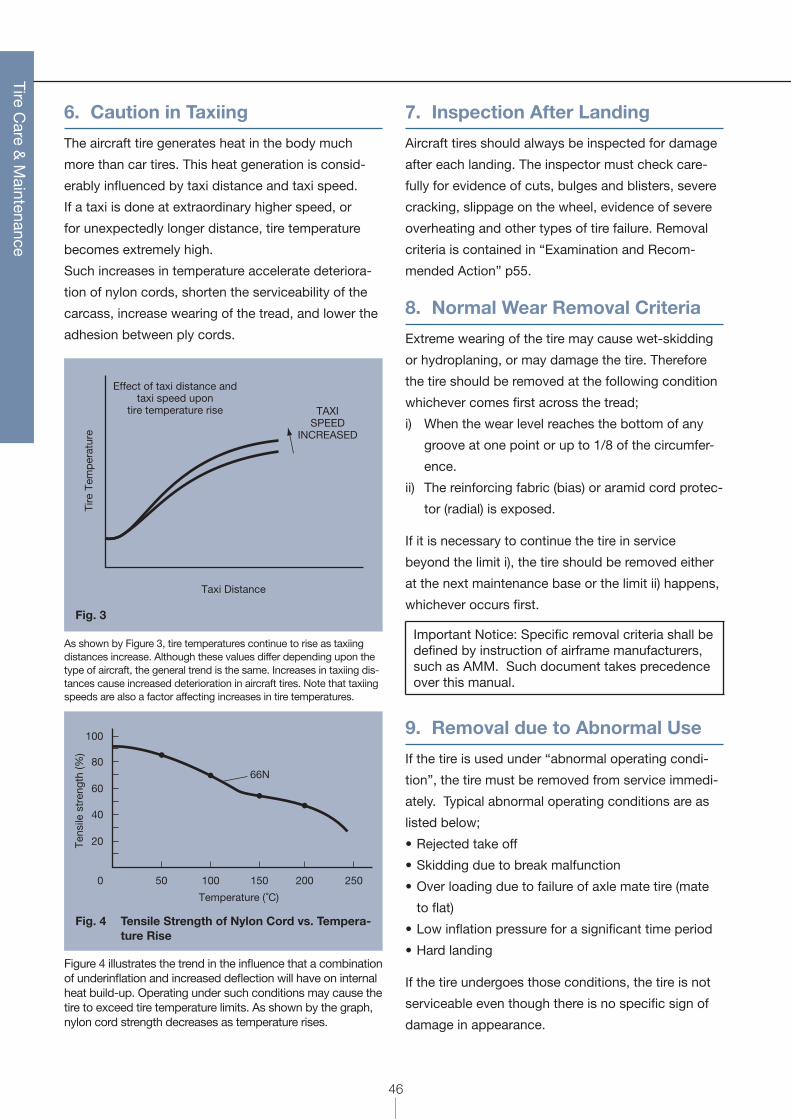
6. Caution in Taxiing
The aircraft tire generates heat in the body much
more than car tires. This heat generation is consid-
erably influenced by taxi distance and taxi speed.
If a taxi is done at extraordinary higher speed, or
for unexpectedly longer distance, tire temperature
becomes extremely high.
Such increases in temperature accelerate deteriora-
tion of nylon cords, shorten the serviceability of the
carcass, increase wearing of the tread, and lower the
adhesion between ply cords.
Taxi Distance
Tire
Tem
per
atur
e
TAXISPEED
INCREASED
Effect of taxi distance andtaxi speed upon
tire temperature rise
Fig. 3
As shown by Figure 3, tire temperatures continue to rise as taxiing distances increase. Although these values differ depending upon the type of aircraft, the general trend is the same. Increases in taxiing dis-tances cause increased deterioration in aircraft tires. Note that taxiing speeds are also a factor affecting increases in tire temperatures.
20
50
Tens
ile s
tren
gth
(%)
Temperature (˚C)
40
60
80
100
100 150 200 2500
66N
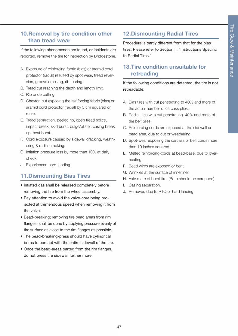
Fig. 4 Tensile Strength of Nylon Cord vs. Tempera-ture Rise
Figure 4 illustrates the trend in the influence that a combination of underinflation and increased deflection will have on internal heat build-up. Operating under such conditions may cause the tire to exceed tire temperature limits. As shown by the graph, nylon cord strength decreases as temperature rises.
7. Inspection After Landing
Aircraft tires should always be inspected for damage
after each landing. The inspector must check care-
fully for evidence of cuts, bulges and blisters, severe
cracking, slippage on the wheel, evidence of severe
overheating and other types of tire failure. Removal
criteria is contained in “Examination and Recom-
mended Action” p55.
8. Normal Wear Removal Criteria
Extreme wearing of the tire may cause wet-skidding
or hydroplaning, or may damage the tire. Therefore
the tire should be removed at the following condition
whichever comes first across the tread;
i) When the wear level reaches the bottom of any
groove at one point or up to 1/8 of the circumfer-
ence.
ii) The reinforcing fabric (bias) or aramid cord protec-
tor (radial) is exposed.
If it is necessary to continue the tire in service
beyond the limit i), the tire should be removed either
at the next maintenance base or the limit ii) happens,
whichever occurs first.
Important Notice: Specific removal criteria shall be defined by instruction of airframe manufacturers, such as AMM. Such document takes precedence over this manual.
9. Removal due to Abnormal Use
If the tire is used under “abnormal operating condi-
tion”, the tire must be removed from service immedi-
ately. Typical abnormal operating conditions are as
listed below;
• Rejected take off
• Skidding due to break malfunction
• Over loading due to failure of axle mate tire (mate
to flat)
• Low inflation pressure for a significant time period
• Hard landing
If the tire undergoes those conditions, the tire is not
serviceable even though there is no specific sign of
damage in appearance.
47
Tire Care &
Maintenance
10. Removal by tire condition other than tread wear
If the following phenomenon are found, or incidents are
reported, remove the tire for inspection by Bridgestone.
A. Exposure of reinforcing fabric (bias) or aramid cord
protector (radial) resulted by spot wear, tread rever-
sion, groove cracking, rib tearing.
B. Tread cut reaching the depth and length limit.
C. Rib undercutting.
D. Chevron cut exposing the reinforcing fabric (bias) or
aramid cord protector (radial) by 5 cm squared or
more.
E. Tread separation, peeled rib, open tread splice,
impact break, skid burst, bulge/blister, casing break
up, heat burst.
F. Cord exposure caused by sidewall cracking, weath-
ering & radial cracking.
G. Inflation pressure loss by more than 10% at daily
check.
J. Experienced hard-landing.
11. Dismounting Bias Tires
• Inflated gas shall be released completely before
removing the tire from the wheel assembly.
• Pay attention to avoid the valve-core being pro-
jected at tremendous speed when removing it from
the valve.
• Bead-breaking; removing tire bead areas from rim
flanges, shall be done by applying pressure evenly at
tire surface as close to the rim flanges as possible.
• The bead-breaking-press should have cylindrical
brims to contact with the entire sidewall of the tire.
• Once the bead-areas parted from the rim flanges,
do not press tire sidewall further more.
12. Dismounting Radial Tires
Procedure is partly different from that for the bias
tires. Please refer to Section II, “Instructions Specific
to Radial Tires.”
13. Tire condition unsuitable for retreading
If the following conditions are detected, the tire is not
retreadable.
A. Bias tires with cut penetrating to 40% and more of
the actual number of carcass plies.
B. Radial tires with cut penetrating 40% and more of
the belt plies.
C. Reinforcing cords are exposed at the sidewall or
bead area, due to cut or weathering.
D. Spot-wear exposing the carcass or belt cords more
than 10 inches squared.
E. Melted reinforcing-cords at bead-base, due to over-
heating.
F. Bead wires are exposed or bent.
G. Wrinkles at the surface of innerliner.
H. Axle mate of burst tire. (Both should be scrapped).
I. Casing separation.
J. Removed due to RTO or hard landing.
48
Tire Care &
Maintenance
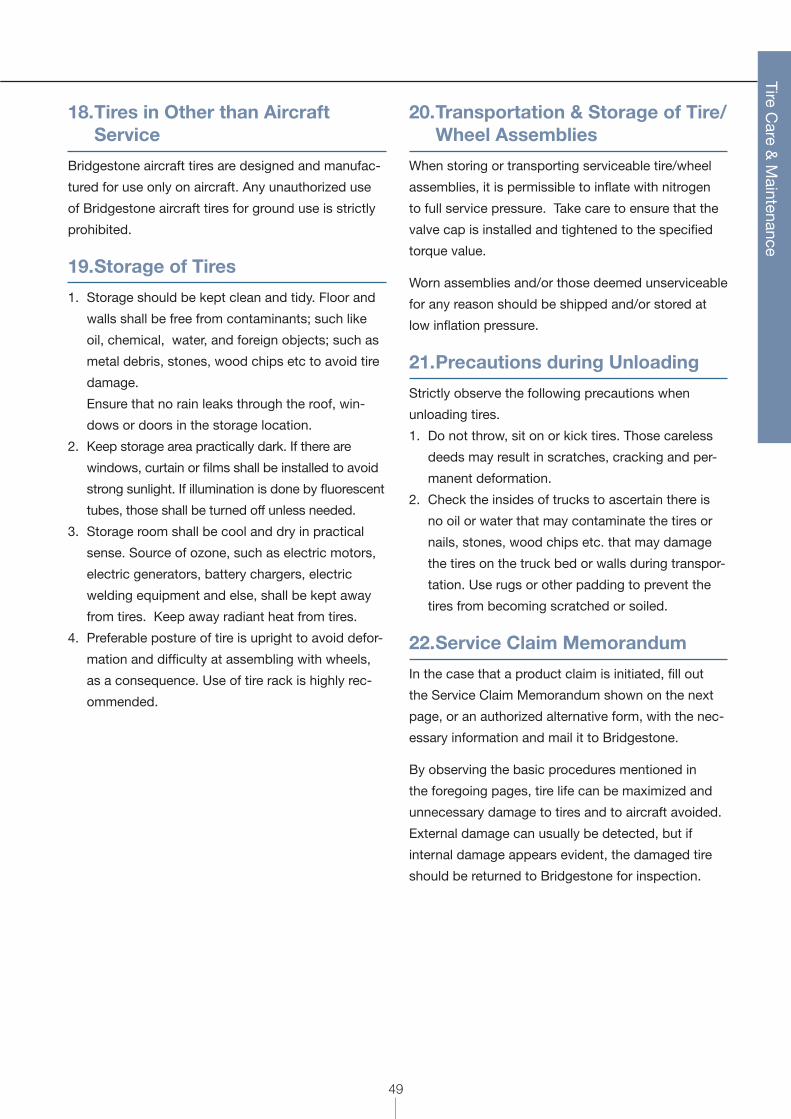
14. Matching Tire Diameters
Axle mate tires ought to have close outside-diame-
ters, in order to equalize vertical load bearing.
Recommended tolerance of the diameter difference
for the inflated tire is listed in the Table 4.
Table 4
Tire Outside Diameter Inch (mm)
Maximum Tolerance Inch (mm)
Up to 24" (610) 1/4" (6.4)24~32 (611~813) 5/16" (7.9)32~40 (814~1016) 3/8" (9.5)40~48 (1017~1219) 7/16" (11.1)48~55 (1220~1397) 1/2" (12.7)55~65 (1398~1651) 9/16" (14.3)66~over (1652~over) 5/8" (15.9)
15. Tire Flat-spot
• If an aircraft is grounded for a long period of time,
the tire deformation becomes “permanent” and flat
spot remains at the tread area even after the verti-
cal load is removed.
• The flat spot tends to occur more easily at lower
ambient temperature.
• For most of the case, the distortion disappears
during taxi, however, if significant vibration remains
detected, the tire should be removed from service.
• To prevent permanent flat-spot, it is recommended
to place the aircraft on jacks or roll the tire period-
ically when parked the aircraft for a long period of
time.
16. Protection from Contamination
Care should be taken that tires do not come into
contact with oil, gasoline, jet fuel, hydraulic fluids or
similar hydrocarbons. Such substances have dete-
riorating effects on rubber. When servicing aircraft,
cover tires. Be especially careful not to stand or lay
tires on floors that are covered with these contami-
nants.
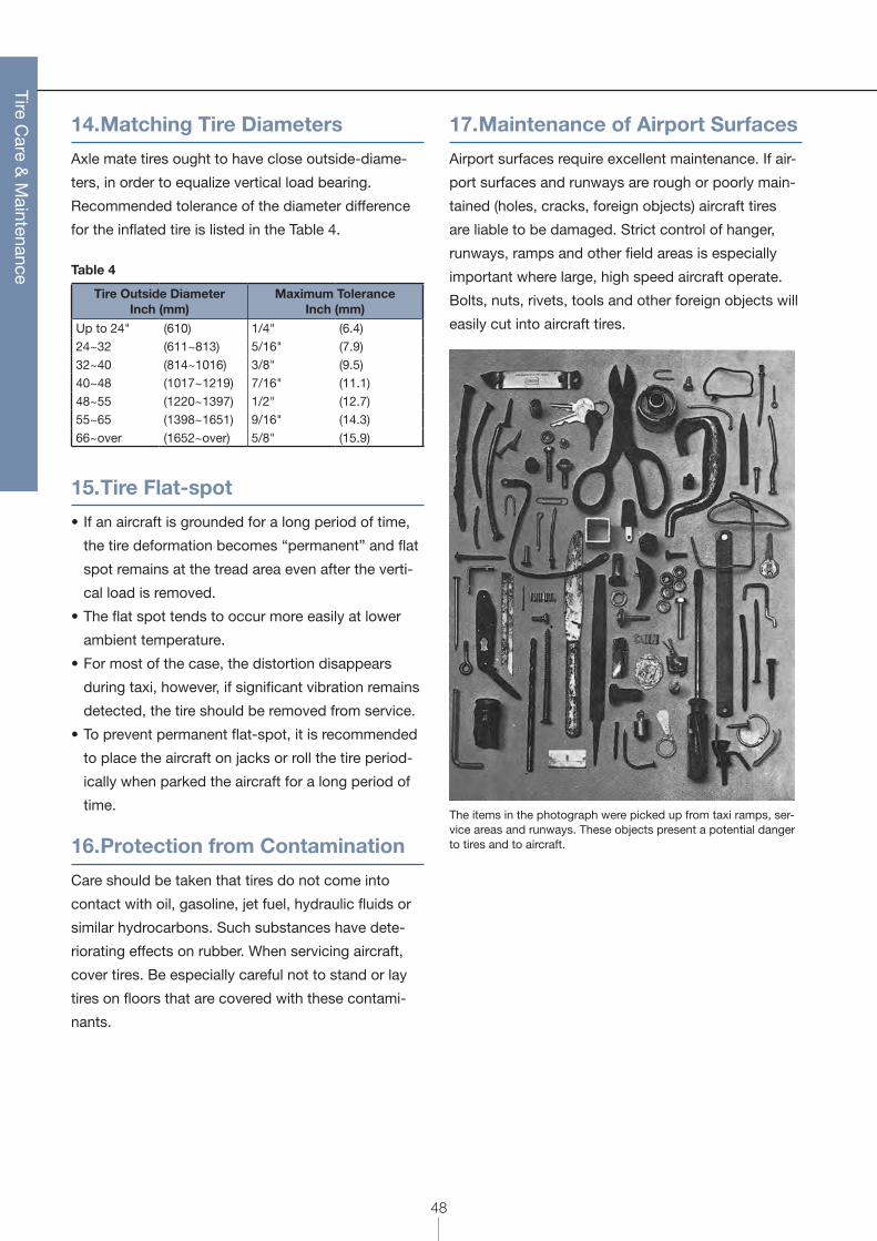
17. Maintenance of Airport Surfaces
Airport surfaces require excellent maintenance. If air-
port surfaces and runways are rough or poorly main-
tained (holes, cracks, foreign objects) aircraft tires
are liable to be damaged. Strict control of hanger,
runways, ramps and other field areas is especially
important where large, high speed aircraft operate.
Bolts, nuts, rivets, tools and other foreign objects will
easily cut into aircraft tires.
The items in the photograph were picked up from taxi ramps, ser-vice areas and runways. These objects present a potential danger to tires and to aircraft.
49
Tire Care &
Maintenance
18. Tires in Other than Aircraft Service
Bridgestone aircraft tires are designed and manufac-
tured for use only on aircraft. Any unauthorized use
of Bridgestone aircraft tires for ground use is strictly
prohibited.
19. Storage of Tires
1. Storage should be kept clean and tidy. Floor and
walls shall be free from contaminants; such like
oil, chemical, water, and foreign objects; such as
metal debris, stones, wood chips etc to avoid tire
damage.
Ensure that no rain leaks through the roof, win-
dows or doors in the storage location.
2. Keep storage area practically dark. If there are
windows, curtain or films shall be installed to avoid
strong sunlight. If illumination is done by fluorescent
tubes, those shall be turned off unless needed.
3. Storage room shall be cool and dry in practical
sense. Source of ozone, such as electric motors,
electric generators, battery chargers, electric
welding equipment and else, shall be kept away
from tires. Keep away radiant heat from tires.
4. Preferable posture of tire is upright to avoid defor-
mation and difficulty at assembling with wheels,
as a consequence. Use of tire rack is highly rec-
ommended.
20. Transportation & Storage of Tire/Wheel Assemblies
When storing or transporting serviceable tire/wheel
assemblies, it is permissible to inflate with nitrogen
to full service pressure. Take care to ensure that the
valve cap is installed and tightened to the specified
torque value.
Worn assemblies and/or those deemed unserviceable
for any reason should be shipped and/or stored at
low inflation pressure.
21. Precautions during Unloading
Strictly observe the following precautions when
unloading tires.
1. Do not throw, sit on or kick tires. Those careless
deeds may result in scratches, cracking and per-
manent deformation.
2. Check the insides of trucks to ascertain there is
no oil or water that may contaminate the tires or
nails, stones, wood chips etc. that may damage
the tires on the truck bed or walls during transpor-
tation. Use rugs or other padding to prevent the
tires from becoming scratched or soiled.
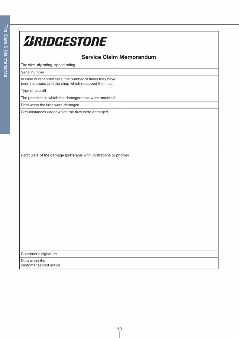
22. Service Claim Memorandum
In the case that a product claim is initiated, fill out
the Service Claim Memorandum shown on the next
page, or an authorized alternative form, with the nec-
essary information and mail it to Bridgestone.
By observing the basic procedures mentioned in
the foregoing pages, tire life can be maximized and
unnecessary damage to tires and to aircraft avoided.
External damage can usually be detected, but if
internal damage appears evident, the damaged tire
should be returned to Bridgestone for inspection.
50
Tire Care &
Maintenance
Service Claim MemorandumTire size, ply rating, speed rating
Serial number
Type of aircraft
The positions in which the dameged tires were mounted
Date when the tires were damaged
Circumstances under which the tires were damaged
Particulars of the damage (preferably with illustrations or photos)
Customer’s signature
Date when the customer served notice
In case of recapped tires, the number of times they havebeen recapped and the shop which recapped them last
51
Tire Care &
Maintenance
The care and maintenance of bias and radial tires is for the most part very similar. However, it is necessary to
emphasize certain important differences.
1. Radial Tire Mixability
When operated under similar conditions, radial air-
craft tires may exhibit different characteristics than
those of bias aircraft tires. Bridgestone recommends
that the following guidelines be heeded.
a. Aircraft need to be certified for use of radial tires in
place of bias or vice versa. Questions arising con-
cerning the certification of a given aircraft must be
taken up with the airframe manufacturer.
b. Radial tires should not be mounted on wheels
designed for bias ply tires or bias tires on wheels
designed for radial tires without first checking with
the wheel or airframe manufacturer.
Mixability of Bridgestone radial tires with bias tires
is permitted only as expressly stated in the official
airframe manufacturer’s bulletin or specification. Any
other use in unauthorized by Bridgestone Corporation.
2. Radial Tire Dismounting Procedure
A. DeflationBefore dismounting the tire from the wheel, com-
pletely release all remaining inflation pressure.
Remove the valve core only after all pressure has
been relieved.
WARNINGRemoval of the wheel valve core on an inflated tire could project the core with dangerous speed and force.
B. Recommended Bead-breaker Press DesignThe lower sidewalls of radial aircraft tires are signifi-
cantly more flexible than those of bias tires, and are
easily damaged by inappropriate dismounting pro-
cedures and/or equipment. For dismounting radial
aircraft tires from their wheels, Bridgestone recom-
mends the use of either a full-circle ring or a conical
pressure roller to ease the tire beads away from the
wheel flanges.
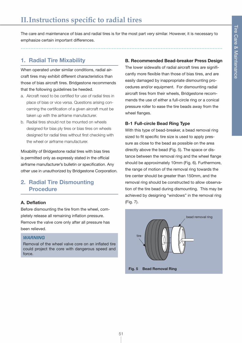
B-1 Full-circle Bead Ring TypeWith this type of bead-breaker, a bead removal ring
sized to fit specific tire size is used to apply pres-
sure as close to the bead as possible on the area
directly above the bead (Fig. 5). The space or dis-
tance between the removal ring and the wheel flange
should be approximately 10mm (Fig. 6). Furthermore,
the range of motion of the removal ring towards the
tire center should be greater than 150mm, and the
removal ring should be constructed to allow observa-
tion of the tire bead during dismounting. This may be
achieved by designing “windows” in the removal ring
(Fig. 7).
tire
bead removal ring
Fig. 5 Bead Removal Ring
II. Instructions specific to radial tires
52
Tire Care &
Maintenance
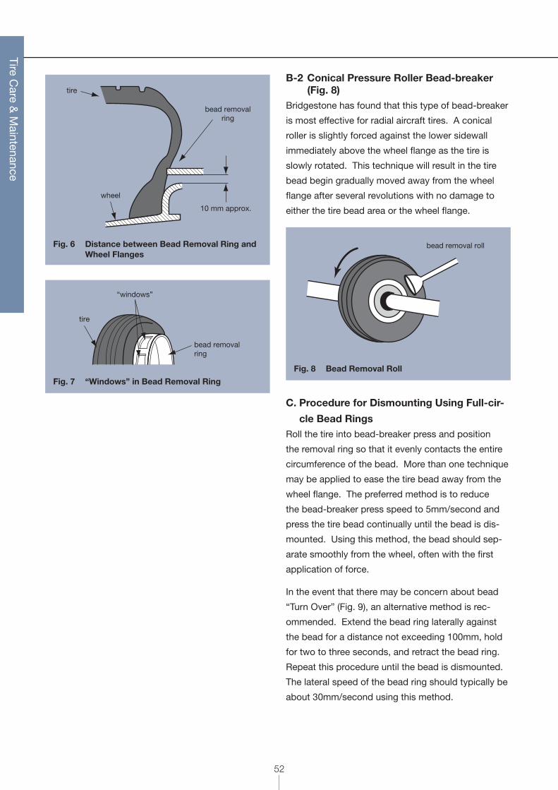
10 mm approx.
bead removalring
wheel
tire
Fig. 6 Distance between Bead Removal Ring and Wheel Flanges
bead removalring
tire
“windows”
Fig. 7 “Windows” in Bead Removal Ring
B-2 Conical Pressure Roller Bead-breaker (Fig. 8)
Bridgestone has found that this type of bead-breaker
is most effective for radial aircraft tires. A conical
roller is slightly forced against the lower sidewall
immediately above the wheel flange as the tire is
slowly rotated. This technique will result in the tire
bead begin gradually moved away from the wheel
flange after several revolutions with no damage to
either the tire bead area or the wheel flange.
bead removal roll
Fig. 8 Bead Removal Roll
C. Procedure for Dismounting Using Full-cir-
cle Bead RingsRoll the tire into bead-breaker press and position
the removal ring so that it evenly contacts the entire
circumference of the bead. More than one technique
may be applied to ease the tire bead away from the
wheel flange. The preferred method is to reduce
the bead-breaker press speed to 5mm/second and
press the tire bead continually until the bead is dis-
mounted. Using this method, the bead should sep-
arate smoothly from the wheel, often with the first
application of force.
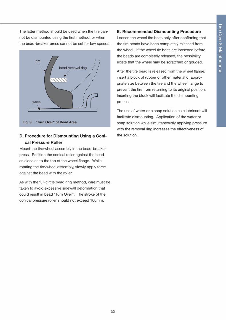
In the event that there may be concern about bead
“Turn Over” (Fig. 9), an alternative method is rec-
ommended. Extend the bead ring laterally against
the bead for a distance not exceeding 100mm, hold
for two to three seconds, and retract the bead ring.
Repeat this procedure until the bead is dismounted.
The lateral speed of the bead ring should typically be
about 30mm/second using this method.
53
Tire Care &
Maintenance
The latter method should be used when the tire can-
not be dismounted using the first method, or when
the bead-breaker press cannot be set for low speeds.
wheel
bead removal ring
tire
Fig. 9 “Turn Over” of Bead Area
D. Procedure for Dismounting Using a Coni-
cal Pressure RollerMount the tire/wheel assembly in the bead-breaker
press. Position the conical roller against the bead
as close as to the top of the wheel flange. While
rotating the tire/wheel assembly, slowly apply force
against the bead with the roller.
As with the full-circle bead ring method, care must be
taken to avoid excessive sidewall deformation that
could result in bead “Turn Over”. The stroke of the
conical pressure roller should not exceed 100mm.
E. Recommended Dismounting ProcedureLoosen the wheel tire bolts only after confirming that
the tire beads have been completely released from
the wheel. If the wheel tie bolts are loosened before
the beads are completely released, the possibility
exists that the wheel may be scratched or gouged.
After the tire bead is released from the wheel flange,
insert a block of rubber or other material of appro-
priate size between the tire and the wheel flange to
prevent the tire from returning to its original position.
Inserting the block will facilitate the dismounting
process.
The use of water or a soap solution as a lubricant will
facilitate dismounting. Application of the water or
soap solution while simultaneously applying pressure
with the removal ring increases the effectiveness of
the solution.