Embed Size (px)
Citation preview
i
“I hereby declare that I have read through this report entitle “Wireless Alert System For
Machine” and found that it has comply the partial fulfillment for awarding the degree of
Bachelor of Electrical Engineering (Power Electronic and Drives)”
Signature : ………………………………..
Supervisor‟s Name : Nur Maisarah Bt Mohd Sobran
Date : 27 June 2012
ii
WIRELESS ALERT SYSTEM FOR MACHINE
AMINATUL MUNAUWARAH BINTI YAHAYA
A report submitted in partial fulfillment of the requirements for the degree
of Power Electronic and Drives
Faculty of Electrical Engineering
UNIVERSITI TEKNIKAL MALAYSIA MELAKA
2011/2012
iii
I declare that this report entitle “Wireless Alert System For Machine” is the result of my own
research except as cited in the references. The report has not been accepted for any degree
and is not concurrently submitted in candidature of any other degree.
Signature : .................................................
Name : Aminatul Munauwarah Binti Yahaya
Date : 27 June 2012
iv
ACKNOWLEDGEMENT
First and foremost, I thank Allah the Almighty for blessing me to complete my Final
Year Project 2. I want to take this opportunity to record my utmost and sincere gratitude to
my supervisor, Miss Nur Maisarah Binti Mohd Sobran. Without her, I can never start work
on my project and to proceed until this point of development. She has shown me guidance,
important advice, and inspiration throughout my project. She has also given me knowledge
essential in doing this project.
Besides, I would like to show my appreciation to my lecturers. Who have taught me
over the years in UTem. They have taught me the basic of Electrical Engineering, and this
invaluable knowledge has provided me a firm foundation for doing this project. Most
importantly, the knowledge I required from them has prepared me for my career in the future.
Furthermore, I would like to thank my friends and fellow classmates for sharing and
discussing knowledge with me. Their support, opinion and advised either direct or indirect
will be not forgotten.
To my beloved family, I would like to forward my obliged to them for their
continuous support during my study period, their patience and benevolence. Lastly, I would
like to thank everyone who has contributed during my Final Year Project 2. Your kindness
and cooperation of my paperwork is much appreciated.
v
ABSTRACT
Machine breakdown is a common phenomenon in a factory. This problem will affect
the product quality and quantities for that day production. Machine condition monitoring is
important to improve factory efficiency. Thus immediate action must be made in order to
make sure factory will not facing any losses due to defect products. The same situation
happens in Fujitsu factory that situated in Batu Pahat. From observation at Fujitsu factory, it
is difficult to make sure twenty four hours machine monitoring could be done in person. Thus
this project will provide the solution for Fujitsu problems where an alert system will be
develop to detect which machine having a breakdown and immediately send the short
message system (SMS) to the authorize person.
Machines at Fujitsu factory will produce warning signal when error occur. The
Transmitter of Radio Frequency (RF) remote control that located near the machine will sent
the error to Receiver of Radio Frequency (RF) that located in control room and immediately
SMS were send to authorize person by using GSM. At the same time, alarm will be trigger
and LED light turns on to indicate which machines are having a breakdown.
This Wireless Alert System For Machine project, can be shown that one alert system
for Fujitsu machine are developed by using Radio Frequency (RF) remote control transmitter
and receiver successfully achieved the main objective which is person in charge was able to
get the message using SMS and it definitely can inform the person in charge if have the
machine breakdown occurred. The person in charge also will know that machine at the part
production breakdown by the alarm unit in the maintenance room. So, they also can trace
which machine having breakdown based on the LED display. Other than that, the system
also able to give warning to person in charge wirelessly via GSM modem.
vi
ABSTRAK
Kerosakan pada mesin merupakan satu fenomena yang biasa berlaku di sesebuah
kilang. Masalah ini akan memberi kesan terhadap kualiti produk dan kuantiti untuk
pengeluaran pada hari tersebut. Pemantauan terhadap mesin adalah penting untuk
memperbaiki kecekapan kilang. Oleh itu, tindakan segera perlu diambil untuk memastikan
supaya kilang tersebut tidak berhadapan dengan sebarang masalah yang disebabkan oleh
kecacatan pada produk. Ini menjurus kepada situasi yang sama berlaku kepada kilang Fujitsu,
Batu Pahat Johor. Daripada pemerhatian saya di kilang tersebut, keadaan ini adalah sukar
untuk membuat pemantauan dan memastikan bahawa mesin tersebut boleh beroperasi selama
24 jam sehari secara perseorangan.
Oleh itu, projek ini dibuat bagi menyelesaikan permasalahan yang berlaku di kilang
Fujitsu, dimana satu isyarat sistem akan dibina untuk mengesan mesin yang mana mengalami
kerosakan dan serta-merta menghantar sistem pesanan ringkas kepada pihak yang
bertanggungjawab.
Apabila ralat berlaku, mesin tersebut akan menghasilkan isyarat amaran. Pemancar
frekuensi radio berkawalan jauh yang terletak berhampiran dengan mesin akan menghantar
isyarat kepada penerima frekuensi radio yang terletak di dalam bilik selenggaraan dan ia akan
segera menghantar sistem pesanan ringkas kepada orang yang bertanggungjawab dengan
menggunakan GSM modem. Pada masa yang sama, penggera akan memicu dan serentak
dengan itu lampu LED akan dihidupkan untuk menunjukkan mana satu mesin yang
menghadapi masalah kerosakan.
Projek “Wireless Alert System For Machine “ ini dapat menunjukkan bahawa satu
sistem amaran untuk mesin di kilang Fujitsu dengan menggunakan pemancar frekuensi radio
dan penerima frekuensi radio telah berjaya dilaksanakan berdasarkan kepada tujuan asal
projek ini dilaksanakan. Orang yang bertanggungjawab akan mengetahui bahawa mesin di
bahagian produksi berlaku kerosakan berdasarkan kepada penggera yang terhasil di dalam

vii
bilik selenggaraan. Maka, mereka dapat mengenalpasti mana satu mesin yang mengalami
masalah berdasarkan kepada paparan LED tersebut. Selain daripada itu, sistem ini juga
mampu untuk memberi amaran kepada orang yang bertanggungjawab sekiranya beliau
berada di luar kawasan dengan kaedah tanpa wayar iaitu menggunakan GSM modem kepada
telefon bimbit.
viii
TABLE OF CONTENTS
CHAPTER TITLE PAGE
ACKNOWLEDGEMENT iv
ABSTRACT v
ABSTRAK vi
TABLE OF CONTENTS viii
LIST OF TABLES xi
LIST OF FIGURES xii
LIST OF ABBREVIATIONS xiv
LIST OF APPENDICES xv
1 INTRODUCTION 1
1.1 Project Background 2
1.2 Problem Statement 3
1.3 Project Objective 3
1.4 Project Scope 3
2 LITERATURE REVIEW 5
2.1 Case Study 6
2.1.1 Case Study 1 6
2.1.2 Case Study 2 7
ix
2.1.3 Case Study 3 7
2.1.4 Case Study 4 8
2.1.5 Case Study 5 8
2.1.6 Case Study 6 8
2.2 Wireless Alert System for Machine 9
2.2.1 Short Message Service(SMS) 9
2.2.2 GSM modem Technology 10
2.2.3 Radio Frequency Transmitter and
Receiver 11
2.2.4 Alarm Unit 11
2.2.5 Light Emitting Diode (LEDs) 12
3 METHODOLOGY 13
3.1 Introduction 13
3.2 Hardware Design 15
3.2.1 Power Supply 17
3.2.2 Relay 18
3.2.3 ULN2803 IC 20
3.2.4 Microcontroller PIC16F877A 21
3.2.5 Machine Detection Unit 22
3.2.6 Radio Frequency Transmitter and Receiver 22
3.2.7 Alarm unit 22
3.2.8 Light Emitting Diode (LEDs) 23
3.2.9 GSM modem Technology 24
3.2.10 Mobile Phone 24
x
3.3 Circuit Design 26
3.3.1 The PIC16F877A 27
3.3.2 Voltage Regulator 28
3.4 Software Implementation 28
3.4.1 MicroBasic for Microchip PIC
Microcontroller 28
3.4.2 Proteus 7 Professional 29
4 RESULT AND ANALYSIS 30
4.1 Overall result of this project 30
4.2 Analysis result for LEDs sequences 32
4.3 Result for GSM Modem 34
5 CONCLUSION 36
5.1 Introduction 36
5.2 Conclusion 36
5.3 Suggestion for further work 37
REFERENCES 39
APPENDICES 41
xi
LIST OF TABLES
TABLE TITLE PAGE
Table 2.1 Some AT Commands relevant to Short Message 6
Table 3.1 Ports and description of PIC16F877A 27
Table 4.1 Sequences for the LED result 32
Table 4.2 Result from GSM Modem 34
xii
LIST OF FIGURES
FIGURE TITLE PAGE
Figure 3.1 Flow chart diagram of project 14
Figure 3.2 Block diagram of Wireless Alert System for Machine 16
Figure 3.3 Power supply unit and its usage in this project 17
Figure 3.4 Relay Switch Connection; NC: Normally Close, NO:
Normally Open, COM: Common 18
Figure 3.5 (a) ULN2803 Logic Diagram 20
Figure 3.5 (b) Schematic Diagram (Each Darlington Pair) 20
Figure 3.6 Pin diagram PIC16F877A Microcontroller 21
Figure 3.7 Block diagram for GSM Modem 24
Figure 3.8 The Main Board Circuit 26
Figure 3.9 PCB Design for Main Board 26
Figure 3.10 MikroBasic user friendly environment 29
Figure 4.1 Measuring voltage at indicator lamp by using
Multimeter 30
Figure 4.2 Manual methods to determine the retrieving signal from
transmitter to receiver. 31
xiii
Figure 4.3 The flow of circuitry when the machine breakdown 31
Figure 4.4 LED for display unit 33
Figure 4.5 GSM Modem 34
Figure 4.6 The SMS receive from GSM Modem 35
xiv
LIST OF ABBREVIATIONS
GSM Global System for Mobile Communication
LED Light Emitting Diode
LCD Liquid Crystal Display
MCU Microcontroller Unit
PIC Peripheral Interface Unit
SIM Subscriber Identity Module
RF Radio Frequency
SMS Short Message Services
PCB Printed Circuit Board
GND Ground
VCC Common Collector Voltage
Vpp Power from reset
XTAL Crystal
TX Transmitter
RX Receiver
M meter
V Volt
A Ampere
MHZ Mega Hertz

xv
LIST OF APPENDICES
APPENDIX TITLE PAGE
A Wireless Alert System for Machine programming 41
1
CHAPTER 1
INTRODUCTION
Machinery already becomes a backbone to factory in producing quality product.
Failure of machines may not only lead to a loss of production, but also, in some serious
situations, may cause human casualties. If the industry has more than one machines, it
difficult to find which one machine that have an error unless person in charge for the machine
was informed that the machine have an error. This situation will take longer time to take an
action. Based on the previous system technology the machine will connect to the authorized
person computer using wired system. This situation can minimize the time but it needs more
costs in installation and maintenance. This system is widely used in many industries in the
country, but these systems have their own disadvantage, that is why this project was purpose.
This project has been developed to detect error machine. So that after detect the error
machine, the operator can immediately diagnose a fault system in the processes of identifying
a machine‟s operating condition and investigate its possible source of fault. These processes
can help factories to reduce their overall production costs, improve the production reliability,
minimize machine downtime, and increase operational efficiency.
2
1.1. Project Background
There are several types of machine error detection alarm systems. The first
one is the error detect by the alarm that produce by certain machine which have an
error. This system does not have a mechanism to inform the technician to take an
action to repair the machine. So this is the biggest disadvantage because to take a long
time to inform an authorized person to repair the machine. The second one is machine
error is appearing at the authorized computer. The authorized person knows the
machine have an error by reading the message at the computer. This system able to
inform the technician which machine that has an error if the technician read the
message. This system is not really effective if the technician did not read the message
at the computer or he is at another place.
A variety of voltage signals analysis techniques have been used to diagnosis
machine status. Contingency plans can be provided to reduce the loss of production
due to unexpected breakdown of production machines. So, this based on this project
Wireless alert system for machine will detect the voltage signal from the machine.
The voltage signal from the machine will activate the relay and the signal will sent to
the main controller board by using RF transmitter and receiver. The main controller
board will activate alarm unit to emit aloud alarm sound after receive signal from RF
receiver. The main role of LED light is to display, so person in charge know which
machine are breakdown. At the same time message will sent to authorized person to
take an action. This project makes the installation of wireless alert system easier than
the commercial alert system using wire cable.
3
1.2. Problem Statement
In Fujitsu factory, machines always facing breakdown, so operator have to take a long
time to tell to maintenance engineer when defect occurs in that machine. This case becomes
more complicated when engineer maintenance is not in production line or not in maintenance
room. Thus this will provide alert system via GSM.
Fujitsu did not have enough budget to buy an expensive machine which is automatically
detect an error. So, an engineer give an idea to develop the project which is can be applied at
the machine to trigger machine error.
1.3. Objectives
i. To develop an alert system for machine this is connected by using Radio Frequency
(RF) Transmitter and Receiver.
ii. To develop a wireless system using GSM Modem to warning the personal in
charge/authorize person.
iii. To develop a circuitry for a wireless alert system.
1.4. Scope
To ensure this project achievable and realistic of the objectives that in require, so this project
necessary cater to scope as follows:
i. The first part is concerning to the distance between machine breakdown which is can
send signals from radio frequency transmitter to the radio frequency receiver in scope
over 30 meters.
4
ii. The second part is determined number of machine can trace. So the maximum
machine that can trace was two units. The machine have been choose based on the
frequence machine have an error occurred. This system use PIC microcontroller as
overall guard.PIC microcontroller used to give aloud warning sound system and led
will be display which machine are breakdown and short messaging system (SMS)
trigger to the mobile phone person in charge so that system can operate by systematic.
5
CHAPTER 2
LITERATURE REVIEW
This project was created to improve the idea from the previous project. The literature
review for this project is important to study the previous project and the components that
used on this project.
A case study is a research methodology common in social science. It is based on an in-
depth investigation of a single individual, group, or event to explore causation in order to find
underlying principles. Case study should be defined as a research strategy, an empirical
inquiry that investigates a phenomenon within its real-life context. Case study research means
single and multiple case studies, can include quantitative evidence, relies on multiple sources
of evidence and benefits from the prior development of theoretical propositions. It provides a
systematic way of looking at events, collecting data, analyzing information, and reporting the
results.
As a result the researcher may gain a sharpened understanding of why the instance
happened as it did, and what might become important to look at more extensively in future
research. Case studies lend themselves to both generating and testing hypotheses. In this
project, there are some cases that can be referring in doing this project. Each case is shown
below.
6
2.1 Case Study
2.1.1 Case Study 1
In 2010, Huiping Huang [1] develops a project „A Remote Home Security System
Based on Wireless Sensor Network and GSM Technology‟. Data collecting unit consists of
motion sensor, heat sensor, smoke sensor and gas sensor which is detect some parameter and
will convert to another signal. This data collecting unit would be sent signal to main control
board to activated the alarm by using wireless system. After main control board receive
signal from detection unit it would be send signal to GSM Modem to enable GSM Modem
sending Short Messaging Service (SMS) to the house owner‟s mobile phone when some
dangerous condition has been detected. To setting the GSM Modem, there are some AT
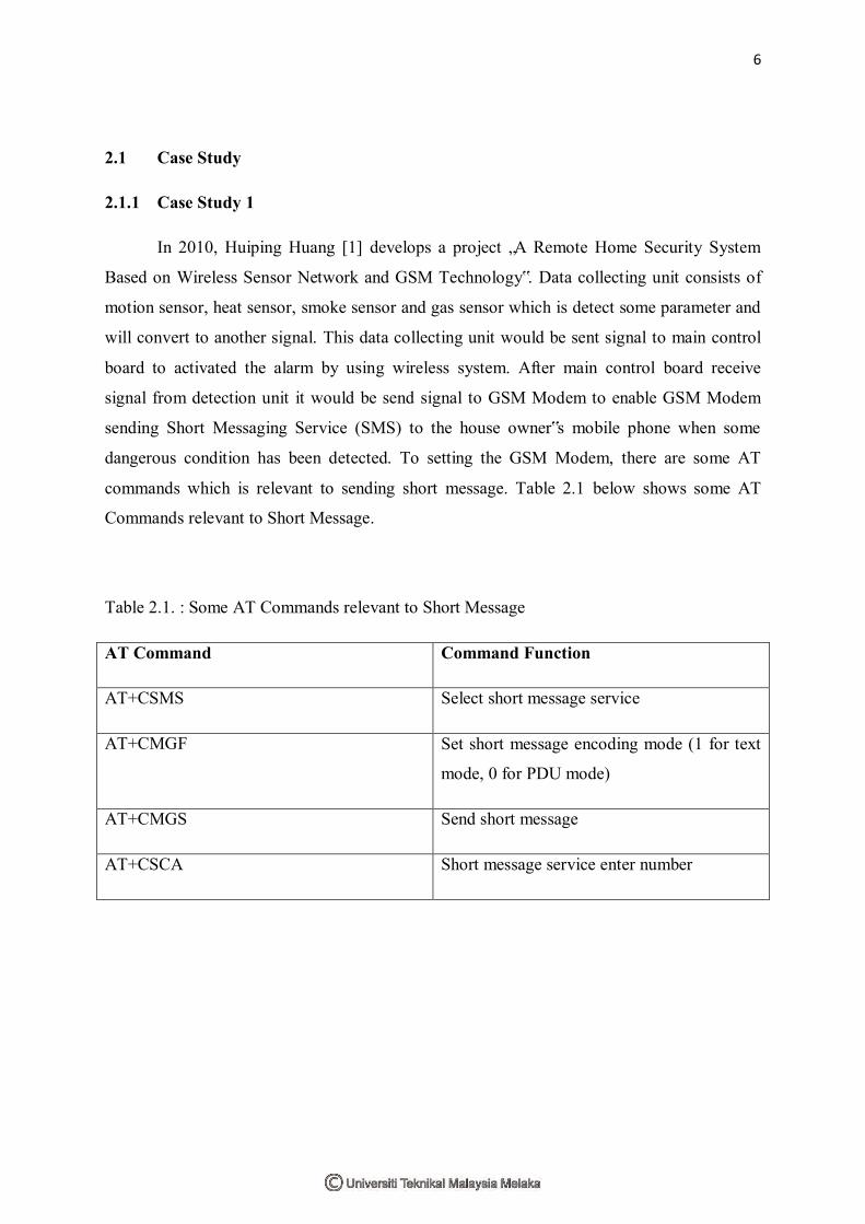
commands which is relevant to sending short message. Table 2.1 below shows some AT
Commands relevant to Short Message.
Table 2.1. : Some AT Commands relevant to Short Message
AT Command Command Function
AT+CSMS Select short message service
AT+CMGF Set short message encoding mode (1 for text
mode, 0 for PDU mode)
AT+CMGS Send short message
AT+CSCA Short message service enter number
7
2.1.2 Case Study 2
In 2011, Luay Fraiwan Khaldon Lweesy, Aya Bani- Salma and Nour Mani [2],
develops a project “A Wireless Home Safety Gas Leakage Detection System” It consists of a
few units such as sensing unit, transmission data unit and receiver data unit. Smoke sensor
attach at the kitchen by using LPG gas. It will be function when gas sensor detect an
excessive gas. The system consists of two major of two major modules: the gas leakage
detection and transmission module, and the receiver module. The gas leakage detection and
transmission module detects the change in concentration of LPG and natural gas and activates
an audiovisual alarm when it exceeds a certain voltage. Furthermore, it sends another alarm
message through a radio frequency (RF) system to the receiver module. The receiver module
is a mobile unit that could be placed anywhere within the premises of the house so that the
alarm can be detected and heard at a distance from the place of gas leakage.
2.1.3 Case Study 3
In 2005, Lian Ai Fang [3], develops a project “ Mobile Fire Alert with SMS”. This
system consists of fire detection system. This system of fire detection unit, alarm unit, water
pump unit and display unit. There are three sensors and three water pumps used in the
system. When a fire occurs, the sensors will send signal to the main control board, where a
microcontroller is used to control the system. At the same time, the alarm will emit a loud
siren to alert the house occupants and the panel will display location where the fire occurs.
Then, it is followed by the water pump which will discharge water to put out the fire. A
message will also be sent to the house inmate‟s mobile phone. So that he/she could make
necessary actions.
8
2.1.4 Case Study 4
In 2011, Wan Adlin Harris Wan Mohd Asmara and Noor Hafizah Abdul Aziz [4],
develops a project “SMS Flood Alert System. The project abaout remote water level alarm
system developed by applying liquid sensors and GSM technology. This system focuses on
monitoring water level remotely and utilizes Global System of Mobile Connections (GSM)
and Short Message Service (SMS) to convey data from sensors to the respective users
through their mobile phone. The hardware of the system includes Micro Controller Unit
(MCU) PIC18F452. There are three part which is liquid sensors, Inverter and Easygate GSM
Module. This system used C compiler software through AT commands.
2.1.5 Case Study 5
In 2010, Zaid bin Sulaiman [5], develops a project “ Wireless Fire Alarm System
Using Smoke detector and Heat sensor”. This project consist of several main parts such as
two sensor (heat and smoke ), main control board, power supply, alarm unit, water pump unit,
display unit and mobile phone. This project would be function when detector detect some
heat or smoke at the occur place. This sensor sending a signal to main control board by using
radio frequency (remote Control RF). After that, the main control board will send signal to
the alarm unit to activate the alarm (siren). At the same time, main control board will send the
signal through to GSM Modem to be enable GSM Modem for sending Short Message
Service(SMS) to the authorize‟s mobile phone.
2.1.6 Case Study 6
In 2004, Mohammad Sharizan Bin Safuan [6], develops a project “ Sistem Amaran
Banjir Automatik Berasaskan Teknologi SMS”. Initially this system to detect the level of
water and will automatically send signals to GSM Modem circuit when the water level had
reach a certain warning level. The signal will be prosessed and then the GSM Modem circuit
will send a warning message via mobile phone using SMS. At the same time, the LCD
display and siren will be activated. The system will only be activated automatically when the
water level reaches certain warning level, so that the users will not be annoyed by this system
all the time
9
2.2 Wireless Alert System for Machine
From the previous project that already done, this Wireless Alert System for Machine
project has decided to use component such as relay (24V), RF remote control, PIC
microcontroller, buzzer and GSM modem to developed this project. These projects use a
relay as a switch which is to trigger the RF remote control to send a signal to the main control
board. This relay will be operate when it receive a voltage from the indicator lamp at the
machine detection unit. RF remote controls have been choosing because it more relevant than
the wired system and it also can reduce the maintenance cost when installations are made.
This project use a PIC basic programming to set PIC microcontroller to make sure that GSM
modem can send the right message to the authorize person when machine error occurred. By
using PIC microcontroller it easier to be write-erase until thousand times. It also consists of
40 pin by 33 paths of input and output. These project also using a GSM modem because
GSM modem would be to send short message system (SMS) to the authorized person mobile
phone. GSM Modem can be a quick and efficient way to get started with SMS, because a
special subscription to a short message service provider is not required. In most parts of the
world, GSM Modems are cost effective solution for receiving SMS messages. To make sure
the person in charge in the maintenance room concern that machine having breakdown so this
project use a buzzer as a output to emit loud sound. This buzzer very effective and available
in the market.
2.2.1 Short Message Services (SMS)
Short message services (SMS) is the transmission of short text message to and a
mobile phone, fax machine, and message must be no longer than 160 alphanumeric
characters and contain no images or graphic. The short message service, in other words, short
message are not send directly from sender to recipient, but always via SMS center (SMSC)
instead [3]. Each mobile phone network that supports SMS has one or more messaging centre
to handle and manage the short messages. Short messages can be sent and received by
simultaneously with GSM voice, data and fax calls. This is possible because whereas voice,
data and fax call take over a dedicated radio channel using signaling path. As such user of
SMS rarely if ever busy or engaged signal during peak network usage time.