Embed Size (px)
Citation preview
FEATURE ARTICLE14 I Thermal News
MEETING THE HIGHER HEAT DENSITY CHALLENGE
The outdated belief that there is a ceiling of
around 6 kW of heat per cabinet that can effec-
tively be cooled by air is based on an accurate
assessment of the innate inefficiencies of stan-
dard hot aisle/at cold aisle data centers and a
poor understanding of the natural forces that can
be harnessed to remove heat from a cabinet. This
idea was based on an true understanding of the
fixed relationship between airflow, heat dissipa-
tion and temperature rise (CFM = 3.1W/ÄT) in
the context of a standard hot aisle/cold aisle data
center, where there is a dependency relationship
between the volume of cold air delivered through
a proximate perforated floor tile and a cabinet
server heat load, plus the presence of heated
server exhaust air in the room. The practical lim-
its to how much air you can push through a per-
forated floor tile and the looming presence of
heated return air conspire to limit how much can
be cooled in any particular cabinet.
Removing these constraints allows for higher
power/heat densities that can potentially be
cooled by air. In a data center where the cabinets
function as a complete isolation barrier between
supply and return air, these constraints are
removed. Complete isolation is accomplished
using a combination of passive air cooling acces-
sories such as blanking filler panels to block
bypass airflow, equipment mounting area
perimeter sealing air dams, floor-tile cut-out
brush seal grommets along with a system to
remove the return air from the room into a sus-
pended ceiling return air space. Such a system
would include a solid rear cabinet door with gas-
ket seal and a vertical exhaust duct running
between the cabinet and the suspended ceiling,
thus creating a ducted exhaust system using pas-
sive air cooling.
COMPLETE AIRFLOW ISOLATION By implementing a ducted exhaust system, hot
exhaust air no longer exists in the room and the
dependency on how much air can be pushed
through a
single per-
forated
floor tile is
eliminated,
allowing
cold air to
be deliv-
ered any-
where in
the room.
As heat
densities
increase
The Data Center Cooling Problem SOLVEDB y I a n S e a t o n , T e c h n o l o g y M a r k e t i n g M a n a g e r , C h a t s w o r t h P r o d u c t s , I n c .P a s s i v e a i r c o o l i n g s o l u t i o n s n o t o n l y o f f e r t h e m o s t e f f i c i e n t w a y t o c o o l t o d a y ’ s i n c r e a s i n g d e n s i t y r e q u i r e m e n t s , b u t p r e s e n th u g e e n e r g y s a v i n g s a n d a l o w e r i n i t i a l i n v e s t m e n t c o m p a r e d t o c l o s e - c o u p l e d a n d l i q u i d c o o l e d s o l u t i o n s . P a s s i v e a i r c o o l i n g c a ns u c c e s s f u l l y d i s s i p a t e a s m u c h h e a t a s c a n b e g e n e r a t e d b y c o m m e r c i a l s e r v e r s t h a t f i t i n t o a 4 2 t o 4 5 U c a b i n e t , a n d i n f a c tm o r e t h a n m o s t c l o s e - c o u p l e d a n d l i q u i d - c o o l e d s o l u t i o n s . B a s e d o n c o m p l e t e i s o l a t i o n b e t w e e n h o t e x h a u s t a n d c o o l s u p p l y a i r ,p a s s i v e a i r c o o l i n g s o l u t i o n s p r o v i d e a c c e s s t o l o w e r d a t a c e n t e r c o o l i n g , w h i c h t r a n s l a t e s i n t o i n c r e a s e d s u p p l y a i r t e m p e r a -t u r e s a n d d e c r e a s e d e n e r g y c o n s u m p t i o n .
Winter 08/09 I www.ThermalNews.com
Figure 1. Typical Cabinet, air re-circu-lates inside the cabinet and into the room.
www.ThermalNews.com I Winter 08/09
FEATURE ARTICLEThermal News I 15
beyond the level
that could practi-
cally be achieved
by under-floor air
delivery without
creating extra
wide cold aisles,
the access floor
can be eliminated
and the room can
be flooded with
high volumes of
cold air through
wall grates or
from overhead.
With the availability of theoretically infinite cooling
capacity, the remaining constraint revolves around effec-
tively removing the heat from the cabinet. While it is not
particularly prudent to reveal all the intellectual property
in this solution until all the patents are issued, suffice to
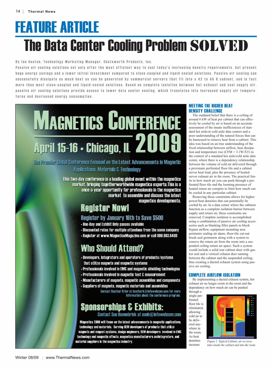
say that CPI Passive Cooling Solutions used
to form ducted exhaust systems utilize spe-
cific geometries that exploit the forces
of the Bernoulli Principle (inverse
relationship between velocity and
pressure) and generate a vortex with-
in the space to push hot exhaust air
up the back of the cabinet and into
the ceiling plenum. From the ceiling
plenum the hot exhaust air is direct-
ducted back to the CRAC unit,
cooled and then re-used as supply air
for the data center.
These ducted exhaust systems have
been deployed in large numbers in
working data centers with actual,
measured heat loads in excess of 20
kW per cabinet. Testing has surpassed
30 kW per cabinet and there is cur-
rently a customer project where cabi-
nets are being shipped into a space
where they will be loaded with 30 kW of actual, measured
server heat load. Further testing is planned to extend
beyond these levels and those reports will be forthcoming.
DUCTED EXHAUST CABINETS - THE ENERGYEFFICIENT CHOICE
More important than power density, is the cus-
tomer’s costs for cooling these densities, and there is
no more efficient, lower cost way of cooling a data
center than with the above-described ducted exhaust
system. The two basic factors affecting this higher effi-
ciency are 100 percent utilization of HVAC output and
an access path to more hours of economization cool-
ing. With the ducted exhaust system, every bit of cold
air produced by the HVAC system has to go through a
server – the only path between supply air and return air
is one of heat transfer through a server, so there is no
waste – there is no bypass airflow and no need for the
over-provisioning, which is required in standard hot
aisle/cold aisle data centers.
The efficiency claims of close-coupled and liquid-
cooled solutions are based on comparisons to inherent-
ly inefficient data centers with a high amount of bypass
airflow, and over-provisioning of cooling required by
the extreme variations in pressure and airflow through-
out a room. Because of the traditional dependencies on
air delivered through proximate perforated access floor
tiles, cooling capacity provisioning formulas have had
to plan for supplying adequate air to the lowest airflow
spot in a room, resulting in typically 200 to 300 per-
cent over-provisioning and huge amounts of wasted
bypass airflow. When it no longer matters where the
cold air is delivered and when 100 percent of the air
must travel through a server, there is no longer a need
for that over-provisioning and therefore no more waste.
While the elimination of waste may sound like it
puts a ducted exhaust system on an even playing field
with the close-coupled and liquid-cooled solutions, it
actually puts the ducted approach at an advantage
because of the higher efficiencies of the larger fans
and motors moving air at the room level.
The coefficient of performance (COP) for the larger
motors and fans of bigger free-standing CRAC units is
always going to be higher than the smaller motors and
fans of close-coupled solutions, and the COP of the
extremely large water-cooled central air handlers is
always going to be superior to anything small enough to
fit on the data center floor. This has always been the
case, but because of the historical waste of standard hot
aisle/cold aisle data centers, this COP advantage never
translated into comparable efficiencies on the data center
floor. With a ducted exhaust cabinet system that results
in 100 percent utilization of the HVAC output, these
superior COP values can now be translated directly into
data center cooling efficiency.
Free Cooling
Additional benefits of ducted exhaust systems
arise from chiller plant efficiencies and access to
more hours of “free” cooling. In a ducted exhaust
data center, only one temperature exists within the
room, so supply air temperatures no longer need to
be delivered in the mid-to-low 50’s. If equipment
standards allow for a 77°F server inlet temperature,
then the room can be cooled to 77°F with a 77°F
supply air temperature. The higher supply tempera-
ture dramatically improves chiller plant efficiency as
well as opens the door for access to significantly
more hours of economization cooling. Table 1
describes the temperature thresholds for three differ-
ent economization strategies.
With the higher supply temperatures allowed by
ducted exhaust systems, the data center operator
benefits from improved chiller plant efficiency –
approximately a 1 to 1.5 percent reduction in
chiller plant energy use for every 1° increase in the
chilled water loop temperature, or 25 to 35 percent
energy use reduction. In addition, these tempera-
tures allow for many more hours of economization
cooling – all hours under 60°F for water-side econ-
omization; all hours under 72°F for KyotoCooling
heat recovery wheel economization and all hours
under 77°F wet bulb for evaporative air-side econ-
omization. In a data center with a 2.0 Power
Utilization Effectiveness (PUE), water side econo-
mization and evaporative air-side can reduce the
total data center energy use by 35 percent during
those economization hours, and by 43 percent dur-
ing KyotoCooling hours.
In conclusion, the airflow isolation achieved
with ducted exhaust systems raises the bar by a
factor of 4 or 5 for heat densities and provides
much more efficient cooling at a lower initial
investment than close-coupled or liquid cooled
solutions. While a completely contained close-cou-
pled system could provide access to similar water-
side economization hours and chiller plant efficien-
cies, those solutions will, by definition have poorer
coefficient of performance ratings and will not be
able to provide access to the most economical
economization of KyotoCooling nor to the higher
number of economization hours of evaporative air-
side economization.
For more information, visit www.chatsworth.com
Most Data
Centers are Here
CRAC w/
Economizer
TIA-942
Best Practices
CRAC w/
Economizer
100% Isolation
Heat Recovery Wheel
100% Isolation
Evaporative Air
Economizer 100%
Isolation
Delivered 60-85°F 68-77°F 77°F 77°F 77°F
Supply 52-55°F 52-55°F 77°F 77°F 77°F
Water 42°F 42°F 65°F N/A 65°F
Ambient 37°F 37°F 60°F 72°F 77°F
Figure 2. Ducted Exhaust Cabinet,removes hot air from the cabinetand room.
Figure 3.CPIPassive CoolingSolutions installedin the F-SeriesTeraFrame CabinetSystem form a duct-ed exhaust cabinet.
Table 1.