Embed Size (px)
Citation preview

HyunJun Choi Aug 27, 2004
OPNET Simulator
HyunJun ChoiAug 27, 2004
Informational Communication University

HyunJun Choi Aug 27, 2004
Contents
• Modeling Overview• Process domain• Node domain• Project domain

HyunJun Choi Aug 27, 2004
What is OPNET?
• A powerful network simulation tool– comprehensive development environment for modeling of
communication networks and distributed systems– Accuracy and easy-of-use for network planner
• System requirements– Visual studio 6.0
• References– www.opnet.com– www.simus.net

HyunJun Choi Aug 27, 2004
Modeling Overview

HyunJun Choi Aug 27, 2004
Backgrounds
• Object orientation– OPNET Consists of objects, each with configurable sets of attribute– Objects Belong to classes
• Specialized in communication networks and information systems
• Graphical specification
• Flexibility to develop detailed custom models– OPNET provides a flexible, high-level programming language with
extensive support
• Automatic generation of simulations– Automatically compiled with C programming language
HyunJun Choi Aug 27, 2004
Typical Applications of OPNET
• Standards-based LAN and WAN performance modeling
• Internetworking planning
• Research and development in communications architectures and protocols
• Distributed sensor and control networks
• Mobil packet radio networks
• Satellite networks

HyunJun Choi Aug 27, 2004
OPNET simulator Architecture
Initial Specification
Analysis
Data Collection andSimulation
Re-Specification
Simulation Project Cycle

HyunJun Choi Aug 27, 2004
Specification Editors
• Project Editor– Specify network topology and configure nodes and links
• Node Editor– Create models of nodes by specifying internal structure and
capabilities– Combine modules
• Process Editor– Develop models of decision-making processes representing
protocols, algorithms, resource managers, operation systems, etc.
• Link Editor– Create, edit, and view link models
• Packet Format Editor– Specify packet format, defining the order, data type, and size of
fields contained within the packet
• ICI Editor– Create, edit, and view interface control information formats

HyunJun Choi Aug 27, 2004
Specification Editors (cont’d)
• PDF Editor– Create, edit, and view PDF
• Probe Editor– Identify sources of statistics and animation that are to be collected
during a simulation– Done before execution
• Simulation Tool– Design and run sequences of simulations, each potentially
configured with different inputs and/or outputs
• Analysis Tool– Plot and process numerical data generated by simulations

HyunJun Choi Aug 27, 2004
Graphical Editors for networks, node, and process models

HyunJun Choi Aug 27, 2004
Modeling domains
Domain Editor Modeling Focus
Network Project
Network topology described in terms of subnetworks, nodes, links, and geographical context.
Node Node
Node internal architecture described in terms of functional elements and data flow between them.
Process Process
Behavior of process (protocols, algorithms, applications), specified using finite state machines and extended high-level languages

HyunJun Choi Aug 27, 2004
Network domain example

HyunJun Choi Aug 27, 2004
Node domain example

HyunJun Choi Aug 27, 2004
Process domain example
HyunJun Choi Aug 27, 2004
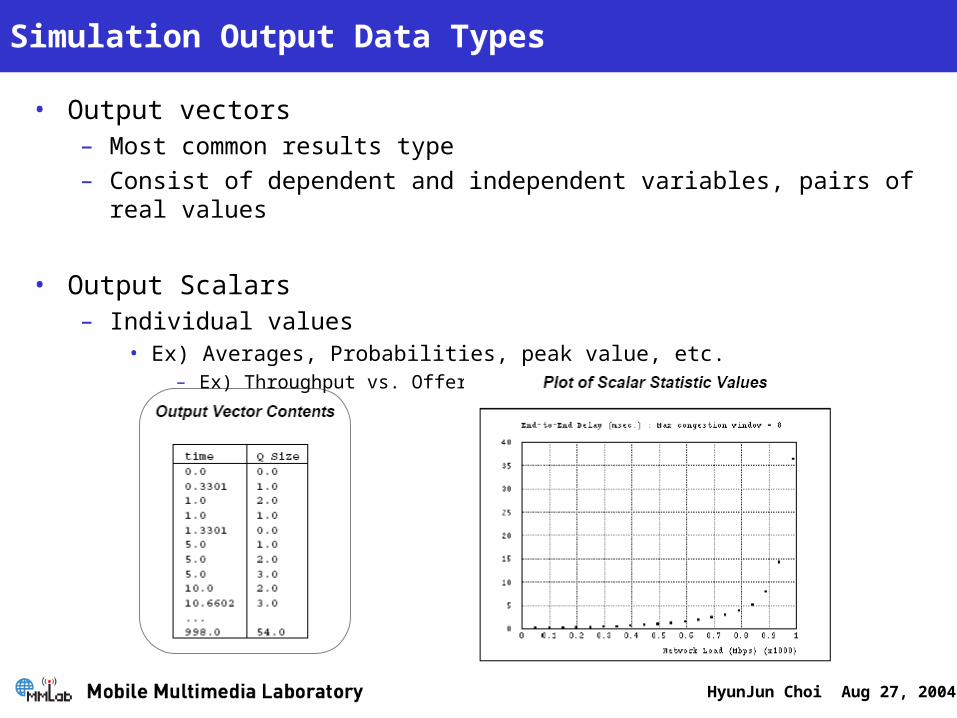
Simulation Output Data Types
• Output vectors– Most common results type– Consist of dependent and independent variables, pairs of real
values
• Output Scalars– Individual values
• Ex) Averages, Probabilities, peak value, etc.– Ex) Throughput vs. Offered Load

HyunJun Choi Aug 27, 2004
OPNET model hierarchy

HyunJun Choi Aug 27, 2004
Process domain

HyunJun Choi Aug 27, 2004
Process Model Example
• Sink Process

HyunJun Choi Aug 27, 2004
Interrupt-Driven Execution
• Process are driven by events– Internally or externally interrupted

HyunJun Choi Aug 27, 2004
Process Hierarchy
• Root process – Child process– Call KP Op_pro_create()

HyunJun Choi Aug 27, 2004
Interrupt Steering Example

HyunJun Choi Aug 27, 2004
Local Process Resources
• Input and Output Streams– Packet streams are objects in Node Editor and used to connect modules toge
ther– Packet streams connect source with destination modules which are called ou
tput and input streams
• Input stream to receiver process– op_intrpt_stream(), op_pk_get(), op_strm_pksize(),and etc.
• Output stream from sender process– Op_pk_send(), op_pk_send_delayed(), op_pk_send_forced(),and ect.

HyunJun Choi Aug 27, 2004
Graphical expression of Streams

HyunJun Choi Aug 27, 2004
Graphical expression of Streams (Cont’d)
Recall this picture!

HyunJun Choi Aug 27, 2004
State Transition diagram
• Proto-C models consist of two basic components– States and Transitions
• A process has two executives– Enter executive and Exit executive
• Forced and Unforced States– Forced State (Green)
• Proceeds without any event
– Unforced State (Red)• Pauses between enter and exit executives• Waits for interrupt to break
Blocked
Blocked
Enter
Enter
Exit
Exit
< Execution Flow Thorough Unforced States>

HyunJun Choi Aug 27, 2004
Execution Flow through Combination of Unforced and Forced States
Invocation starts at top of exit executives of unforced states
Invocation starts at bottom of Enter executives of unforced states

HyunJun Choi Aug 27, 2004
State Transition diagram (Cont’d)

HyunJun Choi Aug 27, 2004
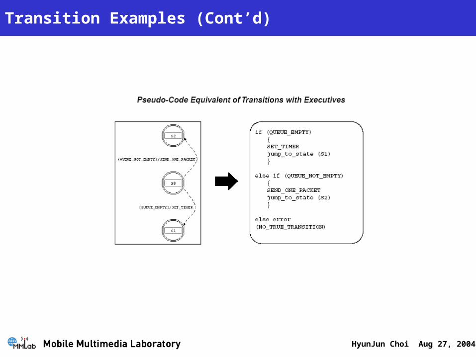
Initial state & transitions
• Initial state– Must be designed in each process model– Occur only once
• Transitions– Movement of a process from state to state and conditions under
which such changes may take places
(condition)/Executive

HyunJun Choi Aug 27, 2004
Transition Examples
HyunJun Choi Aug 27, 2004
Transition Examples (Cont’d)

HyunJun Choi Aug 27, 2004
Macro Definitions within Process Model Header Block

HyunJun Choi Aug 27, 2004
Variables
• State variable– Used to represent the information accumulated and retained by a
process– Require a memory allocation of corresponding size that will last as
long as the process exists
• Temporary variable– Used to store information that doesn’t require persistency– Doesn’t require additional memory
• Global variable– Used to provide a means for multiple processes in different
modules
HyunJun Choi Aug 27, 2004
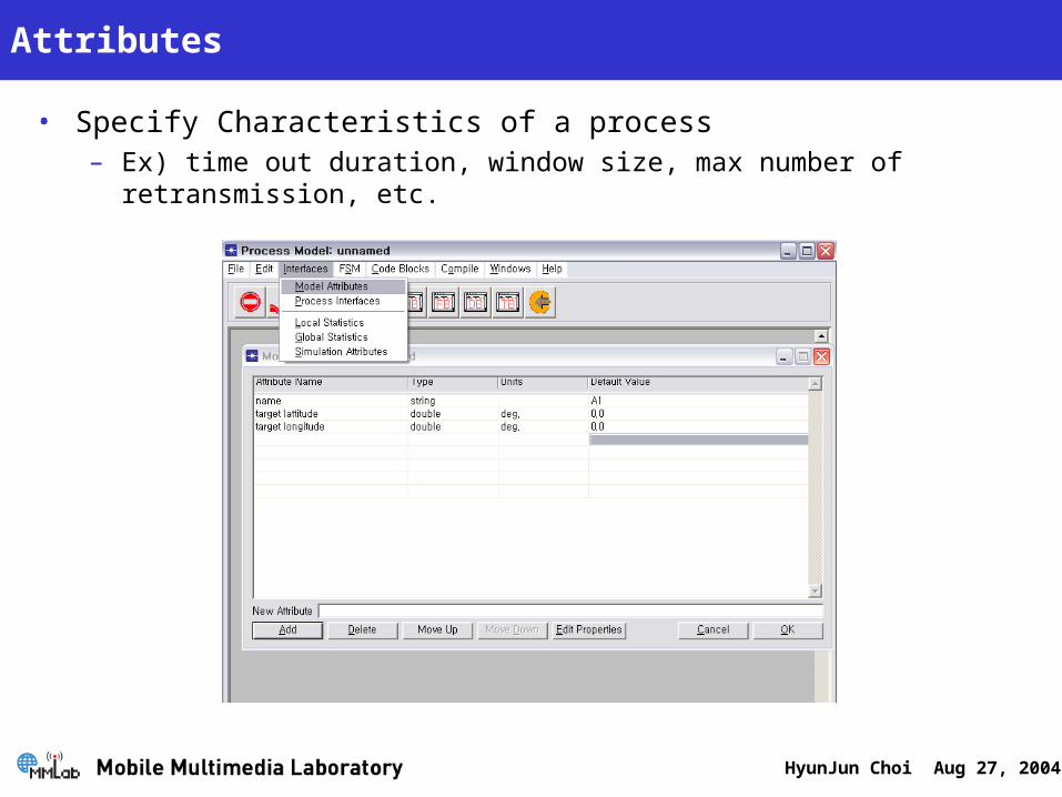
Attributes
• Specify Characteristics of a process – Ex) time out duration, window size, max number of retransmission,
etc.

HyunJun Choi Aug 27, 2004
Attributes usage example

HyunJun Choi Aug 27, 2004
Node Domain

HyunJun Choi Aug 27, 2004
Node modeler example
• Ethernet Lan

HyunJun Choi Aug 27, 2004
Typical Node Models
• Work station– Generate and receive transfers of files or sparse packets and
manage several concurrent network connections
• Packet switch– Supports large numbers of incoming and outgoing data links and
performs packet routing at high speeds
• Satellite terminal– Generates and receives packets according to a CA protocol
• Remote data sensor– Acts as a simple source of packets, usually transmitting them in
bursts

HyunJun Choi Aug 27, 2004
Module definition
• Processor modules– Primary general-purpose building blocks of node models– Can be specified by process model attribute– Used to perform general processing of data packets
• Queue modules– Provide superset of the functionality of processor modules– Are related to memories
HyunJun Choi Aug 27, 2004
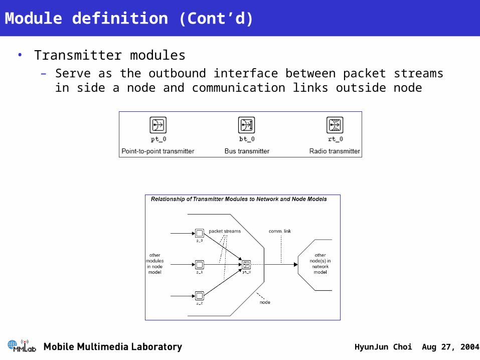
Module definition (Cont’d)
• Transmitter modules– Serve as the outbound interface between packet streams in side a
node and communication links outside node

HyunJun Choi Aug 27, 2004
Module definition (Cont’d)
• Receiver modules– Serve as the inbound interface between communication links
outside a node and packet streams inside the node

HyunJun Choi Aug 27, 2004
Connection definition
• Packet streams– Support the flow of data packets between modules– Three methods for transferring a packet and notifying arrivals
• Scheduled arrival– Is scheduled of the destination module– Occurs after all other events
• Forced arrival– Occurs immediately
• Quiet arrival– No stream interrupt occurs at all

HyunJun Choi Aug 27, 2004
Connection definition (Cont’d)
• Statistic wire– Unlike packet streams, it convey individual values– Individual values are used as an interface where the source module
and can share certain values with destination module – Each module within a node has a set of local input and output
statistics

HyunJun Choi Aug 27, 2004
Connection definition (Cont’d)
• Logical Associations– Do not actually carry data between modules– Do not exit during simulation, but used purely as specification
devices– Used to interpret structure
HyunJun Choi Aug 27, 2004
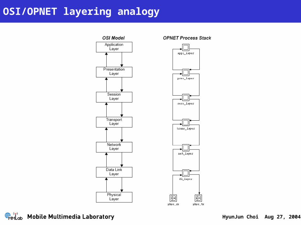
OSI/OPNET layering analogy

HyunJun Choi Aug 27, 2004
Network Domain
HyunJun Choi Aug 27, 2004
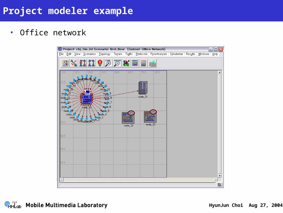
Project modeler example
• Office network

HyunJun Choi Aug 27, 2004
Network domain
• Define the overall scope of a system to be simulated• Size and scope of the networks modeled can range simple to
complex

HyunJun Choi Aug 27, 2004
Network objects
• Subnetworks– Provide a powerful mechanism to manipulate complex networks
structures and to break down the system’s complexity through abstractions
– Have Fixed, mobile, satellite types
HyunJun Choi Aug 27, 2004
Network objects (Cont’d)
• Communication nodes– Exits within a subnetwork and represents a network device with a
wide range of possible capabilities– Determined by node models– Have fixed, mobile, and satellite types

HyunJun Choi Aug 27, 2004
Network objects (Cont’d)
• Communication links– Allow communication of information between nodes in the form of
structured message called packets– Simplex, duplex point to point, bus and taps

HyunJun Choi Aug 27, 2004
Modeling node and subnetwork movement
• Trajectories– Vector based
• Direction and velocity
– segment based• Time and three dimension (x, y and altitude)
HyunJun Choi Aug 27, 2004
Simulation time-packet switching-