Embed Size (px)
Citation preview
1
HYDROGEN STORAGE – INDUSTRIAL PROSPECTIVES
Barthélémy, H.Air Liquide, 75 Quai d’Orsay, Paris, 75007, France, [email protected]
ABSTRACTThe topic of this paper is to give an historical and technical overview of hydrogen storage vessels andto detail the specific issues and constraints of hydrogen energy uses. Hydrogen, as an industrial gas, isstored either as a compressed or as a refrigerated liquefied gas. Since the beginning of the last century,hydrogen is stored in seamless steel cylinders. At the end of the 60s, tubes also made of seamlesssteels were used; specific attention was paid to hydrogen embrittlement in the 70s. Aluminumcylinders were also used for hydrogen storage since the end of the 60s, but their cost was highercompared to steel cylinders and smaller water capacity. To further increase the service pressure ofhydrogen tanks or to slightly decrease the weight, metallic cylinders can be hoop-wrapped. Then, withspecific developments for space or military applications, fully-wrapped tanks started to be developedin the 80s. Because of their low weight, they started to be used in for portable applications: forvehicles (on-board storages of natural gas), for leisure applications (paint-ball) etc… These fully-wrapped composite tanks, named types III and IV are now developed for hydrogen energy storage; therequested pressure is very high (from 700 to 850 bar) leads to specific issues which are discussed.Each technology is described in term of materials, manufacturing technologies and approval tests. Thespecific issues due to very high pressure are depicted.Hydrogen can also be stored in liquid form (refrigerated liquefied gases). The first cryogenic vesselswere used in the 60s. In the following, the main characteristics of this type of storage will be indicated.
1.0 COMPRESSED HYDROGEN STORAGE
1.1 Introduction
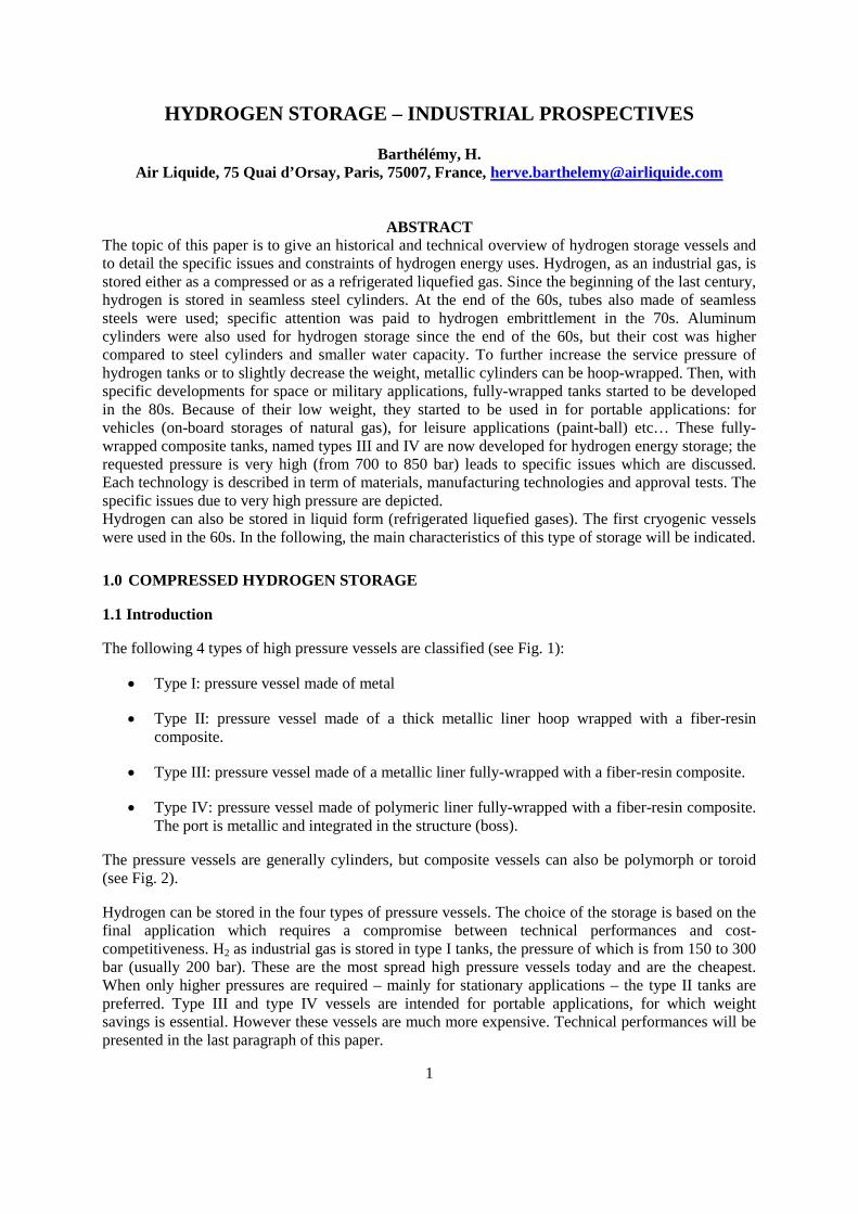
The following 4 types of high pressure vessels are classified (see Fig. 1):
Type I: pressure vessel made of metal
Type II: pressure vessel made of a thick metallic liner hoop wrapped with a fiber-resincomposite.
Type III: pressure vessel made of a metallic liner fully-wrapped with a fiber-resin composite.
Type IV: pressure vessel made of polymeric liner fully-wrapped with a fiber-resin composite.The port is metallic and integrated in the structure (boss).
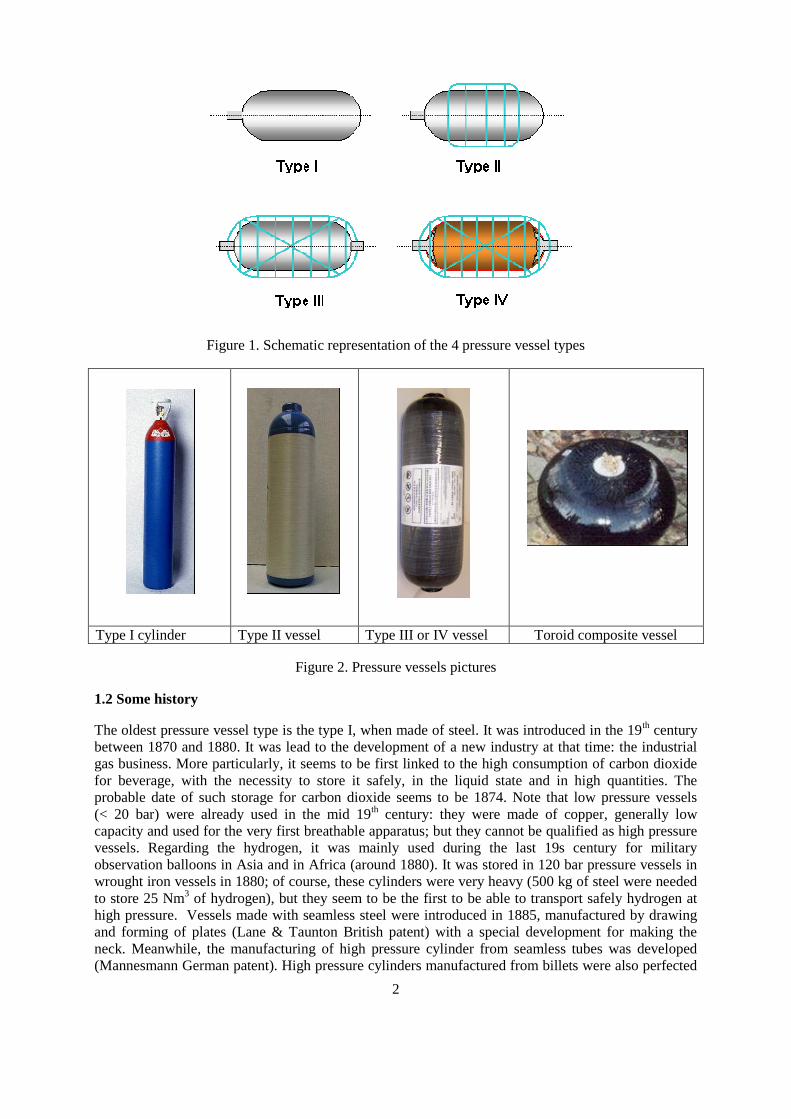
The pressure vessels are generally cylinders, but composite vessels can also be polymorph or toroid(see Fig. 2).
Hydrogen can be stored in the four types of pressure vessels. The choice of the storage is based on thefinal application which requires a compromise between technical performances and cost-competitiveness. H2 as industrial gas is stored in type I tanks, the pressure of which is from 150 to 300bar (usually 200 bar). These are the most spread high pressure vessels today and are the cheapest.When only higher pressures are required – mainly for stationary applications – the type II tanks arepreferred. Type III and type IV vessels are intended for portable applications, for which weightsavings is essential. However these vessels are much more expensive. Technical performances will bepresented in the last paragraph of this paper.
2
Figure 1. Schematic representation of the 4 pressure vessel types
Type I cylinder Type II vessel Type III or IV vessel Toroid composite vessel
Figure 2. Pressure vessels pictures
1.2 Some history
The oldest pressure vessel type is the type I, when made of steel. It was introduced in the 19th centurybetween 1870 and 1880. It was lead to the development of a new industry at that time: the industrialgas business. More particularly, it seems to be first linked to the high consumption of carbon dioxidefor beverage, with the necessity to store it safely, in the liquid state and in high quantities. Theprobable date of such storage for carbon dioxide seems to be 1874. Note that low pressure vessels(< 20 bar) were already used in the mid 19th century: they were made of copper, generally lowcapacity and used for the very first breathable apparatus; but they cannot be qualified as high pressurevessels. Regarding the hydrogen, it was mainly used during the last 19s century for militaryobservation balloons in Asia and in Africa (around 1880). It was stored in 120 bar pressure vessels inwrought iron vessels in 1880; of course, these cylinders were very heavy (500 kg of steel were neededto store 25 Nm3 of hydrogen), but they seem to be the first to be able to transport safely hydrogen athigh pressure. Vessels made with seamless steel were introduced in 1885, manufactured by drawingand forming of plates (Lane & Taunton British patent) with a special development for making theneck. Meanwhile, the manufacturing of high pressure cylinder from seamless tubes was developed(Mannesmann German patent). High pressure cylinders manufactured from billets were also perfected
3
in the late 1880s. Until the 60s, the service pressure of these storages was 150 bar. From 1960, theservice pressure was increased up to 200 bar. Today both 200 and 300 bar cylinders are co-existing forindustrial gases.
High pressure composite vessels were introduced more than 70 years after and were especiallydeveloped for space and military applications, for which technical performances – especially weight –was a very important criteria. The experimentation of composite vessels started in the 50s but the firsthigh pressure vessels used for space and military applications started actually in the 60s in the US(rocket motors and other pressure vessels for space shuttles, sonar equipment etc…). The market ofthese new high pressure vessels was very low in the 60s and the production was not regular at thattime: manufactured batches could count from about ten to a few hundreds vessels (no seriesproduction). They were made of a metallic or polymeric liner wrapped with glass fiber composite. Thecivil market started to be penetrated in the first 70s and was linked to the will to increase the market ofthese high tech products. When compared to the type I conventional vessels for industrial gases, thecost of these composite vessels and the lack of regulation for composite vessels slowed down thispenetration. For example, in the late 70s, 100 000 cycles were requested by the ASME code forpressure vessels – what composites tanks could not fulfill. As a consequence, for each model and eachapplication, the composite vessels had to obtain a special authorization and their lifetime was limited.However, the first important civil market in the 70s was the breathable apparatus for firemen. From80s on, these composite vessels started to be used for skin diving, fuel storage (mainly natural gas) andleisure applications (like paint-ball). The storage pressures were conventional: from 100 to 300 bar.
Many improvements were also performed since the first developments: for example, weight hasdecreased, cycling performance has increased by using thin liners with adequate mechanicalproperties, and other fibers than glass (kevlar, carbon). Moreover the regulation was set up for bothindustrial gases and fuel gas storages.
1.3 Design and manufacturing
For all pressure vessels, the design shall take into account the service and test pressures, the externalstresses which are specific to the use (like impacts, aggressive media, vibrations, temperature ofservice, weight of connectors etc…), the real lifetime (cycling) and the safety coefficients defined forboth static and dynamic conditions. The failure modes like plastic deformation, buckling, creeping,fatigue etc… for metals, delaminations, fiber ruptures, cracks, ageing etc… for composites are alsotaken into account for the design. All these parameters define the mechanical design and the choice ofthe materials. The materials shall also be compatible with the gas when in contact. It is important tonote that metallic vessels and composite vessels are very different:
The metal is isotropic, the composite is anisotropic: the mechanical properties areconcentrated in the fiber direction for the composite.
The failure modes are different.
The ageing is different.
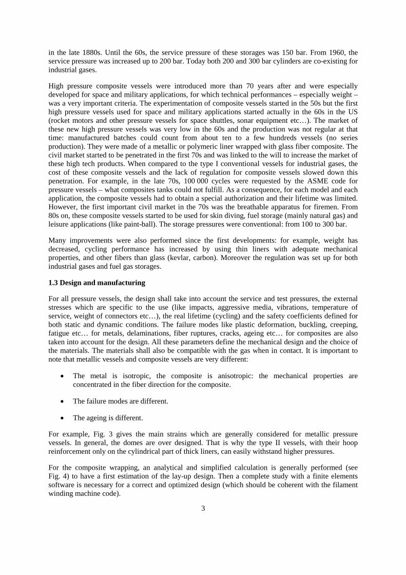
For example, Fig. 3 gives the main strains which are generally considered for metallic pressurevessels. In general, the domes are over designed. That is why the type II vessels, with their hoopreinforcement only on the cylindrical part of thick liners, can easily withstand higher pressures.
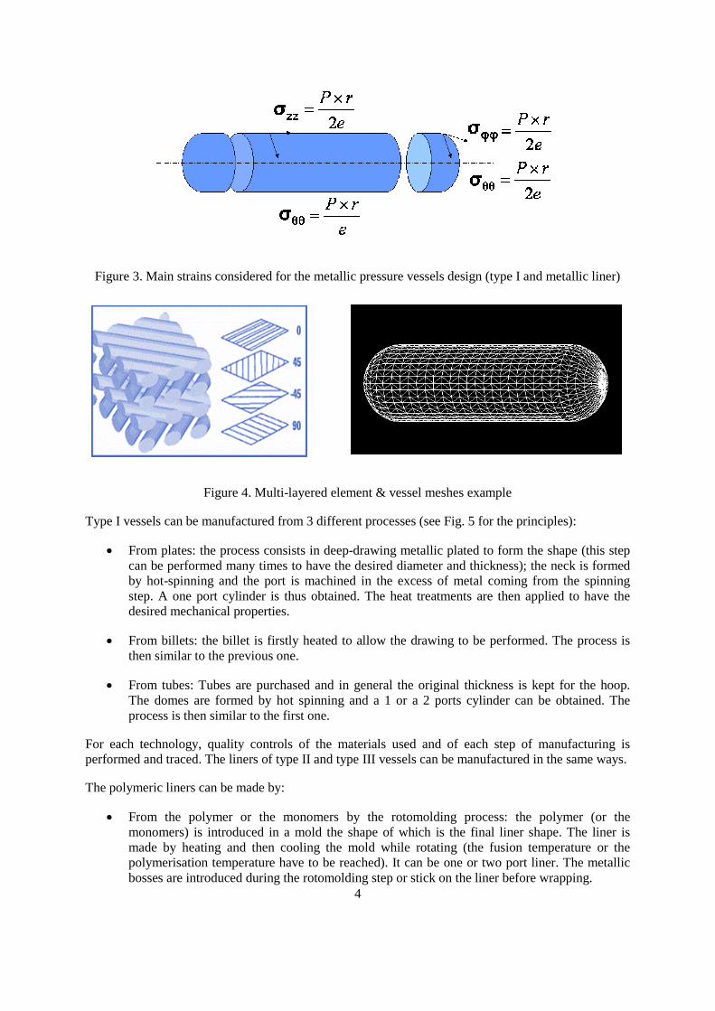
For the composite wrapping, an analytical and simplified calculation is generally performed (seeFig. 4) to have a first estimation of the lay-up design. Then a complete study with a finite elementssoftware is necessary for a correct and optimized design (which should be coherent with the filamentwinding machine code).
4
Figure 3. Main strains considered for the metallic pressure vessels design (type I and metallic liner)
Figure 4. Multi-layered element & vessel meshes example
Type I vessels can be manufactured from 3 different processes (see Fig. 5 for the principles):
From plates: the process consists in deep-drawing metallic plated to form the shape (this stepcan be performed many times to have the desired diameter and thickness); the neck is formedby hot-spinning and the port is machined in the excess of metal coming from the spinningstep. A one port cylinder is thus obtained. The heat treatments are then applied to have thedesired mechanical properties.
From billets: the billet is firstly heated to allow the drawing to be performed. The process isthen similar to the previous one.
From tubes: Tubes are purchased and in general the original thickness is kept for the hoop.The domes are formed by hot spinning and a 1 or a 2 ports cylinder can be obtained. Theprocess is then similar to the first one.
For each technology, quality controls of the materials used and of each step of manufacturing isperformed and traced. The liners of type II and type III vessels can be manufactured in the same ways.
The polymeric liners can be made by:
From the polymer or the monomers by the rotomolding process: the polymer (or themonomers) is introduced in a mold the shape of which is the final liner shape. The liner ismade by heating and then cooling the mold while rotating (the fusion temperature or thepolymerisation temperature have to be reached). It can be one or two port liner. The metallicbosses are introduced during the rotomolding step or stick on the liner before wrapping.
5
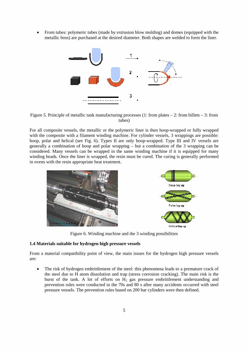
From tubes: polymeric tubes (made by extrusion blow molding) and domes (equipped with themetallic boss) are purchased at the desired diameter. Both shapes are welded to form the liner.
Figure 5. Principle of metallic tank manufacturing processes (1: from plates – 2: from billets – 3: fromtubes)
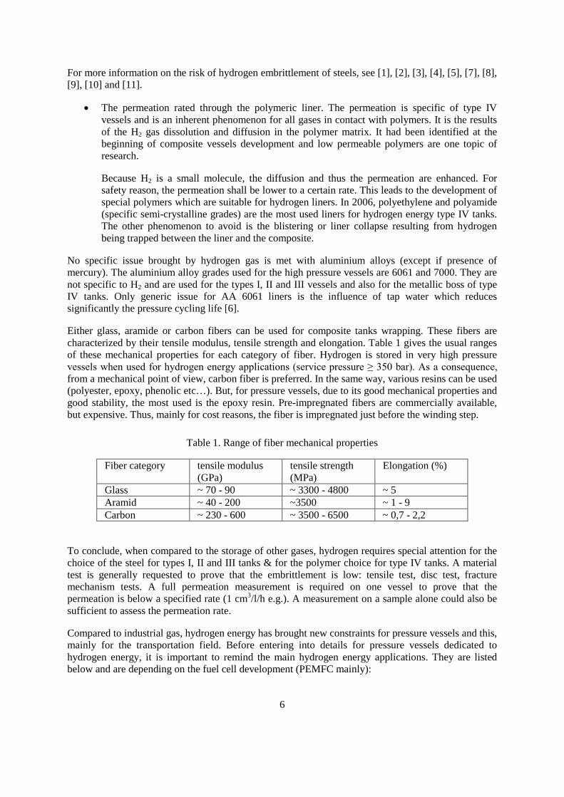
For all composite vessels, the metallic or the polymeric liner is then hoop-wrapped or fully wrappedwith the composite with a filament winding machine. For cylinder vessels, 3 wrappings are possible:hoop, polar and helical (see Fig. 6). Types II are only hoop-wrapped. Type III and IV vessels aregenerally a combination of hoop and polar wrapping – but a combination of the 3 wrapping can beconsidered. Many vessels can be wrapped in the same winding machine if it is equipped for manywinding heads. Once the liner is wrapped, the resin must be cured. The curing is generally performedin ovens with the resin appropriate heat treatment.
Figure 6. Winding machine and the 3 winding possibilities
1.4 Materials suitable for hydrogen high pressure vessels
From a material compatibility point of view, the main issues for the hydrogen high pressure vesselsare:
The risk of hydrogen embrittlement of the steel: this phenomena leads to a premature crack ofthe steel due to H atom dissolution and trap (stress corrosion cracking). The main risk is theburst of the tank. A lot of efforts on H2 gas pressure embrittlement understanding andprevention rules were conducted in the 70s and 80 s after many accidents occurred with steelpressure vessels. The prevention rules based on 200 bar cylinders were then defined.
CNRS-LMARC-
6
For more information on the risk of hydrogen embrittlement of steels, see [1], [2], [3], [4], [5], [7], [8],[9], [10] and [11].
The permeation rated through the polymeric liner. The permeation is specific of type IVvessels and is an inherent phenomenon for all gases in contact with polymers. It is the resultsof the H2 gas dissolution and diffusion in the polymer matrix. It had been identified at thebeginning of composite vessels development and low permeable polymers are one topic ofresearch.
Because H2 is a small molecule, the diffusion and thus the permeation are enhanced. Forsafety reason, the permeation shall be lower to a certain rate. This leads to the development ofspecial polymers which are suitable for hydrogen liners. In 2006, polyethylene and polyamide(specific semi-crystalline grades) are the most used liners for hydrogen energy type IV tanks.The other phenomenon to avoid is the blistering or liner collapse resulting from hydrogenbeing trapped between the liner and the composite.
No specific issue brought by hydrogen gas is met with aluminium alloys (except if presence ofmercury). The aluminium alloy grades used for the high pressure vessels are 6061 and 7000. They arenot specific to H2 and are used for the types I, II and III vessels and also for the metallic boss of typeIV tanks. Only generic issue for AA 6061 liners is the influence of tap water which reducessignificantly the pressure cycling life [6].
Either glass, aramide or carbon fibers can be used for composite tanks wrapping. These fibers arecharacterized by their tensile modulus, tensile strength and elongation. Table 1 gives the usual rangesof these mechanical properties for each category of fiber. Hydrogen is stored in very high pressurevessels when used for hydrogen energy applications (service pressure ≥ 350 bar). As a consequence, from a mechanical point of view, carbon fiber is preferred. In the same way, various resins can be used(polyester, epoxy, phenolic etc…). But, for pressure vessels, due to its good mechanical properties andgood stability, the most used is the epoxy resin. Pre-impregnated fibers are commercially available,but expensive. Thus, mainly for cost reasons, the fiber is impregnated just before the winding step.
Table 1. Range of fiber mechanical properties
Fiber category tensile modulus(GPa)
tensile strength(MPa)
Elongation (%)
Glass ~ 70 - 90 ~ 3300 - 4800 ~ 5Aramid ~ 40 - 200 ~3500 ~ 1 - 9Carbon ~ 230 - 600 ~ 3500 - 6500 ~ 0,7 - 2,2
To conclude, when compared to the storage of other gases, hydrogen requires special attention for thechoice of the steel for types I, II and III tanks & for the polymer choice for type IV tanks. A materialtest is generally requested to prove that the embrittlement is low: tensile test, disc test, fracturemechanism tests. A full permeation measurement is required on one vessel to prove that thepermeation is below a specified rate (1 cm3/l/h e.g.). A measurement on a sample alone could also besufficient to assess the permeation rate.
Compared to industrial gas, hydrogen energy has brought new constraints for pressure vessels and this,mainly for the transportation field. Before entering into details for pressure vessels dedicated tohydrogen energy, it is important to remind the main hydrogen energy applications. They are listedbelow and are depending on the fuel cell development (PEMFC mainly):
7
Fuel for transportation: buses, car, scooters, other leisure vehicles. These vehicles can bepowered by a fuel cell or by an internal combustion engine fuelled with H2. Use in boats isalso considered. For this application, the main constraint at the moment is the weight andvolume savings. As a consequence for the pressure storage, types III and IV could beconsidered but the cost of the storage system is also important. This is why type I or II is used.
Stationary applications: back-up power supply or power generator for residential. For thisapplication, the cost of hydrogen supplied is the main parameter. The pressure cycle life isalso an issue.
Portable applications: portable back-up power supply, portable power generators, electronics(computers, mobile phones, etc…).
Weight and volume savings are primordial. The performances which are generally used to comparethe pressure vessels are Cm and Cv defined as:
Cm: weight performance: mass of H2 stored divided by the mass of the vessel (%wt)
Cv: volume performance: mass of H2 stored divided by the external volume of the vessel (g/l)
cost
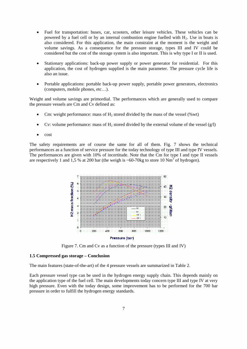
The safety requirements are of course the same for all of them. Fig. 7 shows the technicalperformances as a function of service pressure for the today technology of type III and type IV vessels.The performances are given with 10% of incertitude. Note that the Cm for type I and type II vesselsare respectively 1 and 1,5 % at 200 bar (the weigh is ~60-70kg to store 10 Nm3 of hydrogen).
Figure 7. Cm and Cv as a function of the pressure (types III and IV)
1.5 Compressed gas storage – Conclusion
The main features (state-of-the-art) of the 4 pressure vessels are summarized in Table 2.
Each pressure vessel type can be used in the hydrogen energy supply chain. This depends mainly onthe application type of the fuel cell. The main developments today concern type III and type IV at veryhigh pressure. Even with the today design, some improvement has to be performed for the 700 barpressure in order to fulfill the hydrogen energy standards.
8
Table 2. Main features for H2 pressure vessel types in 2006
Type I Type II Type III Type IVTechnology mature: ++Pressure limited to 300bar ( density: )Cost performance: ++Weight performance:
Technology mature: +Pressure not limited( density: +)Cost performance: +Weight performance: 0
Technology mature forP ≤ 350 bar; 700 bar under development.Cost performance: Weight performance: +
Technology mature forP ≤ 350 bar; 700 bar under development.Cost performance: Weight performance: +
2.0 CRYOGENIC VESSELS FOR THE STORAGE OF LIQUID HYDROGEN
2.1 Introduction (comparison of efficiency/grows storage)
Cryogenic vessels have been commonly used for more than 40 years for the storage and transportationof industrial and medical gases. The advantage of storing gases in such form is obvious: in a volumeof 1 litre of liquid, about 800 litres of gas can be stored. This represents a clear advantage compared tothe transportation of such gases in compressed form, which is done today at pressures of 200-300 bar(less gas per volume unit) and require thick walls (and heavy vessels) to resist the high pressure.
The disadvantage is, of course, that the gases need to be refrigerated down to very low temperatures tobe in liquid form, especially for liquid hydrogen. The temperature gas/liquid equilibrium for differentgases under a pressure of one atmosphere are given in Table 3. For gases being stored at such lowtemperatures, it is necessary to use high efficiency (vacuum) insulated vessels.
Table 3. Boiling temperatures at atmospheric pressure of different gases
Gases Kr O2 Ar Air N2 Ne H2 HeBoilingtemperature
- 153 - 183 - 186 - 191 - 196 - 246 - 253 - 269
2.2 Different types of cryogenic vessels
Cryogenic vessels can be differentiated either by the type of insulation used or the type ofapplications.
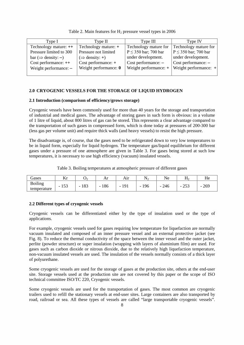
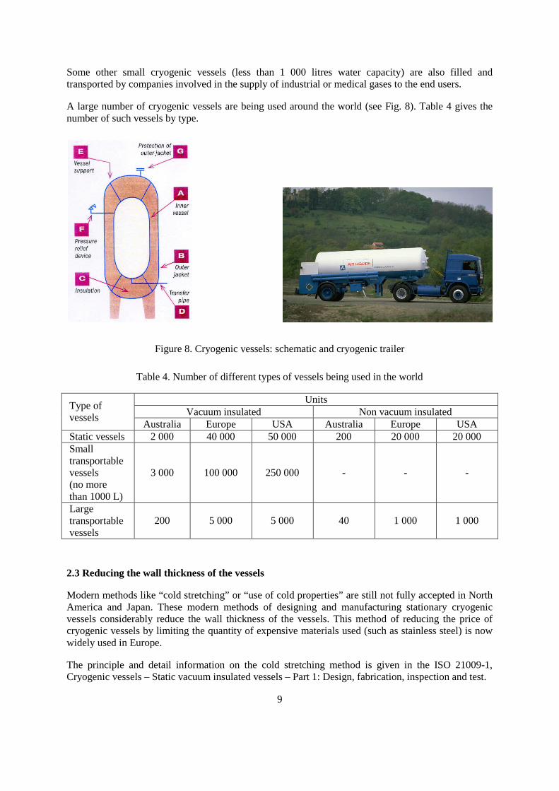
For example, cryogenic vessels used for gases requiring low temperature for liquefaction are normallyvacuum insulated and composed of an inner pressure vessel and an external protective jacket (seeFig. 8). To reduce the thermal conductivity of the space between the inner vessel and the outer jacket,perlite (powder structure) or super insulation (wrapping with layers of aluminium film) are used. Forgases such as carbon dioxide or nitrous dioxide, due to the relatively high liquefaction temperature,non-vacuum insulated vessels are used. The insulation of the vessels normally consists of a thick layerof polyurethane.
Some cryogenic vessels are used for the storage of gases at the production site, others at the end-usersite. Storage vessels used at the production site are not covered by this paper or the scope of ISOtechnical committee ISO/TC 220, Cryogenic vessels.
Some cryogenic vessels are used for the transportation of gases. The most common are cryogenictrailers used to refill the stationary vessels at end-user sites. Large containers are also transported byroad, railroad or sea. All these types of vessels are called “large transportable cryogenic vessels”.
9
Some other small cryogenic vessels (less than 1 000 litres water capacity) are also filled andtransported by companies involved in the supply of industrial or medical gases to the end users.
A large number of cryogenic vessels are being used around the world (see Fig. 8). Table 4 gives thenumber of such vessels by type.
Figure 8. Cryogenic vessels: schematic and cryogenic trailer
Table 4. Number of different types of vessels being used in the world
UnitsVacuum insulated Non vacuum insulated
Type ofvessels
Australia Europe USA Australia Europe USAStatic vessels 2 000 40 000 50 000 200 20 000 20 000Smalltransportablevessels(no morethan 1000 L)
3 000 100 000 250 000 - - -
Largetransportablevessels
200 5 000 5 000 40 1 000 1 000
2.3 Reducing the wall thickness of the vessels
Modern methods like “cold stretching” or “use of cold properties” are still not fully accepted in NorthAmerica and Japan. These modern methods of designing and manufacturing stationary cryogenicvessels considerably reduce the wall thickness of the vessels. This method of reducing the price ofcryogenic vessels by limiting the quantity of expensive materials used (such as stainless steel) is nowwidely used in Europe.
The principle and detail information on the cold stretching method is given in the ISO 21009-1,Cryogenic vessels – Static vacuum insulated vessels – Part 1: Design, fabrication, inspection and test.
10
However, all efforts were made to produce efficient ISO standards for stationary cryogenic vessels inan expedient manner. ISO 21009-2, Cryogenic vessels – Static vacuum insulated vessels – Part 2:Operational requirements, is already available, while ISO 21009-1, Cryogenic vessels – Staticvacuum-insulated vessels completed and waiting to be issued in the coming months.
2.4 Transport of liquid hydrogen
In order to reduce the volume required to store a useful amount of hydrogen –particularly for vehicles-liquefaction may be employed. Since hydrogen does not liquefy until it reaches -253° C (20 degreesabove absolute zero), the process is both time consuming and energy intensive demanding. Up to 40%of the energy content in the hydrogen can be lost (in comparison with 10% energy loss withcompressed hydrogen). The advantage of liquid hydrogen is its high energy/mass ratio, three timesthat of gasoline. It is the most energy dense fuel in use (excluding nuclear reactions fuels), which iswhy it is employed in all space programmes. However, energy/volume ratio remains low compared togasoline. Liquid hydrogen is difficult to store over a long period (product loss by vaporisation), andthe insulated tank required may be large and bulky.
Liquid hydrogen road transport is carried out using trucks which can exceed a capacity of 60 000litres. Delivery is achieved either in vacuum insulated containers or by transferring the product tostationary vessels depending on the required quantities.
In the USA there are several pipelines for liquid hydrogen with lengths of up to 40 km.
The intercontinental transport of hydrogen will probably be carried out in liquid form using ships. Forthis purpose, specialized ships with appropriate tanks and port facilities are being designed. Arealization of these ideas will however not take place until the trade in hydrogen reaches anappropriately large scale.
2.5 Material issues
Hydrogen embrittlement (HE)
When the gas is at room temperature, the requirement of section 1.4 applies. For the liquid at lowtemperature, the specific considerations are:
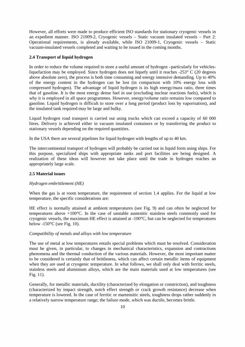
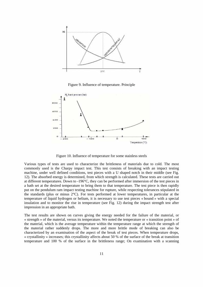
HE effect is normally attained at ambient temperatures (see Fig. 9) and can often be neglected fortemperatures above +100°C. In the case of unstable austenitic stainless steels commonly used forcryogenic vessels, the maximum HE effect is attained at -100°C, but can be neglected for temperaturesbelow -150°C (see Fig. 10).
Compatibility of metals and alloys with low temperature
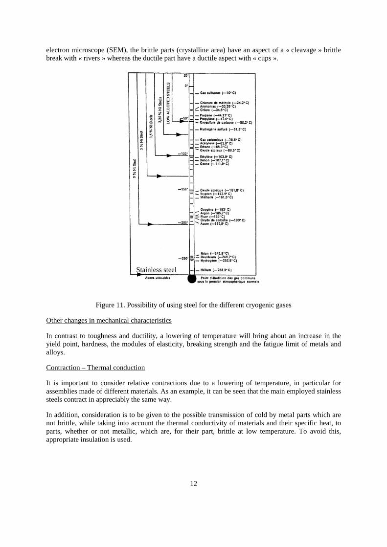
The use of metal at low temperatures entails special problems which must be resolved. Considerationmust be given, in particular, to changes in mechanical characteristics, expansion and contractionsphenomena and the thermal conduction of the various materials. However, the most important matterto be considered is certainly that of brittleness, which can affect certain metallic items of equipmentwhen they are used at cryogenic temperature. In what follows, we shall only deal with ferritic steels,stainless steels and aluminium alloys, which are the main materials used at low temperatures (seeFig. 11).
Generally, for metallic materials, ductility (characterized by elongation or constriction), and toughness(characterized by impact strength, notch effect strength or crack growth resistance) decrease whentemperature is lowered. In the case of ferritic or martensitic steels, toughness drops rather suddenly ina relatively narrow temperature range; the failure mode, which was ductile, becomes brittle.
11
Figure 9. Influence of temperature. Principle
Figure 10. Influence of temperature for some stainless steels
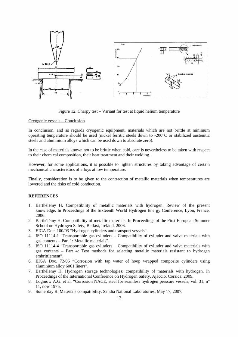
Various types of tests are used to characterize the brittleness of materials due to cold. The mostcommonly used is the Charpy impact test. This test consists of breaking with an impact testingmachine, under well defined conditions, test pieces with a U shaped notch in their middle (see Fig.12). The absorbed energy is determined, from which strength is calculated. These tests are carried outat different temperatures. Down to -196°C, they can be performed after immersion of the test pieces ina bath set at the desired temperature to bring them to that temperature. The test piece is then rapidlyput on the pendulum ram impact testing machine for rupture, while respecting tolerances stipulated inthe standards (plus or minus 2°C). For tests performed at lower temperatures, in particular at thetemperature of liquid hydrogen or helium, it is necessary to use test pieces « bound » with a specialinsulation and to monitor the rise in temperature (see Fig. 12) during the impact strength test afterimpression in an appropriate bath.
The test results are shown on curves giving the energy needed for the failure of the material, or« strength » of the material, versus its temperature. We noted the temperature or « transition point » ofthe material, which is the average temperature within the temperature range at which the strength ofthe material rather suddenly drops. The more and more brittle mode of breaking can also becharacterized by an examination of the aspect of the break of test pieces. When temperature drops,« crystallinity » increases; this crystallinity affects about 50 % of the surface of the break at transitiontemperature and 100 % of the surface in the brittleness range; On examination with a scanning
electron microscope (SEM), the brittle parts (crystalline area) have an aspect of a « cleavage » brittlebreak with « rivers » whereas the ductile part have a ductile aspect with « cups ».
Figure 11. Po
Other changes in mechanical c
In contrast to toughness andyield point, hardness, the modalloys.
Contraction – Thermal conduc
It is important to consider reassemblies made of different msteels contract in appreciably t
In addition, consideration is tonot brittle, while taking into aparts, whether or not metalliappropriate insulation is used.
Stainless steel
12
ssibility of using steel for the different cryogenic gases
haracteristics
ductility, a lowering of temperature will bring about an increase in theules of elasticity, breaking strength and the fatigue limit of metals and
tion
lative contractions due to a lowering of temperature, in particular foraterials. As an example, it can be seen that the main employed stainless
he same way.
be given to the possible transmission of cold by metal parts which areccount the thermal conductivity of materials and their specific heat, to
c, which are, for their part, brittle at low temperature. To avoid this,
13
Figure 12. Charpy test – Variant for test at liquid helium temperature
Cryogenic vessels – Conclusion
In conclusion, and as regards cryogenic equipment, materials which are not brittle at minimumoperating temperature should be used (nickel ferritic steels down to -200°C or stabilized austeniticsteels and aluminium alloys which can be used down to absolute zero).
In the case of materials known not to be brittle when cold, care is nevertheless to be taken with respectto their chemical composition, their heat treatment and their welding.
However, for some applications, it is possible to lighten structures by taking advantage of certainmechanical characteristics of alloys at low temperature.
Finally, consideration is to be given to the contraction of metallic materials when temperatures arelowered and the risks of cold conduction.
REFERENCES
1. Barthélémy H. Compatibility of metallic materials with hydrogen. Review of the presentknowledge. In Proceedings of the Sixteenth World Hydrogen Energy Conference, Lyon, France,2006.
2. Barthélémy H. Compatibility of metallic materials. In Proceedings of the First European SummerSchool on Hydrogen Safety, Belfast, Ireland, 2006.
3. EIGA Doc. 100/03 “Hydrogen cylinders and transport vessels”.4. ISO 11114-1 “Transportable gas cylinders – Compatibility of cylinder and valve materials with
gas contents – Part 1: Metallic materials”.5. ISO 11114-4 “Transportable gas cylinders – Compatibility of cylinder and valve materials with
gas contents – Part 4: Test methods for selecting metallic materials resistant to hydrogenembrittlement”.
6. EIGA Doc. 72/06 “Corrosion with tap water of hoop wrapped composite cylinders usingaluminium alloy 6061 liners”.
7. Barthélémy H. Hydrogen storage technologies: compatibility of materials with hydrogen. InProceedings of the International Conference on Hydrogen Safety, Ajaccio, Corsica, 2009.
8. Loginow A.G. et al. “Corrosion NACE, steel for seamless hydrogen pressure vessels, vol. 31, n°11, now 1975.
9. Somerday B. Materials compatibility, Sandia National Laboratories, May 17, 2007.

14
10. Pressouyre G. Current solutions to hydrogen problems in steel, ed. by C.G. Interrante and G.M.Pressouyre. Proceedings of the First International Conference on current solutions to hydrogenproblems in steels, November 1, 1982, pp. 18-31.
11. Moody N.R., Robinson S.L. and Somerday B.P., Hydrogen embrittlement of stainless steels,Sandia National Laboratories, Livermore, CA.