Embed Size (px)
Citation preview
GA
GD
GBB
GBE
GBC
GBF
GBP
GBQ
GN
Hydraulic Unit
CP
CR
CPB
CPD
CPC
CPE
CQC
CQE
Pump Unit
CB
CD
CC
Valve Unit
BC
BH
MV
Operational Control Panel
YP
YA
Clamp
ClampHydraulic UnitOperation Control Panel
Die LifterPre-Roller
Accessories
CautionsCompany Profile
ActionDescription
System StructureExample
Model No.Indication Specifications External
DimensionsCautionsP.067
Clamp HookModel GAH
Air
Hydraulic Unit
Model GA
Single-action cyl inder with compact s ize.Space eff ic ient for mounting.
Hydraulic Piston Clamp
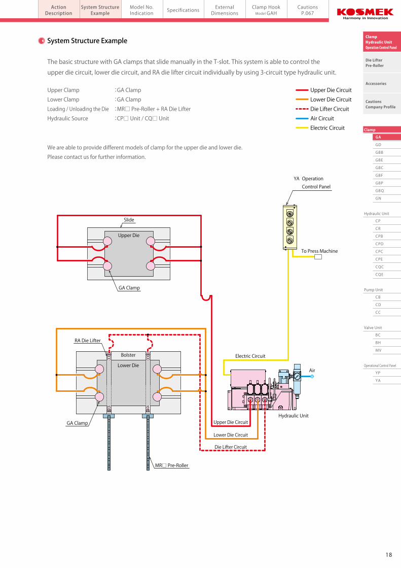
System Structure Example
T-Slot Manual-Slide
Upper Die
Electric Circuit
Upper Die Circuit
Lower Die Circuit
Die Lifter Circuit
Lower Die
Bolster
Slide
RA Die Lifter
GA Clamp
GA Clamp
MR□ Pre-Roller
The basic structure with GA clamps that slide manually in the T-slot. This system is able to control the
upper die circuit, lower die circuit, and RA die lifter circuit individually by using 3-circuit type hydraulic unit.
Upper Clamp :GA Clamp
Lower Clamp :GA Clamp
Loading / Unloading the Die :MR□ Pre-Roller + RA Die Lifter
Hydraulic Source :CP□ Unit / CQ□ Unit
We are able to provide different models of clamp for the upper die and lower die.
Please contact us for further information.
Upper Die Circuit
Lower Die Circuit
Die Lifter Circuit
Air Circuit
Electric Circuit
To Press Machine
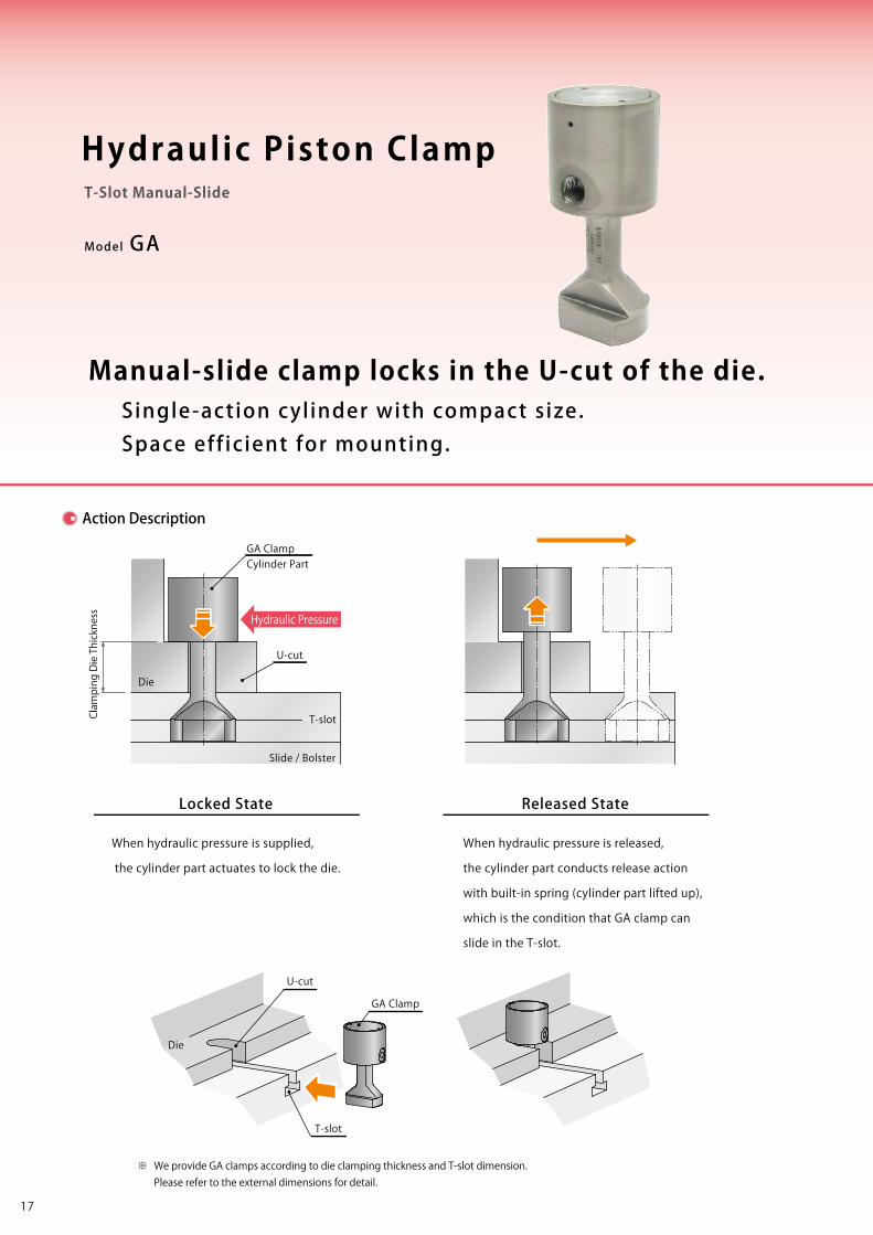
Manual-slide clamp locks in the U-cut of the die.
Action Description
※ We provide GA clamps according to die clamping thickness and T-slot dimension. Please refer to the external dimensions for detail.
Hydraulic Pressure
Locked State
When hydraulic pressure is supplied,
the cylinder part actuates to lock the die.
Released State
When hydraulic pressure is released,
the cylinder part conducts release action
with built-in spring (cylinder part lifted up),
which is the condition that GA clamp can
slide in the T-slot.
Die
Clamping Die Thickness
Die
U-cut
Slide / Bolster
T-slot
U-cut
T-slot
GA Clamp
GA ClampCylinder Part
YA Operation
Control Panel
1817
GA
GD
GBB
GBE
GBC
GBF
GBP
GBQ
GN
Hydraulic Unit
CP
CR
CPB
CPD
CPC
CPE
CQC
CQE
Pump Unit
CB
CD
CC
Valve Unit
BC
BH
MV
Operational Control Panel
YP
YA
Clamp
ClampHydraulic UnitOperation Control Panel
Die LifterPre-Roller
Accessories
CautionsCompany Profile
ActionDescription
System StructureExample
Model No.Indication Specifications External
DimensionsCautionsP.067
Clamp HookModel GAH
Air
Hydraulic Unit
Model GA
Single-action cyl inder with compact s ize.Space eff ic ient for mounting.
Hydraulic Piston Clamp
System Structure Example
T-Slot Manual-Slide
Upper Die
Electric Circuit
Upper Die Circuit
Lower Die Circuit
Die Lifter Circuit
Lower Die
Bolster
Slide
RA Die Lifter
GA Clamp
GA Clamp
MR□ Pre-Roller
The basic structure with GA clamps that slide manually in the T-slot. This system is able to control the
upper die circuit, lower die circuit, and RA die lifter circuit individually by using 3-circuit type hydraulic unit.
Upper Clamp :GA Clamp
Lower Clamp :GA Clamp
Loading / Unloading the Die :MR□ Pre-Roller + RA Die Lifter
Hydraulic Source :CP□ Unit / CQ□ Unit
We are able to provide different models of clamp for the upper die and lower die.
Please contact us for further information.
Upper Die Circuit
Lower Die Circuit
Die Lifter Circuit
Air Circuit
Electric Circuit
To Press Machine
Manual-slide clamp locks in the U-cut of the die.
Action Description
※ We provide GA clamps according to die clamping thickness and T-slot dimension. Please refer to the external dimensions for detail.
Hydraulic Pressure
Locked State
When hydraulic pressure is supplied,
the cylinder part actuates to lock the die.
Released State
When hydraulic pressure is released,
the cylinder part conducts release action
with built-in spring (cylinder part lifted up),
which is the condition that GA clamp can
slide in the T-slot.
Die
Clamping Die Thickness
Die
U-cut
Slide / Bolster
T-slot
U-cut
T-slot
GA Clamp
GA ClampCylinder Part
YA Operation
Control Panel
1817
GA
GD
GBB
GBE
GBC
GBF
GBP
GBQ
GN
Hydraulic Unit
CP
CR
CPB
CPD
CPC
CPE
CQC
CQE
Pump Unit
CB
CD
CC
Valve Unit
BC
BH
MV
Operational Control Panel
YP
YA
Clamp
ClampHydraulic UnitOperation Control Panel
Die LifterPre-Roller
Accessories
CautionsCompany Profile
ActionDescription
System StructureExample
Model No.Indication Specifications External
DimensionsCautionsP.067
Clamp HookModel GAHmodel GAHydraulic Piston Clamp T-slot Manual-Slide
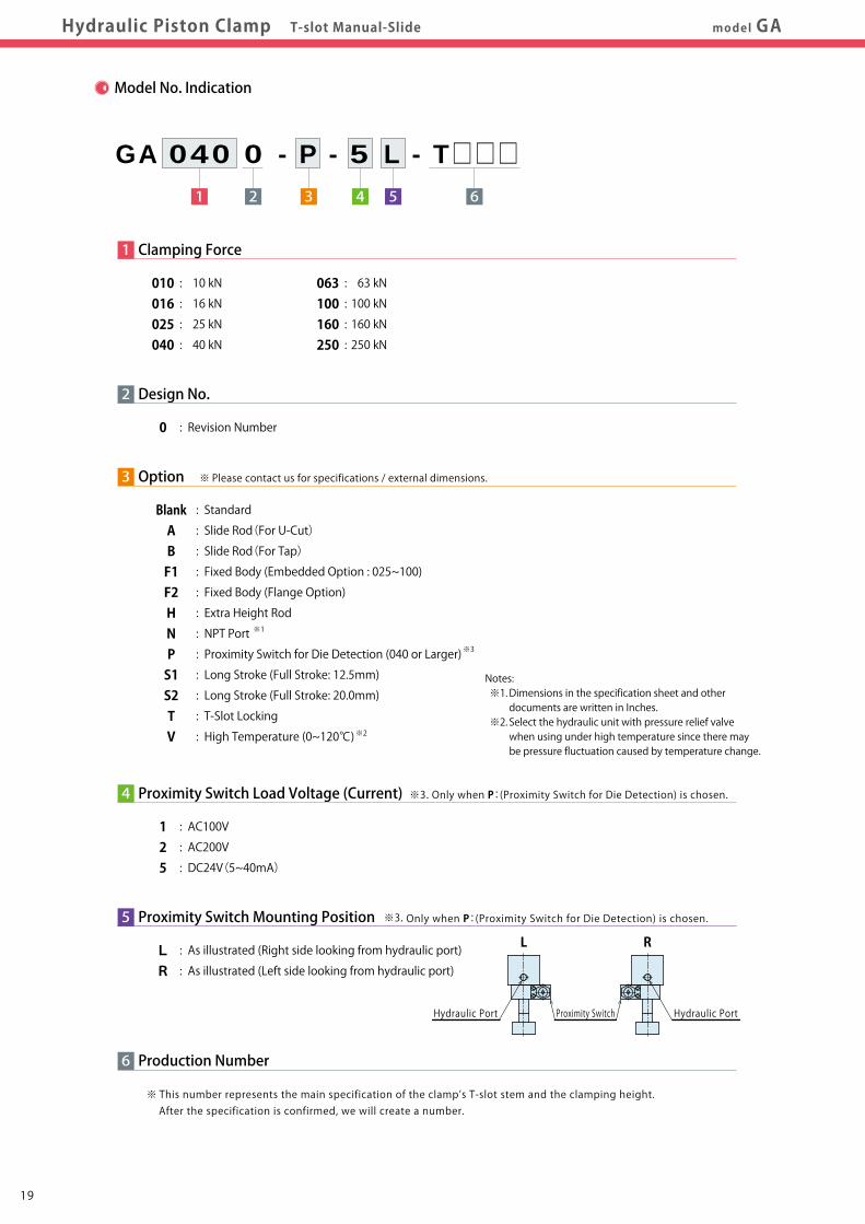
Model No. Indication
1 3 4 5 62
GA 040 0 - P - 5 L - T□□□
2 Design No.
0 : Revision Number
1 Clamping Force
010 : 10 kN 016 : 16 kN 025 : 25 kN 040 : 40 kN
063 : 63 kN 100 : 100 kN 160 : 160 kN 250 : 250 kN
3 Option
Blank : Standard A : Slide Rod(For U-Cut)
B : Slide Rod(For Tap)
F1 : Fixed Body (Embedded Option : 025~100) F2 : Fixed Body (Flange Option) H : Extra Height Rod
N : NPT Port
P : Proximity Switch for Die Detection (040 or Larger)
S1 : Long Stroke (Full Stroke: 12.5mm) S2 : Long Stroke (Full Stroke: 20.0mm) T : T-Slot Locking
V : High Temperature (0~120℃)
4 Proximity Switch Load Voltage (Current)
1 : AC100V 2 : AC200V 5 : DC24V(5~40mA)
5 Proximity Switch Mounting Position
L : As illustrated (Right side looking from hydraulic port) R : As illustrated (Left side looking from hydraulic port)
6 Production Number
※ This number represents the main specification of the clamp’s T-slot stem and the clamping height. After the specification is confirmed, we will create a number.
Model No.
Clamping Force kN
Working Pressure MPa
Withstanding Pressure MPa
Full Stroke mm
Clamp Stroke mm
Extra Stroke mm
Cylinder Capacity (At Full Stroke) cm3
Operating Temperature ※4 ℃
Use Frequency ※5
Pressurizing Agent ※6 ※7 ※8
Min. T-slot Width a (JIS) ※9 mm
Max. T-slot Width a (JIS) ※9 mm
GA0100 GA0160 GA0250 GA0400 GA0630 GA1000 GA1600 GA2500
10 16 25 40 63 100 160 250
25 (For Rated Clamp Force)
37
6 8 8 8 8 8 8 8
4 5 5 5 5 5 5 5
2 3 3 3 3 3 3 3
2.5 5.7 8 13 21 31 54 76
0 ~ 70 (V : High temperature type is available for 0 ~ 120℃)
20 Cycles / Day or less
ISO-VG-32 or Equivalent
8 10 12 16 18 22 28 36
20 24 32 42 42 54 54 54
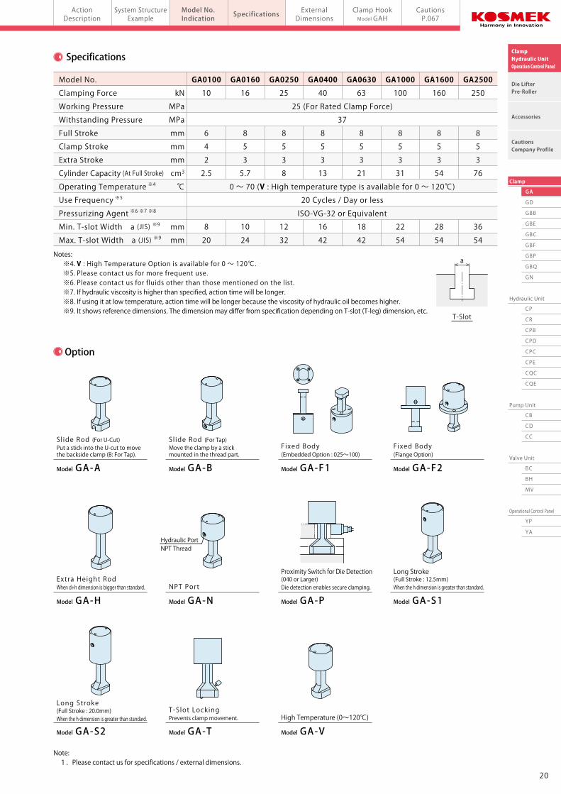
Specifications
※ Please contact us for specifications / external dimensions.
※3.Only when P:(Proximity Switch for Die Detection) is chosen.
※3.Only when P:(Proximity Switch for Die Detection) is chosen.
Hydraulic PortNPT Thread
a
T-Slot
L R
Proximity SwitchHydraulic Port Hydraulic Port
Option
Notes: ※4. V : High Temperature Option is available for 0 ~ 120℃. ※5. Please contact us for more frequent use. ※6. Please contact us for fluids other than those mentioned on the list. ※7. If hydraulic viscosity is higher than specified, action time will be longer. ※8. If using it at low temperature, action time will be longer because the viscosity of hydraulic oil becomes higher. ※9. It shows reference dimensions. The dimension may differ from specification depending on T-slot (T-leg) dimension, etc.
Model GA-VHigh Temperature (0~120℃)
Model GA-TPrevents clamp movement.T-Slot Locking
Model GA-S2
(Full Stroke : 20.0mm)When the h dimension is greater than standard.
Long Stroke
Model GA-S1
Long Stroke(Full Stroke : 12.5mm)When the h dimension is greater than standard.
Model GA-P
(040 or Larger)Die detection enables secure clamping.
Proximity Switch for Die Detection
Model GA-NNPT Port
Model GA-HWhen d+h dimension is bigger than standard.Extra Height Rod
Model GA-F2(Flange Option)Fixed Body
Model GA-F1(Embedded Option : 025~100)Fixed Body
Model GA-B
Move the clamp by a stickmounted in the thread part.
S l ide Rod (For Tap)
Model GA-A
Put a stick into the U-cut to movethe backside clamp (B: For Tap).
S l ide Rod (For U-Cut)
Note: 1. Please contact us for specifications / external dimensions.
Notes: ※1. Dimensions in the specification sheet and other documents are written in Inches. ※2. Select the hydraulic unit with pressure relief valve when using under high temperature since there may be pressure fluctuation caused by temperature change.
※3
※2
※1
2019
GA
GD
GBB
GBE
GBC
GBF
GBP
GBQ
GN
Hydraulic Unit
CP
CR
CPB
CPD
CPC
CPE
CQC
CQE
Pump Unit
CB
CD
CC
Valve Unit
BC
BH
MV
Operational Control Panel
YP
YA
Clamp
ClampHydraulic UnitOperation Control Panel
Die LifterPre-Roller
Accessories
CautionsCompany Profile
ActionDescription
System StructureExample
Model No.Indication Specifications External
DimensionsCautionsP.067
Clamp HookModel GAHmodel GAHydraulic Piston Clamp T-slot Manual-Slide
Model No. Indication
1 3 4 5 62
GA 040 0 - P - 5 L - T□□□
2 Design No.
0 : Revision Number
1 Clamping Force
010 : 10 kN 016 : 16 kN 025 : 25 kN 040 : 40 kN
063 : 63 kN 100 : 100 kN 160 : 160 kN 250 : 250 kN
3 Option
Blank : Standard A : Slide Rod(For U-Cut)
B : Slide Rod(For Tap)
F1 : Fixed Body (Embedded Option : 025~100) F2 : Fixed Body (Flange Option) H : Extra Height Rod
N : NPT Port
P : Proximity Switch for Die Detection (040 or Larger)
S1 : Long Stroke (Full Stroke: 12.5mm) S2 : Long Stroke (Full Stroke: 20.0mm) T : T-Slot Locking
V : High Temperature (0~120℃)
4 Proximity Switch Load Voltage (Current)
1 : AC100V 2 : AC200V 5 : DC24V(5~40mA)
5 Proximity Switch Mounting Position
L : As illustrated (Right side looking from hydraulic port) R : As illustrated (Left side looking from hydraulic port)
6 Production Number
※ This number represents the main specification of the clamp’s T-slot stem and the clamping height. After the specification is confirmed, we will create a number.
Model No.
Clamping Force kN
Working Pressure MPa
Withstanding Pressure MPa
Full Stroke mm
Clamp Stroke mm
Extra Stroke mm
Cylinder Capacity (At Full Stroke) cm3
Operating Temperature ※4 ℃
Use Frequency ※5
Pressurizing Agent ※6 ※7 ※8
Min. T-slot Width a (JIS) ※9 mm
Max. T-slot Width a (JIS) ※9 mm
GA0100 GA0160 GA0250 GA0400 GA0630 GA1000 GA1600 GA2500
10 16 25 40 63 100 160 250
25 (For Rated Clamp Force)
37
6 8 8 8 8 8 8 8
4 5 5 5 5 5 5 5
2 3 3 3 3 3 3 3
2.5 5.7 8 13 21 31 54 76
0 ~ 70 (V : High temperature type is available for 0 ~ 120℃)
20 Cycles / Day or less
ISO-VG-32 or Equivalent
8 10 12 16 18 22 28 36
20 24 32 42 42 54 54 54
Specifications
※ Please contact us for specifications / external dimensions.
※3.Only when P:(Proximity Switch for Die Detection) is chosen.
※3.Only when P:(Proximity Switch for Die Detection) is chosen.
Hydraulic PortNPT Thread
a
T-Slot
L R
Proximity SwitchHydraulic Port Hydraulic Port
Option
Notes: ※4. V : High Temperature Option is available for 0 ~ 120℃. ※5. Please contact us for more frequent use. ※6. Please contact us for fluids other than those mentioned on the list. ※7. If hydraulic viscosity is higher than specified, action time will be longer. ※8. If using it at low temperature, action time will be longer because the viscosity of hydraulic oil becomes higher. ※9. It shows reference dimensions. The dimension may differ from specification depending on T-slot (T-leg) dimension, etc.
Model GA-VHigh Temperature (0~120℃)
Model GA-TPrevents clamp movement.T-Slot Locking
Model GA-S2
(Full Stroke : 20.0mm)When the h dimension is greater than standard.
Long Stroke
Model GA-S1
Long Stroke(Full Stroke : 12.5mm)When the h dimension is greater than standard.
Model GA-P
(040 or Larger)Die detection enables secure clamping.
Proximity Switch for Die Detection
Model GA-NNPT Port
Model GA-HWhen d+h dimension is bigger than standard.Extra Height Rod
Model GA-F2(Flange Option)Fixed Body
Model GA-F1(Embedded Option : 025~100)Fixed Body
Model GA-B
Move the clamp by a stickmounted in the thread part.
S l ide Rod (For Tap)
Model GA-A
Put a stick into the U-cut to movethe backside clamp (B: For Tap).
S l ide Rod (For U-Cut)
Note: 1. Please contact us for specifications / external dimensions.
Notes: ※1. Dimensions in the specification sheet and other documents are written in Inches. ※2. Select the hydraulic unit with pressure relief valve when using under high temperature since there may be pressure fluctuation caused by temperature change.
※3
※2
※1
2019
GA
GD
GBB
GBE
GBC
GBF
GBP
GBQ
GN
Hydraulic Unit
CP
CR
CPB
CPD
CPC
CPE
CQC
CQE
Pump Unit
CB
CD
CC
Valve Unit
BC
BH
MV
Operational Control Panel
YP
YA
Clamp
ClampHydraulic UnitOperation Control Panel
Die LifterPre-Roller
Accessories
CautionsCompany Profile
ActionDescription
System StructureExample
Model No.Indication Specifications External
DimensionsCautionsP.067
Clamp HookModel GAHmodel GAHydraulic Piston Clamp T-slot Manual-Slide
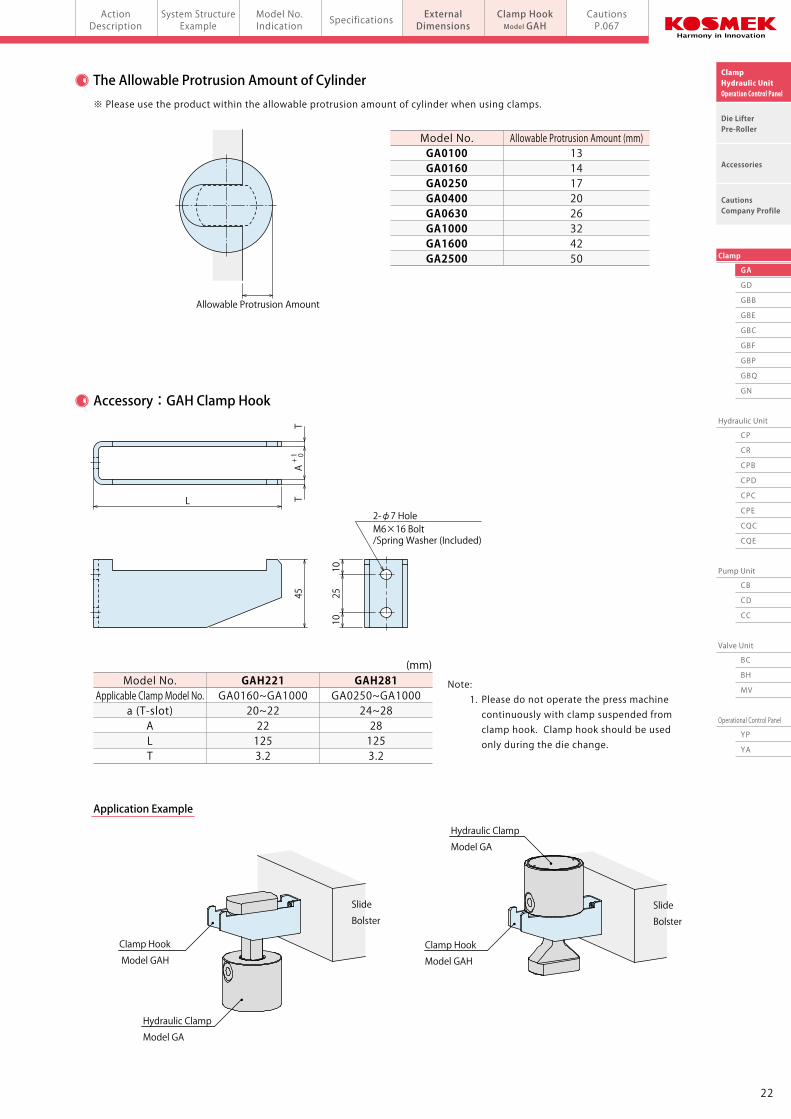
The Allowable Protrusion Amount of Cylinder
Accessory:GAH Clamp Hook
Application Example
※ Please use the product within the allowable protrusion amount of cylinder when using clamps.
Model No. Applicable Clamp Model No. a (T-slot) A L T
GAH221 GA0160~GA1000 20~22 22 125 3.2
GAH281 GA0250~GA1000 24~28 28 125 3.2
Note: 1. Please do not operate the press machine continuously with clamp suspended from clamp hook. Clamp hook should be used only during the die change.
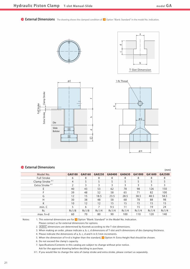
External Dimensions
Extra Stroke
Clamp Stroke
Full Stroke
dh
F
φE
φH
φG
1-Rc Thread
K
CB
A
cd
b
a
T-Slot Dimension
External Dimensions
Model No. Full Stroke Clamp Stroke ※1
Extra Stroke ※1
E F G H K min. C Rc max. h+d
GA0100 6 4 2 40 39 12 30 10 5 Rc1/8 60
GA0160 8 5 3 43 48 15 38 12 6 Rc1/8 70
GA0250 8 5 3 53 52 18.5 48 12 7 Rc1/4 80
GA0400 8 5 3 62 58 23.5 58 15 9.5 Rc1/4 90
GA0630 8 5 3 78 65 28.5 68 15 11 Rc1/4 100
GA1000 8 5 3 98 71 38.5 78 15 15 Rc1/4 110
GA1600 8 5 3 126 82 48.5 88 15 19 Rc1/4 120
GA2500 8 5 3 150 100 58.5 98 15 24 Rc1/4 140
Allowable Protrusion Amount
45
2-φ7 HoleM6×16 Bolt/Spring Washer (Included)
1025
10
AT
TL
+ 1 0
Die
SlideBolster
(mm)
(mm)
Notes: 1. This external dimensions are for Option “Blank: Standard” in the Model No. Indication. Please contact us for external dimensions for options. 2. A B C dimensions are determined by Kosmek according to the T-slot dimenisons. 3. When making an order, please indicate a, b, c, d dimensions of T-slot and h dimensions of die clamping thickness. 4. Please indicate the dimensions of a, b, c, d and h in 0.1mm increments. 5. When the dimension of h+d is higher than the standard, Option H: Extra Height Rod should be chosen. 6. Do not exceed the clamp's capacity. 7. Specifications/Contents in this catalog are subject to change without prior notice. Ask for the approval drawing before deciding to purchase. ※1. If you would like to change the ratio of clamp stroke and extra stroke, please contact us separately.
3
3
The drawing shows the clamped condition of Option “Blank: Standard” in the model No. indication.
Model No. GA0100 GA0160 GA0250 GA0400 GA0630 GA1000 GA1600 GA2500
Allowable Protrusion Amount (mm)1314172026324250
Clamp Hook
Model GAH
Clamp Hook
Model GAH
Hydraulic Clamp
Model GA
Hydraulic Clamp
Model GA
Slide
Bolster
Slide
Bolster
3
2221
GA
GD
GBB
GBE
GBC
GBF
GBP
GBQ
GN
Hydraulic Unit
CP
CR
CPB
CPD
CPC
CPE
CQC
CQE
Pump Unit
CB
CD
CC
Valve Unit
BC
BH
MV
Operational Control Panel
YP
YA
Clamp
ClampHydraulic UnitOperation Control Panel
Die LifterPre-Roller
Accessories
CautionsCompany Profile
ActionDescription
System StructureExample
Model No.Indication Specifications External
DimensionsCautionsP.067
Clamp HookModel GAHmodel GAHydraulic Piston Clamp T-slot Manual-Slide
The Allowable Protrusion Amount of Cylinder
Accessory:GAH Clamp Hook
Application Example
※ Please use the product within the allowable protrusion amount of cylinder when using clamps.
Model No. Applicable Clamp Model No. a (T-slot) A L T
GAH221 GA0160~GA1000 20~22 22 125 3.2
GAH281 GA0250~GA1000 24~28 28 125 3.2
Note: 1. Please do not operate the press machine continuously with clamp suspended from clamp hook. Clamp hook should be used only during the die change.
External Dimensions
Extra Stroke
Clamp Stroke
Full Stroke
dh
F
φE
φH
φG
1-Rc Thread
K
CB
A
cd
b
a
T-Slot Dimension
External Dimensions
Model No. Full Stroke Clamp Stroke ※1
Extra Stroke ※1
E F G H K min. C Rc max. h+d
GA0100 6 4 2 40 39 12 30 10 5 Rc1/8 60
GA0160 8 5 3 43 48 15 38 12 6 Rc1/8 70
GA0250 8 5 3 53 52 18.5 48 12 7 Rc1/4 80
GA0400 8 5 3 62 58 23.5 58 15 9.5 Rc1/4 90
GA0630 8 5 3 78 65 28.5 68 15 11 Rc1/4 100
GA1000 8 5 3 98 71 38.5 78 15 15 Rc1/4 110
GA1600 8 5 3 126 82 48.5 88 15 19 Rc1/4 120
GA2500 8 5 3 150 100 58.5 98 15 24 Rc1/4 140
Allowable Protrusion Amount45
2-φ7 HoleM6×16 Bolt/Spring Washer (Included)
1025
10
AT
TL
+ 1 0
Die
SlideBolster
(mm)
(mm)
Notes: 1. This external dimensions are for Option “Blank: Standard” in the Model No. Indication. Please contact us for external dimensions for options. 2. A B C dimensions are determined by Kosmek according to the T-slot dimenisons. 3. When making an order, please indicate a, b, c, d dimensions of T-slot and h dimensions of die clamping thickness. 4. Please indicate the dimensions of a, b, c, d and h in 0.1mm increments. 5. When the dimension of h+d is higher than the standard, Option H: Extra Height Rod should be chosen. 6. Do not exceed the clamp's capacity. 7. Specifications/Contents in this catalog are subject to change without prior notice. Ask for the approval drawing before deciding to purchase. ※1. If you would like to change the ratio of clamp stroke and extra stroke, please contact us separately.
3
3
The drawing shows the clamped condition of Option “Blank: Standard” in the model No. indication.
Model No. GA0100 GA0160 GA0250 GA0400 GA0630 GA1000 GA1600 GA2500
Allowable Protrusion Amount (mm)1314172026324250
Clamp Hook
Model GAH
Clamp Hook
Model GAH
Hydraulic Clamp
Model GA
Hydraulic Clamp
Model GA
Slide
Bolster
Slide
Bolster
3
2221
GA
GD
GBB
GBE
GBC
GBF
GBP
GBQ
GN
Hydraulic Unit
CP
CR
CPB
CPD
CPC
CPE
CQC
CQE
Pump Unit
CB
CD
CC
Valve Unit
BC
BH
MV
Operational Control Panel
YP
YA
Clamp
ClampHydraulic UnitOperation Control Panel
Die LifterPre-Roller
Accessories
CautionsCompany Profile
CautionsHydraulic Clamp Cautions model GA/GD/GBB/GBE/GBC/GBF/GBP/GBQ/GN
Cautions
● Notes for Design
1)Check Specifications ● Please use each product according to its specifications. ● Operating pressure is 25MPa. Operating pressure of GN clamp:Hydraulic pressure for lock is 25MPa. Pneumatic pressure for release is 0.4~0.5MPa. Do not use clamps with excessive operating pressure. Falling down of the die due to the damage on clamps leads to injury accident. In order to reduce clamping force, use them with lower operating pressure.
2)Check the Die Clamping Thickness ● Please check the die clamping thickness. The die clamping thickness of GN clamp should be h±0.5mm. If using dies other than prescribed, clamps cannot conduct locking action normally and it leads to accident or injury.
3)Clamp surface and T-slot must be parallel to mounting surface of the die. ● If clamp surface is not even or parallel, excessive force is applied to the clamp and it deforms main body and lever of the clamp resulting in accident or injury.
4)Make sure that advance/retraction of the clamp is smoothly conducted.(Model GD / GBE / GBF) ● Please control air cylinder for slide with two-position double solenoid (with detent). ● Supply 0.4MPa or more air pressure to air cylinder. ● Please adjust the moving speed of the clamp with speed controller to be fully stroked within 1 to 2 seconds. ● Do not set the proximity switch to the die surface near the U-cut, since it is used as forward-end detection. ● The clamp sliding surface must be smooth (without any bumps).
5)Make sure that dust, sand, cutting chips or blank pieces do not enter the clamp. ● Clamp does not operate smoothly and may be damaged.
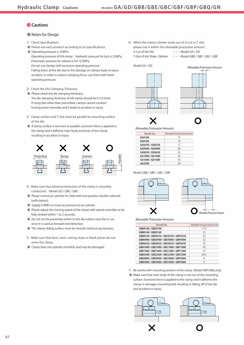
6)When the clamp cylinder sticks out of U-cut or T-slot, please use it within the allowable protrusion amount. U-Cut of the Die ・・・Model GA / GD T-Slot of the Slider / Bolster ・・・Model GBB / GBE / GBC / GBF
Model GA / GD
Model GBB / GBE / GBC / GBF
7)Be careful with mounting position of the clamp. (Model GBP/GBQ only) ● Make sure that main body of the clamp is not out of the mounting surface. Excessive force is applied to the clamp and it deforms the clamp or damages mounting bolt resulting in falling off of the die and accident or injury.
Allowable Protrusion Amount (mm)1314172026324250
Model No. GA0100 GA0160 GA0250 / GD0250 GA0400 / GD0400 GA0630 / GD0630 GA1000 / GD1000 GA1600 / GD1600 GA2500
Allowable Protrusion Amount
Allowable Protrusion Amount
Allowable Protrusion Amount (mm)17.521253239455769.500
Model No. GBB0100 / GBE0100 GBB0160 / GBE0160 GBB0250 / GBE0250 / GBC0250 / GBF0250 GBB0400 / GBE0400 / GBC0400 / GBF0400 GBB0630 / GBE0630 / GBC0630 / GBF0630 GBB1000 / GBE1000 / GBC1000 / GBF1000 GBB1600 / GBE1600 / GBC1600 / GBF1600 GBB2500 / GBE2500 / GBC2500 / GBF2500 GBB4000 / GBE4000 / GBC4000 / GBF4000 GBB5000 / GBE5000 / GBC5000 / GBF5000
Projection Uneven
Parallel
Bump
Allowable Protrusion Amount
Allowable Protrusion Amount
● Installation Notes
1)Check the fluid to use. ● Please use the appropriate fluid by referring to the Hydraulic Fluid List. ● If using hydraulic oil having viscosity higher than viscosity grade ISO-VG-32, action time will be longer. ● If using it at low temperature, action time will be longer because the viscosity of hydraulic oil becomes higher.
2)Procedure before Piping ● The pipeline, piping connector and fixture circuits should be cleaned by thorough flushing. The dust and cutting chips in the circuit may lead to fluid leakage and malfunction. (There is no filter provided with this product for prevention of contaminants in the hydraulic piping or hydraulic system.)
3)Applying Sealing Tape ● Wrap with tape 1 to 2 times following the screwing direction. When piping, be careful that contaminants such as sealing tape do not enter in products. Pieces of the sealing tape can lead to oil leaks and malfunction.
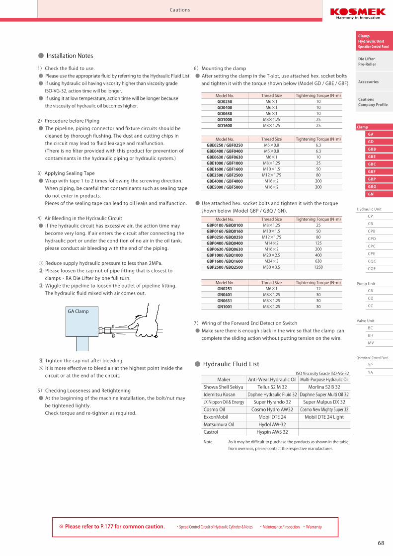
4)Air Bleeding in the Hydraulic Circuit ● If the hydraulic circuit has excessive air, the action time may become very long. If air enters the circuit after connecting the hydraulic port or under the condition of no air in the oil tank, please conduct air bleeding with the end of the piping.
① Reduce supply hydraulic pressure to less than 2MPa. ② Please loosen the cap nut of pipe fitting that is closest to clamps・RA Die Lifter by one full turn. ③ Wiggle the pipeline to loosen the outlet of pipeline fitting. The hydraulic fluid mixed with air comes out.
④ Tighten the cap nut after bleeding. ⑤ It is more effective to bleed air at the highest point inside the circuit or at the end of the circuit.
5)Checking Looseness and Retightening ● At the beginning of the machine installation, the bolt/nut may be tightened lightly. Check torque and re-tighten as required.
6)Mounting the clamp ● After setting the clamp in the T-slot, use attached hex. socket bolts and tighten it with the torque shown below (Model GD / GBE / GBF).
● Use attached hex. socket bolts and tighten it with the torque shown below (Model GBP / GBQ / GN).
7)Wiring of the Forward End Detection Switch ● Make sure there is enough slack in the wire so that the clamp can complete the sliding action without putting tension on the wire.
Tightening Torque (N・m) 10 10 10 25 25
Thread SizeM6×1M6×1M6×1M8×1.25M8×1.25
Model No.GD0250GD0400GD0630GD1000GD1600
Tightening Torque (N・m) 6.3 6.3 10 25 50 80 200 200
Thread SizeM5×0.8M5×0.8M6×1M8×1.25M10×1.5M12×1.75M16×2M16×2
Model No.GBE0250 / GBF0250GBE0400 / GBF0400GBE0630 / GBF0630GBE1000 / GBF1000GBE1600 / GBF1600GBE2500 / GBF2500GBE4000 / GBF4000GBE5000 / GBF5000
Tightening Torque (N・m) 12 30 30 30
Thread SizeM6×1M8×1.25M8×1.25M8×1.25
Model No.GN0251GN0401GN0631GN1001
Tightening Torque (N・m) 25 50 80 125 200 400 630 1250
Thread SizeM8×1.25M10×1.5M12×1.75M14×2M16×2M20×2.5M24×3M30×3.5
Model No.GBP0100 /GBQ0100GBP0160 /GBQ0160GBP0250 /GBQ0250GBP0400 /GBQ0400GBP0630 /GBQ0630GBP1000 /GBQ1000GBP1600 /GBQ1600GBP2500 /GBQ2500
・ Speed Control Circuit of Hydraulic Cylinder & Notes ・ Maintenance / Inspection ・ Warranty※ Please refer to P.177 for common caution.
GA Clamp
● Hydraulic Fluid List
Showa Shell SekiyuIdemitsu KosanJX Nippon Oil & EnergyCosmo OilExxonMobilMatsumura OilCastrol
Maker Anti-Wear Hydraulic OilTellus S2 M 32
Daphne Hydraulic Fluid 32Super Hyrando 32Cosmo Hydro AW32Mobil DTE 24Hydol AW-32Hyspin AWS 32
Multi-Purpose Hydraulic OilMorlina S2 B 32
Daphne Super Multi Oil 32Super Mulpus DX 32Cosmo New Mighty Super 32Mobil DTE 24 Light
Note As it may be difficult to purchase the products as shown in the table from overseas, please contact the respective manufacturer.
ISO Viscosity Grade ISO-VG-32
6867
GA
GD
GBB
GBE
GBC
GBF
GBP
GBQ
GN
Hydraulic Unit
CP
CR
CPB
CPD
CPC
CPE
CQC
CQE
Pump Unit
CB
CD
CC
Valve Unit
BC
BH
MV
Operational Control Panel
YP
YA
Clamp
ClampHydraulic UnitOperation Control Panel
Die LifterPre-Roller
Accessories
CautionsCompany Profile
CautionsHydraulic Clamp Cautions model GA/GD/GBB/GBE/GBC/GBF/GBP/GBQ/GN
Cautions
● Notes for Design
1)Check Specifications ● Please use each product according to its specifications. ● Operating pressure is 25MPa. Operating pressure of GN clamp:Hydraulic pressure for lock is 25MPa. Pneumatic pressure for release is 0.4~0.5MPa. Do not use clamps with excessive operating pressure. Falling down of the die due to the damage on clamps leads to injury accident. In order to reduce clamping force, use them with lower operating pressure.
2)Check the Die Clamping Thickness ● Please check the die clamping thickness. The die clamping thickness of GN clamp should be h±0.5mm. If using dies other than prescribed, clamps cannot conduct locking action normally and it leads to accident or injury.
3)Clamp surface and T-slot must be parallel to mounting surface of the die. ● If clamp surface is not even or parallel, excessive force is applied to the clamp and it deforms main body and lever of the clamp resulting in accident or injury.
4)Make sure that advance/retraction of the clamp is smoothly conducted.(Model GD / GBE / GBF) ● Please control air cylinder for slide with two-position double solenoid (with detent). ● Supply 0.4MPa or more air pressure to air cylinder. ● Please adjust the moving speed of the clamp with speed controller to be fully stroked within 1 to 2 seconds. ● Do not set the proximity switch to the die surface near the U-cut, since it is used as forward-end detection. ● The clamp sliding surface must be smooth (without any bumps).
5)Make sure that dust, sand, cutting chips or blank pieces do not enter the clamp. ● Clamp does not operate smoothly and may be damaged.
6)When the clamp cylinder sticks out of U-cut or T-slot, please use it within the allowable protrusion amount. U-Cut of the Die ・・・Model GA / GD T-Slot of the Slider / Bolster ・・・Model GBB / GBE / GBC / GBF
Model GA / GD
Model GBB / GBE / GBC / GBF
7)Be careful with mounting position of the clamp. (Model GBP/GBQ only) ● Make sure that main body of the clamp is not out of the mounting surface. Excessive force is applied to the clamp and it deforms the clamp or damages mounting bolt resulting in falling off of the die and accident or injury.
Allowable Protrusion Amount (mm)1314172026324250
Model No. GA0100 GA0160 GA0250 / GD0250 GA0400 / GD0400 GA0630 / GD0630 GA1000 / GD1000 GA1600 / GD1600 GA2500
Allowable Protrusion Amount
Allowable Protrusion Amount
Allowable Protrusion Amount (mm)17.521253239455769.500
Model No. GBB0100 / GBE0100 GBB0160 / GBE0160 GBB0250 / GBE0250 / GBC0250 / GBF0250 GBB0400 / GBE0400 / GBC0400 / GBF0400 GBB0630 / GBE0630 / GBC0630 / GBF0630 GBB1000 / GBE1000 / GBC1000 / GBF1000 GBB1600 / GBE1600 / GBC1600 / GBF1600 GBB2500 / GBE2500 / GBC2500 / GBF2500 GBB4000 / GBE4000 / GBC4000 / GBF4000 GBB5000 / GBE5000 / GBC5000 / GBF5000
Projection Uneven
Parallel
Bump
Allowable Protrusion Amount
Allowable Protrusion Amount
● Installation Notes
1)Check the fluid to use. ● Please use the appropriate fluid by referring to the Hydraulic Fluid List. ● If using hydraulic oil having viscosity higher than viscosity grade ISO-VG-32, action time will be longer. ● If using it at low temperature, action time will be longer because the viscosity of hydraulic oil becomes higher.
2)Procedure before Piping ● The pipeline, piping connector and fixture circuits should be cleaned by thorough flushing. The dust and cutting chips in the circuit may lead to fluid leakage and malfunction. (There is no filter provided with this product for prevention of contaminants in the hydraulic piping or hydraulic system.)
3)Applying Sealing Tape ● Wrap with tape 1 to 2 times following the screwing direction. When piping, be careful that contaminants such as sealing tape do not enter in products. Pieces of the sealing tape can lead to oil leaks and malfunction.
4)Air Bleeding in the Hydraulic Circuit ● If the hydraulic circuit has excessive air, the action time may become very long. If air enters the circuit after connecting the hydraulic port or under the condition of no air in the oil tank, please conduct air bleeding with the end of the piping.
① Reduce supply hydraulic pressure to less than 2MPa. ② Please loosen the cap nut of pipe fitting that is closest to clamps・RA Die Lifter by one full turn. ③ Wiggle the pipeline to loosen the outlet of pipeline fitting. The hydraulic fluid mixed with air comes out.
④ Tighten the cap nut after bleeding. ⑤ It is more effective to bleed air at the highest point inside the circuit or at the end of the circuit.
5)Checking Looseness and Retightening ● At the beginning of the machine installation, the bolt/nut may be tightened lightly. Check torque and re-tighten as required.
6)Mounting the clamp ● After setting the clamp in the T-slot, use attached hex. socket bolts and tighten it with the torque shown below (Model GD / GBE / GBF).
● Use attached hex. socket bolts and tighten it with the torque shown below (Model GBP / GBQ / GN).
7)Wiring of the Forward End Detection Switch ● Make sure there is enough slack in the wire so that the clamp can complete the sliding action without putting tension on the wire.
Tightening Torque (N・m) 10 10 10 25 25
Thread SizeM6×1M6×1M6×1M8×1.25M8×1.25
Model No.GD0250GD0400GD0630GD1000GD1600
Tightening Torque (N・m) 6.3 6.3 10 25 50 80 200 200
Thread SizeM5×0.8M5×0.8M6×1M8×1.25M10×1.5M12×1.75M16×2M16×2
Model No.GBE0250 / GBF0250GBE0400 / GBF0400GBE0630 / GBF0630GBE1000 / GBF1000GBE1600 / GBF1600GBE2500 / GBF2500GBE4000 / GBF4000GBE5000 / GBF5000
Tightening Torque (N・m) 12 30 30 30
Thread SizeM6×1M8×1.25M8×1.25M8×1.25
Model No.GN0251GN0401GN0631GN1001
Tightening Torque (N・m) 25 50 80 125 200 400 630 1250
Thread SizeM8×1.25M10×1.5M12×1.75M14×2M16×2M20×2.5M24×3M30×3.5
Model No.GBP0100 /GBQ0100GBP0160 /GBQ0160GBP0250 /GBQ0250GBP0400 /GBQ0400GBP0630 /GBQ0630GBP1000 /GBQ1000GBP1600 /GBQ1600GBP2500 /GBQ2500
・ Speed Control Circuit of Hydraulic Cylinder & Notes ・ Maintenance / Inspection ・ Warranty※ Please refer to P.177 for common caution.
GA Clamp
● Hydraulic Fluid List
Showa Shell SekiyuIdemitsu KosanJX Nippon Oil & EnergyCosmo OilExxonMobilMatsumura OilCastrol
Maker Anti-Wear Hydraulic OilTellus S2 M 32
Daphne Hydraulic Fluid 32Super Hyrando 32Cosmo Hydro AW32Mobil DTE 24Hydol AW-32Hyspin AWS 32
Multi-Purpose Hydraulic OilMorlina S2 B 32
Daphne Super Multi Oil 32Super Mulpus DX 32Cosmo New Mighty Super 32Mobil DTE 24 Light
Note As it may be difficult to purchase the products as shown in the table from overseas, please contact the respective manufacturer.
ISO Viscosity Grade ISO-VG-32
6867
GA
GD
GBB
GBE
GBC
GBF
GBP
GBQ
GN
Hydraulic Unit
CP
CR
CPB
CPD
CPC
CPE
CQC
CQE
Pump Unit
CB
CD
CC
Valve Unit
BC
BH
MV
Operational Control Panel
YP
YA
Clamp
ClampHydraulic UnitOperation Control Panel
Die LifterPre-Roller
Accessories
CautionsCompany Profile
CautionsHydraulic Clamp Cautions model GA/GD/GBB/GBE/GBC/GBF/GBP/GBQ/GN
Cautions
● Notes on Handling
1)Shutting down of the machine should be done without load applied to the clamp. ● This can result in the dropping of a die. ● When using it with a press machine, make sure to stop the slide at bottom dead point.
2)It should be handled by qualified personnel. ● The hydraulic machine and air compressor should be handled and maintained by qualified personnel.
3)Do not handle or remove the machine unless the safety protocols are ensured.
① The machine and equipment can only be inspected or prepared when it is confirmed that the preventive devices are in place.
② Before the machine is removed, make sure that the above-mentioned safety measures are in place. Shut off the air of hydraulic source and make sure no pressure exists in the hydraulic circuit.
③ After stopping the machine, do not remove until the temperature cools down.
④ Make sure there is no abnormality in the bolts and respective parts before restarting the machine or equipment.
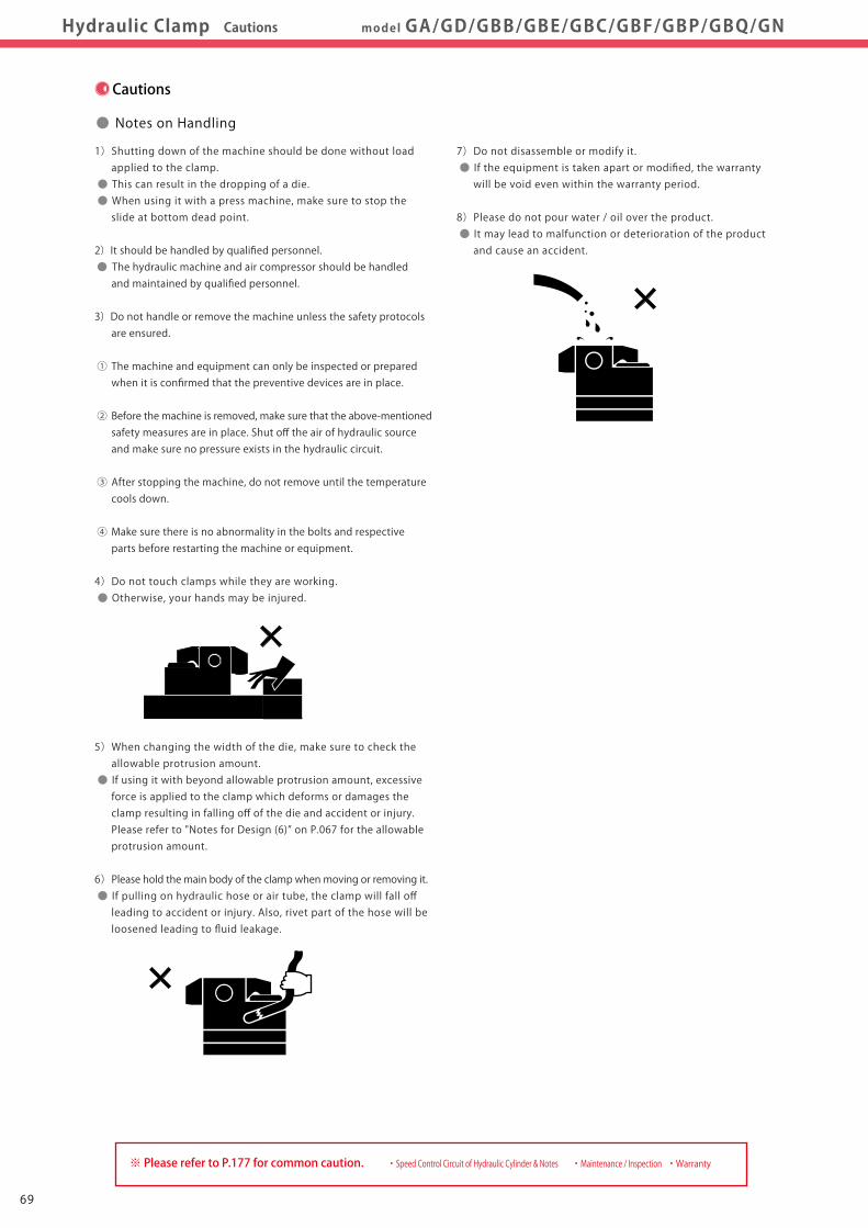
4)Do not touch clamps while they are working. ● Otherwise, your hands may be injured.
5)When changing the width of the die, make sure to check the allowable protrusion amount. ● If using it with beyond allowable protrusion amount, excessive force is applied to the clamp which deforms or damages the clamp resulting in falling off of the die and accident or injury. Please refer to "Notes for Design (6)” on P.067 for the allowable protrusion amount.
6)Please hold the main body of the clamp when moving or removing it. ● If pulling on hydraulic hose or air tube, the clamp will fall off leading to accident or injury. Also, rivet part of the hose will be loosened leading to fluid leakage.
7)Do not disassemble or modify it. ● If the equipment is taken apart or modified, the warranty will be void even within the warranty period.
8)Please do not pour water / oil over the product. ● It may lead to malfunction or deterioration of the product and cause an accident.
・ Speed Control Circuit of Hydraulic Cylinder & Notes ・ Maintenance / Inspection ・ Warranty※ Please refer to P.177 for common caution.
7069
GA
GD
GBB
GBE
GBC
GBF
GBP
GBQ
GN
Hydraulic Unit
CP
CR
CPB
CPD
CPC
CPE
CQC
CQE
Pump Unit
CB
CD
CC
Valve Unit
BC
BH
MV
Operational Control Panel
YP
YA
Clamp
ClampHydraulic UnitOperation Control Panel
Die LifterPre-Roller
Accessories
CautionsCompany Profile
CautionsHydraulic Clamp Cautions model GA/GD/GBB/GBE/GBC/GBF/GBP/GBQ/GN
Cautions
● Notes on Handling
1)Shutting down of the machine should be done without load applied to the clamp. ● This can result in the dropping of a die. ● When using it with a press machine, make sure to stop the slide at bottom dead point.
2)It should be handled by qualified personnel. ● The hydraulic machine and air compressor should be handled and maintained by qualified personnel.
3)Do not handle or remove the machine unless the safety protocols are ensured.
① The machine and equipment can only be inspected or prepared when it is confirmed that the preventive devices are in place.
② Before the machine is removed, make sure that the above-mentioned safety measures are in place. Shut off the air of hydraulic source and make sure no pressure exists in the hydraulic circuit.
③ After stopping the machine, do not remove until the temperature cools down.
④ Make sure there is no abnormality in the bolts and respective parts before restarting the machine or equipment.
4)Do not touch clamps while they are working. ● Otherwise, your hands may be injured.
5)When changing the width of the die, make sure to check the allowable protrusion amount. ● If using it with beyond allowable protrusion amount, excessive force is applied to the clamp which deforms or damages the clamp resulting in falling off of the die and accident or injury. Please refer to "Notes for Design (6)” on P.067 for the allowable protrusion amount.
6)Please hold the main body of the clamp when moving or removing it. ● If pulling on hydraulic hose or air tube, the clamp will fall off leading to accident or injury. Also, rivet part of the hose will be loosened leading to fluid leakage.
7)Do not disassemble or modify it. ● If the equipment is taken apart or modified, the warranty will be void even within the warranty period.
8)Please do not pour water / oil over the product. ● It may lead to malfunction or deterioration of the product and cause an accident.
・ Speed Control Circuit of Hydraulic Cylinder & Notes ・ Maintenance / Inspection ・ Warranty※ Please refer to P.177 for common caution.
7069
Notes on Hydraulic CylinderSpeed Control Unit
Cautions
Hydraulic Fluid List
Notes on Handling
Maintenance / Inspection
Warranty
Company Profile
Company Profile
Our Products
History
Sales Office
ClampHydraulic UnitOperation Control Panel
Die LifterPre-Roller
Accessories
CautionsCompany Profile
CautionsInstallation Notes
(For Hydraulic Series) Hydraulic Fluid ListInstallation Notes(For Hydraulic Series) Maintenance / Inspection WarrantyNotes on HandlingHydraulic Fluid List Notes on Hydraulic Cylinder
Speed Control Unit
Installation Notes(For Hydraulic Series)
Cautions
● Installation Notes (Cautions for Hydraulic Series)
1)Check the fluid to use
● Please use the appropriate fluid by referring to the Hydraulic Fluid List.
● If hydraulic oil with viscosity grade higher than ISO-VG-32 is used, action time would be longer. ● If using it at low temperature, action time will be longer because the viscosity of hydraulic oil becomes higher.
2)Procedure before Piping
● The pipeline, piping connector and fixture circuits should be
cleaned by thorough flushing.
● The dust and cutting chips in the circuit may lead to fluid
leakage and malfunction.
● Our products except some valves are not equipped with
protective function to prevent dust and cutting chips going
into the hydraulic system and pipeline.
3)Applying Sealing Tape
● Wrap with tape 1 to 2 times following the screwing direction.
● Pieces of the sealing tape can lead to air leaks and malfunction.
● In order to prevent a foreign substance from going into
the product during piping, it should be carefully cleaned.
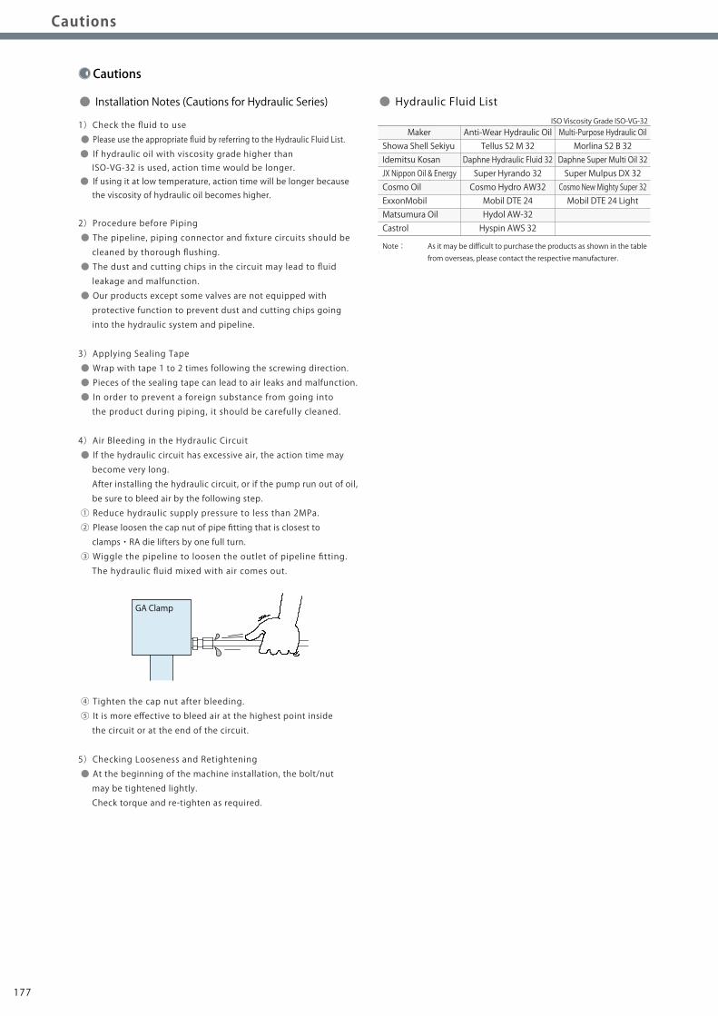
4)Air Bleeding in the Hydraulic Circuit
● If the hydraulic circuit has excessive air, the action time may
become very long.
After installing the hydraulic circuit, or if the pump run out of oil,
be sure to bleed air by the following step.
① Reduce hydraulic supply pressure to less than 2MPa.
② Please loosen the cap nut of pipe fitting that is closest to
clamps・RA die lifters by one full turn.
③ Wiggle the pipeline to loosen the outlet of pipeline fitting.
The hydraulic fluid mixed with air comes out.
④ Tighten the cap nut after bleeding.
⑤ It is more effective to bleed air at the highest point inside
the circuit or at the end of the circuit.
5)Checking Looseness and Retightening
● At the beginning of the machine installation, the bolt/nut
may be tightened lightly.
Check torque and re-tighten as required.
Showa Shell SekiyuIdemitsu KosanJX Nippon Oil & EnergyCosmo OilExxonMobilMatsumura OilCastrol
Maker Anti-Wear Hydraulic OilTellus S2 M 32
Daphne Hydraulic Fluid 32Super Hyrando 32Cosmo Hydro AW32Mobil DTE 24Hydol AW-32Hyspin AWS 32
Multi-Purpose Hydraulic OilMorlina S2 B 32
Daphne Super Multi Oil 32Super Mulpus DX 32Cosmo New Mighty Super 32Mobil DTE 24 Light
Note: As it may be difficult to purchase the products as shown in the table from overseas, please contact the respective manufacturer.
● Hydraulic Fluid ListISO Viscosity Grade ISO-VG-32
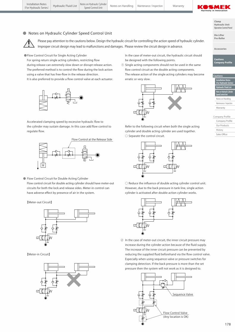
● Flow Control Circuit for Single Acting Cylinder
For spring return single acting cylinders, restricting flow
during release can extremely slow down or disrupt release action.
The preferred method is to control the flow during the lock action
using a valve that has free-flow in the release direction.
It is also preferred to provide a flow control valve at each actuator.
Accelerated clamping speed by excessive hydraulic flow to
the cylinder may sustain damage. In this case add flow control to
regulate flow.
● Flow Control Circuit for Double Acting Cylinder
Flow control circuit for double acting cylinder should have meter-out
circuits for both the lock and release sides. Meter-in control can
have adverse effect by presence of air in the system.
【Meter-out Circuit】
【Meter-in Circuit】
In the case of meter-out circuit, the hydraulic circuit should
be designed with the following points.
① Single acting components should not be used in the same
flow control circuit as the double acting components.
The release action of the single acting cylinders may become
erratic or very slow.
Refer to the following circuit when both the single acting
cylinder and double acting cylinder are used together.
○ Separate the control circuit.
○ Reduce the influence of double acting cylinder control unit.
However, due to the back pressure in tank line, single action
cylinder is activated after double action cylinder works.
② In the case of meter-out circuit, the inner circuit pressure may
increase during the cylinder action because of the fluid supply.
The increase of the inner circuit pressure can be prevented by
reducing the supplied fluid beforehand via the flow control valve.
Especially when using sequence valve or pressure switches for
clamping detection. If the back pressure is more than the set
pressure then the system will not work as it is designed to.
Flow Control at the Release Side
W
Flow Control Valve(Any location is OK)
Sequence Valve
● Notes on Hydraulic Cylinder Speed Control Unit
Please pay attention to the cautions below. Design the hydraulic circuit for controlling the action speed of hydraulic cylinder.
Improper circuit design may lead to malfunctions and damages. Please review the circuit design in advance.!
GA Clamp
178177
Notes on Hydraulic CylinderSpeed Control Unit
Cautions
Hydraulic Fluid List
Notes on Handling
Maintenance / Inspection
Warranty
Company Profile
Company Profile
Our Products
History
Sales Office
ClampHydraulic UnitOperation Control Panel
Die LifterPre-Roller
Accessories
CautionsCompany Profile
CautionsInstallation Notes
(For Hydraulic Series) Hydraulic Fluid ListInstallation Notes(For Hydraulic Series) Maintenance / Inspection WarrantyNotes on HandlingHydraulic Fluid List Notes on Hydraulic Cylinder
Speed Control Unit
Installation Notes(For Hydraulic Series)
Cautions
● Installation Notes (Cautions for Hydraulic Series)
1)Check the fluid to use
● Please use the appropriate fluid by referring to the Hydraulic Fluid List.
● If hydraulic oil with viscosity grade higher than ISO-VG-32 is used, action time would be longer. ● If using it at low temperature, action time will be longer because the viscosity of hydraulic oil becomes higher.
2)Procedure before Piping
● The pipeline, piping connector and fixture circuits should be
cleaned by thorough flushing.
● The dust and cutting chips in the circuit may lead to fluid
leakage and malfunction.
● Our products except some valves are not equipped with
protective function to prevent dust and cutting chips going
into the hydraulic system and pipeline.
3)Applying Sealing Tape
● Wrap with tape 1 to 2 times following the screwing direction.
● Pieces of the sealing tape can lead to air leaks and malfunction.
● In order to prevent a foreign substance from going into
the product during piping, it should be carefully cleaned.
4)Air Bleeding in the Hydraulic Circuit
● If the hydraulic circuit has excessive air, the action time may
become very long.
After installing the hydraulic circuit, or if the pump run out of oil,
be sure to bleed air by the following step.
① Reduce hydraulic supply pressure to less than 2MPa.
② Please loosen the cap nut of pipe fitting that is closest to
clamps・RA die lifters by one full turn.
③ Wiggle the pipeline to loosen the outlet of pipeline fitting.
The hydraulic fluid mixed with air comes out.
④ Tighten the cap nut after bleeding.
⑤ It is more effective to bleed air at the highest point inside
the circuit or at the end of the circuit.
5)Checking Looseness and Retightening
● At the beginning of the machine installation, the bolt/nut
may be tightened lightly.
Check torque and re-tighten as required.
Showa Shell SekiyuIdemitsu KosanJX Nippon Oil & EnergyCosmo OilExxonMobilMatsumura OilCastrol
Maker Anti-Wear Hydraulic OilTellus S2 M 32
Daphne Hydraulic Fluid 32Super Hyrando 32Cosmo Hydro AW32Mobil DTE 24Hydol AW-32Hyspin AWS 32
Multi-Purpose Hydraulic OilMorlina S2 B 32
Daphne Super Multi Oil 32Super Mulpus DX 32Cosmo New Mighty Super 32Mobil DTE 24 Light
Note: As it may be difficult to purchase the products as shown in the table from overseas, please contact the respective manufacturer.
● Hydraulic Fluid ListISO Viscosity Grade ISO-VG-32
● Flow Control Circuit for Single Acting Cylinder
For spring return single acting cylinders, restricting flow
during release can extremely slow down or disrupt release action.
The preferred method is to control the flow during the lock action
using a valve that has free-flow in the release direction.
It is also preferred to provide a flow control valve at each actuator.
Accelerated clamping speed by excessive hydraulic flow to
the cylinder may sustain damage. In this case add flow control to
regulate flow.
● Flow Control Circuit for Double Acting Cylinder
Flow control circuit for double acting cylinder should have meter-out
circuits for both the lock and release sides. Meter-in control can
have adverse effect by presence of air in the system.
【Meter-out Circuit】
【Meter-in Circuit】
In the case of meter-out circuit, the hydraulic circuit should
be designed with the following points.
① Single acting components should not be used in the same
flow control circuit as the double acting components.
The release action of the single acting cylinders may become
erratic or very slow.
Refer to the following circuit when both the single acting
cylinder and double acting cylinder are used together.
○ Separate the control circuit.
○ Reduce the influence of double acting cylinder control unit.
However, due to the back pressure in tank line, single action
cylinder is activated after double action cylinder works.
② In the case of meter-out circuit, the inner circuit pressure may
increase during the cylinder action because of the fluid supply.
The increase of the inner circuit pressure can be prevented by
reducing the supplied fluid beforehand via the flow control valve.
Especially when using sequence valve or pressure switches for
clamping detection. If the back pressure is more than the set
pressure then the system will not work as it is designed to.
Flow Control at the Release Side
W
Flow Control Valve(Any location is OK)
Sequence Valve
● Notes on Hydraulic Cylinder Speed Control Unit
Please pay attention to the cautions below. Design the hydraulic circuit for controlling the action speed of hydraulic cylinder.
Improper circuit design may lead to malfunctions and damages. Please review the circuit design in advance.!
GA Clamp
178177
Notes on Hydraulic CylinderSpeed Control Unit
Installation Notes(For Hydraulic Series)
Hydraulic Fluid List
Notes on Handling
Maintenance / Inspection
Warranty
Cautions
Company Profile
ClampHydraulic UnitOperation Control Panel
Die LifterPre-Roller
Accessories
CautionsCompany Profile
Company Profile
Our Products
History
Sales Office
CautionsInstallation Notes
(For Hydraulic Series) Hydraulic Fluid List Notes on Hydraulic CylinderSpeed Control Unit Maintenance / Inspection WarrantyNotes on Handling
1)Warranty Period
● The product warranty period is 18 months from shipment from
our factory or 12 months from initial use, whichever is earlier.
2)Warranty Scope
● If the product is damaged or malfunctions during the warranty
period due to faulty design, materials or workmanship, we will
replace or repair the defective part at our expense.
Defects or failures caused by the following are not covered.
① If the stipulated maintenance and inspection are not carried out.
② If the product is used while it is not suitable for use based on
the operator’ s judgment, resulting in defect.
③ If it is used or handled in inappropriate way by the operator.
(Including damage caused by the misconduct of the third party.)
④ If the defect is caused by reasons other than our responsibility.
⑤ If repair or modifications are carried out by anyone other than Kosmek,
or without our approval and confirmation, it will void warranty.
⑥ Other caused by natural disasters or calamities not attributable to
our company.
⑦ Parts or replacement expenses due to parts consumption and
deterioration.
(Such as rubber, plastic, seal material and some electric components.)
Damages excluding from direct result of a product defect shall be
excluded from the warranty.
● Warranty
Cautions
1)It should be handled by qualified personnel.
● The hydraulic machine / air compressor should be handled
and maintained by qualified personnel.
2)Do not handle or remove the machine unless
the safety protocols are ensured.
① The machine and equipment can only be inspected or prepared
when it is confirmed that the preventive devices are in place.
② Before the machine is removed, make sure that the above-mentioned
safety measures are in place. Shut off the air of hydraulic source
and make sure no pressure exists in the hydraulic and air circuit.
③ After stopping the machine, do not remove until the temperature
cools down.
④ Make sure there is no abnormality in the bolts and respective parts
before restarting the machine or equipment.
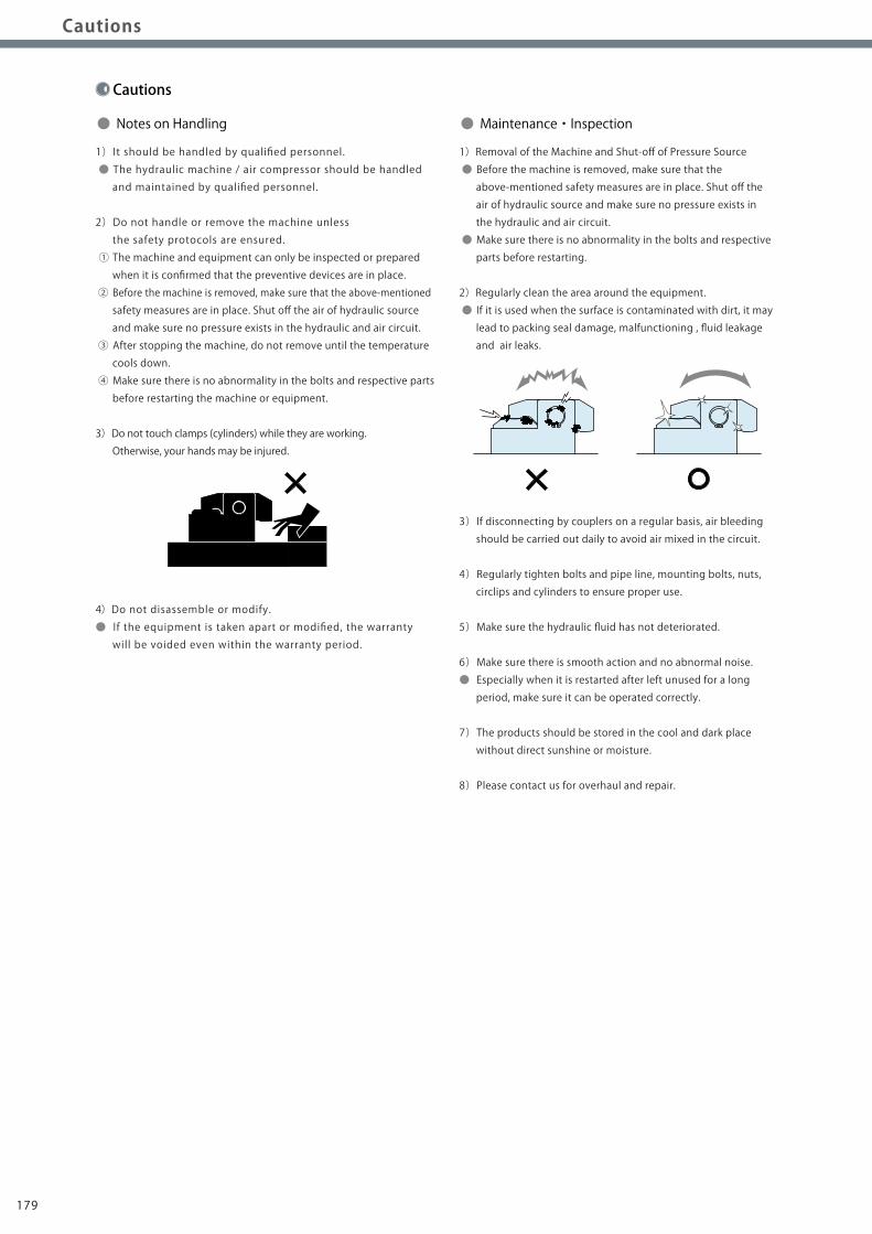
3)Do not touch clamps (cylinders) while they are working.
Otherwise, your hands may be injured.
4)Do not disassemble or modify.
● If the equipment is taken apart or modified, the warranty
will be voided even within the warranty period.
1)Removal of the Machine and Shut-off of Pressure Source
● Before the machine is removed, make sure that the
above-mentioned safety measures are in place. Shut off the
air of hydraulic source and make sure no pressure exists in
the hydraulic and air circuit.
● Make sure there is no abnormality in the bolts and respective
parts before restarting.
2)Regularly clean the area around the equipment.
● If it is used when the surface is contaminated with dirt, it may
lead to packing seal damage, malfunctioning , fluid leakage
and air leaks.
3)If disconnecting by couplers on a regular basis, air bleeding
should be carried out daily to avoid air mixed in the circuit.
4)Regularly tighten bolts and pipe line, mounting bolts, nuts,
circlips and cylinders to ensure proper use.
5)Make sure the hydraulic fluid has not deteriorated.
6)Make sure there is smooth action and no abnormal noise.
● Especially when it is restarted after left unused for a long
period, make sure it can be operated correctly.
7)The products should be stored in the cool and dark place
without direct sunshine or moisture.
8)Please contact us for overhaul and repair.
● Notes on Handling ● Maintenance・Inspection
180179
Notes on Hydraulic CylinderSpeed Control Unit
Installation Notes(For Hydraulic Series)
Hydraulic Fluid List
Notes on Handling
Maintenance / Inspection
Warranty
Cautions
Company Profile
ClampHydraulic UnitOperation Control Panel
Die LifterPre-Roller
Accessories
CautionsCompany Profile
Company Profile
Our Products
History
Sales Office
CautionsInstallation Notes
(For Hydraulic Series) Hydraulic Fluid List Notes on Hydraulic CylinderSpeed Control Unit Maintenance / Inspection WarrantyNotes on Handling
1)Warranty Period
● The product warranty period is 18 months from shipment from
our factory or 12 months from initial use, whichever is earlier.
2)Warranty Scope
● If the product is damaged or malfunctions during the warranty
period due to faulty design, materials or workmanship, we will
replace or repair the defective part at our expense.
Defects or failures caused by the following are not covered.
① If the stipulated maintenance and inspection are not carried out.
② If the product is used while it is not suitable for use based on
the operator’ s judgment, resulting in defect.
③ If it is used or handled in inappropriate way by the operator.
(Including damage caused by the misconduct of the third party.)
④ If the defect is caused by reasons other than our responsibility.
⑤ If repair or modifications are carried out by anyone other than Kosmek,
or without our approval and confirmation, it will void warranty.
⑥ Other caused by natural disasters or calamities not attributable to
our company.
⑦ Parts or replacement expenses due to parts consumption and
deterioration.
(Such as rubber, plastic, seal material and some electric components.)
Damages excluding from direct result of a product defect shall be
excluded from the warranty.
● Warranty
Cautions
1)It should be handled by qualified personnel.
● The hydraulic machine / air compressor should be handled
and maintained by qualified personnel.
2)Do not handle or remove the machine unless
the safety protocols are ensured.
① The machine and equipment can only be inspected or prepared
when it is confirmed that the preventive devices are in place.
② Before the machine is removed, make sure that the above-mentioned
safety measures are in place. Shut off the air of hydraulic source
and make sure no pressure exists in the hydraulic and air circuit.
③ After stopping the machine, do not remove until the temperature
cools down.
④ Make sure there is no abnormality in the bolts and respective parts
before restarting the machine or equipment.
3)Do not touch clamps (cylinders) while they are working.
Otherwise, your hands may be injured.
4)Do not disassemble or modify.
● If the equipment is taken apart or modified, the warranty
will be voided even within the warranty period.
1)Removal of the Machine and Shut-off of Pressure Source
● Before the machine is removed, make sure that the
above-mentioned safety measures are in place. Shut off the
air of hydraulic source and make sure no pressure exists in
the hydraulic and air circuit.
● Make sure there is no abnormality in the bolts and respective
parts before restarting.
2)Regularly clean the area around the equipment.
● If it is used when the surface is contaminated with dirt, it may
lead to packing seal damage, malfunctioning , fluid leakage
and air leaks.
3)If disconnecting by couplers on a regular basis, air bleeding
should be carried out daily to avoid air mixed in the circuit.
4)Regularly tighten bolts and pipe line, mounting bolts, nuts,
circlips and cylinders to ensure proper use.
5)Make sure the hydraulic fluid has not deteriorated.
6)Make sure there is smooth action and no abnormal noise.
● Especially when it is restarted after left unused for a long
period, make sure it can be operated correctly.
7)The products should be stored in the cool and dark place
without direct sunshine or moisture.
8)Please contact us for overhaul and repair.
● Notes on Handling ● Maintenance・Inspection
180179


![corporate.haynes.co.uk · condensator gewoon lampje autoradio ... circuit breaker circuitdiagram clamp clamp bolt] ... compression tester computer condenser (capacitor)](https://img.pdfslide.us/doc/110x75/5af936c47f8b9ad2208d917f/gewoon-lampje-autoradio-circuit-breaker-circuitdiagram-clamp-clamp-bolt-.jpg)