Embed Size (px)
Citation preview
Hydraulic Control Valves M3, M1 & MV Series
ContentsCompany profile .........................................................
Our advantages ..........................................................
Principle of operation ......................................................
Operational features ...........................................................
Multi-Valve ...........................................................................
Pressure reducing valves ....................................................
Pressure & flow regulation valves .......................................
Pressure sustaining valves .................................................
Surge anticipating valves ...................................................
Flow control valves .............................................................
Booster pump control valves ...............................................
Reservoir level control valves .............................................
Three-way hydraulic pool valves .........................................
Security valves ....................................................................
Burst control valves .............................................................
Technical data .....................................................................
Dimensions & weights .........................................................
Pilots table ..........................................................................
M1 exploded view ...............................................................
M3 exploded view ...............................................................
4
5
6-7
8
9
10
11
12
13
14
15
16
17
18-19
20
21-24
25-26
27
28-29
30
3
•
•••••
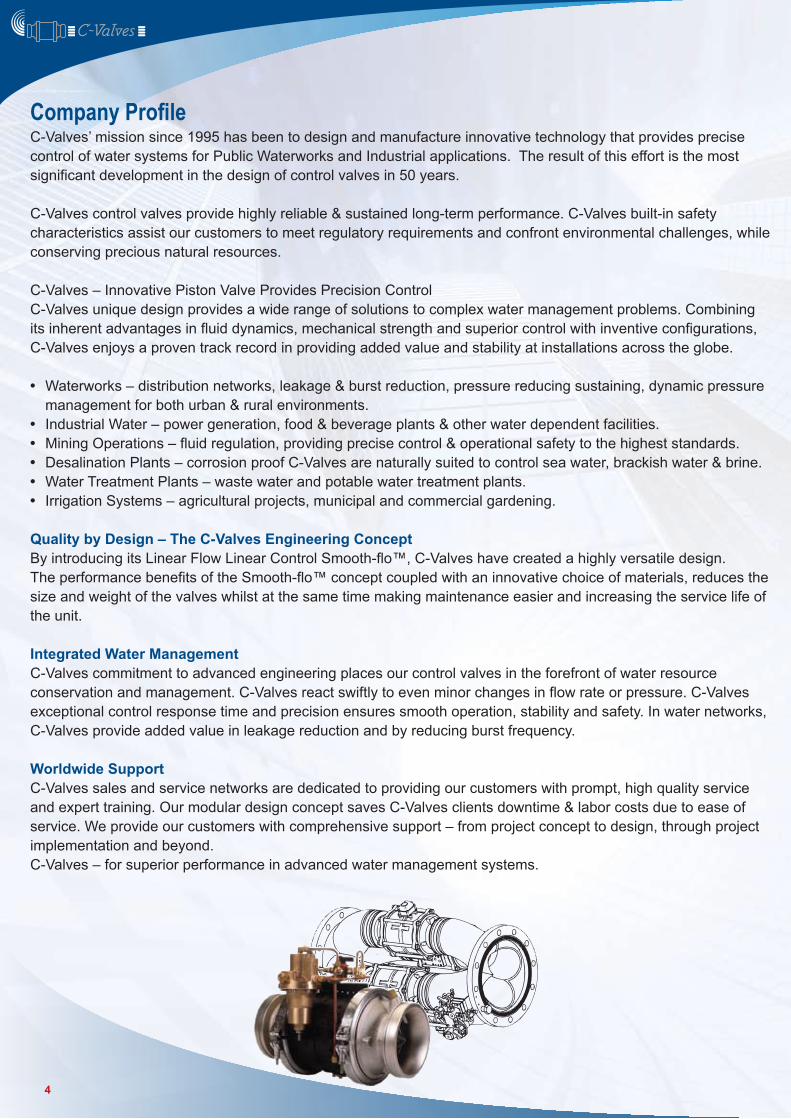
C-Valves’ mission since 1995 has been to design and manufacture innovative technology that provides precise control of water systems for Public Waterworks and Industrial applications. The result of this effort is the most significant development in the design of control valves in 50 years.
C-Valves control valves provide highly reliable & sustained long-term performance. C-Valves built-in safety characteristics assist our customers to meet regulatory requirements and confront environmental challenges, while conserving precious natural resources.
C-Valves – Innovative Piston Valve Provides Precision ControlC-Valves unique design provides a wide range of solutions to complex water management problems. Combining its inherent advantages in fluid dynamics, mechanical strength and superior control with inventive configurations, C-Valves enjoys a proven track record in providing added value and stability at installations across the globe.
Waterworks – distribution networks, leakage & burst reduction, pressure reducing sustaining, dynamic pressure management for both urban & rural environments. Industrial Water – power generation, food & beverage plants & other water dependent facilities.Mining Operations – fluid regulation, providing precise control & operational safety to the highest standards. Desalination Plants – corrosion proof C-Valves are naturally suited to control sea water, brackish water & brine. Water Treatment Plants – waste water and potable water treatment plants. Irrigation Systems – agricultural projects, municipal and commercial gardening.
Quality by Design – The C-Valves Engineering Concept By introducing its Linear Flow Linear Control Smooth-flo™, C-Valves have created a highly versatile design.The performance benefits of the Smooth-flo™ concept coupled with an innovative choice of materials, reduces the size and weight of the valves whilst at the same time making maintenance easier and increasing the service life of the unit.
Integrated Water ManagementC-Valves commitment to advanced engineering places our control valves in the forefront of water resource conservation and management. C-Valves react swiftly to even minor changes in flow rate or pressure. C-Valves exceptional control response time and precision ensures smooth operation, stability and safety. In water networks, C-Valves provide added value in leakage reduction and by reducing burst frequency.
Worldwide SupportC-Valves sales and service networks are dedicated to providing our customers with prompt, high quality service and expert training. Our modular design concept saves C-Valves clients downtime & labor costs due to ease of service. We provide our customers with comprehensive support – from project concept to design, through project implementation and beyond.C-Valves – for superior performance in advanced water management systems.
Company Profile
4
Accurate and Stable Pressure RegulationThe C-Valves system facilitates higher than normal pressure ratios over a wide range of operating flow rates down to zero flow and is capable of reducing pressures up to 10:1 ratio.C-Valves’ exceptional performance is enabled by its advanced 3-way pilot and the patented Smooth-flo™ internal design.
Very Low Head Loss, Smooth Flow, Energy SavingsC-Valves’ unique hydrodynamic structure creates a high flow factor, enabling operation at very high flow rates, with very low head loss.
Quick PerformanceC-Valves’ actuation & swift reaction time can close the valve in as fast as 2 seconds & open in less than 1 second. Despite this short response time, C-Valves systems ensure no water hammer. The process is smooth and quiet thanks to an advanced, soft-closure mechanism. Valve opening and closing time can be prolonged according to operational requirements.
Multi-ValvesA modular assembly comprised of up to 6 units on a main manifold, the Multi-Valve configuration enables control of high flows. This configuration provides full redundancy that allows maintenance to be done with out halting water flow, as well as the light-weight, easy- to-install and maintain advantages which are inherent in the C-Valves design.
Surge RestrictionC-Valves swift response affords exceptional protection of the downstream supply system by preventing upstream surge flows.
Smooth-flo™ Design for High Cavitations Resistance The C-Valves mechanical design and construction materials ensure almost negligible cavitation, thus greatly extending the valves operating lifetime.
Normally Closed (NC) Normally Open (NO)Change of function is obtained by a simple modular change within the valve, not requiring hydraulic relays or external tubing. The NC option ensures automatic closure of the valve in the exceptional event of a control system malfunction, adding operating safety to the line.
Easy to Install, Even Easier to MaintainOwing to their small size and light-weight, it is considerably easier to install C-Valves in a system and even easier to maintain them. C-Valves are easily dismantled and replaced in the field.
Base Plate - Control ManifoldThe pilot, control tubes & other accessories are mounted to a special base plate which connects directly to the hydraulic control chambers of the valve, enabling control system modification & changes, as well as service, without dismantling the tubing or the valve.
Worldwide ServiceC-Valves operate internationally via our distribution network, supporting our customers with time-critical service of spares & deliveries worldwide.
Our Advantages – Your Value
5
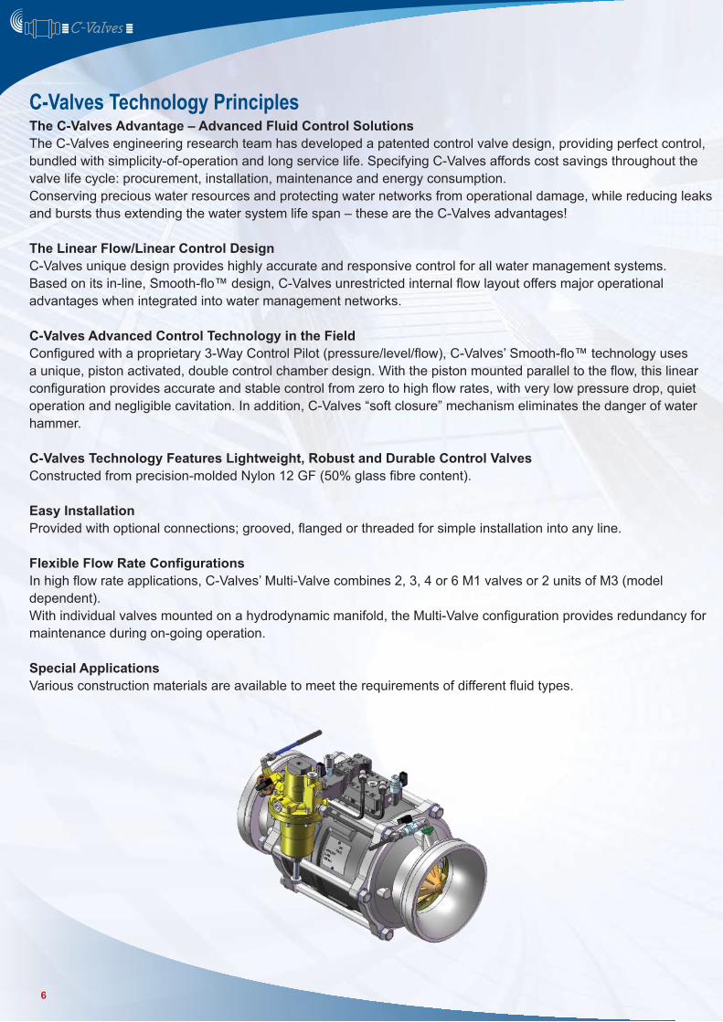
The C-Valves Advantage – Advanced Fluid Control SolutionsThe C-Valves engineering research team has developed a patented control valve design, providing perfect control, bundled with simplicity-of-operation and long service life. Specifying C-Valves affords cost savings throughout the valve life cycle: procurement, installation, maintenance and energy consumption.Conserving precious water resources and protecting water networks from operational damage, while reducing leaks and bursts thus extending the water system life span – these are the C-Valves advantages!
The Linear Flow/Linear Control Design C-Valves unique design provides highly accurate and responsive control for all water management systems.Based on its in-line, Smooth-flo™ design, C-Valves unrestricted internal flow layout offers major operational advantages when integrated into water management networks.
C-Valves Advanced Control Technology in the FieldConfigured with a proprietary 3-Way Control Pilot (pressure/level/flow), C-Valves’ Smooth-flo™ technology uses a unique, piston activated, double control chamber design. With the piston mounted parallel to the flow, this linear configuration provides accurate and stable control from zero to high flow rates, with very low pressure drop, quiet operation and negligible cavitation. In addition, C-Valves “soft closure” mechanism eliminates the danger of water hammer.
C-Valves Technology Features Lightweight, Robust and Durable Control ValvesConstructed from precision-molded Nylon 12 GF (50% glass fibre content).
Easy InstallationProvided with optional connections; grooved, flanged or threaded for simple installation into any line.
Flexible Flow Rate ConfigurationsIn high flow rate applications, C-Valves’ Multi-Valve combines 2, 3, 4 or 6 M1 valves or 2 units of M3 (model dependent).With individual valves mounted on a hydrodynamic manifold, the Multi-Valve configuration provides redundancy for maintenance during on-going operation.
Special ApplicationsVarious construction materials are available to meet the requirements of different fluid types.
C-Valves Technology Principles
6
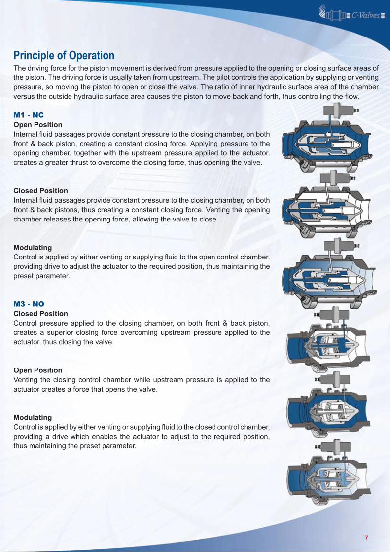
Principle of OperationThe driving force for the piston movement is derived from pressure applied to the opening or closing surface areas of the piston. The driving force is usually taken from upstream. The pilot controls the application by supplying or venting pressure, so moving the piston to open or close the valve. The ratio of inner hydraulic surface area of the chamber versus the outside hydraulic surface area causes the piston to move back and forth, thus controlling the flow.
M1 - NCOpen PositionInternal fluid passages provide constant pressure to the closing chamber, on both front & back piston, creating a constant closing force. Applying pressure to the opening chamber, together with the upstream pressure applied to the actuator, creates a greater thrust to overcome the closing force, thus opening the valve.
Closed PositionInternal fluid passages provide constant pressure to the closing chamber, on both front & back pistons, thus creating a constant closing force. Venting the opening chamber releases the opening force, allowing the valve to close.
ModulatingControl is applied by either venting or supplying fluid to the open control chamber, providing drive to adjust the actuator to the required position, thus maintaining the preset parameter.
M3 - NOClosed PositionControl pressure applied to the closing chamber, on both front & back piston, creates a superior closing force overcoming upstream pressure applied to the actuator, thus closing the valve.
Open PositionVenting the closing control chamber while upstream pressure is applied to the actuator creates a force that opens the valve.
ModulatingControl is applied by either venting or supplying fluid to the closed control chamber, providing a drive which enables the actuator to adjust to the required position, thus maintaining the preset parameter.
7
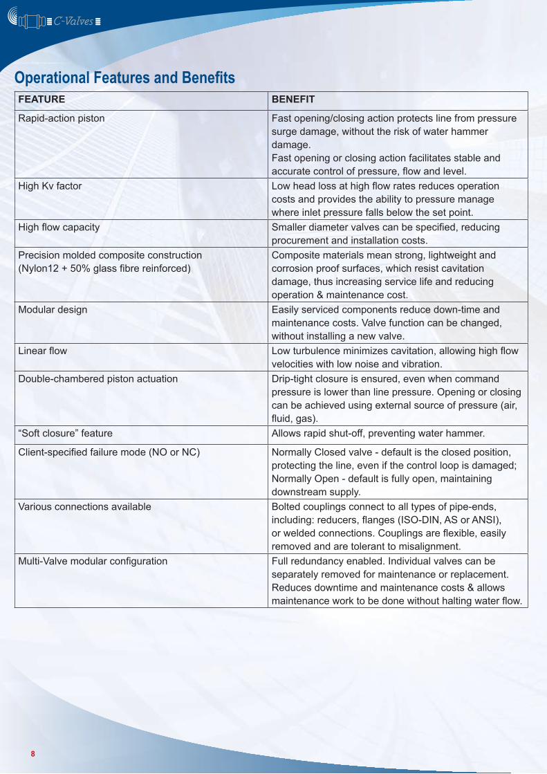
Operational Features and BenefitsFEATURE BENEFIT
Rapid-action piston Fast opening/closing action protects line from pressure surge damage, without the risk of water hammer damage.Fast opening or closing action facilitates stable and accurate control of pressure, flow and level.
High Kv factor Low head loss at high flow rates reduces operation costs and provides the ability to pressure manage where inlet pressure falls below the set point.
High flow capacity Smaller diameter valves can be specified, reducing procurement and installation costs.
Precision molded composite construction (Nylon12 + 50% glass fibre reinforced)
Composite materials mean strong, lightweight and corrosion proof surfaces, which resist cavitation damage, thus increasing service life and reducing operation & maintenance cost.
Modular design Easily serviced components reduce down-time and maintenance costs. Valve function can be changed, without installing a new valve.
Linear flow Low turbulence minimizes cavitation, allowing high flow velocities with low noise and vibration.
Double-chambered piston actuation Drip-tight closure is ensured, even when command pressure is lower than line pressure. Opening or closing can be achieved using external source of pressure (air, fluid, gas).
“Soft closure” feature Allows rapid shut-off, preventing water hammer.
Client-specified failure mode (NO or NC) Normally Closed valve - default is the closed position, protecting the line, even if the control loop is damaged; Normally Open - default is fully open, maintaining downstream supply.
Various connections available Bolted couplings connect to all types of pipe-ends, including: reducers, flanges (ISO-DIN, AS or ANSI), or welded connections. Couplings are flexible, easily removed and are tolerant to misalignment.
Multi-Valve modular configuration Full redundancy enabled. Individual valves can be separately removed for maintenance or replacement. Reduces downtime and maintenance costs & allows maintenance work to be done without halting water flow.
8
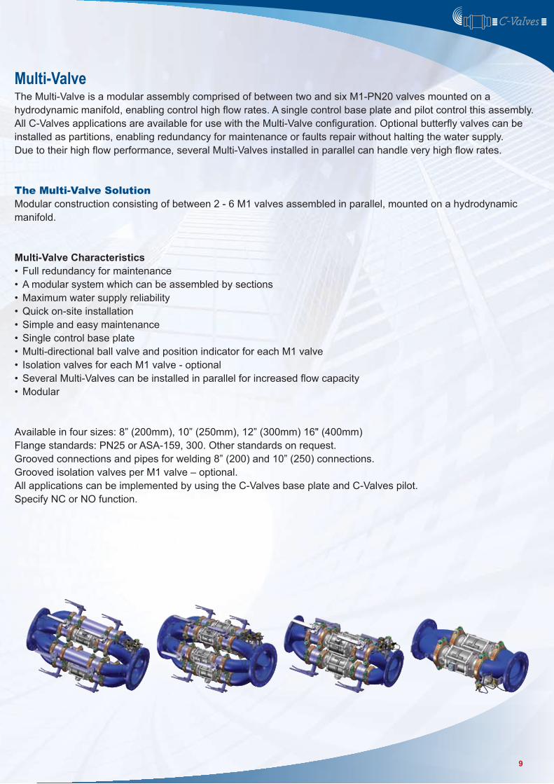
Multi-ValveThe Multi-Valve is a modular assembly comprised of between two and six M1-PN20 valves mounted on a hydrodynamic manifold, enabling control high flow rates. A single control base plate and pilot control this assembly. All C-Valves applications are available for use with the Multi-Valve configuration. Optional butterfly valves can be installed as partitions, enabling redundancy for maintenance or faults repair without halting the water supply.Due to their high flow performance, several Multi-Valves installed in parallel can handle very high flow rates.
The Multi-Valve SolutionModular construction consisting of between 2 - 6 M1 valves assembled in parallel, mounted on a hydrodynamic manifold.
Multi-Valve CharacteristicsFull redundancy for maintenanceA modular system which can be assembled by sectionsMaximum water supply reliabilityQuick on-site installationSimple and easy maintenanceSingle control base plateMulti-directional ball valve and position indicator for each M1 valveIsolation valves for each M1 valve - optionalSeveral Multi-Valves can be installed in parallel for increased flow capacityModular
Available in four sizes: 8” (200mm), 10” (250mm), 12” (300mm) 16" (400mm)Flange standards: PN25 or ASA-159, 300. Other standards on request.Grooved connections and pipes for welding 8” (200) and 10” (250) connections.Grooved isolation valves per M1 valve – optional.All applications can be implemented by using the C-Valves base plate and C-Valves pilot.Specify NC or NO function.
••••••••••
9
••••
••••
Water distribution systems are sensitive to differences in pressure throughout the network. In order to achieve stable delivery pressure over the entire system, pressure reducing valves (PRV) are employed to maintain pre-determined pressure at designated locations, thereby creating dynamic balance and reducing strain on the system components.
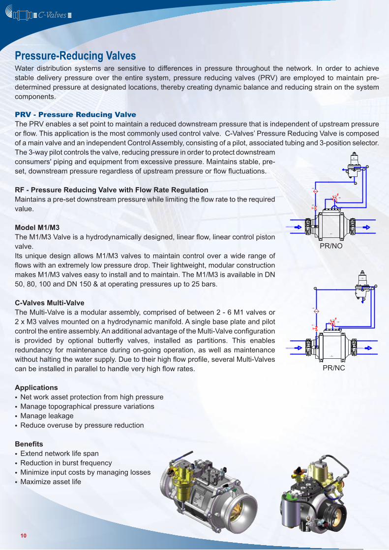
PRV - Pressure Reducing Valve The PRV enables a set point to maintain a reduced downstream pressure that is independent of upstream pressure or flow. This application is the most commonly used control valve. C-Valves’ Pressure Reducing Valve is composed of a main valve and an independent Control Assembly, consisting of a pilot, associated tubing and 3-position selector. The 3-way pilot controls the valve, reducing pressure in order to protect downstream consumers' piping and equipment from excessive pressure. Maintains stable, pre-set, downstream pressure regardless of upstream pressure or flow fluctuations.
RF - Pressure Reducing Valve with Flow Rate RegulationMaintains a pre-set downstream pressure while limiting the flow rate to the required value.
Model M1/M3The M1/M3 Valve is a hydrodynamically designed, linear flow, linear control piston valve.Its unique design allows M1/M3 valves to maintain control over a wide range of flows with an extremely low pressure drop. Their lightweight, modular construction makes M1/M3 valves easy to install and to maintain. The M1/M3 is available in DN 50, 80, 100 and DN 150 & at operating pressures up to 25 bars.
C-Valves Multi-ValveThe Multi-Valve is a modular assembly, comprised of between 2 - 6 M1 valves or 2 x M3 valves mounted on a hydrodynamic manifold. A single base plate and pilot control the entire assembly. An additional advantage of the Multi-Valve configuration is provided by optional butterfly valves, installed as partitions. This enables redundancy for maintenance during on-going operation, as well as maintenance without halting the water supply. Due to their high flow profile, several Multi-Valves can be installed in parallel to handle very high flow rates.
ApplicationsNet work asset protection from high pressureManage topographical pressure variationsManage leakage Reduce overuse by pressure reduction
BenefitsExtend network life spanReduction in burst frequencyMinimize input costs by managing lossesMaximize asset life
Pressure-Reducing Valves
10
Water distribution systems are sensitive to differences in pressure throughout the network. In order to achieve stable delivery pressure over the entire system, pressure reducing valves (PRV) are employed to maintain pre-determined pressure at designated locations, thereby creating dynamic balance and strain on the system components.
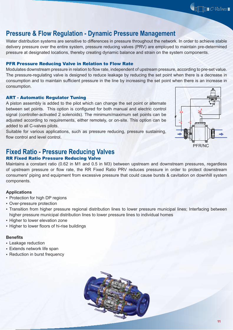
PFR Pressure Reducing Valve in Relation to Flow RateModulates downstream pressure in relation to flow rate, independent of upstream pressure, according to pre-set value. The pressure-regulating valve is designed to reduce leakage by reducing the set point when there is a decrease in consumption and to maintain sufficient pressure in the line by increasing the set point when there is an increase in consumption. ART - Automatic Regulator TuningA piston assembly is added to the pilot which can change the set point or alternate between set points. This option is configured for both manual and electric control signal (controller-activated 2 solenoids). The minimum/maximum set points can be adjusted according to requirements, either remotely, or on-site. This option can be added to all C-valves pilots.Suitable for various applications, such as pressure reducing, pressure sustaining, flow control and level control.
Fixed Ratio - Pressure Reducing ValvesRR Fixed Ratio Pressure Reducing ValveMaintains a constant ratio (0.62 in M1 and 0.5 in M3) between upstream and downstream pressures, regardless of upstream pressure or flow rate, the RR Fixed Ratio PRV reduces pressure in order to protect downstream consumers' piping and equipment from excessive pressure that could cause bursts & cavitation on downhill system components.
ApplicationsProtection for high DP regionsOver-pressure protection Transition from higher pressure regional distribution lines to lower pressure municipal lines; Interfacing between higher pressure municipal distribution lines to lower pressure lines to individual homesHigher to lower elevation zone Higher to lower floors of hi-rise buildings
BenefitsLeakage reduction Extends network life spanReduction in burst frequency
Pressure & Flow Regulation - Dynamic Pressure Management
•••
••
•••
11
Pressure Sustaining Valves/Pressure-Relief Pressure relief valves are used to protect pumps and water distribution networks by relieving dangerousover-pressure levels (off-line installation). Pressure sustaining maintains a minimum level of back-pressure to prevent pump overload and line emptying (in-line installation).
PSV Pressure Sustaining ValveMaintains constant and stable upstream pressure, regardless of downstream pressure or flow rate.
QR Quick Relief ValveMaintains the upstream pressure to ensure that pre-set value is not exceeded. Immediately vents excess line pressure from the line.
SF Pressure Sustaining Valve with Flow Rate LimitingMaintains Limits the upstream pressure from falling bellow a pre-set values while limiting the flow from exceeding a pre-set value.
Model M1/M3The M1/M3 Valve is a hydrodynamically designed, linear flow, linear control piston valve.Its unique design allows M1/M3 valves to maintain control over a wide range of flows with an extremely low pressure drop. Their lightweight, modular construction makes M1/M3 valves easy to install and to maintain. The M1/M3 is available in DN 50, 80, 100 and DN 150 & at operating pressures up to 25 bars.
C-Valves Multi-ValveThe Multi-Valve is a modular assembly, comprised of between 2 - 6 M1 valves or 2 x M3 valves mounted on a hydrodynamic manifold. A single base plate and pilot control the entire assembly. An additional advantage of the Multi-Valve configuration is provided by optional butterfly valves, installed as partitions. This enables redundancy for maintenance during on-going operation, as well as maintenance without halting the water supply. Due to their high flow profile, several Multi-Valves can be installed in parallel to handle very high flow rates.
ApplicationsPressure zones controlEnsures pump minimum flow PSVEnsures controlled pipeline fillingMaintains operating pressure for pressure vessels when discharge is to the atmosphere
BenefitsMaintains stable line pressure Protects pump from return line pressureProtects against pump overload & cavitation Prevents pipeline emptying
••••
••••
12
Sudden shutoff of a pump can create a high-pressure surge on the line, due to the ensuing pressure drop in the line. A high-pressure, high-speed surgewave of returning water can impact the closed pump check valve, with potentially damaging effect. Surge Anticipating Valves eliminate this danger by immediately reacting to pressure drops and opening before the return surge arrives, eliminating its impact on the system.
QS Surge Anticipating Control ValveProtects the system from surges and water hammer damage by relieving the water & pressure from the line (off-line installation) in the event of a sudden stop in flow (for example: in the event of a power failure). Available in a fully hydraulic configuration, or combined hydraulic and electric activation.
ApplicationsProtection of long linesProtection of network, pumps, valves and accessories
BenefitsEliminates surge in all types of pumping systems Eliminates surge in all distribution networks: Municipal, high-rise buildings, wastewater lines
Surge Anticipating Valves
••
••
13
Flow Control ValvesFlow Control Valves protect the network & accessories from damage due to excessive flow. Excessive flow in a system that exceeds the designed range can disrupt water supply and damage network facilities. Suitable for systems that require constant flow rates.
FV Flow Valve Maintains constant pre-set flow rate regardless of upstream/downstream pressure. Valve opens fully when the flow rate falls below the set point.
Model M1/M3The M1/M3 Valve is a hydrodynamically designed, linear flow, linear control piston valve.Its unique design allows M1/M3 valves to maintain control over a wide range of flows with an extremely low pressure drop. Their lightweight, modular construction makes M1/M3 valves easy to install and to maintain. The M1/M3 is available in DN 50, 80, 100 and DN 150 & at operating pressures up to 25 bars.
C-Valves Multi-ValveThe Multi-Valve is a modular assembly, comprised of between 2 - 6 M1 valves or 2 x M3 valves mounted on a hydrodynamic manifold. A single base plate and pilot control the entire assembly. An additional advantage of the Multi-Valve configuration is provided by optional butterfly valves, installed as partitions. This enables redundancy for maintenance or faults repair during on-going operation, as well as maintenance without halting the water supply. Due to their high flow profile, several Multi-Valves can be installed in parallel to handle very high flow rates.
ApplicationsControlling pressure flow conditionsEnsuring efficiency of biological & other treatment plants
BenefitsControl networks' flowLimits over-demand at set times
••
••
14
Installed on the pump discharge, this valve prevents surges by opening slowly when activated. During shut-down, the valve closes slowly, until the position indicator limit switch stops the pump.
BS Pressure Sustaining-Pump Valve (Booster)Maintains minimum pressure at the pump discharge. This prevents the pump from operating at low pressure during filling of the line. When supply voltage is cut, the valve closes immediately to prevent return flows or when the pump is stopped the valve closes softly to prevent backflow.
BV Booster ValveThis valve is installed on the pump discharge. By opening slowly upon activation, surges are prevented. During shut-down, the valve closes slowly, until the position indicator limit switch stops the pump. This valve is an active Non-Return valve.
Model M1/M3The M1/M3 Valve is a hydrodynamically designed, linear flow, linear control piston valve.Its unique design allows M1/M3 valves to maintain control over a wide range of flows with an extremely low pressure drop. Their lightweight, modular construction makes M1/M3 valves easy to install and to maintain. The M1/M3 is available in DN 50, 80, 100 and DN 150 & at operating pressures up to 25 bars.
C-Valves Multi-ValveThe Multi-Valve is a modular assembly, comprised of between 2 - 6 M1 valves or 2 x M3 valves mounted on a hydrodynamic manifold. A single base plate and pilot control the entire assembly. An additional advantage of the Multi-Valve configuration is provided by optional butterfly valves, installed as partitions. This enables redundancy for maintenance or faults repair during on-going operation, as well as maintenance without halting the water supply. Due to their high flow profile, several Multi-Valves can be installed in parallel to handle very high flow rates.
ApplicationsProtects lines & pumps from surges or extreme operating conditionsPump start-and-stop in varied combinations
Booster Pump Control Valves
••
15
Modern water distribution networks depend on quick-reacting and highly accurate electronically-controlled valves. These valves provide operators with the ability to control the network parameters in real-time, using valves as individual components, or in mutually dependent control applications.
A valve that is installed at the inlet or outlet of a reservoir & provides accurate control of the required pre-set levels. Easy to install and maintain, these valves provide accurate control without the installation and maintain, issues that are common with mechanical float valves.
AV Altitude (Level Pressure) ValveMaintains a constant level in the pool/reservoir/tank. The valve is located on the filling or emptying line, eliminating the need to install reservoir accessories.The valve is controlled by a sensitive 3-way pilot.
SV Pressure Sustaining-Float Valve (Two Level)Maintains upstream pressure while filling or emptying a pool/reservoir/tank.
VH 3-way Hydraulic Pool Valve (Two Level)Maintains the level in the pool / reservoir / tank within a pre-set range. The valve is located on the filling or emptying line and is controlled by a 3-way or 4-ways float valve. The valve is available with a four-wayfloat valve and can be fitted with a "soft closure" function to eliminate water hammer.
ApplicationsFilling or empting a reservoirFor lines with low supply-pressureDistribution directing lines
BenefitsQuiet & smooth operation Reduces energy consumption
•••
••
Reservoir & Level Control Valves
16
Three-way Hydraulic Pool ValveVF Two-way Hydraulic Pool Valve Maintains a constant level in the pool/reservoir/tank. The valve is located on the filling or emptying line and is controlled by a 2way float valve.
Pool Valve with Electric Control (EF) (Two Level)
FW – Four way hydraulic pool valveMaintains pool level within the required range – the valve is located either at the filling or emptying line.
Model M1/M3The M1/M3 Valve is a hydrodynamically designed, linear flow, linear control piston valve.Its unique design allows M1/M3 valves to maintain control over a wide range of flows with an extremely low pressure drop. Their lightweight, modular construction makes M1/M3 valves easy to install and to maintain. The M1/M3 is available in DN 50, 80, 100 and DN 150 & at operating pressures up to 25 bars.
C-Valves Multi-ValveThe Multi-Valve is a modular assembly, comprised of between 2 - 6 M1 valves or 2 x M3 valves mounted on a hydrodynamic manifold. A single base plate and pilot control the entire assembly. An additional advantage of the Multi-Valve configuration is provided by optional butterfly valves, installed as partitions. This enables redundancy for maintenance or faults repair during on-going operation, as well as maintenance without halting the water supply. Due to their high flow profile, several Multi-Valves can be installed in parallel to handle very high flow rates.
ApplicationsRe-circulating & refreshing of reservoirsFilling up a reservoirFor lines with low supply-pressureDistribution directing lines
BenefitsPreventing reservoir overflow Optimizing water level managementQuiet & smooth operation Reduces energy consumption
••••
••••
17
Security ValveA terrorist mega-attack on closed water reservoirs might include sabotage of the reservoir control valves to force them to remain open. Although the security system may give an alarm and send a closing signal to the valve, the contaminated water would continue to flow to unsuspecting customers. Water poisoning could lead to unprecedented disaster.
The security valve will prevent contaminated water from entering the network, averting the potentially devastating results of such an attack (death and illness), as well as a major cleanup operation.
The system is comprised of a single M1 Valve or a Multi-Valve assembly consisting of between one and six M1 valves, mounted on a hydrodynamic manifold. The number of valves in a Multi-Valve assembly is determined by the system requirements: maximum flow rates and permitted head-losses.Closing of the valve is effected by in-line pressure, one of the unique qualities of C-Valves’ N.C. valve. The closing motion is aided by a spring, allowing closure even when there is no pressure in the line.
Accumulator Pressure Tank - Supplies pressure to open the valve and allows full opening even when there is no pressure in the line.
Control Cabinet - The electric valve that operates the M1 valve and its electronic operation system are located within a secured and locked stainless steel box, so that any attempted sabotage or vandalism will automatically close the valve. The connection to the system control module is elctrical wires that, when disconnected, will cause the valve to close, with no possibility of bypass.
Position Indicator – Indicates the valve opening percentage and transmits a signal to the control system when the valve is closed.
Operating Pressure Range: 0.5 - 25 bar.
Opening: Enabled by the accumulator pressure tank. The tank is equipped with a pressure switch that warns when pressure drops below the set point, allowing sufficient time to replace the tank.If the line pressure is higher than 3 bars, the line pressure will fully open the valve (without using the tank supply).
Closing: The valve closes at any pressure (including zero pressure) and does not require the use of external pressure.The valve is an NC type that comes with a “failsafe to close” feature that guarantees valve closure in the event of failure.The valve is double chambered, enabling opening by an external pressure source, and can be closed regardless of the reservoir level.The valve actuator is located at the center of the valve, surrounded by the water flow, and cannot be accessed from the outside (in contrast to other valves, where the actuator is located outside the valve body and the operation chambers are exposed to bypass attempts).
18
Opening and closing response timesValve opening and closing times are within the range of 2.5 – 10 seconds, depending on the line pressure and the diameter of the valve.
Maximum flow rate under protracted working conditionsSingle M1 valve – 550 m3/h8” Multi-Valve – 1000 m3/h12” Multi-Valve – 2000 m3/h16” Multi-Valve – 3000 m3/h
Characterized closingThe valve is characterized by a slowed rate of closing towards the end of the closing action, thus minimizing water surge phenomena.
Operating temperature rangeThe fluid operating temperature in the line is 4oC – 60oC.
BenefitsPrevent contaminated water from entering the water networkProtect population from hostile threats to drinking water sourcesPrevent major cleanup operation
•••
19
Water systems are vulnerable to bursts, whether due to hydraulic conditions, topography or external mechanical damage. Burst Control Valves isolate the damaged zone until manually reset, minimizing water wastage, and other possible damages.
HF Burst Valve Valve shuts off when the flow rate exceeds a pre-set value, for example, because of a burst line. The valve can only be re-opened by manual activation.
Model M1/M3The M1/M3 Valve is a hydrodynamically designed, linear flow, linear control piston valve.Its unique design allows M1/M3 valves to maintain control over a wide range of flows with an extremely low pressure drop. Their lightweight, modular construction makes M1/M3 valves easy to install and to maintain. The M1/M3 is available in DN 50, 80, 100 and DN 150 & at operating pressures up to 25 bars.
C-Valves Multi-ValveThe Multi-Valve is a modular assembly, comprised of between 2 - 6 M1 valves or 2 x M3 valves mounted on a hydrodynamic manifold. A single base plate and pilot control the entire assembly. An additional advantage of the Multi-Valve configuration is provided by optional butterfly valves, installed as partitions. This enables redundancy for maintenance or faults repair during on-going operation, as well as maintenance without halting the water supply. Due to their high flow profile, several Multi-Valves can be installed in parallel to handle very high flow rates.
ApplicationsZone shut-off High risk networks - high leakage networksReservoir outlets in earthquake risk areas
BenefitsProtects networks with mechanical weaknesses
Burst Control Valve
•••
•
20
Technical DataM1 Series:DN100 – DN150DN200 – DN400 in a Multi-valve application – a manifold with two, three, four or six valves controlled by one pilot.M1 Adjustable inlets and outlets for different pipe diameters with various connections to line.M3 Series:DN50 – DN80DN80 – in a Multi-valve application – a manifold with two units controlled by one pilot.M3 Adjustable inlets and outlets for different pipe diameters with various connections to line.
Materials:
M1 Operating Pressure Range:
M3 Operating Pressure Range:
• Can be supplied with different structural materials for various applications, Polypropylene products are in stock.
• Minimum required pressure for operation – 1.2 bars.
Part Material
M-1 M-3Valve bodies, pistons, bushings, front and rear cups
Reinforced fiberglass nylon or Polypropylene Reinforced fiberglass nylon or Polypropylene
Main seal NBR, VITON or EPDM rubber, Shore index: 80 NBR, VITON or EPDM rubber, Shore index: 80
O-rings NBR or EPDM rubber, Shore index: 70 NBR or EPDM rubber, Shore index: 70
Inlets, outlets Stainless steel 316 Reinforced fiberglass nylon
Inlets, outlets Stainless steel 316 Reinforced fiberglass nylon Clamps, bolts Stainless steel Stainless steel 316Metal envelope (for high pressure) Spheroid iron with polyester or epoxy coating or
stainless steel 316N/A
Multi-Valve manifolds Spheroid iron with polyester or epoxy coating or stainless steel 316
Spheroid iron with polyester or epoxy coating
PN Model Max pressure
PN 16 Plastic model with clamps 16 barsPN 20 Plastic model with stud bolts 20 barsPN 25 Plastic model with metal casing 25 barsPN 30 Plastic model with metal casing and stud bolts 30 bars
PN Model Max pressure
PN 25 Plastic model with clamps 25 bars
21
M1 Opening / Closing Parameters Minimum (meters):
M3 Opening Parameters Minimum (meters):
M1 - Minimal Opening & Closing PressureModel Closing (meters) Opening (meters) Full Opening (meters)NO 6 2 3NO with spring 5 2 6NC 14 2 7NC with spring 3 3 20
M3 - Minimal Opening & Closing PressureModel Closing (meters) Opening (meters) Full Opening (meters)NO 10 4 7
C-Valves Head Loss Chart
-------M3 ------- M1------- DN-200 ------- DN-250 ------- DN-300 ------- DN-400
BAR1.00
10 20 30 40 50 200 300 400 500 1000 2000
KV=90 KV=435 KV=850 KV=1570KV=2500KV=1210
3000 5000 1000100
0.500.400.30
0.20
0.10
0.050.040.03
0.01
NotesIf downstream pressure is lower than 20 meters and in cases of very high flow rates, please consult with C-Valves applications department.The closing pressure can be reduced at the expense of the opening pressure.
Booster Pressure:NO model also closes when the control pressure is 85% of line pressure.NC model also opens fully when the control pressure is 80% of the line pressure (opening begins at 25%).
Temperature Range: Operating temperatures from 4oC – 60oC.
22
Operation ParametersOn-Off Valves:
Regulating Valves (Pressure Reducing, Pressure Sustaining, Flow Regulator): Use the sizing chart for the required valve size:
• M3 DN50 is designed to operate from 0 to 80 m3/h, Kv= 90• M3 DN80 is designed to operate from 0 to 120 m3/h, Kv=90• M1 DN100 is designed to operate from 0 to 250 m3/h, Kv=435• M1 DN150 is designed to operate from 0 to 550 m3/h, Kv=435• DN200 Multi-Valve (2 M1 PN20 valves) is designed to operate from 0 to 1000 m3/h. Kv=850• DN250 Multi-Valve (3 M1 valves, or less) is designed operate from 0 to 1500 m3/h, Kv=1210• DN300 Multi-Valve (4 M1 valves, or less) is designed operate from 0 to 2000 m3/h. Kv=1570• DN400 Multi-Valve (6 M1 valves or less) is designed for operating from 0 to 3000 m3/h. Kv=2500
M3-DN50 M3-DN80 M1-DN100 M1-DN150 MV-DN200 MV-DN250 MV-DN300 MV-DN400
Flow (M3/h)
Flow (M3/h)
23
22
21
20
19
18
17
16
15
14
13
12
11
10
9
8
7
6
5
4
3
2
1500 450 400 350 300 250 200 150 100 50 0
LOW FLOW
3000 2900 2800 2700 2600 2500 2400 2300 2200 2100 2000 1900 1800 1700 1600 1500 1400 1300 1200 1100 1000 900 800 700 600 500
12
11
10
9
8
7
6
5
4
3
2
1
HIGH FLOW
23
Valve Diameter (mm)
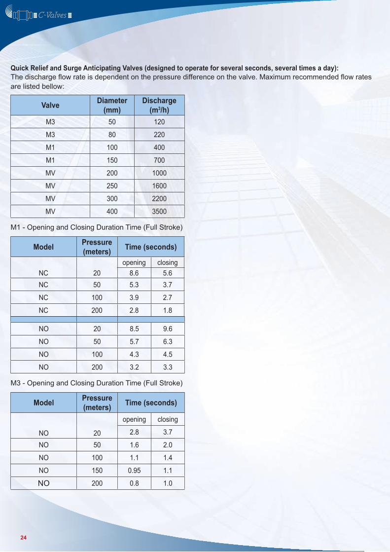
Discharge (m3/h)
M3 50 120
M3 80 220
M1 100 400
M1 150 700
MV 200 1000
MV 250 1600
MV 300 2200
MV 400 3500
Model Pressure (meters) Time (seconds)
NO 20
opening closing
2.8 3.7
NO 50 1.6 2.0
NO 100 1.1 1.4
NO 150 0.95 1.1
NO 200 0.8 1.0
NO 20 8.5 9.6
NO 50 5.7 6.3
NO 100 4.3 4.5
NO 200 3.2 3.3
Quick Relief and Surge Anticipating Valves (designed to operate for several seconds, several times a day):The discharge flow rate is dependent on the pressure difference on the valve. Maximum recommended flow rates are listed bellow:
M1 - Opening and Closing Duration Time (Full Stroke)
M3 - Opening and Closing Duration Time (Full Stroke)
Model Pressure (meters) Time (seconds)
NC 20opening closing
8.6 5.6NC 50 5.3 3.7
NC 100 3.9 2.7
NC 200 2.8 1.8
24
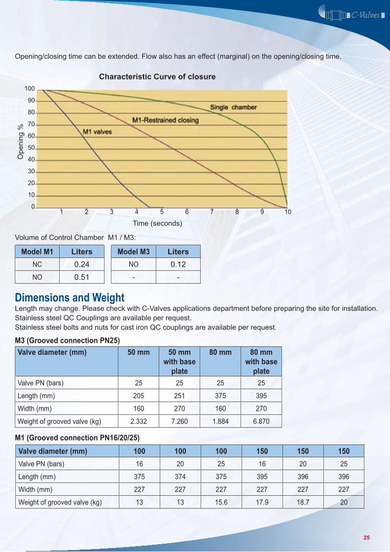
Opening/closing time can be extended. Flow also has an effect (marginal) on the opening/closing time.
Characteristic Curve of closure
Volume of Control Chamber M1 / M3:
Length may change. Please check with C-Valves applications department before preparing the site for installation.Stainless steel QC Couplings are available per request.Stainless steel bolts and nuts for cast iron QC couplings are available per request.
1 2 3 4 5 6 7 8 9
100
90
80
70
60
50
40
30
20
10
0
Time (seconds)
Ope
ning
%
10
Model M1 LitersNC 0.24NO 0.51
Model M3 LitersNO 0.12
- -
Dimensions and Weight
Valve diameter (mm) 50 mm 50 mm with base
plate
80 mm 80 mm with base
plateValve PN (bars) 25 25 25 25
Length (mm) 205 251 375 395
Width (mm) 160 270 160 270
Weight of grooved valve (kg) 2.332 7.260 1.884 6.870
Valve diameter (mm) 100 100 100 150 150 150Valve PN (bars) 16 20 25 16 20 25
Length (mm) 375 374 375 395 396 396
Width (mm) 227 227 227 227 227 227
Weight of grooved valve (kg) 13 13 15.6 17.9 18.7 20
M3 (Grooved connection PN25)
M1 (Grooved connection PN16/20/25)
25
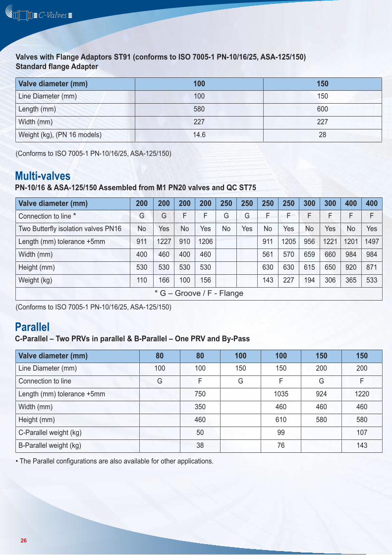
Valve diameter (mm) 100 150Line Diameter (mm) 100 150
Length (mm) 580 600
Width (mm) 227 227
Weight (kg), (PN 16 models) 14.6 28
Valve diameter (mm) 200 200 200 200 250 250 250 250 300 300 400 400Connection to line * G G F F G G F F F F F F
Two Butterfly isolation valves PN16 No Yes No Yes No Yes No Yes No Yes No Yes
Length (mm) tolerance +5mm 911 1227 910 1206 911 1205 956 1221 1201 1497
Width (mm) 400 460 400 460 561 570 659 660 984 984
Height (mm) 530 530 530 530 630 630 615 650 920 871
Weight (kg) 110 166 100 156 143 227 194 306 365 533
* G – Groove / F - Flange
Valve diameter (mm) 80 80 100 100 150 150Line Diameter (mm) 100 100 150 150 200 200
Connection to line G F G F G F
Length (mm) tolerance +5mm 750 1035 924 1220
Width (mm) 350 460 460 460
Height (mm) 460 610 580 580
C-Parallel weight (kg) 50 99 107
B-Parallel weight (kg) 38 76 143
Valves with Flange Adaptors ST91 (conforms to ISO 7005-1 PN-10/16/25, ASA-125/150)Standard flange Adapter
(Conforms to ISO 7005-1 PN-10/16/25, ASA-125/150)
(Conforms to ISO 7005-1 PN-10/16/25, ASA-125/150)
• The Parallel configurations are also available for other applications.
Multi-valves
Parallel
PN-10/16 & ASA-125/150 Assembled from M1 PN20 valves and QC ST75
C-Parallel – Two PRVs in parallel & B-Parallel – One PRV and By-Pass
26
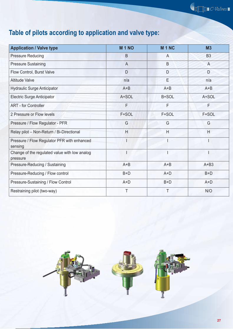
Table of pilots according to application and valve type:
Application / Valve type M 1 NO M 1 NC M3Pressure Reducing B A B3
Pressure Sustaining A B A
Flow Control, Burst Valve D D D
Altitude Valve n/a E n/a
Hydraulic Surge Anticipator A+B A+B A+B
Electric Surge Anticipator A+SOL B+SOL A+SOL
ART - for Controller F F F
2 Pressure or Flow levels F+SOL F+SOL F+SOL
Pressure / Flow Regulator - PFR G G G
Relay pilot – Non-Return / Bi-Directional H H H
Pressure / Flow Regulator PFR with enhanced sensing
I I I
Change of the regulated value with low analog pressure
I I I
Pressure-Reducing / Sustaining A+B A+B A+B3
Pressure-Reducing / Flow control B+D A+D B+D
Pressure-Sustaining / Flow Control A+D B+D A+D
Restraining pilot (two-way) T T N/O
27
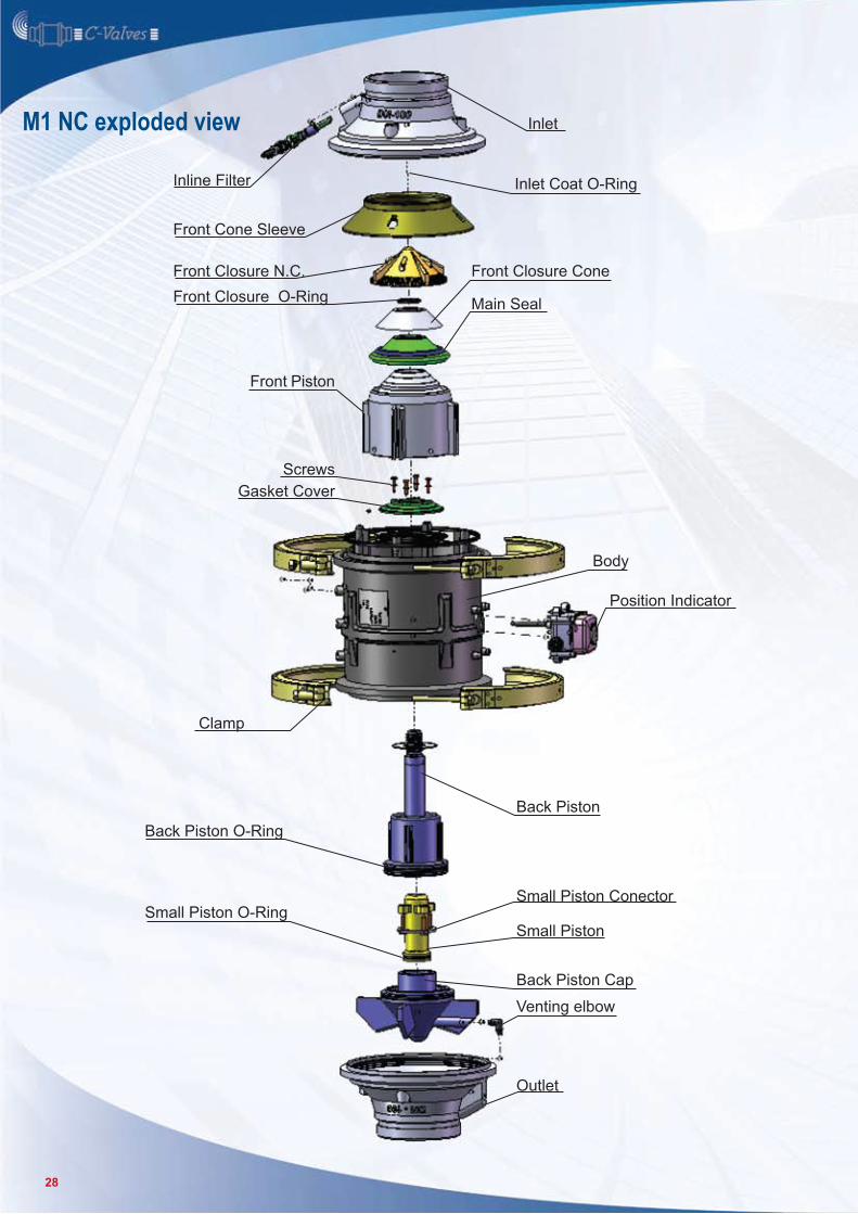
M1 NC exploded view Inlet
Front Closure O-Ring
Inlet Coat O-Ring
Front Closure Cone
Main Seal
Front Closure N.C.
Front Cone Sleeve
Body
Position Indicator
ScrewsGasket Cover
Back Piston
Front Piston
Inline Filter
Clamp
Small Piston Conector
Small Piston
Back Piston Cap
Venting elbow
Outlet
Small Piston O-Ring
Back Piston O-Ring
28
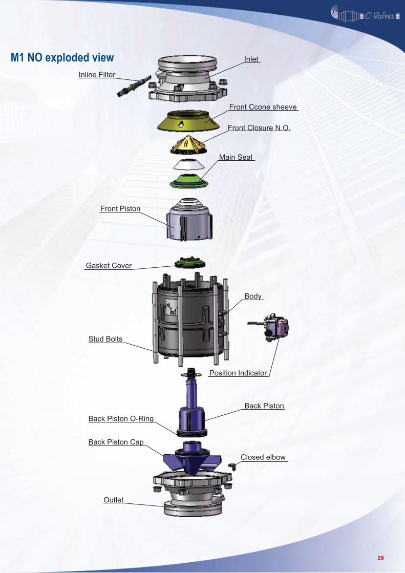
M1 NO exploded view Inlet
Main Seal
Front Closure N.O.
Front Ccone sheeve
Gasket Cover
Back Piston
Position Indicator
Front Piston
Inline Filter
Back Piston Cap
Back Piston O-Ring
Stud Bolts
Closed elbow
Outlet
Body
29
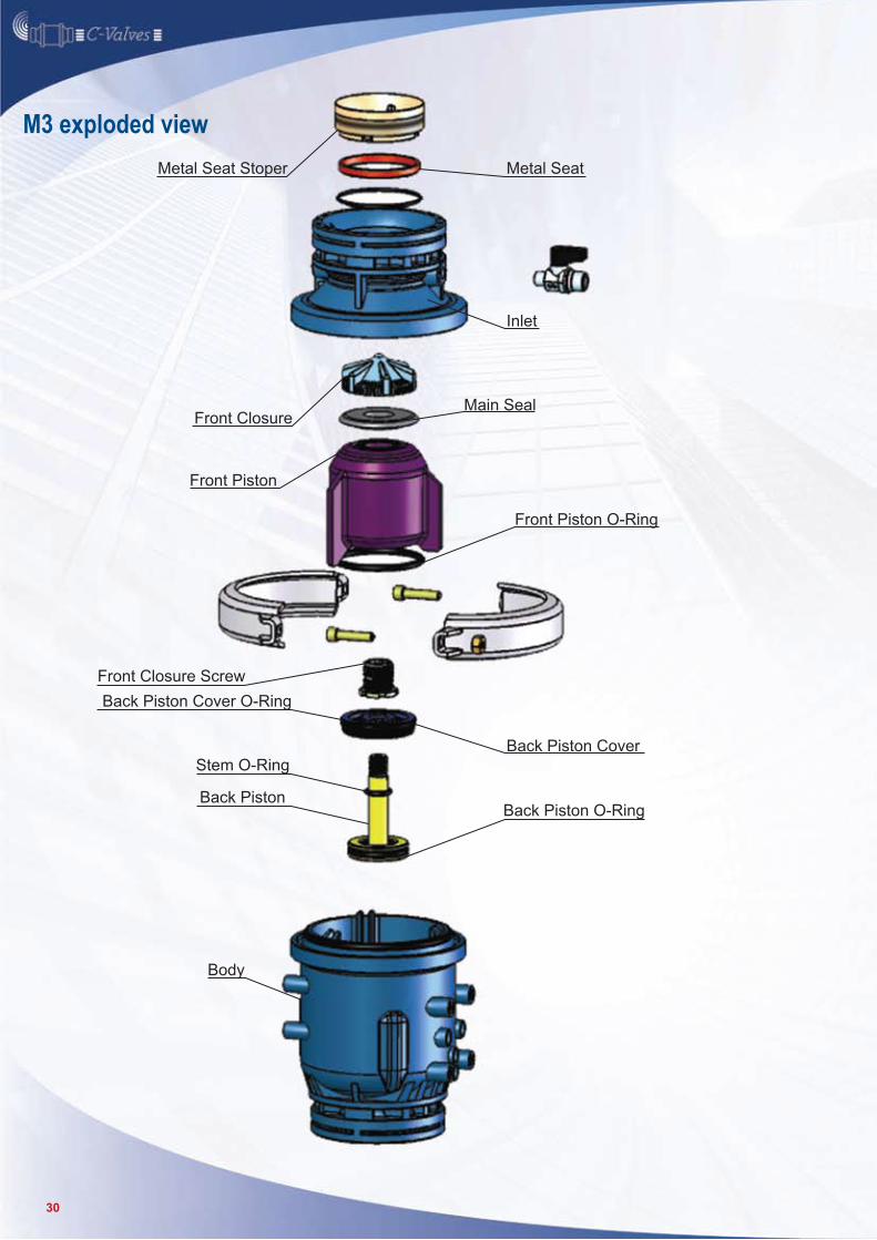
M3 exploded view
Inlet
Main Seal
Back Piston Cover
Back Piston O-Ring
Metal SeatMetal Seat Stoper
Front Closure
Front Closure Screw
Front Piston
Body
Back Piston Cover O-Ring
Back Piston
Stem O-Ring
Front Piston O-Ring
30