Embed Size (px)
Citation preview
Servo solenoid valves with electrical position feedback (Lvdt DC/DC ±10V)
Type 4WRPH6
RE 29028/01.05 1/10
Replaces: 09.03
Size 6Unit series 2XMaximum working pressure P, A, B 315 bar, T 250 barNominal flow rate 2...40 l/min (∆p 70 bar)
List of contents
Contents Page
Features 1
Ordering data and scope of delivery 2
Preferred types 2
Function, sectional diagram 3
Symbols 3
Technical data 4
Valve with external trigger electronics 5 and 6
Performance curves 7 and 8
Unit dimensions 9
Features
– Directly operated servo solenoid valve NG6, with control pistonand sleeve in servo quality
– Actuated on one side, 4/4 fail-safe position when switched off
– Control solenoid with integral position feedback andelectronics for position transducer (Lvdt DC/DC)
– Suitable for electrohydraulic controllers in production andtesting systems
– For subplate attachment, mounting hole configuration to ISO 4401-03-02-0-94
– Subplates as per catalogue section RE 45053 (order separately)
– Line sockets to DIN 43560-AM2Solenoid 2P+PE/M16x1.5, position transducer 4P/Pg7in scope of delivery, see catalogue section RE 08008
– External trigger electronics (order separately) Electric amplifier for standard curve “L”
0 811 405 060, see catalogue section RE 30041 Electric amplifier for non-linear curve “P”
40 % – 0 811 405 065 and 60 % – 0 811 405 066,see catalogue section RE 30040
Variants on request
– For standard applications
– Special symbols for plastic machines
– Sturdy “ruggedized” version for applications up to 40 g, valve with metal cap and central plug (7P).C
ourt
esy
of CM
A/F
lodyn
e/H
ydra
dyn
e
Motion C
ontr
ol
Hyd
raulic
P
neu
mat
ic
Ele
ctrica
l
Mec
han
ical
(
800)
426-5
480
ww
w.c
maf
h.c
om
4WRP H 6 B –2X/G24 Z4/ M *
A B
P T
a 0 b
2/10 Bosch Rexroth AG Industrial Hydraulics Type 4WRPH6 RE 29028/01.05
Ordering data and scope of delivery
For external
trigger eletronics = no desig.
Control piston/sleeve = H
Size 6 = 6
Symbols
4/4-way version
= C3, C5
= C4, C1
With symbols C5 and C1: 3)
P A: qv B T: qv/2
P B: qv/2 A T: qv
Side of inductive position tranducer
(Standard) = B
1) Only in connection with flow characteristic “p”2) Kink 60% for NG6 with nominal flow rate “15”
and “25”, otherwise kink 40%3) qv 2:1 only with nominal flow rate = 40 l/min
Further information
in plain text
M = NBR seals,
suitable for mineral oils
(HL, HLP) to DIN 51524
Electronical connection
Z4 = with line socket, with plug to
DIN 43560-AM2
Line socket in scope of delivery
Voltage supply of trigger electronics
G24 = +24V DC
2X = Unit series 20 to 29
(installation and connection dimensions unchanged)
Flow characteristic
L = Linear
P = Non-linear curve 2)
Nominal flow rate at 70 bar valve pressure difference
(35 bar /metering notch)
Size 6
02 = 2 l/min
04 = 4 l/min
12 = 12 l/min
15 1) = 15 l/min
24 = 24 l/min
25 1) = 25 l/min
40 3) = 40 l/min
Preferred types (available at short notice)
Type 4WRPH6 Material no.
C3/C5
4WRPH 6 C3B02L –2X/G24Z4 /M 0 811 404 041
4WRPH 6 C3B04L –2X/G24Z4 /M 0 811 404 033
4WRPH 6 C3B12L –2X/G24Z4 /M 0 811 404 034
4WRPH 6 C3B24L –2X/G24Z4 /M 0 811 404 035
4WRPH 6 C3B40L –2X/G24Z4 /M 0 811 404 036
4WRPH 6 C5B40L –2X/G24Z4 /M 0 811 404 510
4WRPH 6 C3B15P –2X/G24Z4 /M 0 811 404 047
4WRPH 6 C3B25P –2X/G24Z4 /M 0 811 404 043
4WRPH 6 C3B40P –2X/G24Z4 /M 0 811 404 044
4WRPH 6 C5B40P –2X/G24Z4 /M 0 811 404 511
Type 4WRPH6 Material no.
C1/C4
4WRPH 6 C4B02L –2X/G24Z4 /M 0 811 404 512
4WRPH 6 C4B04L –2X/G24Z4 /M 0 811 404 160
4WRPH 6 C4B12L –2X/G24Z4 /M 0 811 404 037
4WRPH 6 C4B24L –2X/G24Z4 /M 0 811 404 038
4WRPH 6 C4B40L –2X/G24Z4 /M 0 811 404 039
4WRPH 6 C1B40L –2X/G24Z4 /M 0 811 404 513
4WRPH 6 C4B15P –2X/G24Z4 /M 0 811 404 048
4WRPH 6 C4B25P –2X/G24Z4 /M 0 811 404 045
4WRPH 6 C4B40P –2X/G24Z4 /M 0 811 404 046
4WRPH 6 C1B40P –2X/G24Z4 /M 0 811 404 162
A B
P T
a 0 b
Court
esy
of CM
A/F
lodyn
e/H
ydra
dyn
e
Motion C
ontr
ol
Hyd
raulic
P
neu
mat
ic
Ele
ctrica
l
Mec
han
ical
(
800)
426-5
480
ww
w.c
maf
h.c
om
RE 29028/01.05 Type 4WRPH6 Industrial Hydraulics Bosch Rexroth AG 3/10
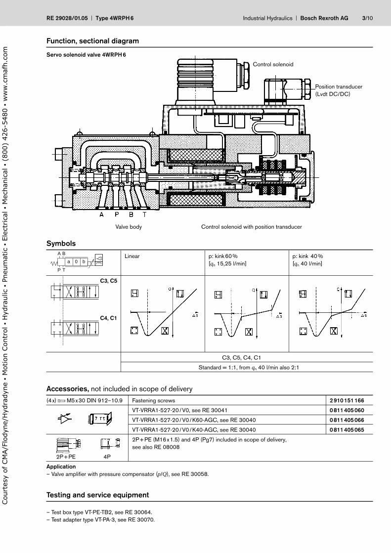
Function, sectional diagram
Symbols
Accessories, not included in scope of delivery
(4x) f M5x30 DIN 912–10.9 Fastening screws 2910151166
VT-VRRA1-527-20/V0, see RE 30041 0811405060
VT-VRRA1-527-20/V0/K60-AGC, see RE 30040 0811405066
VT-VRRA1-527-20/V0/K40-AGC, see RE 30040 0811405065
2P+PE (M16x1.5) and 4P (Pg7) included in scope of delivery,
see also RE 08008
2P+PE 4P
Application
– Valve amplifier with pressure compensator (p/Q), see RE 30058.
Servo solenoid valve 4WRPH6
Valve body
Control solenoid
Linear p: kink60% p: kink 40%
[qn 15,25 l/min] [qn 40 l/min]
C3, C5
C4, C1
C3, C5, C4, C1
Standard = 1:1, from qn 40 l/min also 2:1
A B
P T
a 0 b
Position transducer
(Lvdt DC/DC)
Control solenoid with position transducer
Testing and service equipment
– Test box type VT-PE-TB2, see RE 30064.
– Test adapter type VT-PA-3, see RE 30070.
Court
esy
of CM
A/F
lodyn
e/H
ydra
dyn
e
Motion C
ontr
ol
Hyd
raulic
P
neu
mat
ic
Ele
ctrica
l
Mec
han
ical
(
800)
426-5
480
ww
w.c
maf
h.c
om
4/10 Bosch Rexroth AG Industrial Hydraulics Type 4WRPH6 RE 29028/01.05
Technical Data
General
Construction Spool type valve, operated directly, with steel sleeve
Actuation Proportional solenoid with position control, external amplifier
Type of mounting Subplate, mounting hole configuration NG6 (ISO 4401-03-02-0-94)
Installation position Optional
Ambient temperature range °C –20…+50
Weight kg 2.3
Vibration resistance, test condition Max. 25 g, shaken in 3 dimensions (24h)
Hydraulic (measured with HLP 46, ϑoil = 40°C ±5°C)
Pressure fluid Hydraulic oil to DIN 51524 … 535, other fluids after prior consultation
Viscosity range recommended mm2/s 20…100
max. permitted mm2/s 10…800
Pressure fluid temperature range °C –20…+80
Maximum permissible degree of Class 18/16/131)
contamination of pressure fluid
Purity class to ISO 4406 (c)
Flow direction See symbol
Nominal flow at l/min 2 4 12 15 24 40
∆p = 35 bar per notch 2)
Max. working pressure bar Port P, A, B: 315
Max. pressure bar Port T: 250
Operating limits at ∆p bar <315 <315 <315 <315 <315 <160
Pressure drop at valve
qVnom: > qN valves bar <315 <315 <315 <280 <250 <100
Leakage cm3/min <150 <180 <300 <15– <500 <900
at 100 bar
cm3/min <15– <15– <15– <180 <300 < 450
Electrical
Cyclic duration factor % 100 ED
Power supply 24 Vnom (external amplifier)
Degree of protection IP 65 to DIN 40050
Solenoid connector Connector DIN 43650/ISO 4400 M16x1.5 (2P+PE)
Position transducer connector Special Connector Pg7 (4P)
Max. solenoid current A 2.7
Coil restistance R20 Ω 2.5
Max. power consumption at 100% load VA 40
and operational temperature
Position transducer Supply: +15 V/35 mA Signal: 0...±10 V (RL 10 kΩ)
DC/DC technology Supply: –15 V/35 mA
Static/Dynamic
Hysteresis % 0.2
Manufacturing tolerance for qmax. % 10
Response time for signal change ms 10
0…100%
Thermal drift Zero point displacement 1% at ∆T = 40°C
1) The purity classes stated for the components must be complied with in hydraulic systems. Effective filtration prevents problems and
also extends the service life of components. For a selection of filters, see catalogue sections RE 50070, RE 50076 and RE 50081.2) Durchfluss bei anderem ∆p ∆px2) Flow rate at a different ∆p qx = qnom ·
35
Court
esy
of CM
A/F
lodyn
e/H
ydra
dyn
e
Motion C
ontr
ol
Hyd
raulic
P
neu
mat
ic
Ele
ctrica
l
Mec
han
ical
(
800)
426-5
480
ww
w.c
maf
h.c
om
RE 29028/01.05 Type 4WRPH6 Industrial Hydraulics Bosch Rexroth AG 5/10
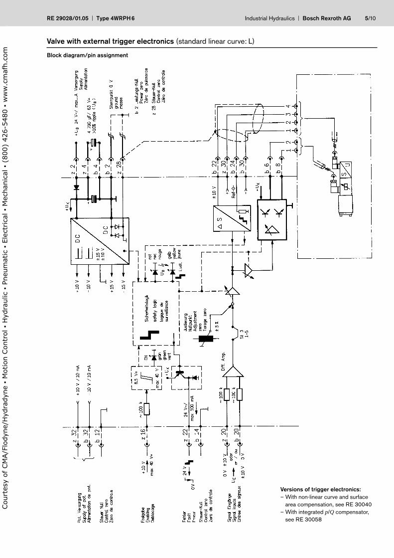
Valve with external trigger electronics (standard linear curve: L)
Block diagram/pin assignment
Versions of trigger electronics:
– With non-linear curve and surface
area compensation, see RE 30040
– With integrated p/Q compensator,
see RE 30058
Court
esy
of CM
A/F
lodyn
e/H
ydra
dyn
e
Motion C
ontr
ol
Hyd
raulic
P
neu
mat
ic
Ele
ctrica
l
Mec
han
ical
(
800)
426-5
480
ww
w.c
maf
h.c
om
6/10 Bosch Rexroth AG Industrial Hydraulics Type 4WRPH6 RE 29028/01.05
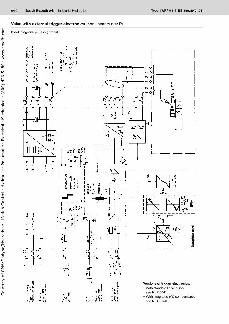
Valve with external trigger electronics (non-linear curve: P)
Block diagram/pin assignment
Versions of trigger electronics:
– With standard linear curve,
see RE 30041
– With integrated p/Q compensator,
see RE 30058
Da
ug
hte
r ca
rd
Court
esy
of CM
A/F
lodyn
e/H
ydra
dyn
e
Motion C
ontr
ol
Hyd
raulic
P
neu
mat
ic
Ele
ctrica
l
Mec
han
ical
(
800)
426-5
480
ww
w.c
maf
h.c
om
RE 29028/01.05 Type 4WRPH6 Industrial Hydraulics Bosch Rexroth AG 7/10
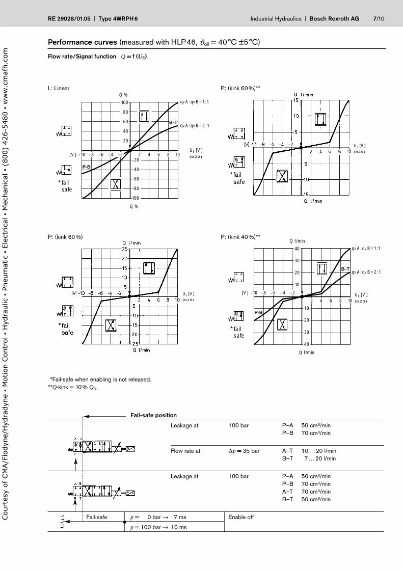
Performance curves (measured with HLP46, ϑoil = 40°C ±5°C)
Flow rate/Signal function Q = f (UE)
*Fail-safe when enabling is not released.
**Q-kink = 10% QN.
100
80
60
40
20
-20
-40
-60
-80
-100
Q %
* failsafe
Q %
L: (Linear)
-10[V]UE [V](b20)-8 -6 -4 -2 2 4 6 8 10
qVA:qVB=1:1
qVA:qVB=2:1
P-B
B-T
UE [V](b20)
40
30
20
10
10
20
30
40
P-B
B-T
-10[V] -8 -6 -4 -2
2 4 6 8 10
* failsafe
Q l/min
Q l/min
P: (Knick 40 %)qVA:qVB=1:1
qVA:qVB=2:1
UE [V](b20)
UE [V](b20)
L: Linear P: (kink 60%)**
P: (kink 60%) P: (kink 40%)**
Fail-safe position
Leakage at 100 bar P–A 50 cm3/min
P–B 70 cm3/min
Flow rate at ∆p = 35 bar A–T 10…20 l/min
B–T 7…20 l/min
Leakage at 100 bar P–A 50 cm3/min
P–B 70 cm3/min
A–T 70 cm3/min
B–T 50 cm3/min
Fail-safe p = 100 bar → 7 ms Enable off
p = 100 bar → 10 ms•C
ourt
esy
of CM
A/F
lodyn
e/H
ydra
dyn
e
Motion C
ontr
ol
Hyd
raulic
P
neu
mat
ic
Ele
ctrica
l
Mec
han
ical
(
800)
426-5
480
ww
w.c
maf
h.c
om
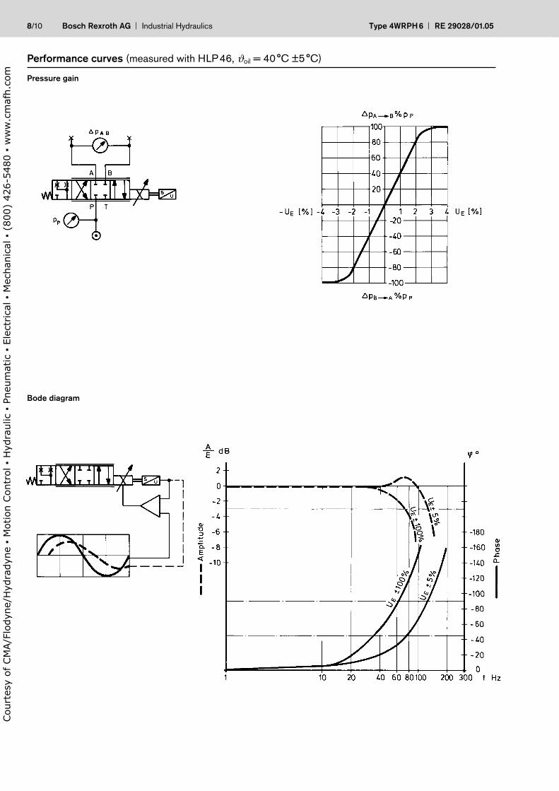
8/10 Bosch Rexroth AG Industrial Hydraulics Type 4WRPH6 RE 29028/01.05
Performance curves (measured with HLP46, ϑoil = 40°C ±5°C)
Pressure gain
Bode diagram
Court
esy
of CM
A/F
lodyn
e/H
ydra
dyn
e
Motion C
ontr
ol
Hyd
raulic
P
neu
mat
ic
Ele
ctrica
l
Mec
han
ical
(
800)
426-5
480
ww
w.c
maf
h.c
om
RE 29028/01.05 Type 4WRPH6 Industrial Hydraulics Bosch Rexroth AG 9/10
Unit dimensions (nominal dimensions in mm)
Mounting hole configuration: NG6 (ISO 4401-03-02-0-94)
For subplates, see catalogue section
RE 45053
1) Deviates from standard2) Thread depth:
Ferrous metal 1.5xØ
Non-ferrous 2 xØ
Required surface quality of mating
component
P A T B F1 F2 F3 F4
21.5 12.5 21.5 30.2 0 40.5 40.5 0
25.9 15.5 5.1 15.5 0 –0.75 31.75 31
8 1) 8 1) 8 1) 8 1) M5 2) M5 2) M5 2) M5 2)
X
Y
Court
esy
of CM
A/F
lodyn
e/H
ydra
dyn
e
Motion C
ontr
ol
Hyd
raulic
P
neu
mat
ic
Ele
ctrica
l
Mec
han
ical
(
800)
426-5
480
ww
w.c
maf
h.c
om
10/10 Bosch Rexroth AG Industrial Hydraulics Type 4WRPH6 RE 29028/01.05
Notes
Bosch Rexroth AG
Industrial Hydraulics
Zum Eisengießer 1
D-97816 Lohr am Main, Germany
Telefon +49(0)9352/18-0
Telefax +49(0)9352/18-2358
www.boschrexroth.de
© Bosch Rexroth AG reserves all rights, including industrial property rights.
We reserve all rights of disposal, such as copying and passing on to third
parties.
The data specified above only serve to describe the product. No statements
concerning a certain condition or suitability for a certain application can be
derived from our information. The given information does not release the user
from the obligation of own judgement and verification. It must be remembered
that our products are subject to a natural process of wear and aging.
Court
esy
of CM
A/F
lodyn
e/H
ydra
dyn
e
Motion C
ontr
ol
Hyd
raulic
P
neu
mat
ic
Ele
ctrica
l
Mec
han
ical
(
800)
426-5
480
ww
w.c
maf
h.c
om
Notes
RE 29028/01.05 Type 4WRPH6 Industrial Hydraulics Bosch Rexroth AG
Bosch Rexroth AG
Industrial Hydraulics
Zum Eisengießer 1
D-97816 Lohr am Main, Germany
Telefon +49(0)9352/18-0
Telefax +49(0)9352/18-2358
www.boschrexroth.de
© Bosch Rexroth AG reserves all rights, including industrial property rights.
We reserve all rights of disposal, such as copying and passing on to third
parties.
The data specified above only serve to describe the product. No statements
concerning a certain condition or suitability for a certain application can be
derived from our information. The given information does not release the user
from the obligation of own judgement and verification. It must be remembered
that our products are subject to a natural process of wear and aging.
Court
esy
of CM
A/F
lodyn
e/H
ydra
dyn
e
Motion C
ontr
ol
Hyd
raulic
P
neu
mat
ic
Ele
ctrica
l
Mec
han
ical
(
800)
426-5
480
ww
w.c
maf
h.c
om
Bosch Rexroth AG Industrial Hydraulics Type 4WRPH6 RE 29028/01.05
Notes
Bosch Rexroth AG
Industrial Hydraulics
Zum Eisengießer 1
D-97816 Lohr am Main, Germany
Telefon +49(0)9352/18-0
Telefax +49(0)9352/18-2358
www.boschrexroth.de
© Bosch Rexroth AG reserves all rights, including industrial property rights.
We reserve all rights of disposal, such as copying and passing on to third
parties.
The data specified above only serve to describe the product. No statements
concerning a certain condition or suitability for a certain application can be
derived from our information. The given information does not release the user
from the obligation of own judgement and verification. It must be remembered
that our products are subject to a natural process of wear and aging.
Court
esy
of CM
A/F
lodyn
e/H
ydra
dyn
e
Motion C
ontr
ol
Hyd
raulic
P
neu
mat
ic
Ele
ctrica
l
Mec
han
ical
(
800)
426-5
480
ww
w.c
maf
h.c
om