Embed Size (px)
Citation preview
International Journal of Science and Research (IJSR) ISSN (Online): 2319-7064
Impact Factor (2012): 3.358
Volume 3 Issue 9, September 2014 www.ijsr.net
Licensed Under Creative Commons Attribution CC BY
Hybrid PV/Fuel Cell System Design and Simulation
Vipin Kumar Maharia1, Girish Dalal2
1Mewar University, Department of Electrical Engineering, Chittorgarh, Rajasthan, India
2Mewar University, Department of Electrical and Electronics Engineering, Chittorgarh, Rajasthan, India
Abstract: In this paper, a hybrid Photovoltaic (PV)-fuel cell generation system employing an electrolyzer for hydrogen generation is designed and simulated. The system is applicable for remote areas or isolated loads. Fuzzy regression model (FRM) is applied for maximum power point tracking to extract maximum available solar power from PV arrays under variable insolation conditions. The system incorporates a controller designed to achieve permanent power supply to the load via the PV array or the fuel cell, or both according to the power available from the sun. Keywords: Photovoltaic (PV)-Fuel Cell, MOSFET, MATLAB 1. Introduction Renewable energy sources (solar, wind, etc.) are attracting more attention as alternative energy sources to conventional fossil fuel energy sources. This is not only due to the diminishing fuel sources, but also due to environmental pollution and global warming problems. Among these sources is the solar energy, which is the most promising, as the fabrication of less costly PV devices becomes a reality. With increased penetration of solar PV devices, various antipollution apparatus can be operated such as water purification through electrochemical processing and stopping desert expansion by PV water pumping with tree plantation. However, control problems arise due to large variances of PV output power under different insolation levels. To overcome this problem, PV power plants are integrated with other power sources or storage system such as hydrogen generator, storage and fuel cells. The fuel cell (FC) is an electrochemical device that produces direct current electricity through the reaction of hydrogen and oxygen in the presence of an electrolyte. They are an attractive option for use with intermittent sources of generation, like the PV, because of high efficiency, fast load response, modularity, and fuel flexibility unlike a battery, a FC does not require recharging. Their feasibility in coordination with PV systems has been successfully demonstrated for both grid-connected and stand-alone applications [1]. Other advantages of FC are the reusability of exhaust heat, on-site installation, and diversity of fuels. The fuel for the FC can be hydrogen or any other hydrogen-containing compound, which on reprocessing can produce hydrogen. The use of electrolysis to produce hydrogen from water is an efficient method from very small to very large scales. Additionally, when PV is used with the electrolyzes, it is the cleanest source of hydrogen with no pollutants produced. On the small scale, a PV array coupled to an electrolyzes and H2 storage tank provides a flexible system, which could be installed in any location with little maintenance.
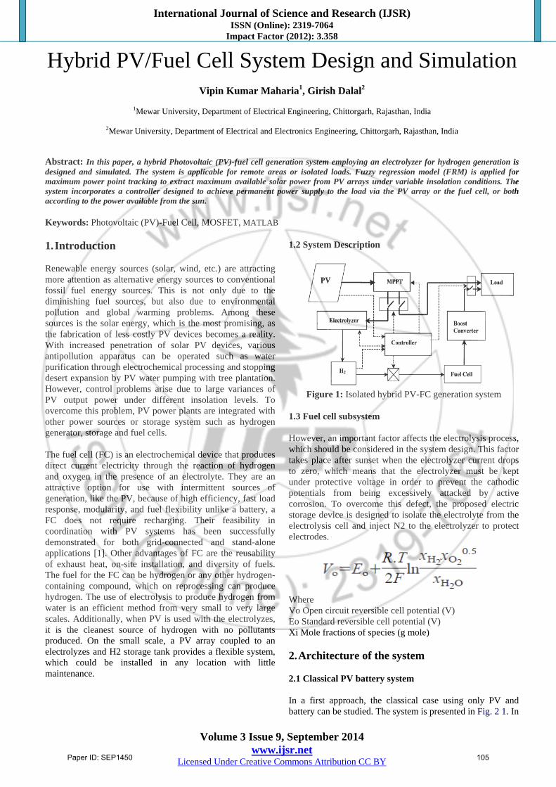
1.2 System Description
Figure 1: Isolated hybrid PV-FC generation system
1.3 Fuel cell subsystem However, an important factor affects the electrolysis process, which should be considered in the system design. This factor takes place after sunset when the electrolyzer current drops to zero, which means that the electrolyzer must be kept under protective voltage in order to prevent the cathodic potentials from being excessively attacked by active corrosion. To overcome this defect, the proposed electric storage device is designed to isolate the electrolyte from the electrolysis cell and inject N2 to the electrolyzer to protect electrodes.
Where Vo Open circuit reversible cell potential (V) Eo Standard reversible cell potential (V) Xi Mole fractions of species (g mole) 2. Architecture of the system 2.1 Classical PV battery system In a first approach, the classical case using only PV and battery can be studied. The system is presented in Fig. 2 1. In
Paper ID: SEP1450 105
International Journal of Science and Research (IJSR) ISSN (Online): 2319-7064
Impact Factor (2012): 3.358
Volume 3 Issue 9, September 2014 www.ijsr.net
Licensed Under Creative Commons Attribution CC BY
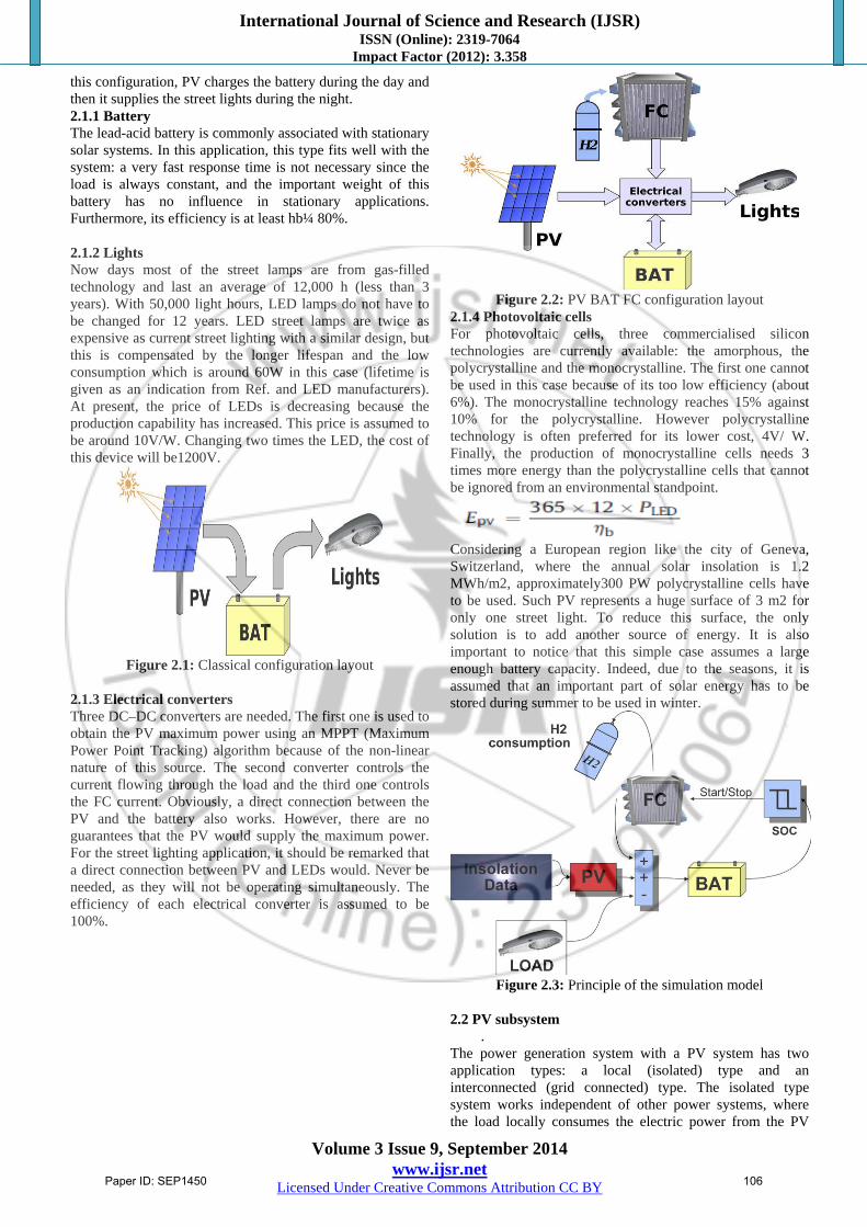
this configuration, PV charges the battery during the day and then it supplies the street lights during the night. 2.1.1 Battery The lead-acid battery is commonly associated with stationary solar systems. In this application, this type fits well with the system: a very fast response time is not necessary since the load is always constant, and the important weight of this battery has no influence in stationary applications. Furthermore, its efficiency is at least hb¼ 80%. 2.1.2 Lights Now days most of the street lamps are from gas-filled technology and last an average of 12,000 h (less than 3 years). With 50,000 light hours, LED lamps do not have to be changed for 12 years. LED street lamps are twice as expensive as current street lighting with a similar design, but this is compensated by the longer lifespan and the low consumption which is around 60W in this case (lifetime is given as an indication from Ref. and LED manufacturers). At present, the price of LEDs is decreasing because the production capability has increased. This price is assumed to be around 10V/W. Changing two times the LED, the cost of this device will be1200V.
Figure 2.1: Classical configuration layout
2.1.3 Electrical converters Three DC–DC converters are needed. The first one is used to obtain the PV maximum power using an MPPT (Maximum Power Point Tracking) algorithm because of the non-linear nature of this source. The second converter controls the current flowing through the load and the third one controls the FC current. Obviously, a direct connection between the PV and the battery also works. However, there are no guarantees that the PV would supply the maximum power. For the street lighting application, it should be remarked that a direct connection between PV and LEDs would. Never be needed, as they will not be operating simultaneously. The efficiency of each electrical converter is assumed to be 100%.
Figure 2.2: PV BAT FC configuration layout
2.1.4 Photovoltaic cells For photovoltaic cells, three commercialised silicon technologies are currently available: the amorphous, the polycrystalline and the monocrystalline. The first one cannot be used in this case because of its too low efficiency (about 6%). The monocrystalline technology reaches 15% against 10% for the polycrystalline. However polycrystalline technology is often preferred for its lower cost, 4V/ W. Finally, the production of monocrystalline cells needs 3 times more energy than the polycrystalline cells that cannot be ignored from an environmental standpoint.
Considering a European region like the city of Geneva, Switzerland, where the annual solar insolation is 1.2 MWh/m2, approximately300 PW polycrystalline cells have to be used. Such PV represents a huge surface of 3 m2 for only one street light. To reduce this surface, the only solution is to add another source of energy. It is also important to notice that this simple case assumes a large enough battery capacity. Indeed, due to the seasons, it is assumed that an important part of solar energy has to be stored during summer to be used in winter.
Figure 2.3: Principle of the simulation model
2.2 PV subsystem
. The power generation system with a PV system has two application types: a local (isolated) type and an interconnected (grid connected) type. The isolated type system works independent of other power systems, where the load locally consumes the electric power from the PV
Paper ID: SEP1450 106
International Journal of Science and Research (IJSR) ISSN (Online): 2319-7064
Impact Factor (2012): 3.358
Volume 3 Issue 9, September 2014 www.ijsr.net
Licensed Under Creative Commons Attribution CC BY
system. The output power of the PV system, however, fluctuates depending on solar insolation and surface temperature. Then a storage system must be used to deliver the required power at lower insolation levels and during the night. Fig.2.3 shows the measured insolation levels during one year (1996). The panel surface temperature varies between 14 and 60°C during the year. The MPP voltage and current Vm, I’m respectively are determined on-line using. The fuzzy model input parameters are: 1. The solar insolation incident on the panel surface (W). 2. The panel surface temperature (T). The determined MPP current is fed to the electrolyzer model to calculate the amount of H2 generated. The H2 is fed with the amount of air required for FC operation. 2.3 Photovoltaic Effect Photovoltaic (PV) is a method of generating electrical power by converting solar radiation into direct current electricity using semiconductors that exhibit the photovoltaic effect. Photovoltaic power generation employs solar panels comprising a number of cells containing a photovoltaic material. Materials presently used for photovoltaic include mono crystalline silicon, polycrystalline silicon, amorphous silicon, cadmium telluride, and copper indium selenide/sulfide. Due to the growing demand for renewable energy sources, the manufacturing of solar cells and photovoltaic arrays has advanced considerably in recent years. The photovoltaic effect is the generation of a voltage (or a corresponding electric current) in a material upon exposure to light. Though the photovoltaic effect is directly related to the photoelectric effect, the two processes are different and should be distinguished. In the photoelectric effect, electrons are ejected from a material's surface upon exposure to radiation of sufficient energy. The photovoltaic effect is different in that the generated electrons are transferred between different bands (i.e. from the valence to conduction bands) within the material, resulting in the buildup of a
voltage between two electrodes.
Figure 2.4 PV effect converts the photon energy into voltage
across the pn junction 2.4 Applications In Buildings In Transport Standalone Devices Rural Electrification Solar roadways Solar Power Satellites
Figure 2.5: PV cell equivalent circuit
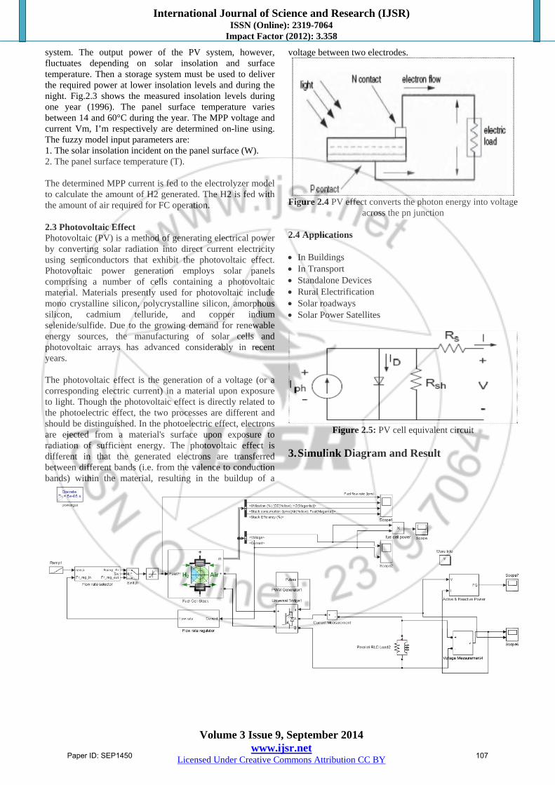
3. Simulink Diagram and Result
Paper ID: SEP1450 107
International Journal of Science and Research (IJSR) ISSN (Online): 2319-7064
Impact Factor (2012): 3.358
Volume 3 Issue 9, September 2014 www.ijsr.net
Licensed Under Creative Commons Attribution CC BY
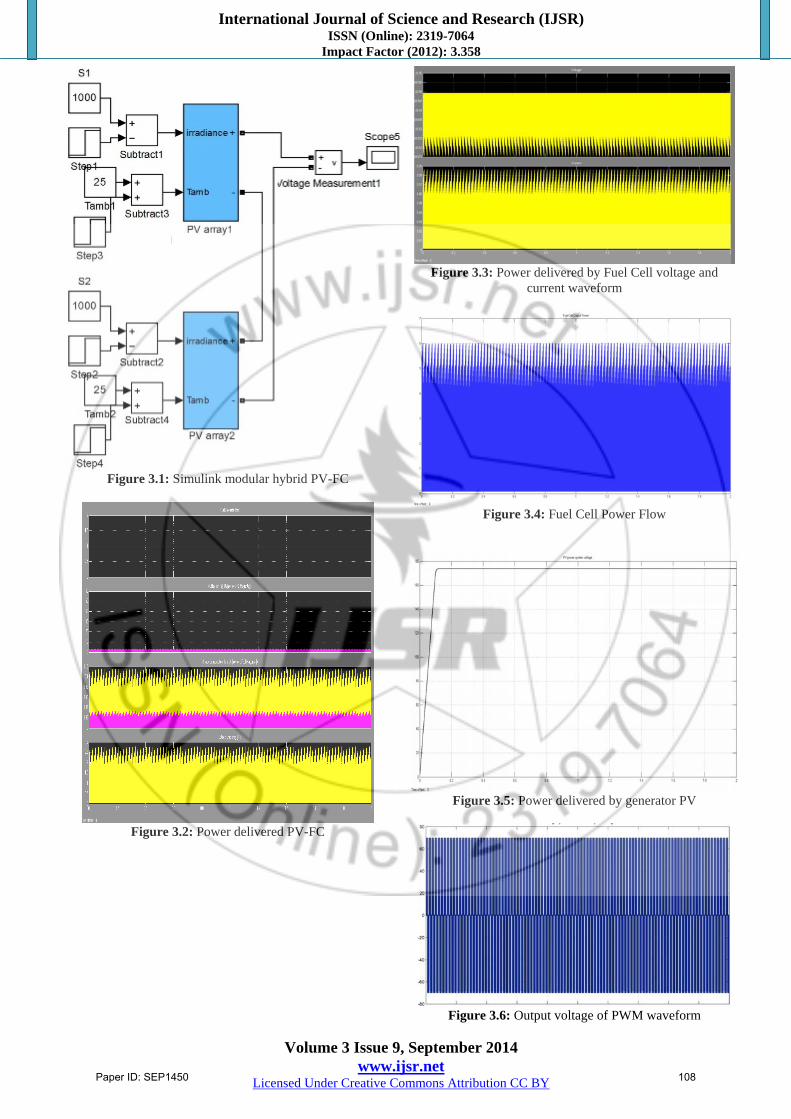
Figure 3.1: Simulink modular hybrid PV-FC
Figure 3.2: Power delivered PV-FC
Figure 3.3: Power delivered by Fuel Cell voltage and
current waveform
Figure 3.4: Fuel Cell Power Flow
Figure 3.5: Power delivered by generator PV
Figure 3.6: Output voltage of PWM waveform
Paper ID: SEP1450 108
International Journal of Science and Research (IJSR) ISSN (Online): 2319-7064
Impact Factor (2012): 3.358
Volume 3 Issue 9, September 2014 www.ijsr.net
Licensed Under Creative Commons Attribution CC BY
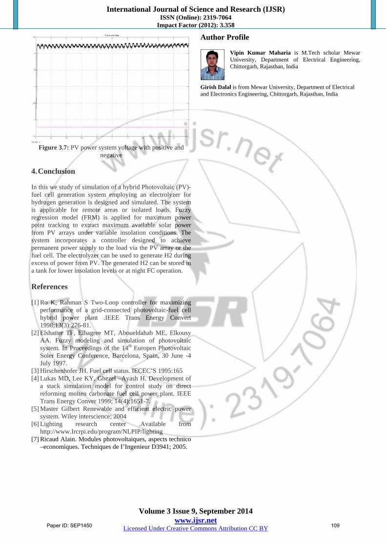
Figure 3.7: PV power system voltage with positive and
negative 4. Conclusion In this we study of simulation of a hybrid Photovoltaic (PV)-fuel cell generation system employing an electrolyzer for hydrogen generation is designed and simulated. The system is applicable for remote areas or isolated loads. Fuzzy regression model (FRM) is applied for maximum power point tracking to extract maximum available solar power from PV arrays under variable insolation conditions. The system incorporates a controller designed to achieve permanent power supply to the load via the PV array or the fuel cell. The electrolyzer can be used to generate H2 during excess of power from PV. The generated H2 can be stored in a tank for lower insolation levels or at night FC operation. References
[1] Ro K, Rahman S Two-Loop controller for maximizing
performance of a grid-connected photovoltaic-fuel cell hybrid power plant .IEEE Trans Energy Convert 1998;13(3):276-81.
[2] Elshatter TF, Elhagree MT, Aboueldahab ME, Elkousy AA. Fuzzy modeling and simulation of photovoltaic system. In Proceedings of the 14th Europen Photovoltaic Soler Energy Conference, Barcelona, Spain, 30 June -4 July 1997.
[3] Hirschenhofer JH. Fuel cell status. IECEC’S 1995:165 [4] Lukas MD, Lee KY, Ghezel –Ayash H. Development of
a stack simulation model for control study on direct reforming molten carbonate fuel cell power plant. IEEE Trans Energy Conver 1999; 14(4):1651-7.
[5] Master Gilbert Renewable and efficient electric power system. Wiley interscience; 2004
[6] Lighting research center .Available from http://www.Ircrpi.edu/program/NLPIP/lighting
[7] Ricaud Alain. Modules photovoltaiques, aspects technico –economiques. Techniques de I’Ingenieur D3941; 2005.
Author Profile
Vipin Kumar Maharia is M.Tech scholar Mewar University, Department of Electrical Engineering, Chittorgarh, Rajasthan, India
Girish Dalal is from Mewar University, Department of Electrical and Electronics Engineering, Chittorgarh, Rajasthan, India
Paper ID: SEP1450 109