Embed Size (px)
Citation preview
June 2003 • NREL/SR-560-32743
T.S. Key, H.E. Sitzlar, and T.D. Geist EPRI PEAC Corp. Knoxville, Tennessee
Fast Response, Load-Matching Hybrid Fuel Cell Final Technical Progress Report
National Renewable Energy Laboratory 1617 Cole Boulevard Golden, Colorado 80401-3393 NREL is a U.S. Department of Energy Laboratory Operated by Midwest Research Institute • Battelle • Bechtel
Contract No. DE-AC36-99-GO10337
June 2003 • NREL/SR-560-32743
Fast Response, Load-Matching Hybrid Fuel Cell Final Technical Progress Report
T.S. Key, H.E. Sitzlar, and T.D. Geist EPRI PEAC Corp. Knoxville, Tennessee
NREL Technical Monitor: Thomas Basso Prepared under Subcontract No. NAD-1-30605-15
National Renewable Energy Laboratory 1617 Cole Boulevard Golden, Colorado 80401-3393 NREL is a U.S. Department of Energy Laboratory Operated by Midwest Research Institute • Battelle • Bechtel
Contract No. DE-AC36-99-GO10337

NOTICE This report was prepared as an account of work sponsored by an agency of the United States government. Neither the United States government nor any agency thereof, nor any of their employees, makes any warranty, express or implied, or assumes any legal liability or responsibility for the accuracy, completeness, or usefulness of any information, apparatus, product, or process disclosed, or represents that its use would not infringe privately owned rights. Reference herein to any specific commercial product, process, or service by trade name, trademark, manufacturer, or otherwise does not necessarily constitute or imply its endorsement, recommendation, or favoring by the United States government or any agency thereof. The views and opinions of authors expressed herein do not necessarily state or reflect those of the United States government or any agency thereof.
Available electronically at http://www.osti.gov/bridge
Available for a processing fee to U.S. Department of Energy and its contractors, in paper, from:
U.S. Department of Energy Office of Scientific and Technical Information P.O. Box 62 Oak Ridge, TN 37831-0062 phone: 865.576.8401 fax: 865.576.5728 email: [email protected]
Available for sale to the public, in paper, from:
U.S. Department of Commerce National Technical Information Service 5285 Port Royal Road Springfield, VA 22161 phone: 800.553.6847 fax: 703.605.6900 email: [email protected] online ordering: http://www.ntis.gov/ordering.htm
Printed on paper containing at least 50% wastepaper, including 20% postconsumer waste
iii
Abstract
Hybrid distributed energy resource technologies are systems that combine two complementary generation or storage technologies. Interconnected with the grid, these systems can provide improved performance over a single power source and add value when matched to appropriate applications.
In a typical residence, for electric power technologies interconnected with the grid, a key measure of hybrid system performance is the response of the system to nonlinear loads and step loads, e.g., motors. Of further interest is the ability of the hybrid system to improve the quality of electric service provided by the utility. The interconnected hybrid system could provide power during a utility outage and also compensate for voltage sags in utility service. Such a hybrid system would then function as a premium power provider and eliminate the potential need for an uninterruptible power supply.
In this research project, a proton exchange membrane (PEM) fuel cell is combined with a relatively new product—an asymmetrical ultracapacitor—to provide a more robust power response to changes in system loading. Together, the fuel cell and the ultracapacitor serve both full-time and momentary loading. The very fast power response of the ultracapacitor complements the slower but longer-term power output of the fuel cell. The hybrid combination provides for power system response characteristics that are desired to serve a range of load and grid-interface requirements. This project also demonstrates the potential of hybrid DER technologies to improve overall power system capacity and compatibility with a variety of loads.
This report covers the activities and accomplishments during the base year of a proposed 3-year-option project. Included are:
• A review of grid-interconnection technical requirements • Baseline testing of the PEM fuel cell and asymmetrical ultracapacitors as separate
components • Specifications for the hybrid fuel cell system with integrated energy storage.
The hybrid system was assembled, and some tests were conducted in the first year in preparation for future detailed system testing of the prototype unit. These preliminary test results and the hybrid system design and integration issues are reported. System integration issues include all system components and controls necessary to achieve the interconnection with local end-use loads and the electric grid. An appendix of this report also provides an overview of the ultracapacitor technology selected for the hybrid system. The optional project tasks beyond the base year were not pursued.

iv
v
Table of Contents
List of Figures.............................................................................................................................. vii List of Tables ................................................................................................................................ ix 1. Introduction............................................................................................................................. 1
1.1 Hybrid Distributed Energy Resource System with Improved Dynamic Performance ....... 1 1.2 Scope of Work .................................................................................................................... 3
1.2.1 Base Year Task 1: Evaluate Individual Components and System Cost and Performance ............................................................................................................ 3
1.2.2 Base Year Task 2: Design a Fuel Cell and Electrochemical Capacitor Hybrid System..................................................................................................................... 5
1.2.3 Option Year 1 Task 3: Build and Evaluate a Prototype Hybrid System....................... 6 1.2.4 Option Year 2 Task 4: Analyze the Preliminary Performance of the Prototype
Hybrid System ........................................................................................................ 6 2. Component and System Test Results .................................................................................... 8
2.1 Fuel Cell Component Test Results ..................................................................................... 8 2.1.1 Monitoring Software................................................................................................... 14 2.1.2 Standby Testing of Fuel Cell ...................................................................................... 15 2.1.3 Power and Harmonics ................................................................................................. 16 2.1.4 Fuel Cell System Output Characteristics .................................................................... 18 2.1.5 Performance and Modeling Results ............................................................................ 19 2.1.6 Fuel Cell Step-Load Response.................................................................................... 20 2.1.7 Energy Efficiency ....................................................................................................... 21
2.2 Ultracapacitor Component Test Results ........................................................................... 22 2.2.1 Visual Inspection ........................................................................................................ 22 2.2.2 Capacity with Load ..................................................................................................... 23 2.2.3 Capacity with Temperature......................................................................................... 28 2.2.4 Equivalent Series Resistance ...................................................................................... 30
2.3 Preliminary System Test Results ...................................................................................... 31 2.3.1 Hybrid System Components and Operating Modes.................................................... 31 2.3.2 System Step Response – Fuel Cell with Power Electronics ....................................... 32 2.3.3 System Step Response – Fuel Cell Loaded................................................................. 33 2.3.4 System Step Response – Cross Over .......................................................................... 33 2.3.5 System Step Response – Motor Load ......................................................................... 34 2.3.6 System Recharge of Energy Storage........................................................................... 35
3. Hybrid System Design .......................................................................................................... 37
3.1 Hybrid System Design Objective...................................................................................... 37 3.2 Prime Mover Specification (Fuel Cell with Power Electronics) ...................................... 37
3.2.1 Fuel Cell Technology Selection.................................................................................. 37 3.2.2 Specification of Fuel Cell and Power Electronics ...................................................... 38
3.3 Energy Storage Component Specification ........................................................................ 42 3.3.1 Energy Storage Technology Selection........................................................................ 42 3.3.2 Specification of the Ultracapacitor ............................................................................. 45
vi
3.4 System Design Summary.................................................................................................. 48 3.4.1 Hybrid System Challenges.......................................................................................... 49 3.4.2 Hybrid System Performance Advantages ................................................................... 50 3.4.3 Hybrid System Disadvantages .................................................................................... 52
4. DER Grid-Interconnection Practices .................................................................................. 53
4.1 Introduction....................................................................................................................... 53 4.2 Grid-Connection of Distributed Energy Resources .......................................................... 53 4.3 Power Conversion Elements ............................................................................................. 53
4.3.1 Rotating Power Converters ......................................................................................... 56 4.3.2 Inverters ...................................................................................................................... 57
4.4 Relay Protection................................................................................................................ 60 4.4.1 Passive Protection ....................................................................................................... 60 4.4.2 Active Protection ........................................................................................................ 61
4.5 Interconnection Transformer ............................................................................................ 61 4.5.1 Transformer Connections............................................................................................ 62 4.5.2 Common Transformer Configurations........................................................................ 63 4.5.3 Interconnection Support Equipment ........................................................................... 65
5. References .............................................................................................................................. 67 6. Related Reading .................................................................................................................... 68 Appendix: Double-Layer Electrochemical Capacitors........................................................ A-1
A.1 Background ..................................................................................................................... A-1 A.2 Availability ..................................................................................................................... A-2 A.3 Comparison with Other Similar Storage Technologies .................................................. A-3 A.4 Capacitor Reliability ....................................................................................................... A-4 A.5 Voltage Balance .............................................................................................................. A-4 A.6 Status of Large (>1 kJ) Capacitor Development ............................................................ A-5 A.7 Ultracapacitor Supplemental Test Results ...................................................................... A-6 A.8 Ultracapacitors as UPS Battery Replacement................................................................. A-6 A.9 Integration into Adjustable-Speed Drives....................................................................... A-8
vii
List of Figures Figure 1-1. Effect of energy storage on the voltage and frequency output of an off-grid
distributed generator during a large load step.................................................................. 3 Figure 2-1. The testing area and test equipment ................................................................................... 8 Figure 2-2. The front of the fuel cell cabinet ........................................................................................ 8 Figure 2-3. Right view of the fuel cell cabinet and hydrogen tanks ..................................................... 9 Figure 2-4. The back of the fuel cell cabinet ........................................................................................ 9 Figure 2-5. The hydrogen sensor mounted near the ceiling above the hydrogen tanks...................... 10 Figure 2-6. Right side of the electronics cabinet ................................................................................ 10 Figure 2-7. Overall dimensions of the fuel cell system ...................................................................... 11 Figure 2-8. Simplified schematic showing the various subsystems within the fuel cell system ........ 12 Figure 2-9. Operational schematic of PEM fuel cell .......................................................................... 12 Figure 2-10. Left view of the fuel cell cabinet showing the three fuel cell stacks ............................. 13 Figure 2-11. A screen capture showing the monitoring of the fuel cell’s three stacks....................... 14 Figure 2-12. A screen capture showing gas and water controls and various pressures within the
fuel cell........................................................................................................................... 14 Figure 2-13. A screen capture showing the status of various components within the fuel cell as
well as the electrical status............................................................................................. 15 Figure 2-14. Standby test showing stack failure................................................................................. 15 Figure 2-15. A screen capture from a Fluke 41 showing the electrical characteristics for Phase
A of the fuel cell when operating in island mode .......................................................... 16 Figure 2-16. A screen capture from a Fluke 41 showing the electrical characteristics for Phase
B of the fuel cell when operating in island mode .......................................................... 17 Figure 2-17. A screen capture from a Fluke 41 showing the electrical characteristics for Phase
C of the fuel cell when operating in island mode .......................................................... 17 Figure 2-18. Fuel cell stack voltage versus current ............................................................................ 18 Figure 2-19. Basic fuel cell stack performance .................................................................................. 20 Figure 2-20. Step response of the fuel cell from light load to full load.............................................. 21 Figure 2-21. Step response of the fuel cell from full load to light load.............................................. 21 Figure 2-22. Simplified configuration for measurement of capacity with load.................................. 24 Figure 2-23. ESMA EC501 runtime versus load ................................................................................ 26 Figure 2-24. ESMA EC501 percent of rated energy versus load ....................................................... 26 Figure 2-25. ELIT 24PP runtime versus load ..................................................................................... 27 Figure 2-26. ELIT 24PP percent of rated capacitance versus load..................................................... 27 Figure 2-27. ESMA EC203, percent of nominal energy as temperature is varied ............................. 29 Figure 2-28. ELIT 24PP percent of nominal capacitance as temperature is varied............................ 30 Figure 2-29. Simplified schematic showing various subsystems in the fuel cell system ................... 31 Figure 2-30. Step load from near zero load to full load (3 kW) with ultracapacitor and fuel cell
output equal.................................................................................................................... 32 Figure 2-31. Step loading to full load when ultracapacitor is charging.............................................. 33 Figure 2-32. Step load to full load (3 kW) and maintain load for 100 seconds.................................. 34 Figure 2-33. Startup of a 1½ hp motor, three-phase, 208 V ............................................................... 34 Figure 2-34. Inrush to a ¼ hp, 120-V fan motor................................................................................. 35 Figure 2-35. Plot of the fuel cell recharging the ultracapacitor after the load has been turned
off................................................................................................................................... 36
viii
Figure 3-1. Comparison of storage options......................................................................................... 44 Figure 3-2. Specific power versus discharge time .............................................................................. 45 Figure 3-3. Energy and capacitance for a given runtime at a fixed load ............................................ 46 Figure 3-4. Simplified schematic showing energy storage added to the system ................................ 49 Figure 4-1. Technology comparison of generation and energy storage technologies ........................ 54 Figure 4-2. Converter interface between DER and the electric power system................................... 55 Figure 4-3. Recommended interconnection for small three-phase inverter (≤100) with grounded
wye-delta transformer protected by fuses ...................................................................... 58 Figure 4-4. Different DER and utility interface transformer configurations ...................................... 62 Figure 4-5. Typical advantages and disadvantages of various interconnection transformer
configurations ................................................................................................................ 63 Figure A-1. Construction of an electrochemical capacitor with a double-layer .............................. A-2 Figure A-2. Direct replacement life-cycle test setup for the ESMA 501 capacitors ....................... A-6 Figure A-3. Pre-regulator life-cycle test setup for the ELIT 110/220PP capacitor ......................... A-7 Figure A-4. Plot of UPS characteristics with ELIT 110/220PP capacitor....................................... A-7 Figure A-5. Plot of UPS characteristics with ESMA EC501 capacitor........................................... A-8 Figure A-6. ASD ride-through evaluation with ELIT 400-V electrochemical capacitor –
demonstration setup ................................................................................................... A-10 Figure A-7. ASD input voltage...................................................................................................... A-11 Figure A-8. ASD input current ...................................................................................................... A-11 Figure A-9. DC bus voltage and motor current ............................................................................. A-12 Figure A-10. Capacitor characteristics relating power, energy, and discharge time ..................... A-14

ix
List of Tables Table 2-1. Modes and Output Configurations of the Fuel Cell System.............................................. 13 Table 2-2. Specifications for the Tested Electrochemical Capacitors ................................................ 23 Table 2-3. Load Resistance Used for Measurement of Capacity........................................................ 25 Table 2-4. ESR Measurement Results in Ohms.................................................................................. 31 Table 3-1. Modes and Output Configurations for the Fuel Cell System ............................................ 38 Table 3-2. Relative Merits of the Energy-Storage Technologies Considered for Use in the
Hybrid Fuel Cell System................................................................................................ 43 Table 4-1. Types of Energy Sources and Related DER Technologies ............................................... 54 Table A-1. Listing of Manufacturers of Double-Layer Electrochemical Capacitors ...................... A-3 Table A-2. Product Names for Electrochemical Capacitors ............................................................ A-3 Table A-3. Comparison of Traditional Energy Storage Devices ..................................................... A-4 Table A-4. Cost Comparison of Electrochemical Capacitors.......................................................... A-4 Table A-5. Data from Manufacturer Web Site .............................................................................. A-13

x
1
1. Introduction
1.1 Hybrid Distributed Energy Resource System with Improved Dynamic Performance
Many distributed power systems available today—including fuel cells, photovoltaics, wind turbines, and microturbines—do not provide the robust source characteristics required to effectively load-follow during significant load steps. There is a market need to improve the dynamic performance of these systems.
A number of U.S. Department of Energy (DOE) programs have shown that hybrid energy systems outperform single technology applications. This advantage is usually gained by combining two technologies that complement each other. When matched to the appropriate applications, hybrids can provide improved performance capabilities and add value to the overall system. For example, in a typical residence, for hybrid power systems interconnected with the grid, a key measure of performance is the response to nonlinear loads and step loads, e.g., motors. Of further interest is the capability of the hybrid system to improve the quality of electric service provided by the utility. The interconnected hybrid system could provide power during a utility outage and also compensate for voltage sags in utility service. Such a system would then function as a premium power provider and eliminate the potential need for an uninterruptible power supply.
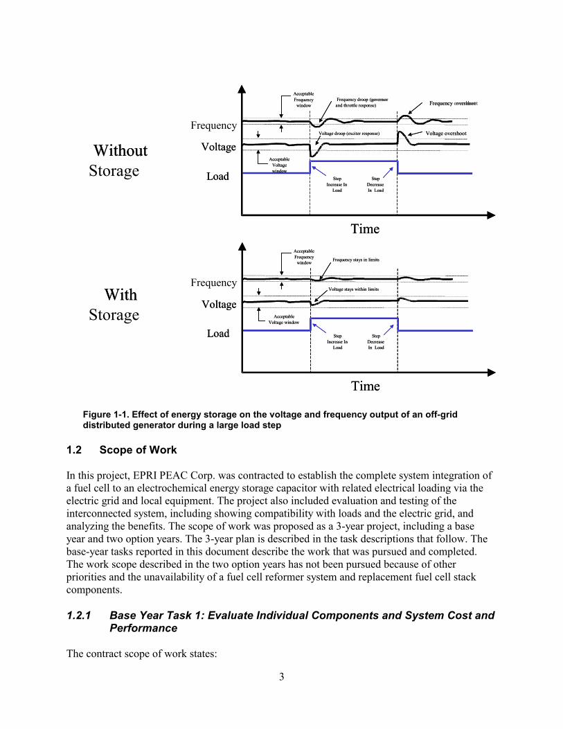
In this project, a proton exchange membrane (PEM) fuel cell will be designed with integrated energy storage to demonstrate the performance enhancements that can be realized by using hybrid technologies. This project will demonstrate how the very fast power response of ultracapacitors can be used to complement the slower but longer-term power output of the fuel cell to produce the compatibility and performance characteristics needed in a load-compatible and versatile power system. A new design of symmetrical ultracapacitors will be used to improve the load following characteristics of a PEM fuel cell by providing a more robust power response to changes in system loading. During motor starts or other significant increases in load, the ultracapacitors will provide the balance of real and reactive power needed during the momentary load transition period (see Figure 1-1). During sudden loss of load, the ultracapacitors will absorb excess energy from the generator source. Adding ultracapacitor energy storage to distributed power systems will improve power quality and efficiency and reduce capital expenses by allowing the systems to be sized more closely to the steady-state power requirements, rather than oversizing the generator to meet transient loading requirements.
This report covers the activities and accomplishments during the base year of the project. Included are a review of grid-interconnection technical requirements, baseline testing of the PEM fuel cell and asymmetrical ultracapacitors as separate components, and specifications for the hybrid fuel cell system with integrated energy storage. The hybrid system was assembled, and some tests were conducted in anticipation of future demonstration and testing of the prototype unit. The base year results and the system design, including all system components and controls necessary to achieve the integration and interconnection with local end-use loads and

2
the electric grid, are reported. This report also provides an overview of the new ultracapacitor technology.
The significance of this project stems from the fact that it addresses the pulse load capability problem of a typical PEM fuel cell. This problem is also common in microturbines, photovoltaic systems, and other low-inertia power sources. The hybrid fuel cell and ultracapacitor combination can serve dynamic loads and also provide power conditioning for grid or load transients. In addition, application economics are enhanced because a smaller fuel cell rating is capable of serving the typical inrush and pulse-loading requirement of a practical power system.
The approach taken was to conduct laboratory testing of the ultracapacitor and fuel cell systems separately to establish baseline operating performances. Evaluating the systems separately allowed researchers to point out shortcomings, document the interactions between the distributed power system and the grid, and provide more specific interconnection technical requirements and motivation for the hybrid system. From this knowledge and results, a grid-friendly hybrid distributed power system with integrated energy storage was designed. This hybrid combination promises to serve as a fast-response, load-matching system capable of providing pulse-load electric capacity (large inrush current) while adding a dimension of power conditioning for grid and load transients.
3
Time
Frequency droop (governor and throttle response)
Voltage droop (exciter response)
Step Increase In
Load Load
Frequency
Voltage
Step Decrease In Load
Voltage overshoot
Acceptable Frequency
window
Acceptable Voltage window
Frequency overshoot
Time
Frequency stays in limits
Step Increase In
Load Load
Frequency
Voltage
Step Decrease In Load
Acceptable Frequency
window
Acceptable Voltage window
Voltage stays within limits
Without Storage
With Storage
Time
Frequency droop (governor and throttle response)
Voltage droop (exciter response)
Step Increase In
Load Load
Voltage
Step Decrease In Load
Voltage overshoot
Acceptable Frequency
window
Acceptable Voltage window
Frequency overshoot
Time
Frequency stays in limits
Step Increase In
Load Load
Voltage
Step Decrease In Load
Acceptable Frequency
window
Acceptable Voltage window
Voltage stays within limits
Without
With
Figure 1-1. Effect of energy storage on the voltage and frequency output of an off-grid distributed generator during a large load step
1.2 Scope of Work
In this project, EPRI PEAC Corp. was contracted to establish the complete system integration of a fuel cell to an electrochemical energy storage capacitor with related electrical loading via the electric grid and local equipment. The project also included evaluation and testing of the interconnected system, including showing compatibility with loads and the electric grid, and analyzing the benefits. The scope of work was proposed as a 3-year project, including a base year and two option years. The 3-year plan is described in the task descriptions that follow. The base-year tasks reported in this document describe the work that was pursued and completed. The work scope described in the two option years has not been pursued because of other priorities and the unavailability of a fuel cell reformer system and replacement fuel cell stack components.
1.2.1 Base Year Task 1: Evaluate Individual Components and System Cost and Performance
The contract scope of work states:
4
The subtask activities shall evaluate, analyze and report on the cost and performance of components of a PEM type fuel cell electrochemical capacitor hybrid system. The final preliminary evaluation of configuring the necessary components into a hybrid fuel cell system shall be analyzed and reported.
1.2.1.1 Subtask 1.1: Evaluate Electrochemical Capacitors
The contract scope of work states:
The claims of electrochemical capacitor manufacturers shall be evaluated and verified based on various capacitor modules from two of the leading manufacturers. Under this subtask, EPRI PEAC shall compare the cost and performance of the capacitors to other energy storage solutions in the immediate, medium, and long term time frame with various assumptions regarding performance developments and market conditions.
The capacitor modules had been installed at EPRI PEAC and tested prior to this subcontract. The modules were selected based on capacity and voltage range, and an attempt was made to evaluate the limits of the technology. Key performance characteristics had been identified. Of those characteristics, three were considered for evaluation: (1) capacity with load and temperature, (2) equivalent series resistance, and (3) life cycle. Special measurement techniques had been developed and used for the electrochemical capacitors because of their extremely large capacitance. That required research of nontraditional techniques and the construction of special test fixtures and apparatuses. Laboratory measurements had been documented and compared with manufacturer specification sheets. The main result of the testing was that electrochemical capacitors do meet manufacturer claims of performance.
1.2.1.2 Subtask 1.2: Evaluate a 3-kW Fuel Cell
The contract scope of work states:
EPRI PEAC Corp. shall verify the manufacturer claims for their 3-kW fuel cell system (DCH Technology, Inc.). Under this subtask, EPRI PEAC shall test the fuel cell performance, including but not limited to the following key performance criteria that have been identified: load regulation, overload response, and step-load response. Additionally, EPRI PEAC shall compare the cost and performance of the fuel cell system to other energy solutions, in the immediate, medium, and long-term time frame with various assumptions regarding performance developments and market conditions.
The DCH fuel cell system had been installed prior to this subcontract. That DCH fuel cell system has a patented design under license to DCH Technology Inc. from Los Alamos National Laboratory.
5
The PEM fuel cell has been the hands-on favorite for vehicular development and is now being looked at for stationary applications as well. The PEM advantages—which include low operating temperature, the ability to sustain operation at high current densities, and a lightweight, compact cell structure—make it a good candidate. Another advantage is the technology is licensed to DCH.
Compared with other PEM fuel cells, the DCH fuel cell system has the following key advantages:
• Low parasitic losses compared with other cells. Parasitic losses comprise the energy needed to operate the system fans, pumps, and electronics as a percent of system output rating.
• Use of dry air as opposed to humidified air. This has the advantage of simplifying the control system and allowing for good power output over a larger operating (voltage) range.
• Conducts the heat out of the fuel cell (using dry air). As a result, cooling cells are not needed. Thus, all cells in the stack produce power.
Work completed prior to this subcontract included the concept design, the specification and procurement of the fuel cell, and the fuel cell installation. Ultimately of specific interest is maximizing the power delivery of the fuel cell. A compromise had been reached between the application and capability of the manufacturer's PEM unit. As a result, a 3-kW, 50-V DC fuel cell had been ordered, and included with that fuel cell was a power electronics module that allows the fuel cell to operate in either standalone or grid-connected mode. Currently, the fuel cell will not handle current in excess of its rating. This limits many practical applications, such as compressors on air conditioners and motors on pumps, in which starting or pulse power is required. EPRI PEAC believes that this limitation can be overcome through a hybrid system of electrochemical supercapacitors integrated into a fuel cell.
1.2.2 Base Year Task 2: Design a Fuel Cell and Electrochemical Capacitor Hybrid System
The contract scope of work states:
EPRI PEAC shall design and specify a hybrid system consisting of the fuel cell, electrochemical capacitors, and all system components and controls necessary to achieve the integration, and interconnection with loads and the grid. The goal is to design and specify a prototype version of the hybrid system that can be evaluated in the laboratory. The prototype design and specifications shall include complete functionalities for operability and testability, and shall provide for planned capabilities for correlating the laboratory testing with field-testing of projected commercial units. The functionalities addressed shall include and not be limited to, electrical, mechanical, thermal, environmental conditions. They shall also

6
include communications, controls, monitoring/metering, parameters for data gathering, analysis, and evaluation of the system and its major components-- including provisions accounting for interconnection to the utility grid and loads, and for non-utility tied operations.
A key measure of hybrid system performance is the response of the system to nonlinear loads and step loads as found in a typical residence. Of further interest is the ability of the system to improve the quality of power delivered by the utility. For example, the system may have the capability to provide power not only during an outage but also during sags in the voltage. Such a system would function as a premium power provider and eliminate the need for an uninterruptible power supply (UPS).
1.2.3 Option Year 1 Task 3: Build and Evaluate a Prototype Hybrid System
The contract scope of work states:
EPRI PEAC shall build and evaluate a hybrid system consisting of the fuel cell, electrochemical capacitors, and all system components and controls necessary to achieve integration and interconnection with loads and the grid based on all tasks of this subcontract. This task goal is to achieve a prototype version of the hybrid system and perform evaluations of it in the laboratory.
The evaluations shall establish the technical and cost information pertinent to various distributed energy stakeholders. That includes, but is not limited to, electrical performance (e.g., power and energy ratings, power quality, reactive power), load profiling, conversion efficiencies, environmental performance, cost performance, and safety. For example, a key measure of performance is the response of the system to nonlinear loads and step loads as found in a typical residence. Of further interest will be the ability of the system to improve the quality of power as delivered by the utility, e.g., the system may have the capability to provide power not only during an outage, but also during sags in the voltage. Such a system would function as a premium power provider and eliminate the need for uninterruptible power supplies (UPSs).
1.2.4 Option Year 2 Task 4: Analyze the Preliminary Performance of the Prototype Hybrid System
The contract scope of work states:
EPRI PEAC shall:
• Develop and conduct preliminary tests to provide appropriate data and experience for analysis

7
• Analyze the results, methodologies, operability/testability, and the appropriateness of both the prototype hybrid system and the tests.
• Analyze (from the standpoint of comparative performance) potential costs and benefit to consumers, the utility, and the environment. For example, a nominal economic goal set by the utility industry is about $800/kW to $1,200/kW plus the value added by the short-term storage capacity.
• Recommend target goals for price and performance and suggest feasibility of such goals.
The analyses shall include recommendations for improving the prototype unit and the tests. Further, the analyses shall state the pros and cons of proceeding to a beta test program for such a hybrid fuel cell system. The recommendations shall also include identification of potential partners, and the agreed upon process if a beta test program were to follow.
8
2. Component and System Test Results
2.1 Fuel Cell Component Test Results
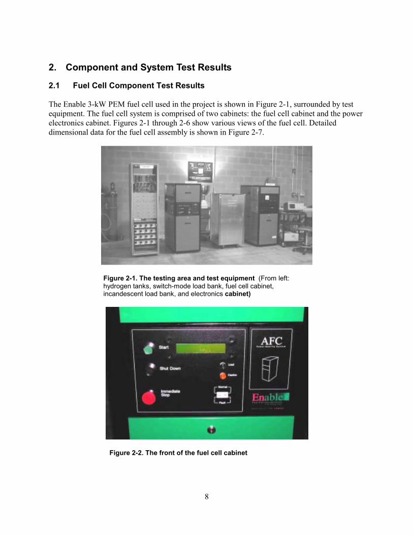
The Enable 3-kW PEM fuel cell used in the project is shown in Figure 2-1, surrounded by test equipment. The fuel cell system is comprised of two cabinets: the fuel cell cabinet and the power electronics cabinet. Figures 2-1 through 2-6 show various views of the fuel cell. Detailed dimensional data for the fuel cell assembly is shown in Figure 2-7.
Figure 2-1. The testing area and test equipment (From left: hydrogen tanks, switch-mode load bank, fuel cell cabinet, incandescent load bank, and electronics cabinet)
Figure 2-2. The front of the fuel cell cabinet
9
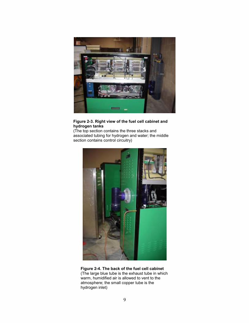
Figure 2-3. Right view of the fuel cell cabinet and hydrogen tanks (The top section contains the three stacks and associated tubing for hydrogen and water; the middle section contains control circuitry)
Figure 2-4. The back of the fuel cell cabinet (The large blue tube is the exhaust tube in which warm, humidified air is allowed to vent to the atmosphere; the small copper tube is the hydrogen inlet)
10
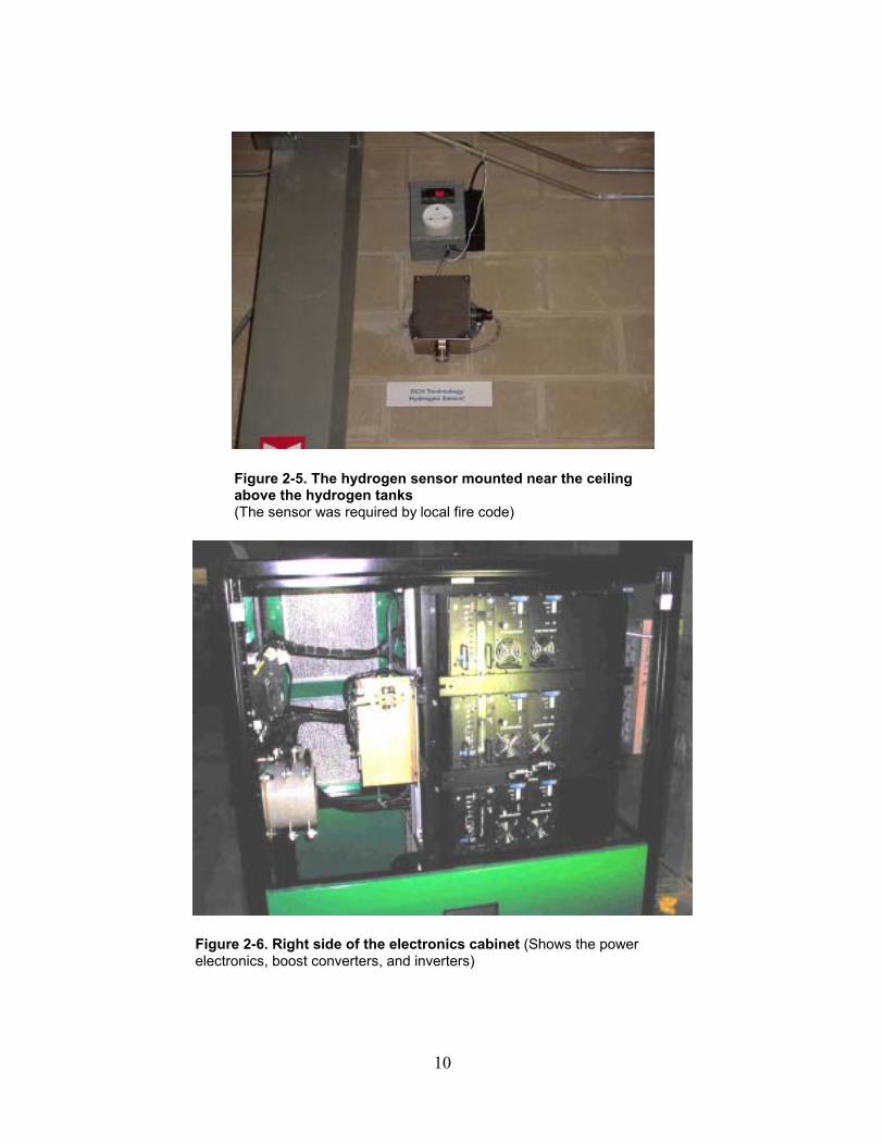
Figure 2-5. The hydrogen sensor mounted near the ceiling above the hydrogen tanks (The sensor was required by local fire code)
Figure 2-6. Right side of the electronics cabinet (Shows the power electronics, boost converters, and inverters)
11
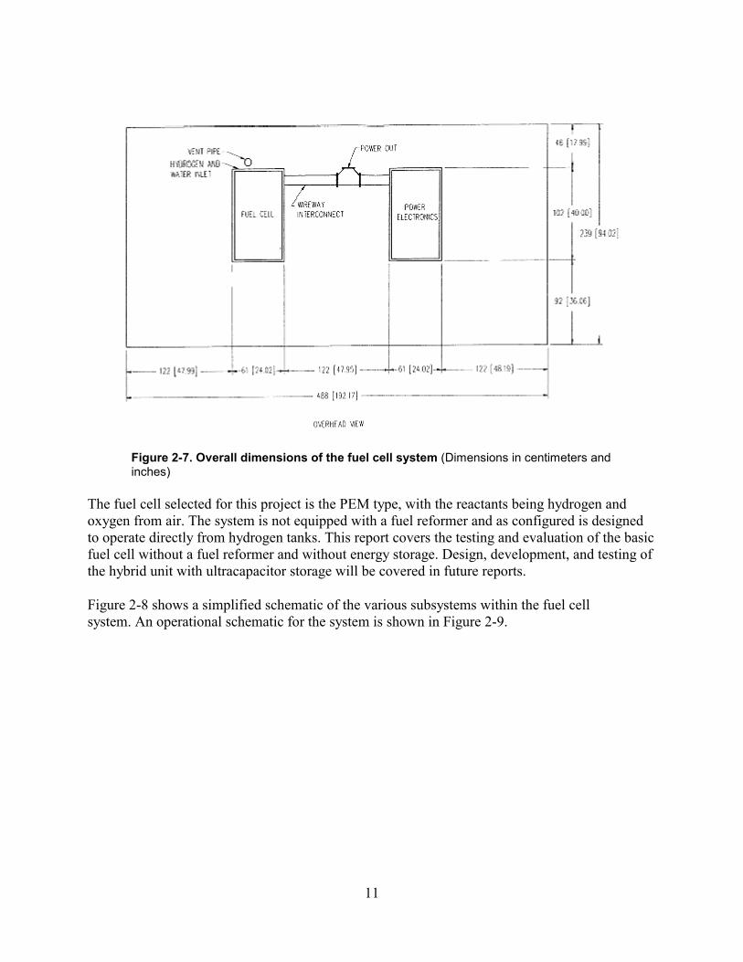
Figure 2-7. Overall dimensions of the fuel cell system (Dimensions in centimeters and inches)
The fuel cell selected for this project is the PEM type, with the reactants being hydrogen and oxygen from air. The system is not equipped with a fuel reformer and as configured is designed to operate directly from hydrogen tanks. This report covers the testing and evaluation of the basic fuel cell without a fuel reformer and without energy storage. Design, development, and testing of the hybrid unit with ultracapacitor storage will be covered in future reports.
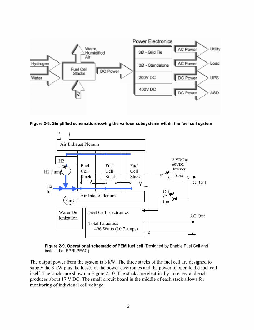
Figure 2-8 shows a simplified schematic of the various subsystems within the fuel cell system. An operational schematic for the system is shown in Figure 2-9.
12
Figure 2-8. Simplified schematic showing the various subsystems within the fuel cell system
Fuel Cell Stack
FuelCellStack
FuelCellStack
Air Intake Plenum
H2 Trap
Fan
Air Exhaust Plenum
Water De ioni zation
H2 Pump
48 VDC to
Inverter
Fuel Cell Electronics Total Parasitics 496 Watts (10.7 amps)
Run
OffH2 In
AC Out
DC Out DC/DC
60VDC
Figure 2-9. Operational schematic of PEM fuel cell (Designed by Enable Fuel Cell and installed at EPRI PEAC)
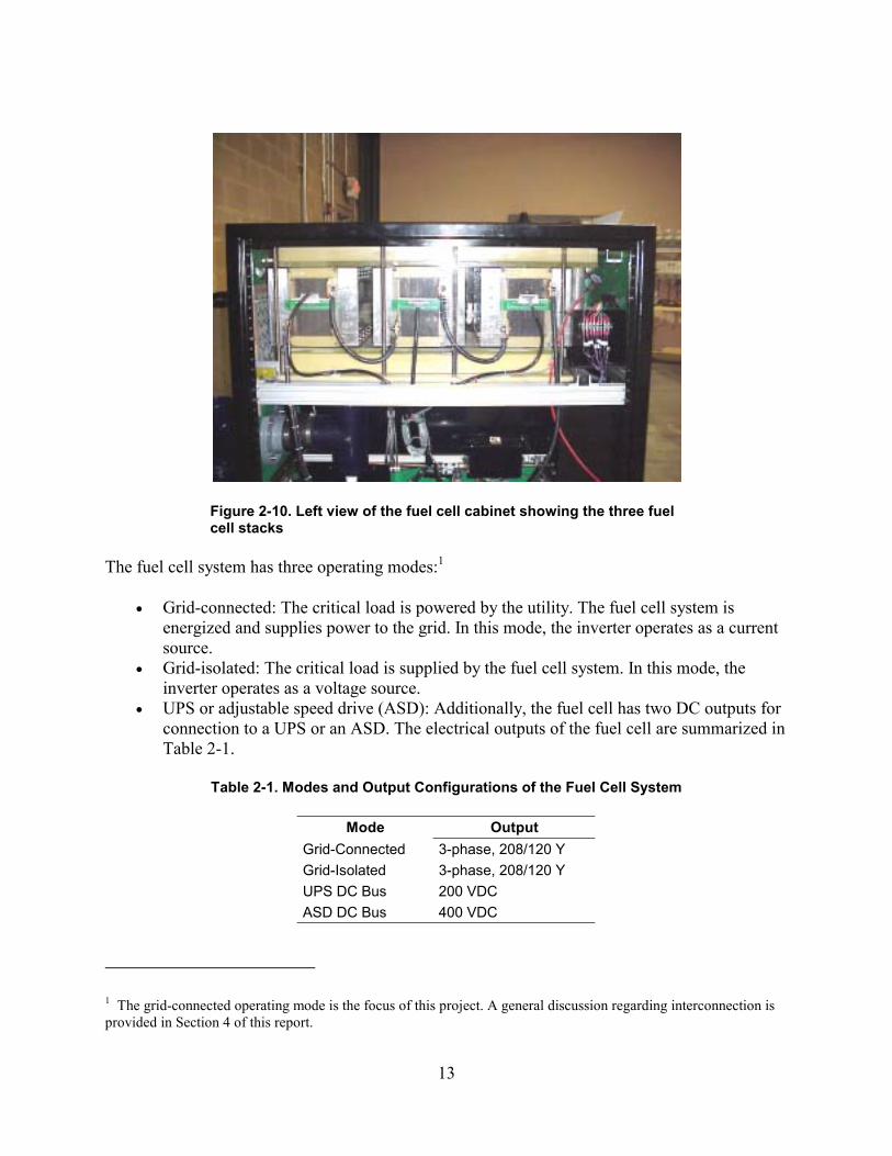
The output power from the system is 3 kW. The three stacks of the fuel cell are designed to supply the 3 kW plus the losses of the power electronics and the power to operate the fuel cell itself. The stacks are shown in Figure 2-10. The stacks are electrically in series, and each produces about 17 V DC. The small circuit board in the middle of each stack allows for monitoring of individual cell voltage.
13
Figure 2-10. Left view of the fuel cell cabinet showing the three fuel cell stacks
The fuel cell system has three operating modes:1
• Grid-connected: The critical load is powered by the utility. The fuel cell system is energized and supplies power to the grid. In this mode, the inverter operates as a current source.
• Grid-isolated: The critical load is supplied by the fuel cell system. In this mode, the inverter operates as a voltage source.
• UPS or adjustable speed drive (ASD): Additionally, the fuel cell has two DC outputs for connection to a UPS or an ASD. The electrical outputs of the fuel cell are summarized in Table 2-1.
Table 2-1. Modes and Output Configurations of the Fuel Cell System
Mode Output Grid-Connected 3-phase, 208/120 Y Grid-Isolated 3-phase, 208/120 Y UPS DC Bus 200 VDC ASD DC Bus 400 VDC
1 The grid-connected operating mode is the focus of this project. A general discussion regarding interconnection is provided in Section 4 of this report.
14
2.1.1 Monitoring Software
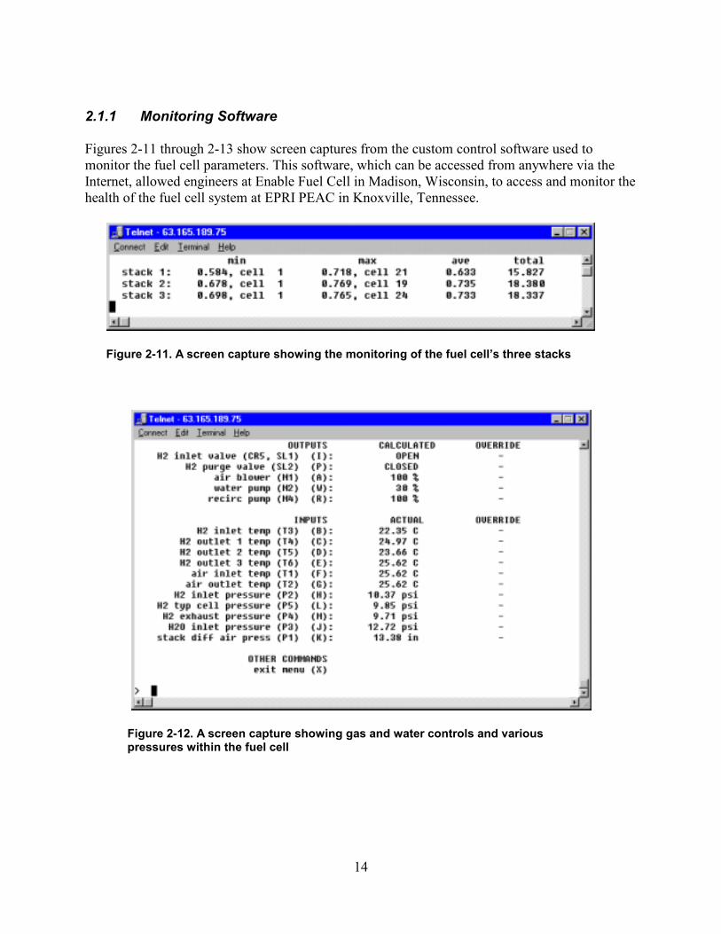
Figures 2-11 through 2-13 show screen captures from the custom control software used to monitor the fuel cell parameters. This software, which can be accessed from anywhere via the Internet, allowed engineers at Enable Fuel Cell in Madison, Wisconsin, to access and monitor the health of the fuel cell system at EPRI PEAC in Knoxville, Tennessee.
Figure 2-11. A screen capture showing the monitoring of the fuel cell’s three stacks
Figure 2-12. A screen capture showing gas and water controls and various pressures within the fuel cell
15
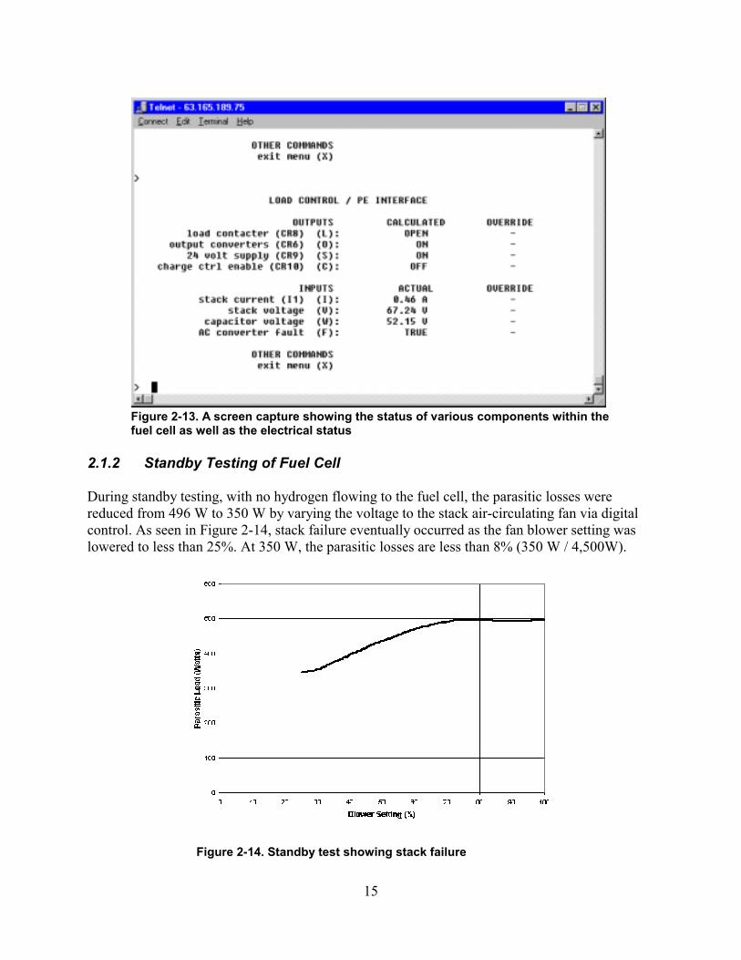
Figure 2-13. A screen capture showing the status of various components within the fuel cell as well as the electrical status
2.1.2 Standby Testing of Fuel Cell
During standby testing, with no hydrogen flowing to the fuel cell, the parasitic losses were reduced from 496 W to 350 W by varying the voltage to the stack air-circulating fan via digital control. As seen in Figure 2-14, stack failure eventually occurred as the fan blower setting was lowered to less than 25%. At 350 W, the parasitic losses are less than 8% (350 W / 4,500W).
Figure 2-14. Standby test showing stack failure
16
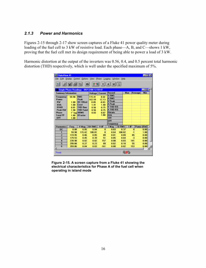
2.1.3 Power and Harmonics
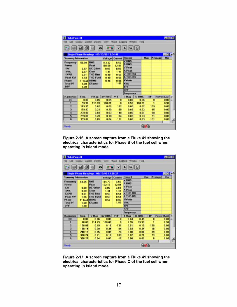
Figures 2-15 through 2-17 show screen captures of a Fluke 41 power quality meter during loading of the fuel cell to 3 kW of resistive load. Each phase—A, B, and C—shows 1 kW, proving that the fuel cell met its design requirement of being able to power a load of 3 kW.
Harmonic distortion at the output of the inverters was 0.56, 0.4, and 0.5 percent total harmonic distortion (THD) respectively, which is well under the specified maximum of 5%.
Figure 2-15. A screen capture from a Fluke 41 showing the electrical characteristics for Phase A of the fuel cell when operating in island mode
17
Figure 2-16. A screen capture from a Fluke 41 showing the electrical characteristics for Phase B of the fuel cell when operating in island mode
Figure 2-17. A screen capture from a Fluke 41 showing the electrical characteristics for Phase C of the fuel cell when operating in island mode
18
2.1.4 Fuel Cell System Output Characteristics
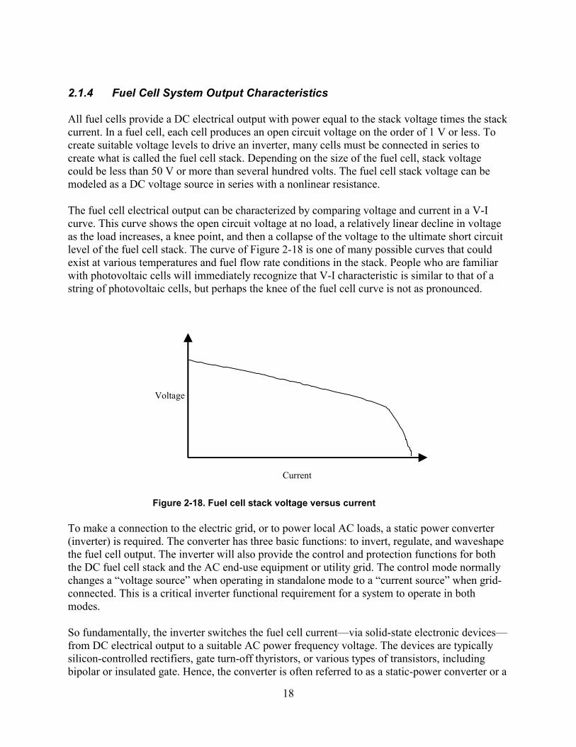
All fuel cells provide a DC electrical output with power equal to the stack voltage times the stack current. In a fuel cell, each cell produces an open circuit voltage on the order of 1 V or less. To create suitable voltage levels to drive an inverter, many cells must be connected in series to create what is called the fuel cell stack. Depending on the size of the fuel cell, stack voltage could be less than 50 V or more than several hundred volts. The fuel cell stack voltage can be modeled as a DC voltage source in series with a nonlinear resistance.
The fuel cell electrical output can be characterized by comparing voltage and current in a V-I curve. This curve shows the open circuit voltage at no load, a relatively linear decline in voltage as the load increases, a knee point, and then a collapse of the voltage to the ultimate short circuit level of the fuel cell stack. The curve of Figure 2-18 is one of many possible curves that could exist at various temperatures and fuel flow rate conditions in the stack. People who are familiar with photovoltaic cells will immediately recognize that V-I characteristic is similar to that of a string of photovoltaic cells, but perhaps the knee of the fuel cell curve is not as pronounced.
Current
Voltage
Figure 2-18. Fuel cell stack voltage versus current
To make a connection to the electric grid, or to power local AC loads, a static power converter (inverter) is required. The converter has three basic functions: to invert, regulate, and waveshape the fuel cell output. The inverter will also provide the control and protection functions for both the DC fuel cell stack and the AC end-use equipment or utility grid. The control mode normally changes a “voltage source” when operating in standalone mode to a “current source” when grid-connected. This is a critical inverter functional requirement for a system to operate in both modes.
So fundamentally, the inverter switches the fuel cell current—via solid-state electronic devices— from DC electrical output to a suitable AC power frequency voltage. The devices are typically silicon-controlled rectifiers, gate turn-off thyristors, or various types of transistors, including bipolar or insulated gate. Hence, the converter is often referred to as a static-power converter or a
19
switch-mode converter. These fuel cell power converters have very similar requirements to those used for photovoltaic and battery energy storage systems. The voltage droop characteristics and range of voltages utilized are somewhat similar, and the protection requirements for the utility grid interconnection are essentially the same.
2.1.5 Performance and Modeling Results
As with any generator, it is important to understand the performance in terms of power and energy. Specifically, what energy can be taken from the system and at what power level? This is important for compatibility with loads. Can the fuel cell supply enough power to start a load such as a motor requiring a high level of inrush current? The objectives of the performance measurements were to characterize the system in terms of its power and energy capability and to relate this performance to practical load applications. Based on the data gathered, a model was developed from which it is possible to base predicted performance.
It was discovered during initial testing that the stack of Enable fuel cells possesses significant internal capacitance. This is loosely equivalent to inertia in an internal combustion engine. The obvious benefit of this is the potential for improvement in the pulse-power capability of the fuel cell. During this phase of the project, it was demonstrated that a fuel cell could respond within minutes, and this suggested the possibly of operating within seconds from a cold start. The data gathered from the performance testing helped to quantify the internal capacitance.
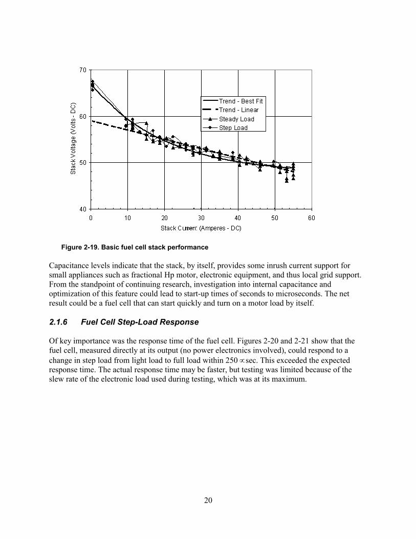
The results from the performance measurements (Figure 2-19) show that, electrically, the fuel cell can be modeled as a current-controlled voltage source in parallel with a capacitance of significant value.
Best Fit V = 47.5 + 19.5 * e-I/20 Linear V = 47.5 - (I * 0.2)
20
Figure 2-19. Basic fuel cell stack performance
Capacitance levels indicate that the stack, by itself, provides some inrush current support for small appliances such as fractional Hp motor, electronic equipment, and thus local grid support. From the standpoint of continuing research, investigation into internal capacitance and optimization of this feature could lead to start-up times of seconds to microseconds. The net result could be a fuel cell that can start quickly and turn on a motor load by itself.
2.1.6 Fuel Cell Step-Load Response
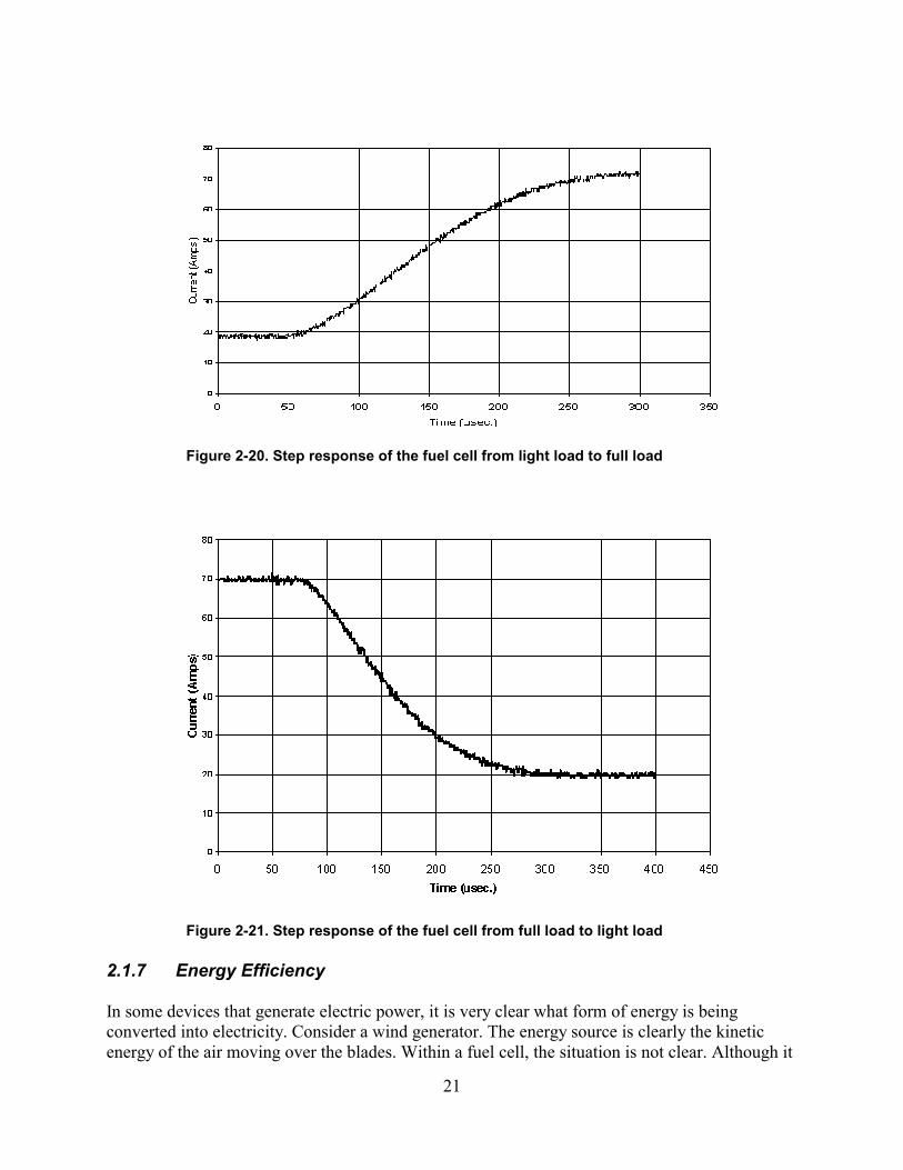
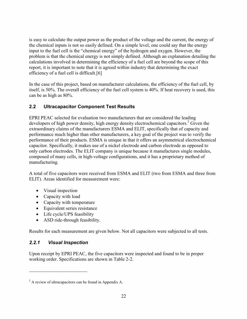
Of key importance was the response time of the fuel cell. Figures 2-20 and 2-21 show that the fuel cell, measured directly at its output (no power electronics involved), could respond to a change in step load from light load to full load within 250 ∝sec. This exceeded the expected response time. The actual response time may be faster, but testing was limited because of the slew rate of the electronic load used during testing, which was at its maximum.
21
Figure 2-20. Step response of the fuel cell from light load to full load
Figure 2-21. Step response of the fuel cell from full load to light load
2.1.7 Energy Efficiency
In some devices that generate electric power, it is very clear what form of energy is being converted into electricity. Consider a wind generator. The energy source is clearly the kinetic energy of the air moving over the blades. Within a fuel cell, the situation is not clear. Although it
22
is easy to calculate the output power as the product of the voltage and the current, the energy of the chemical inputs is not so easily defined. On a simple level, one could say that the energy input to the fuel cell is the “chemical energy” of the hydrogen and oxygen. However, the problem is that the chemical energy is not simply defined. Although an explanation detailing the calculations involved in determining the efficiency of a fuel cell are beyond the scope of this report, it is important to note that it is agreed within industry that determining the exact efficiency of a fuel cell is difficult.[6]
In the case of this project, based on manufacturer calculations, the efficiency of the fuel cell, by itself, is 50%. The overall efficiency of the fuel cell system is 40%. If heat recovery is used, this can be as high as 80%.
2.2 Ultracapacitor Component Test Results
EPRI PEAC selected for evaluation two manufacturers that are considered the leading developers of high power density, high energy density electrochemical capacitors.2 Given the extraordinary claims of the manufacturers ESMA and ELIT, specifically that of capacity and performance much higher than other manufacturers, a key goal of the project was to verify the performance of their products. ESMA is unique in that it offers an asymmetrical electrochemical capacitor. Specifically, it makes use of a nickel electrode and carbon electrode as opposed to only carbon electrodes. The ELIT company is unique because it manufactures single modules, composed of many cells, in high-voltage configurations, and it has a proprietary method of manufacturing.
A total of five capacitors were received from ESMA and ELIT (two from ESMA and three from ELIT). Areas identified for measurement were:
• Visual inspection • Capacity with load • Capacity with temperature • Equivalent series resistance • Life cycle/UPS feasibility • ASD ride-through feasibility.
Results for each measurement are given below. Not all capacitors were subjected to all tests.
2.2.1 Visual Inspection
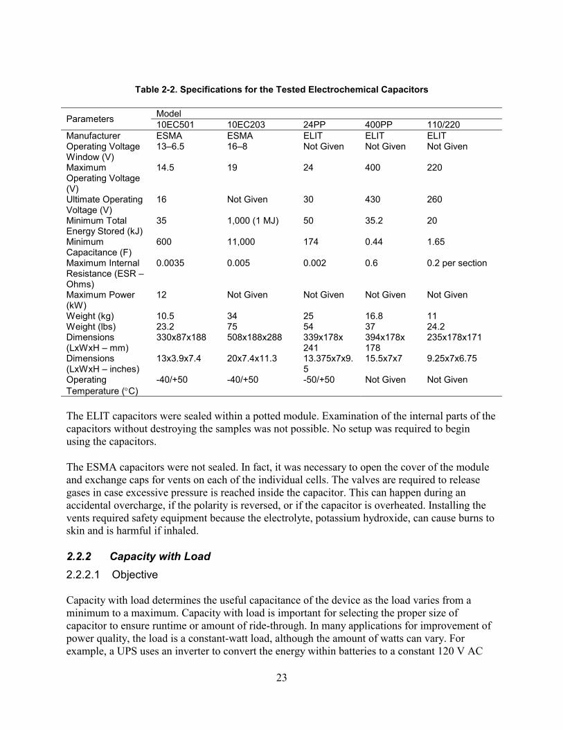
Upon receipt by EPRI PEAC, the five capacitors were inspected and found to be in proper working order. Specifications are shown in Table 2-2.
2 A review of ultracapacitors can be found in Appendix A.
23
Table 2-2. Specifications for the Tested Electrochemical Capacitors
Model Parameters 10EC501 10EC203 24PP 400PP 110/220 Manufacturer ESMA ESMA ELIT ELIT ELIT Operating Voltage Window (V)
13–6.5 16–8 Not Given Not Given Not Given
Maximum Operating Voltage (V)
14.5 19 24 400 220
Ultimate Operating Voltage (V)
16 Not Given 30 430 260
Minimum Total Energy Stored (kJ)
35 1,000 (1 MJ) 50 35.2 20
Minimum Capacitance (F)
600 11,000 174 0.44 1.65
Maximum Internal Resistance (ESR – Ohms)
0.0035 0.005 0.002 0.6 0.2 per section
Maximum Power (kW)
12 Not Given Not Given Not Given Not Given
Weight (kg) 10.5 34 25 16.8 11 Weight (lbs) 23.2 75 54 37 24.2 Dimensions (LxWxH – mm)
330x87x188 508x188x288 339x178x 241
394x178x 178
235x178x171
Dimensions (LxWxH – inches)
13x3.9x7.4 20x7.4x11.3 13.375x7x9.5
15.5x7x7 9.25x7x6.75
Operating Temperature (°C)
-40/+50 -40/+50 -50/+50 Not Given Not Given
The ELIT capacitors were sealed within a potted module. Examination of the internal parts of the capacitors without destroying the samples was not possible. No setup was required to begin using the capacitors.
The ESMA capacitors were not sealed. In fact, it was necessary to open the cover of the module and exchange caps for vents on each of the individual cells. The valves are required to release gases in case excessive pressure is reached inside the capacitor. This can happen during an accidental overcharge, if the polarity is reversed, or if the capacitor is overheated. Installing the vents required safety equipment because the electrolyte, potassium hydroxide, can cause burns to skin and is harmful if inhaled.
2.2.2 Capacity with Load 2.2.2.1 Objective
Capacity with load determines the useful capacitance of the device as the load varies from a minimum to a maximum. Capacity with load is important for selecting the proper size of capacitor to ensure runtime or amount of ride-through. In many applications for improvement of power quality, the load is a constant-watt load, although the amount of watts can vary. For example, a UPS uses an inverter to convert the energy within batteries to a constant 120 V AC
24
output voltage. Similarly, if an electrochemical capacitor is used as a replacement for a battery, the inverter will regulate the discharge voltage of the capacitor to 120 V AC, in effect a constant-watt load. However, the amount of load is a variable because the user may or may not have loads, such as a computer or printer, turned on. For this reason, capacity with various loads was measured.
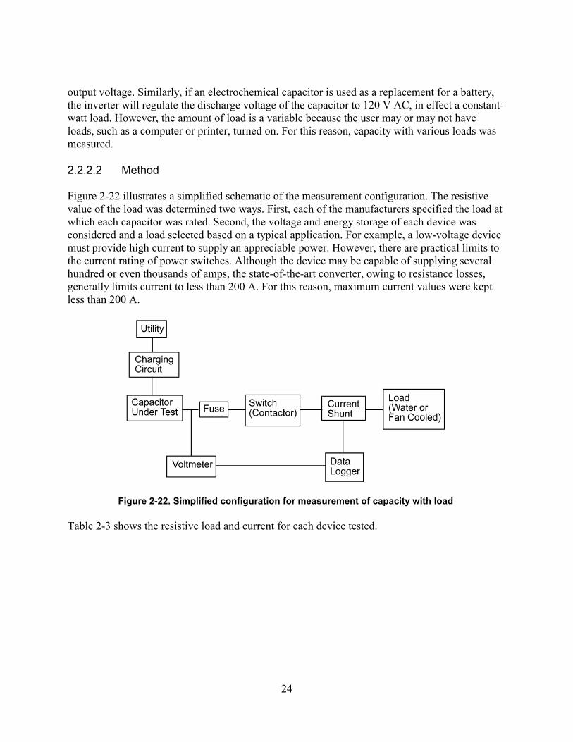
2.2.2.2 Method
Figure 2-22 illustrates a simplified schematic of the measurement configuration. The resistive value of the load was determined two ways. First, each of the manufacturers specified the load at which each capacitor was rated. Second, the voltage and energy storage of each device was considered and a load selected based on a typical application. For example, a low-voltage device must provide high current to supply an appreciable power. However, there are practical limits to the current rating of power switches. Although the device may be capable of supplying several hundred or even thousands of amps, the state-of-the-art converter, owing to resistance losses, generally limits current to less than 200 A. For this reason, maximum current values were kept less than 200 A.
Figure 2-22. Simplified configuration for measurement of capacity with load
Table 2-3 shows the resistive load and current for each device tested.
25
Table 2-3. Load Resistance Used for Measurement of Capacity
Capacitor Resistance (Ohms) Maximum Current (A) Maximum Power (W) 0.1 160 2560 0.2 80 1280 0.3* 53.3 852
ESMA
10EC203 0.8 20 320 0.1 (.06*) 130 1690 0.2 65 845
ESMA
10EC501 1.015 12.8 166 0.2 120 2880 0.8 30 720
ELIT
24PP 10* 2.4 57.6 10 22 48 50 4.4 968
ELIT
110/220PP 180* 1.22 268
*Manufacturer’s specified resistance
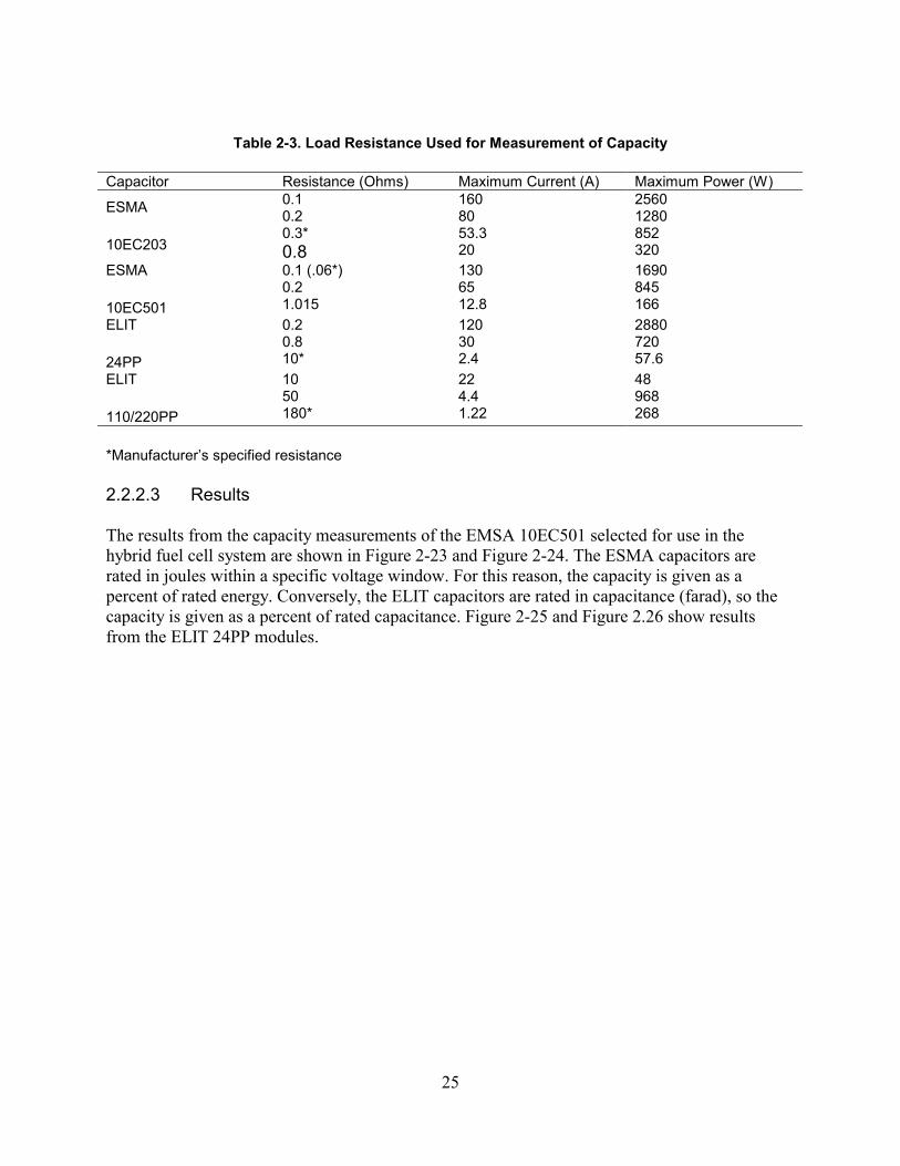
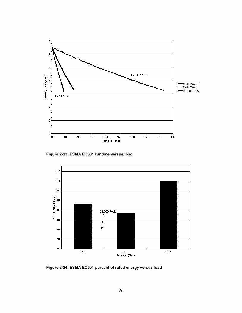
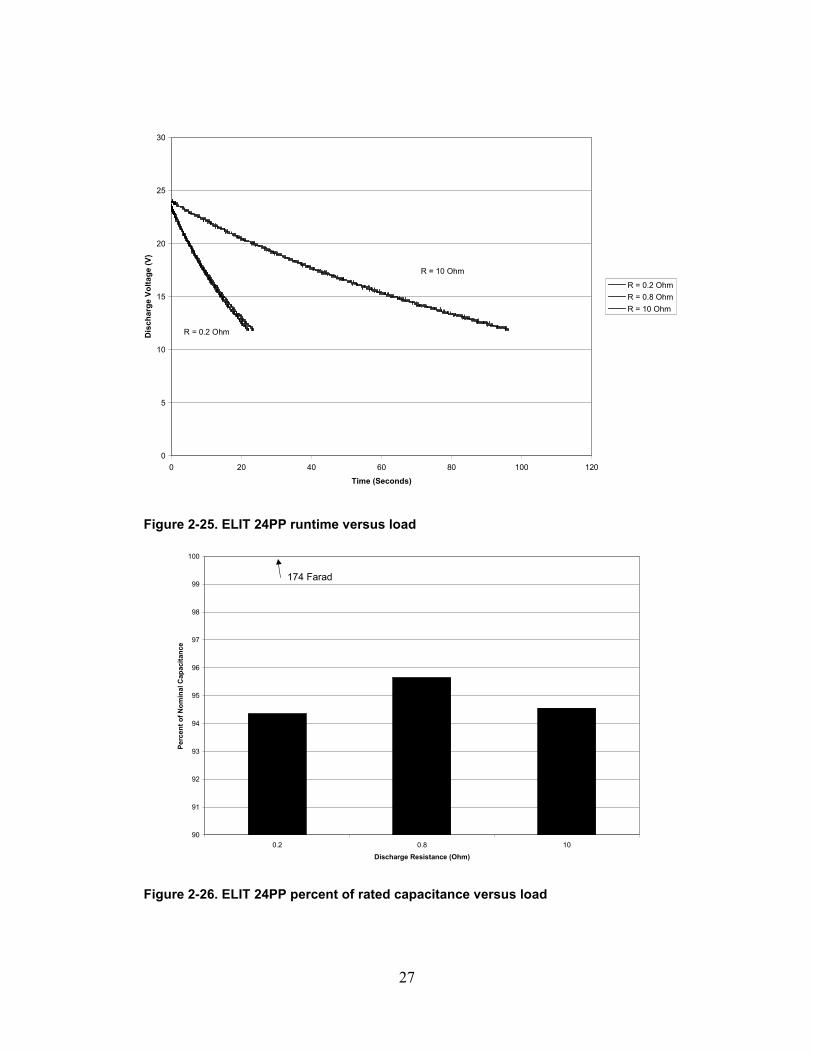
2.2.2.3 Results
The results from the capacity measurements of the EMSA 10EC501 selected for use in the hybrid fuel cell system are shown in Figure 2-23 and Figure 2-24. The ESMA capacitors are rated in joules within a specific voltage window. For this reason, the capacity is given as a percent of rated energy. Conversely, the ELIT capacitors are rated in capacitance (farad), so the capacity is given as a percent of rated capacitance. Figure 2-25 and Figure 2.26 show results from the ELIT 24PP modules.
26
Figure 2-23. ESMA EC501 runtime versus load
Figure 2-24. ESMA EC501 percent of rated energy versus load
27
0
5
10
15
20
25
30
0 20 40 60 80 100 120
Time (Seconds)
Dis
char
ge V
olta
ge (V
)
R = 0.2 OhmR = 0.8 OhmR = 10 Ohm
R = 10 Ohm
R = 0.2 Ohm
Figure 2-25. ELIT 24PP runtime versus load
90
91
92
93
94
95
96
97
98
99
100
0.2 0.8 10
Discharge Resistance (Ohm)
Perc
ent o
f Nom
inal
Cap
acita
nce
174 Farad
Figure 2-26. ELIT 24PP percent of rated capacitance versus load
28
In general, all of the capacitors performed very near the manufacturers’ specified energy or capacitance levels. Both of the ESMA capacitors (EC203 and EC501) exceeded the specification by a few percentage points. These results were very favorable for the new technology units.
2.2.3 Capacity with Temperature 2.2.3.1 Objective
The capacity with temperature determines the useful capacitance of the device as temperature is changed. This is important when considering capacitors for use in uncontrolled environments. Many areas inside a manufacturing facility can reach temperatures above 40°C, and some applications in cold climates may require operation below freezing. Understanding how temperature affects the capacity of the electrochemical capacitor is key to proper sizing and application.
2.2.3.2 Method
The setup for the measurement is the same, except that the capacitors were placed in a thermal chamber. The resistive load was held constant at the value specified by the manufacturer while the temperature was set to –17°C, 0°C, and 40°C. Charge and discharge occurred after the capacitors had stabilized.
2.2.3.3 Results
The results from the capacity measurements with temperature are shown in Figure 2-27 and Figure 2-28. Representative samples of both the ESMA technology and the ELIT technology were used.
29
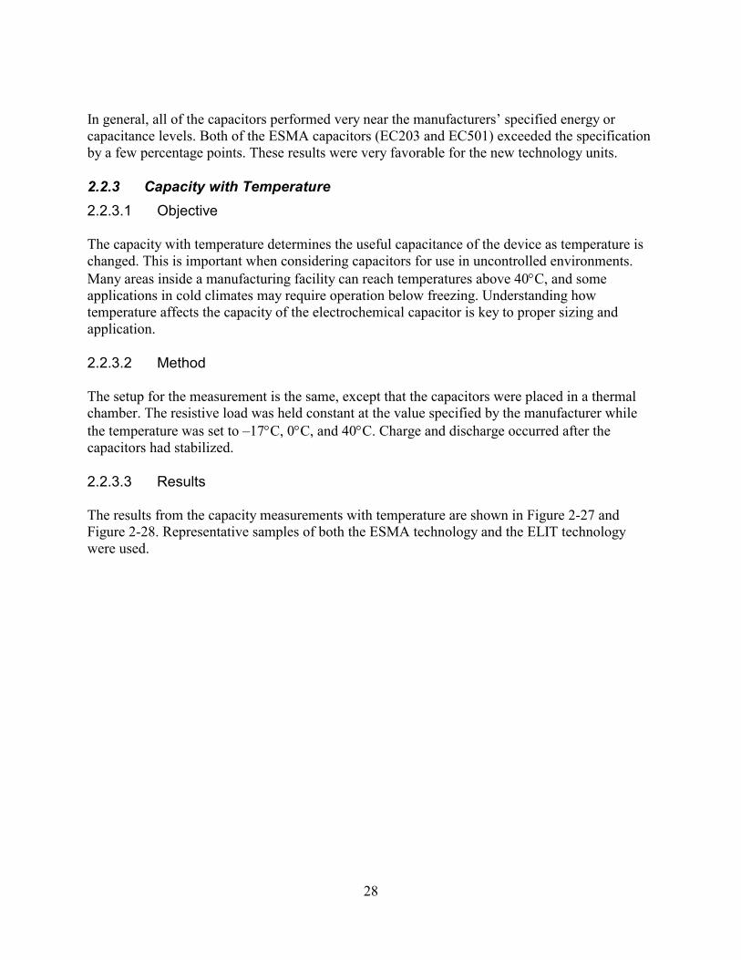
Figure 2-27. ESMA EC203, percent of nominal energy as temperature is varied
The results for the ESMA EC203 capacitor show a definite relationship between energy and temperature. The change is approximated at 1% per degree Celsius. However, it may be possible to compensate for the loss of energy at low temperature by increasing the charge voltage. This is not an uncommon circuit, as many battery chargers offer temperature compensation. Continued discussion with the manufacturer is needed to optimize the design of the capacitor and the charging procedure needed.
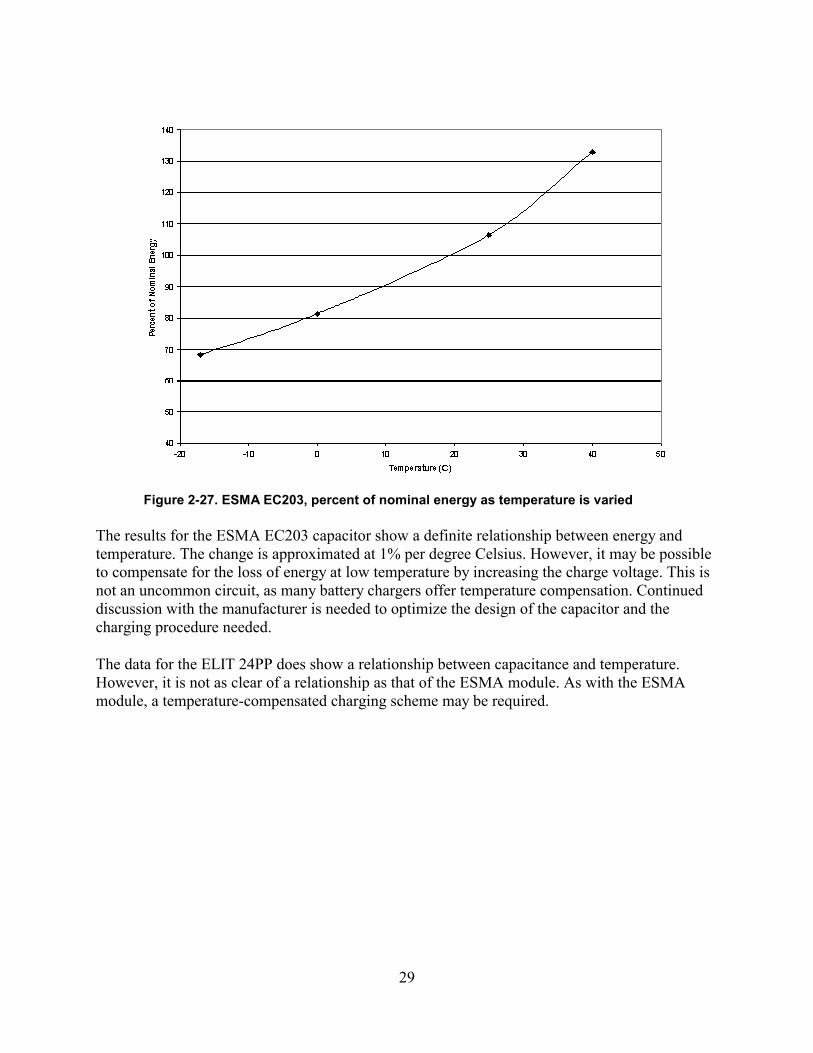
The data for the ELIT 24PP does show a relationship between capacitance and temperature. However, it is not as clear of a relationship as that of the ESMA module. As with the ESMA module, a temperature-compensated charging scheme may be required.
30
Figure 2-28. ELIT 24PP percent of nominal capacitance as temperature is varied
2.2.4 Equivalent Series Resistance 2.2.4.1 Objective
The equivalent series resistance (ESR) is a measure of the lumped resistance of the electrochemical capacitor. A first-order model of an electrochemical capacitor is a capacitor in series with a resistance. Knowing the ESR is important because it determines how fast charge can be drawn and replaced from the capacitor. For example, the short-circuit current of the capacitor is limited by the ESR. In the case of the ESMA EC203, the ESR is specified at less than 0.0035 Ω. A charge of 16 V then equates to a short-circuit current of 4,571 A. Ideally, the lower the ESR the better because during charge and discharge the ESR produces heat.
2.2.4.2 Method
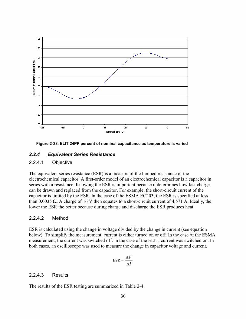
ESR is calculated using the change in voltage divided by the change in current (see equation below). To simplify the measurement, current is either turned on or off. In the case of the ESMA measurement, the current was switched off. In the case of the ELIT, current was switched on. In both cases, an oscilloscope was used to measure the change in capacitor voltage and current.
ESR = IV
∆∆
2.2.4.3 Results
The results of the ESR testing are summarized in Table 2-4.
31
Table 2-4. ESR Measurement Results in Ohms
Module ESMA Specification ELIT Specification EPRI PEAC Result EC203 <0.0035 Ω 0.0032 Ω EC501 <0.005 Ω 0.003 Ω 24PP <0.002 Ω 0.0017 Ω 110/220PP <0.02 Ω/section 0.140 Ω/section
The results show that the ESMA capacitors met the specification with an ESR slightly less than the maximum. One of the ELIT capacitors, the 24PP, met the specification. However, the 110/220PP module did not. A reason for this is the difference in measurement method. ELIT specifies capacitance at 1 kHz. EPRI PEAC used the same method, making or breaking current, for both the ESMA and the ELIT. Even though the result is high, it is a relatively low value for a 220-V capacitor with 20-kJ capability.
2.3 Preliminary System Test Results 2.3.1 Hybrid System Components and Operating Modes
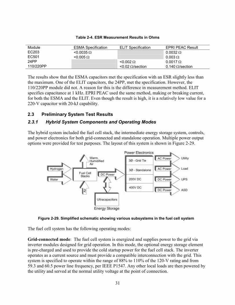
The hybrid system included the fuel cell stack, the intermediate energy storage system, controls, and power electronics for both grid-connected and standalone operation. Multiple power output options were provided for test purposes. The layout of this system is shown in Figure 2-29.
Figure 2-29. Simplified schematic showing various subsystems in the fuel cell system
The fuel cell system has the following operating modes:
Grid-connected mode: The fuel cell system is energized and supplies power to the grid via inverter modules designed for grid operation. In this mode, the optional energy storage element is pre-charged and used to provide the cold startup power for the fuel cell stack. The inverter operates as a current source and must provide a compatible interconnection with the grid. This system is specified to operate within the range of 88% to 110% of the 120-V rating and from 59.3 and 60.5 power line frequency, per IEEE P1547. Any other local loads are then powered by the utility and served at the normal utility voltage at the point of connection.
32
Grid-isolated (standalone) mode: In this mode, the local AC loads are supplied by the fuel cell system via inverter modules operating as a voltage source. The energy storage element provides current for momentary overloads and is charged by the stack during periods of lower local loading. Voltage regulation and frequency limits can be set to meet the specific requirements of the powered equipment or follow the standard for system voltages specified in ANSI C84.1. In any case, the hybrid system operates to provide a compatible source for the end-use equipment.
DC-connected mode: Additionally, the fuel cell has two DC outputs for direct connection to a DC load, such as the DC bus of a UPS or an ASD. In this mode, the hybrid system integrates directly with the specific end-use equipment, providing the full stack power of 4,500 W, and, in this way, eliminates the need for an inverter or any additional equipment for the grid interconnection. Another interesting feature is that the fuel cell and the energy storage element act to provide uninterruptible power to the UPS or ASD loads.
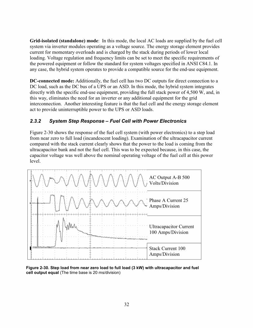
2.3.2 System Step Response – Fuel Cell with Power Electronics
Figure 2-30 shows the response of the fuel cell system (with power electronics) to a step load from near zero to full load (incandescent loading). Examination of the ultracapacitor current compared with the stack current clearly shows that the power to the load is coming from the ultracapacitor bank and not the fuel cell. This was to be expected because, in this case, the capacitor voltage was well above the nominal operating voltage of the fuel cell at this power level.
AC Output A-B 500 Volts/Division
Phase A Current 25 Amps/Division
Ultracapacitor Current 100 Amps/Division
Stack Current 100 Amps/Division
Figure 2-30. Step load from near zero load to full load (3 kW) with ultracapacitor and fuel cell output equal (The time base is 20 ms/division)
33
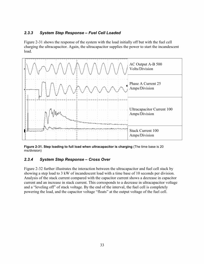
2.3.3 System Step Response – Fuel Cell Loaded
Figure 2-31 shows the response of the system with the load initially off but with the fuel cell charging the ultracapacitor. Again, the ultracapacitor supplies the power to start the incandescent load.
AC Output A-B 500 Volts/Division
Phase A Current 25 Amps/Division
Ultracapacitor Current 100 Amps/Division
Stack Current 100 Amps/Division
Figure 2-31. Step loading to full load when ultracapacitor is charging (The time base is 20 ms/division)
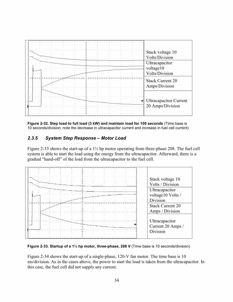
2.3.4 System Step Response – Cross Over
Figure 2-32 further illustrates the interaction between the ultracapacitor and fuel cell stack by showing a step load to 3 kW of incandescent load with a time base of 10 seconds per division. Analysis of the stack current compared with the capacitor current shows a decrease in capacitor current and an increase in stack current. This corresponds to a decrease in ultracapacitor voltage and a “leveling off” of stack voltage. By the end of the interval, the fuel cell is completely powering the load, and the capacitor voltage “floats” at the output voltage of the fuel cell.
34
Stack voltage 10 Volts/Division Ultracapacitor voltage10 Volts/Division Stack Current 20 Amps/Division
Ultracapacitor Current 20 Amps/Division
Figure 2-32. Step load to full load (3 kW) and maintain load for 100 seconds (Time base is 10 seconds/division; note the decrease in ultracapacitor current and increase in fuel cell current)
2.3.5 System Step Response – Motor Load
Figure 2-33 shows the start-up of a 1½ hp motor operating from three-phase 208. The fuel cell system is able to start the load using the energy from the ultracapacitor. Afterward, there is a gradual “hand-off” of the load from the ultracapacitor to the fuel cell.
Stack voltage 10 Volts / Division Ultracapacitor voltage10 Volts / Division Stack Current 20 Amps / Division
Ultracapacitor Current 20 Amps / Division
Figure 2-33. Startup of a 1½ hp motor, three-phase, 208 V (Time base is 10 seconds/division)
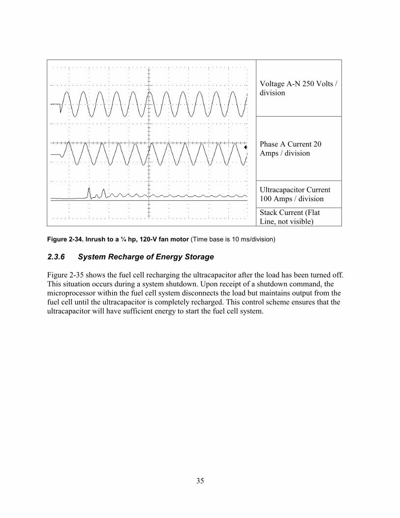
Figure 2-34 shows the start-up of a single-phase, 120-V fan motor. The time base is 10 ms/division. As in the cases above, the power to start the load is taken from the ultracapacitor. In this case, the fuel cell did not supply any current.
35
Voltage A-N 250 Volts / division
Phase A Current 20 Amps / division
Ultracapacitor Current 100 Amps / division
Stack Current (Flat Line, not visible)
Figure 2-34. Inrush to a ¼ hp, 120-V fan motor (Time base is 10 ms/division)
2.3.6 System Recharge of Energy Storage
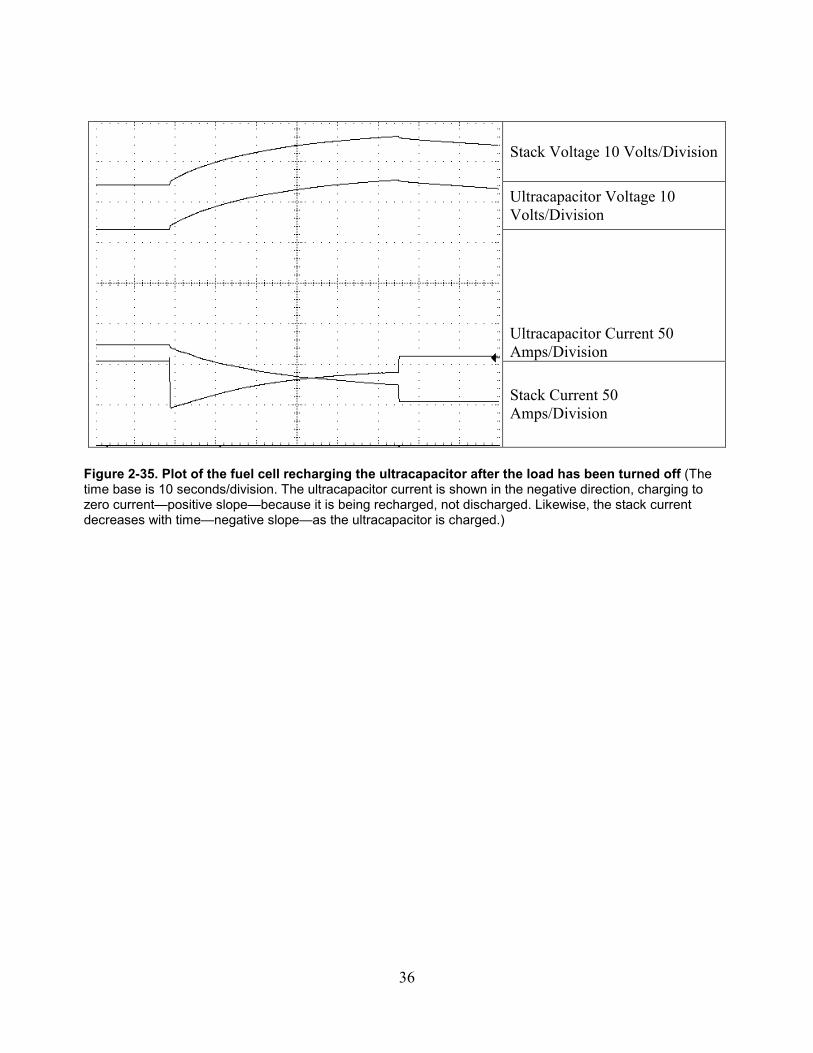
Figure 2-35 shows the fuel cell recharging the ultracapacitor after the load has been turned off. This situation occurs during a system shutdown. Upon receipt of a shutdown command, the microprocessor within the fuel cell system disconnects the load but maintains output from the fuel cell until the ultracapacitor is completely recharged. This control scheme ensures that the ultracapacitor will have sufficient energy to start the fuel cell system.
36
Stack Voltage 10 Volts/Division
Ultracapacitor Voltage 10 Volts/Division
Ultracapacitor Current 50 Amps/Division
Stack Current 50 Amps/Division
Figure 2-35. Plot of the fuel cell recharging the ultracapacitor after the load has been turned off (The time base is 10 seconds/division. The ultracapacitor current is shown in the negative direction, charging to zero current—positive slope—because it is being recharged, not discharged. Likewise, the stack current decreases with time—negative slope—as the ultracapacitor is charged.)
37
3. Hybrid System Design
3.1 Hybrid System Design Objective
The hybrid technology system combines a fuel cell with on-board energy storage as a short-term source of current and for stabilization. The storage element will be able to both absorb and inject high power as needed to stabilize the fuel cell response to power system variations and to allow load following when disconnected from the power grid. A properly designed hybrid system, matching the fuel cell and storage elements with inverter control, will be able to provide a fast response where the fuel cell alone is limited to rated current. A typical hybrid power system will need only a few seconds of stored energy to fulfill most operating requirements, such as response to momentary voltage changes and for motor starting. This hybrid approach is suitable for other distributed energy resource (DER) prime movers, including photovoltaic cells, microturbines, small wind turbines, and internal combustion engines.
3.2 Prime Mover Specification (Fuel Cell with Power Electronics) 3.2.1 Fuel Cell Technology Selection
In 1996 and 1997, Mahlon S. Wilsonwhile working at Los Alamos National Laboratory (LANL)developed a smaller, simpler class of fuel cells that relies on ambient air pressure for oxygen and on its own water generation for humidification rather than the pumps and fans needed in other types of fuel cell technologies. Mr. Wilson improved PEM technology by designing a round fuel cell stack in which hydrogen is delivered through a central tube that also houses the bolt that holds the stack assembly together. This design is smaller, lighter, and easier to fabricate than rectangular PEM fuel cells, and it is also more efficient because it leaves the entire exposed surface of the cell open for ambient oxygen intake and heat dissipation. It also more efficiently retains water, the reaction product, to prevent dehydration of the cell. The circular fuel cell can be packaged as a D-cell battery-sized stack combined with a metal hydride canister that will last more than three times as long as a comparably sized pack of nickel-cadmium batteries. The cells also can be easily ganged together for higher-power applications.
In 1998, DCH Technology Inc. successfully negotiated a Cooperative Research and Development Agreement and exclusive license agreement with LANL for the "air-breathing PEM fuel cell" patented by Mr. Wilson, LANL, and DOE. DCH Technology Inc. conducts this activity today through its wholly owned subsidiary, the Enable™ Fuel Cell Corp.[4]
Building on this technology, Enable Fuel Cell Corp. developed a system based on an atmospheric pressure stack using low-cost components to create a fuel cell that has parasitic losses of less than 5%. This compares favorably with other systems that use relatively large compressors and have parasitic losses of approximately 20%. Further advances include the use of liquid water, which allows operation with a dry air stream at
38
atmospheric pressure, and an air-cooled stack, which eliminates the need for fans and further reduces parasitic losses.
EPRI PEAC worked with Enable Fuel Cell to explore the application of this advanced technology to power quality applications. It became clear that the technology, because of its simple control strategy, could quickly respond to changes in load. Based on this, a decision was made to order a system from Enable Fuel Cell.
3.2.2 Specification of Fuel Cell and Power Electronics 3.2.2.1 General Applicability
The PEM fuel cell operates on hydrogen, water, and oxygen from air. The prototype system delivered to EPRI PEAC for evaluation was designed to operate from hydrogen tanks. A natural-gas reformer has not been available for this unit. The output power from the system is 3 kW in a grid-connected mode and 6 kW in a standalone mode. The three stacks of the fuel cell are designed to supply the 3 kW plus the losses of the power electronics and the power to operate the fuel cell itself. These specifications describe the generic requirements for a hybrid fuel cell system designed for integration into any of the following systems:
• Grid-connected (focus of this project) • Off-line load following • ASD (optional mode) • On-line UPS (optional mode) • Line-interactive UPS (optional mode).
The electrical outputs of the fuel cell power electronics are summarized in Table 3-1.
Table 3-1. Modes and Output Configurations for the Fuel Cell System
Mode Output Grid-Connected 3-phase, 208/120 Y
Grid-Isolated 3-phase, 208/120 Y
UPS DC Bus 200 V DC
ASD DC Bus 400 V DC
3.2.2.2 Materials and Equipment
All materials and equipment shall be in conformance with electrical and safety codes which are applicable to the installation. The system shall be compliant with the available

39
space and floor loading conditions at the site. It shall include all equipment to properly interface to a natural gas fuel source, DC load, and AC load.
3.2.2.3 Applicable Standards
The hybrid fuel cell shall comply with the following standards, as applicable:
• National Electrical Code (NFPA 70) • OSHA • Standards and specifications of specific manufacturer.
3.2.2.4 Environmental Conditions
The fuel cell shall be able to withstand the following environmental conditions without damage or degradation of operating characteristics:
• Ambient temperature. The system is designed to operate indoors; Storage/transport -20º to +70º C (before water is added).
Note: The main constraint to outdoor use is the tap water used to hydrate the cell membranes. This feature restricts the environmental conditions under which the fuel cell can operate. If intended for applications in cold climates, measures will be necessary to protect the fuel cell from freezing temperatures. Freezing of the fuel cell would result in catastrophic damage. Initially, a temperature range of 0–50°C was requested from the manufacturer. However, after discussion, it was decided that the cost for this feature outweighed the benefit at this time. The reason for this is the use of water within the fuel cell itself. Although not a problem at higher temperatures, when the temperature drops below freezing, there is a real possibility of ice forming within the stack, which would be catastrophic. This situation is not unique to the technology used for this project but is an issue with all PEM-type fuel cells. For a distributed generation application, one could make an argument that the fuel cell will always be operating and generating its own heat, which would prevent damage from ice.
• Relative humidity. 0–90% non-condensing • Altitude. Operating to 4,000 ft. above mean sea level without derating;
storage/transport to 40,000 ft. above mean sea level or as stated by the vendor for transport.
3.2.2.5 Interface with Building Utilities
Electrical, gas, and mechanical connection requirements are to be described by the manufacturer’s installation instructions.
40
3.2.2.6 Output Power
The system output power shall be 3 kW continuous in any mode and shall be incrementally adjustable from 0 to 3 kW.
3.2.2.7 Output Voltage
The fuel cell system shall have three output voltages:
1) 200 V DC 2) 400 V DC 3) 208Y/120 V AC, 3 Phase, 4 Wire, 60 Hz.
The 200 V DC and 400 V DC outputs will be via a selectable switch. Only one output will be required at any given time. Provisions will be made so that the system can be tested as a DC bus source or as an AC source. The inverter (AC) portion of the fuel cell system shall operate in an island (independent mode, voltage source) or grid connected mode (like a photovoltaic inverter, current source).
3.2.2.8 Efficiency
The efficiency of the fuel cell with power electronics is targeted for 25–30%.
3.2.2.9 Protection
The DC output of the fuel cell shall be protected from reverse polarity, reverse power flow, and from a short circuit condition. An automatic circuit breaker will be provided at the DC output, with visible indication that the state is either on or off. The AC output shall be protected from reverse power flow and from a short circuit condition.
3.2.2.10 Hydrogen Gas Safety Alarms
A zonal leak detector for H2 set below the lower flammable limit (LEL) of H2 will be provided as part of the system and installed to operate an audio alarm.
3.2.2.11 Voltage Regulation
The DC output voltage shall be regulated to within ±0.5% for load variations between 0 and 100% and step loads of 20%, 50%, 75%, and 100%. The AC output voltage shall be regulated to within ±2% for steady-state loads and transient loads such as a step load from 0 to 100%.
41
3.2.2.12 Harmonic Distortion
The total harmonic distortion of the output current shall be less than 5% when feeding a utility grid with grid voltage distortion of less than 3%. The output voltage shall be less than 5% THD when serving a linear, or resistive load, in a standalone operating mode.
3.2.2.13 Power Factor
The AC output shall be able to supply loads with power factors from 0 to 1, leading or lagging. Additionally, the system shall be compatible with power factor corrected loads.
3.2.2.14 Frequency Regulation
The frequency regulation in standalone mode shall be ±0.1 Hz. In grid-connected mode the hybrid system frequency will follow the utility frequency.
3.2.2.15 Overload Condition
A momentary overload condition of 200% can be served without operation of any protective system. A sustained overload will be handled safely without damage to the fuel cell system.
3.2.2.16 Dynamic Response
Connection to the electric grid is not required to start the system. The fuel cell shall be capable of changing from no load to full load and from full load to no load within 4 minutes. This dynamic response will be sustained over a period of 1 minute during which multiple discharges or load variations are expected.
3.2.2.17 Storage Recharge Time
The recharge time is a function of the intermediate storage capacity, as determined by the selected vendor.
3.2.2.18 Grounding
Provision for grounding the fuel cell system to a common point shall be provided. The DC output, both positive (+) and negative (-) leads, shall be isolated from the chassis (1,000 V minimum). The AC output shall have provision for a neutral-to-ground bond.
3.2.2.19 Audible Noise
Noise generated under any operating mode shall be less than 55 dBA when measured 3 ft from any side of the fuel cell system.
42
3.3 Energy Storage Component Specification
The following important factors were considered in the design and integration of the energy-storage element:
• Availability • Cost • Design complexity/voltage range • Efficiency • Cycle life • Temperature range • Energy density • Power density • Self-discharge rate • Equalization • Recharge rate of storage element • Excess discharge • Environmental friendliness.
3.3.1 Energy Storage Technology Selection
Table 3-2 compares the relative merits of several energy storage technologies that might typically be used with a fuel cell to provide short-term energy support. A relative comparison of size, availability, cost, efficiency, etc., is provided. For energy storage technology, the energy and power per unit weight or per unit volume are also important parameters for comparison.
The most readily available, lowest cost, and simplest option is the lead-acid battery. The battery is also readily available in a desired size range. However, temperature sensitivity, maintenance requirements, and limited cycle life make the lead-acid battery less interesting for short-term energy applications. Applications that require frequent cycling and long life favor the use of a high cycle-life device such as the electrochemical capacitor or the electrolytic capacitor—devices that also have lower maintenance requirements.
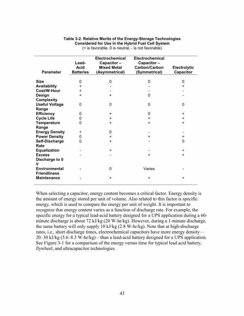
43
Table 3-2. Relative Merits of the Energy-Storage Technologies Considered for Use in the Hybrid Fuel Cell System
(+ is favorable, 0 is neutral, - is not favorable)
Parameter
Lead-Acid
Batteries
Electrochemical Capacitor – Mixed Metal
(Asymmetrical)
Electrochemical Capacitor –
Carbon/Carbon (Symmetrical)
Electrolytic Capacitor
Size 0 0 0 0 Availability + - - + Cost/W-Hour + - - - Design Complexity
+ + 0 -
Useful Voltage Range
0 0 0 0
Efficiency 0 + 0 + Cycle Life 0 + + + Temperature Range
0 + + +
Energy Density + 0 - - Power Density 0 + + + Self-Discharge Rate
0 + - 0
Equalization - + - + Excess Discharge to 0 V
- - + +
Environmental Friendliness
- 0 Varies -
Maintenance - + + +
When selecting a capacitor, energy content becomes a critical factor. Energy density is the amount of energy stored per unit of volume. Also related to this factor is specific energy, which is used to compare the energy per unit of weight. It is important to recognize that energy content varies as a function of discharge rate. For example, the specific energy for a typical lead-acid battery designed for a UPS application during a 60-minute discharge is about 72 kJ/kg (20 W-hr/kg). However, during a 1-minute discharge, the same battery will only supply 10 kJ/kg (2.8 W-hr/kg). Note that at high-discharge rates, i.e., short discharge times, electrochemical capacitors have more energy density—20–30 kJ/kg (5.6–8.3 W-hr/kg)—than a lead-acid battery designed for a UPS application. See Figure 3-1 for a comparison of the energy versus time for typical lead acid battery, flywheel, and ultracapacitor technologies.
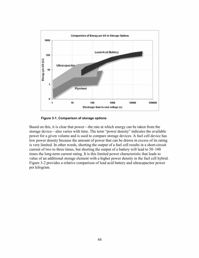
44
Figure 3-1. Comparison of storage options
Based on this, it is clear that power—the rate at which energy can be taken from the storage device—also varies with time. The term “power density” indicates the available power for a given volume and is used to compare storage devices. A fuel cell device has low power density because the amount of power that can be drawn in excess of its rating is very limited. In other words, shorting the output of a fuel cell results in a short-circuit current of two to three times, but shorting the output of a battery will lead to 50–100 times the long-term current rating. It is this limited power characteristic that leads to value of an additional storage element with a higher power density in the fuel cell hybrid. Figure 3-2 provides a relative comparison of lead acid battery and ultracapacitor power per kilogram.
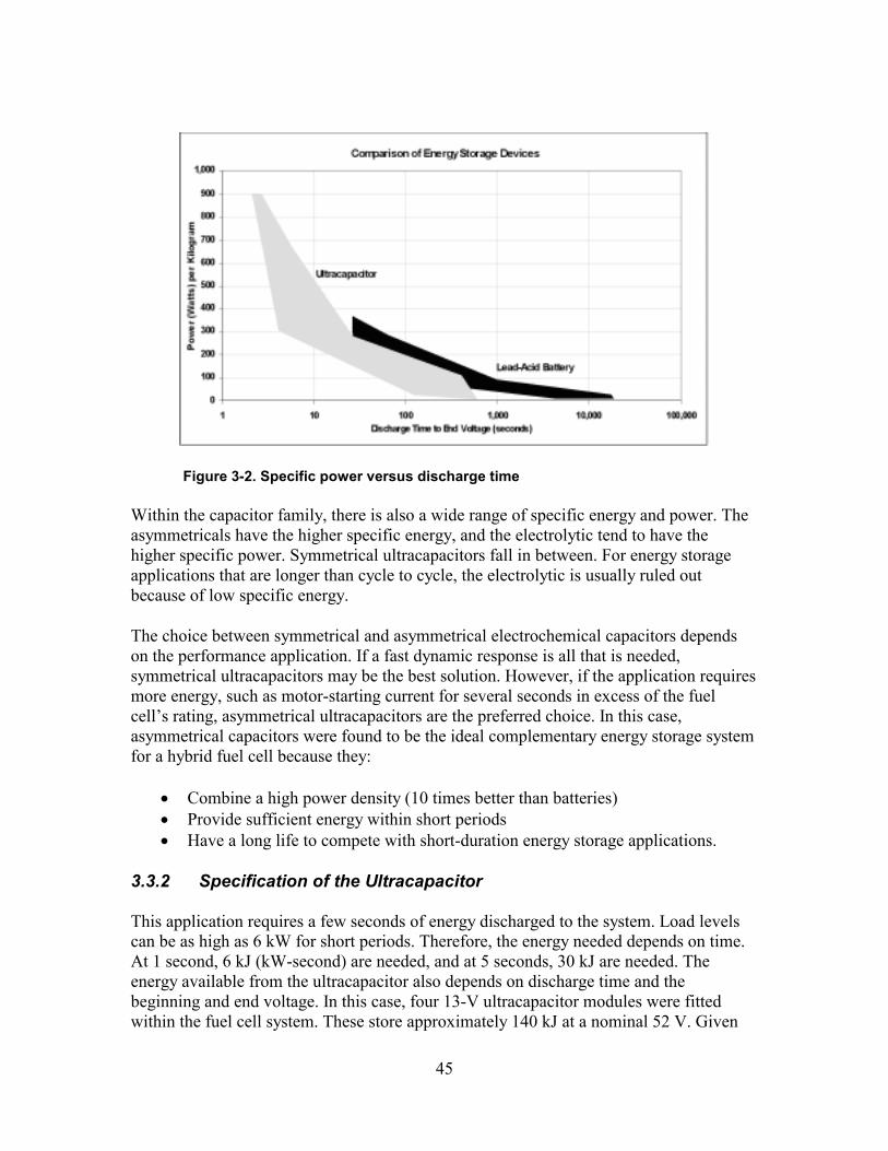
45
Figure 3-2. Specific power versus discharge time
Within the capacitor family, there is also a wide range of specific energy and power. The asymmetricals have the higher specific energy, and the electrolytic tend to have the higher specific power. Symmetrical ultracapacitors fall in between. For energy storage applications that are longer than cycle to cycle, the electrolytic is usually ruled out because of low specific energy.
The choice between symmetrical and asymmetrical electrochemical capacitors depends on the performance application. If a fast dynamic response is all that is needed, symmetrical ultracapacitors may be the best solution. However, if the application requires more energy, such as motor-starting current for several seconds in excess of the fuel cell’s rating, asymmetrical ultracapacitors are the preferred choice. In this case, asymmetrical capacitors were found to be the ideal complementary energy storage system for a hybrid fuel cell because they:
• Combine a high power density (10 times better than batteries) • Provide sufficient energy within short periods • Have a long life to compete with short-duration energy storage applications.
3.3.2 Specification of the Ultracapacitor
This application requires a few seconds of energy discharged to the system. Load levels can be as high as 6 kW for short periods. Therefore, the energy needed depends on time. At 1 second, 6 kJ (kW-second) are needed, and at 5 seconds, 30 kJ are needed. The energy available from the ultracapacitor also depends on discharge time and the beginning and end voltage. In this case, four 13-V ultracapacitor modules were fitted within the fuel cell system. These store approximately 140 kJ at a nominal 52 V. Given
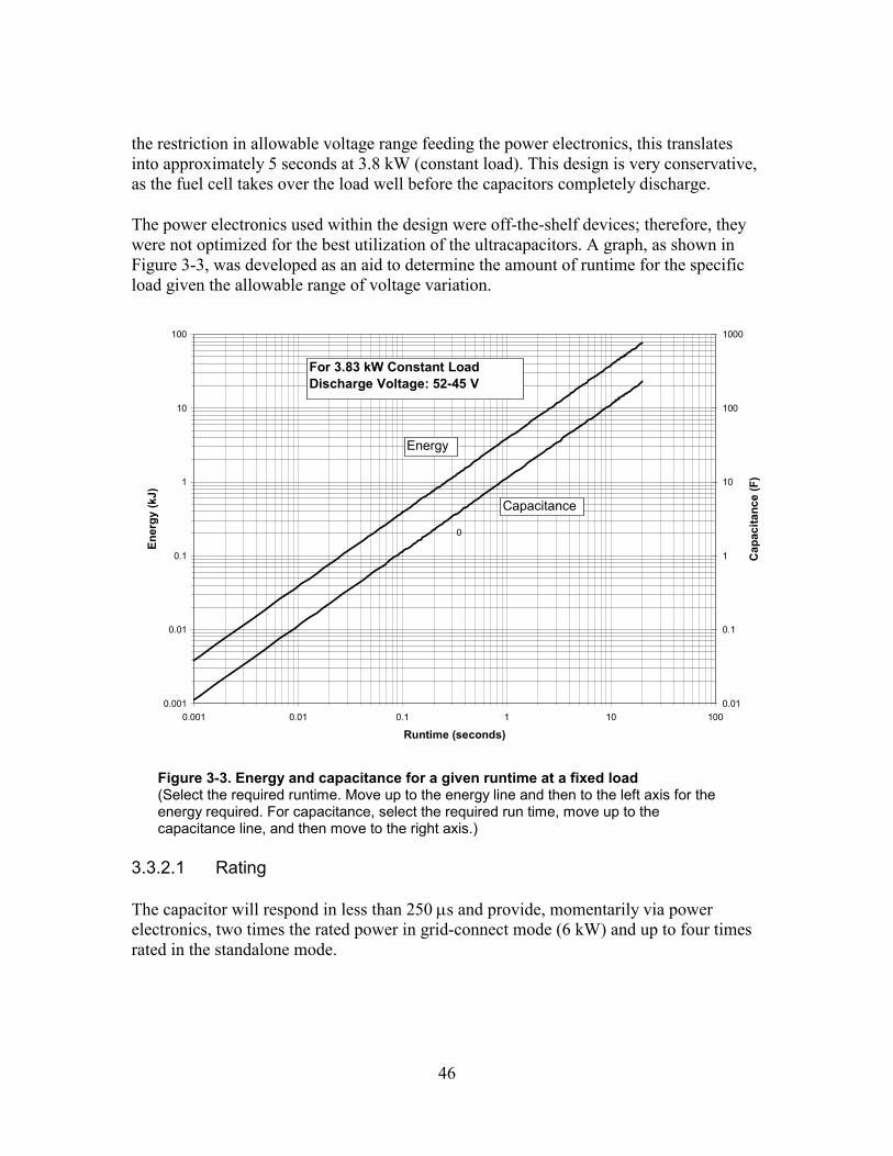
46
the restriction in allowable voltage range feeding the power electronics, this translates into approximately 5 seconds at 3.8 kW (constant load). This design is very conservative, as the fuel cell takes over the load well before the capacitors completely discharge.
The power electronics used within the design were off-the-shelf devices; therefore, they were not optimized for the best utilization of the ultracapacitors. A graph, as shown in Figure 3-3, was developed as an aid to determine the amount of runtime for the specific load given the allowable range of voltage variation.
0.001
0.01
0.1
1
10
100
0.001 0.01 0.1 1 10 100
Runtime (seconds)
Ener
gy (k
J)
0.01
0.1
1
10
100
1000
Cap
acita
nce
(F)
Capacitance
Energy
0
For 3.83 kW Constant LoadDischarge Voltage: 52-45 V
Figure 3-3. Energy and capacitance for a given runtime at a fixed load (Select the required runtime. Move up to the energy line and then to the left axis for the energy required. For capacitance, select the required run time, move up to the capacitance line, and then move to the right axis.)
3.3.2.1 Rating
The capacitor will respond in less than 250 µs and provide, momentarily via power electronics, two times the rated power in grid-connect mode (6 kW) and up to four times rated in the standalone mode.
47
3.3.2.2 Size
The smaller the storage element, the better it will be for cost-effective packaging. However, it is important to point out that the current requirements need to be met, or the fuel cell voltage will collapse and loads may stall during start-up. A momentary level of 100–200 A is not uncommon in residential applications. Generally, the packaging is dictated by the mechanics of the interconnection. Also, if the element is so large that more than a few inches of lead length are used to connect the element to the power-electronic switches, electrolytic capacitors or large snubbers will be needed, which increases cost and decreases efficiency.
3.3.2.3 Availability
As DER increase in market size, so, too, must the availability of the energy source. Lead-acid batteries and electrolytic capacitors are readily available. Electrochemical capacitors are not yet readily available.
3.3.2.4 Design Complexity/Useful Voltage Range
Design complexity defines the cost to integrate the energy-storage element into the system and answers the question “Is the energy in a form that is useful, or are power electronics required to convert the stored energy to the proper voltage and current levels for the application?” An important consideration is the trade-off between depth of discharge, which determines the quality and rating of power-electronic switches, and the number of storage elements placed in parallel.
Design complexity is closely related to the voltage range at which the energy is available. The cost of power electronics is driven upward with decreasing voltage and increasing current, while the cost of the energy source is generally driven upward with increasing voltage and decreasing internal resistance.
3.3.2.5 Roundtrip Charge/Discharge Efficiency
There is a cost associated with the charge/discharge efficiency, which is a function of the ESR and charge acceptance of the device. A lead-acid battery typically requires 30% more energy to charge than it stores. Capacitors require much less, with electrolytic being the best.
3.3.2.6 Cycle Life
Cycle life is the number of charge/discharges that the storage element can survive. It is important to point out that cycle life may be affected by depth and duration of discharge. For example, a lead-acid battery will have a higher cycle life when tested with shallow or slow discharges. However, the cycle life of electrolytic capacitors and electrochemical capacitors are not, in general, affected by depth or duration of discharge.
48
3.3.2.7 Temperature Range
The temperature requirement for the storage element is bounded by other system components: the fuel cell on the low end and the power electronics on the high end. On the low end, because the byproduct of hydrogen/oxygen fuel cells is water, care must be taken to avoid freezing temperatures. On the high end, the power switches in the inverter are limited thermally by the heat sink design. It is common practice to use either 40ºC or 50ºC as the upper boundary of the ambient temperature.
3.3.2.8 Self-Discharge Rate
The self-discharge rate describes the rate at which energy is lost within the storage element as a result of parasitic losses. A high self-discharge rate will increase design complexity by requiring an additional circuit to maintain a typically small but constant flow of energy to the element.
3.3.2.9 Equalization
Cells are placed electrically in series to produce the voltage required for a particular application. During discharge, depending on the condition of each individual cell, an imbalance between cells can occur. If this situation is not corrected in time, it is possible for a single cell to completely discharge, and instead of producing energy, the cell will accept energy. Equalization is a process to ensure that all cells contain approximately the same amount of energy. Equalizing the energy-storage element increases design complexity.
3.3.2.10 Recharge Rate of Storage Element
A design concern is the recharge rate of the electrochemical capacitor. At present, the fuel cell can supply only limited power in excess of rating. Given this, the recharge of the capacitor, even if only a few seconds, may limit the maximum rating of the system. In the future, if necessary, it may be possible to design an active recharge system that varies recharge time as a function of load.
3.3.2.11 Excess Discharge
During maintenance and for safety, it is desirable to eliminate all potential sources of energy. Batteries and mixed-metal capacitors cannot be completely discharged without damage. Electrolytic capacitors and carbon/carbon capacitors can be completely discharged.
3.4 System Design Summary
The fuel cell is a PEM type with the reactants of hydrogen and oxygen in air. Power electronics are provided using off-the-shelf modules designed for general electronic
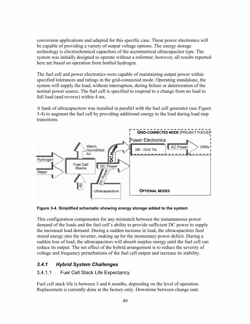
49
conversion applications and adapted for this specific case. These power electronics will be capable of providing a variety of output voltage options. The energy storage technology is electrochemical capacitors of the asymmetrical ultracapacitor type. The system was initially designed to operate without a reformer; however, all results reported here are based on operation from bottled hydrogen.
The fuel cell and power electronics were capable of maintaining output power within specified tolerances and ratings in the grid-connected mode. Operating standalone, the system will supply the load, without interruption, during failure or deterioration of the normal power source. The fuel cell is specified to respond to a change from no load to full load (and reverse) within 4 ms.
A bank of ultracapacitors was installed in parallel with the fuel cell generator (see Figure 3-4) to augment the fuel cell by providing additional energy to the load during load step transitions.
OPTIONAL MODES
GRID-CONNECTED MODE (PROJECT FOCUS)
Figure 3-4. Simplified schematic showing energy storage added to the system
This configuration compensates for any mismatch between the instantaneous power demand of the loads and the fuel cell’s ability to provide sufficient DC power to supply the increased load demand. During a sudden increase in load, the ultracapacitors feed stored energy into the inverter, making up for the momentary power deficit. During a sudden loss of load, the ultracapacitors will absorb surplus energy until the fuel cell can reduce its output. The net effect of the hybrid arrangement is to reduce the severity of voltage and frequency perturbations of the fuel cell output and increase its stability.
3.4.1 Hybrid System Challenges 3.4.1.1 Fuel Cell Stack Life Expectancy
Fuel cell stack life is between 3 and 6 months, depending on the level of operation. Replacement is currently done at the factory only. Downtime between change outs
50
reduces availability and system reliability. This maintenance/repair requirement is not acceptable for most potential system owners. Substantial improvements need to be made in the stack life and ancillary equipment reliability. It should be noted that current systems operated alone without the utility for backup are not as reliable as utility power. A stack life of 40,000 hours is a good near-term objective for all fuel cells as identified by DOE; however, it is not the only factor and may not be long enough. Fuel cells have pumps, fans, inverters, and other ancillary devices. The whole system must not shut down more than a few hours per year, or it will be less reliable than utility power.
3.4.1.2 Inverter Voltage Operating Range
One limitation of the system design is the voltage operating range of the off-the-shelf inverter, which was designed for lead-acid batteries rather than for fuel cells or ultracapacitors. As a result, the energy utilization of the electrochemical capacitors and fuel cells will remain less than optimal until inverter designs are optimized. On the other hand, the development of custom power electronics for this application is expensive, and given problems with fuel cell cost and life, most companies are not investing in custom power electronics.
3.4.1.3 Load Current Demands
In an ideal scenario, the energy-storage element would not be needed, given the fast response of the fuel cell. However, most appliances and industrial commercial equipment are designed to expect a fairly “stiff” voltage source. In this scenario, equipment can demand a momentary high current for starting or changing operating modes. Currents provide both real and reactive power to meet load-operating demands. One design solution is to oversize the voltage source, the fuel cell in this case. However, this is not practical given the high cost. Some form of energy storage is needed to make up for the peaks and valleys in the load profiles. Hydrogen is a form of chemical storage; unfortunately, it is not possible to run current in reverse in the fuel cell and create and store hydrogen. The fuel cell is a one-way device, and the output level is limited by the fuel cell even if the hydrogen is available. The design challenge is to size and integrate the right amount of energy storage to efficiently perform the important function of storing excess energy and supply the current when required by the load. In the hybrid design, the ultracapacitors provide for overloads and peak load currents. This will help stabilize the fuel cell because its control loop will only have to respond to a steady-state current.
3.4.2 Hybrid System Performance Advantages
The fuel cell hybrid has many favorable characteristics for energy conversion. Several of the advantages follow.
51
3.4.2.1 Relatively High System Efficiency
Depending on type and design, the fuel cell’s direct electric energy efficiency ranges 40–60%. The fuel cell operates at near constant efficiency, independent of size and load. The Carnot Cycle does not limit fuel cell efficiency. For the fuel cell/gas turbine systems, electrical conversion efficiencies are expected to be more than 70%.
Heat is available for cogeneration, heating, and cooling. However, the low-temperature PEM process limits the application of the exhaust heat to residential water heating or other preheating applications. When byproduct heat is utilized, the total energy efficiency of the fuel cell system approaches 85%.
The capacitor-based energy storage is also relatively efficient. Roundtrip efficiency is in the range of 90–95%. This is very high compared with lead-acid batteries, in which roundtrip energy storage efficiency—not considering losses in power electronics for rectification and inversion—is in the range of 70–80%. The reason is that the energy storage in capacitors is fundamentally different from that in the lead-acid chemical storage process, which experiences losses in electrolysis of water, sometimes referred to as coulomb losses, and is not recoverable.
3.4.2.2 Distributed and Module Resource
The fuel cell is inherently modular and can be configured in a wide range of electrical output characteristics using power electronics. Distributed generation can help reduce capital investment and can improve the overall conversion efficiency of fuel to end-use electricity by reducing transmission losses. In high-growth or remote locations, distributed generation can reduce or eliminate transmission and distribution overload, thus reducing the need for new transformer capacity or new lines. Currently, 8–10% of the generated electrical power is lost between the generating station and the end-user. Distributed generation will result in many smaller units distributed throughout the United States. Many smaller units are statistically more reliable because the probability of all distributed units failing at one time and producing the same effect as one large generator failure is negligible.
3.4.2.3 Fuel Flexibility
The primary fuel source for the fuel cell is hydrogen, which can be obtained from natural gas, coal gas, methanol, landfill gas, and other fuels containing hydrocarbons. Hydrogen can also be produced by electrolysis of water. This fuel flexibility means that power generation can be ensured even when a primary fuel source is unavailable.
52
3.4.3 Hybrid System Disadvantages 3.4.3.1 High Component Cost
The largest barriers to successful market penetration of all fuel cells are the first and lifecycle costs. However, recent interest by the automotive industry has pushed millions of dollars into research of new materials, and the cost is expected to come down significantly. While this cost reduction is taking place, the focus should be on understanding the applications of fuel cells and fuel cell systems.
In the hybrid system evaluated in this project, the fuel cell component cost was more than $20,000 without the natural-gas reformer. Ultracapacitors cost about $1,200 per kilowatt, and the power electronics were approximately $1,500 per kilowatt.
3.4.3.2 Practical Reformer Not Available
In its present configuration, the fuel cell requires on-site hydrogen storage. For systems based on the fuel cell to be accepted as a commercial product, the issue of hydrogen storage must be addressed. Although short-duration and low-power devices are relatively easily integrated into a building, long-duration and high-power devices must meet various building codes and standards.
3.4.3.3 Custom Energy Storage Needed
Ultracapacitors are an enabling technology that can improve the overall performance of a fuel cell system and provide added overload capacity. Because ultracapacitors are a relatively new technology—specifically the advanced asymmetric design—more research is needed to understand and improve the performance characteristics and the system integration of these devices. Of specific concern is the ability of ultracapacitors to operate reliably within a high voltage string. Demonstration projects and further testing are needed to push forward ultracapacitor technology.
3.4.3.4 Custom Inverter Needed
Unfortunately, to successfully start a motor, the power electronics must be sized for the much larger kilovolt-ampere rating rather than the kilowatt rating. However, the kilovolt-ampere rating is a peak requirement, not an average requirement. Inverters need to be specified for this duty-cycle application, and manufacturers need to be made aware of this requirement. Their equipment needs to be tested not only for steady-state operation but also for motor starting. Currently, manufacturers’ data sheets do not provide any information about the ability of the inverter to start a motor. A program is needed to educate and inform manufacturers about the needs and requirements of power electronics for fuel cells.
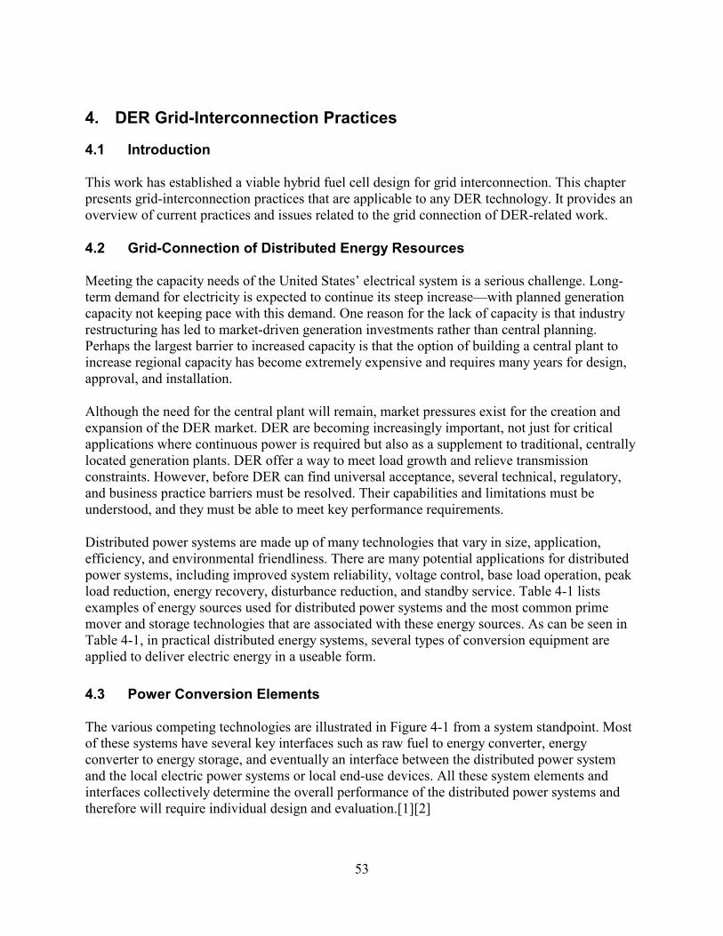
53
4. DER Grid-Interconnection Practices
4.1 Introduction
This work has established a viable hybrid fuel cell design for grid interconnection. This chapter presents grid-interconnection practices that are applicable to any DER technology. It provides an overview of current practices and issues related to the grid connection of DER-related work.
4.2 Grid-Connection of Distributed Energy Resources
Meeting the capacity needs of the United States’ electrical system is a serious challenge. Long-term demand for electricity is expected to continue its steep increase—with planned generation capacity not keeping pace with this demand. One reason for the lack of capacity is that industry restructuring has led to market-driven generation investments rather than central planning. Perhaps the largest barrier to increased capacity is that the option of building a central plant to increase regional capacity has become extremely expensive and requires many years for design, approval, and installation.
Although the need for the central plant will remain, market pressures exist for the creation and expansion of the DER market. DER are becoming increasingly important, not just for critical applications where continuous power is required but also as a supplement to traditional, centrally located generation plants. DER offer a way to meet load growth and relieve transmission constraints. However, before DER can find universal acceptance, several technical, regulatory, and business practice barriers must be resolved. Their capabilities and limitations must be understood, and they must be able to meet key performance requirements.
Distributed power systems are made up of many technologies that vary in size, application, efficiency, and environmental friendliness. There are many potential applications for distributed power systems, including improved system reliability, voltage control, base load operation, peak load reduction, energy recovery, disturbance reduction, and standby service. Table 4-1 lists examples of energy sources used for distributed power systems and the most common prime mover and storage technologies that are associated with these energy sources. As can be seen in Table 4-1, in practical distributed energy systems, several types of conversion equipment are applied to deliver electric energy in a useable form.
4.3 Power Conversion Elements
The various competing technologies are illustrated in Figure 4-1 from a system standpoint. Most of these systems have several key interfaces such as raw fuel to energy converter, energy converter to energy storage, and eventually an interface between the distributed power system and the local electric power systems or local end-use devices. All these system elements and interfaces collectively determine the overall performance of the distributed power systems and therefore will require individual design and evaluation.[1][2]
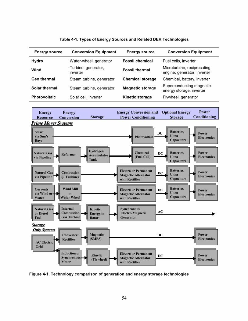
54
Table 4-1. Types of Energy Sources and Related DER Technologies
Energy source Conversion Equipment Energy source Conversion Equipment
Hydro Water-wheel, generator Fossil chemical Fuel cells, inverter
Wind Turbine, generator, inverter Fossil thermal Microturbine, reciprocating
engine, generator, inverter Geo thermal Steam turbine, generator Chemical storage Chemical, battery, inverter
Solar thermal Steam turbine, generator Magnetic storage Superconducting magnetic energy storage, inverter
Photovoltaic Solar cell, inverter Kinetic storage Flywheel, generator
Magnetic(SMES)
HydrogenAccumulatorTank
ReformerNatural Gasvia Pipeline
Chemical(Fuel Cell)
StorageEnergy
Resource Energy
ConversionEnergy Conversion and
Power Conditioning Optional Energy
StoragePower
Conditioning
Batteries,Ultra-Capacitors
Batteries,Ultra-Capacitors
DC
Solar via Sun’s Rays
PhotovoltaicBatteries,Ultra-Capacitors
DC
PowerElectronics
PowerElectronics
PowerElectronics
PowerElectronics
Air PressureVia Winds
Batteries,Ultra-Capacitors
PowerElectronics
Wind Mill or
Water Wheel
KineticKinetic(Flywheel)(Flywheel)
Electro or Permanent Electro or Permanent Magnetic Alternator Magnetic Alternator with Rectifierwith Rectifier
PowerPowerElectronicsElectronics
Natural Gasvia Pipeline
StorageOnly Systems
Prime Mover Systems
Air PressureVia Winds
Air PressureVia Winds
Currentsvia Wind orWater
AC Electric Grid
Induction or Synchronous Motor
Combustion (µ Turbine)
DC
DC
Converter/Rectifier
Electro or Permanent Electro or Permanent Magnetic Alternator Magnetic Alternator with Rectifierwith Rectifier
Electro or Permanent Electro or Permanent Magnetic Alternator Magnetic Alternator with Rectifierwith Rectifier
DC
Natural Gasor Diesel Fuel
Internal Combustion/ Gas Turbine
ACSynchronous Synchronous ElectroElectro--Magnetic Magnetic GeneratorGenerator
Kinetic Kinetic Energy in Energy in RotorRotor
DC
Figure 4-1. Technology comparison of generation and energy storage technologies
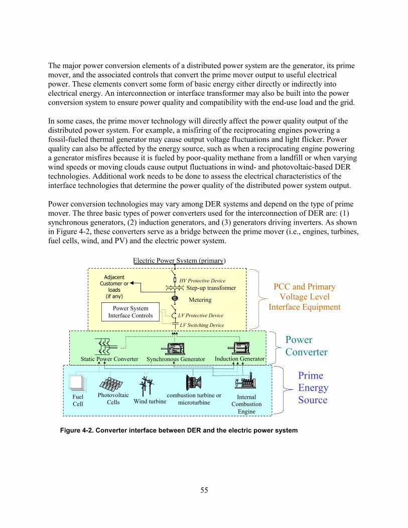
55
The major power conversion elements of a distributed power system are the generator, its prime mover, and the associated controls that convert the prime mover output to useful electrical power. These elements convert some form of basic energy either directly or indirectly into electrical energy. An interconnection or interface transformer may also be built into the power conversion system to ensure power quality and compatibility with the end-use load and the grid.
In some cases, the prime mover technology will directly affect the power quality output of the distributed power system. For example, a misfiring of the reciprocating engines powering a fossil-fueled thermal generator may cause output voltage fluctuations and light flicker. Power quality can also be affected by the energy source, such as when a reciprocating engine powering a generator misfires because it is fueled by poor-quality methane from a landfill or when varying wind speeds or moving clouds cause output fluctuations in wind- and photovoltaic-based DER technologies. Additional work needs to be done to assess the electrical characteristics of the interface technologies that determine the power quality of the distributed power system output.
Power conversion technologies may vary among DER systems and depend on the type of prime mover. The three basic types of power converters used for the interconnection of DER are: (1) synchronous generators, (2) induction generators, and (3) generators driving inverters. As shown in Figure 4-2, these converters serve as a bridge between the prime mover (i.e., engines, turbines, fuel cells, wind, and PV) and the electric power system.
Electric Power System (primary)
Wind turbine
Photovoltaic Cells
Fuel Cell
Internal Combustion
Engine
combustion turbine or microturbine
Static Power Converter Synchronous Generator Induction Generator
Step-up transformer
Metering Power System
Interface Controls
Prime Energy Source
Power Converter
PCC and Primary Voltage Level
Interface Equipment
Adjacent Customer or
loads (if any)
HV Protective Device
LV Protective Device
LV Switching Device
Figure 4-2. Converter interface between DER and the electric power system
56
4.3.1 Rotating Power Converters 4.3.1.1 Synchronous Generators
An electromagnet (wound-rotor) or permanent magnet in the rotor produces the magnetic field in a synchronous generator. Consequently, the frequency of the AC electric power produced (60 Hz, for example) is exactly related to the rotational speed and number of poles of the generator rotor (1,800 rpm and four poles, for example). Similarly, the magnitude of the voltage produced (and the reactive power delivered to the power system or consumed by the generator) is directly related to the strength of the magnetic field in the rotor. All large synchronous machines have wound rotors and excitation systems to allow for magnetic field control.
The stator of the synchronous generator contains three-phase armature windings, and the rotor carries a direct current field winding. Two distinct types of rotors are employed in synchronous generators. These are the salient-pole rotor and the round or cylindrical rotor. In the round rotor design, the field windings are located in slots cut axially along the rotor length. The rotor diameter is relatively small, and the machine is suitable for operation at the high speeds typical of steam or gas turbines. In salient pole rotors, distinct pole-piece structures project radically around the rotor. Rotor diameters are correspondingly larger, so they are most commonly used in relatively low-speed applications, such as with hydraulic turbines or water wheels.
4.3.1.2 Induction Generators
An induction generator is essentially an induction motor that is being driven above its synchronous or zero-slip speed by the prime mover. The stator of an induction generator is similar to that of a synchronous machine. It is wound for three-phase operation and for a specific number of poles depending on the desired speed of operation. The rotor is normally of a squirrel cage design consisting of heavy conductor bars running parallel to the shaft and connected at their ends by conducting rings concentric with the shaft.
An induction generator differs from a synchronous generator in that the induction type relies on the power system to induce the required magnetic field in the rotor. This field is induced based on the relative difference in speed between the machine rotor and the power system frequency. This difference is also called “slip.” Slip increases with machine loading. As a generator, the induction machine rotor is driven faster, and as a motor, the rotor is slower than the synchronous speed for the machine and power system (900 rpm if six-pole, 1,800 rpm if four-pole, and 3,600 rpm if two-pole at 60 Hz).
As a consequence, the induction generator mechanical speed cannot operate in synchronism with the power system frequency because there is no field induced when the rotor speed is the same as the synchronous speed. To generate electricity, the machine must run faster than synchronous speed. For example, a four-pole machine in a 60-Hz power system generates at speeds of 1,820–1,860 rpm, whereas 1,800 rpm is synchronous speed. Wind and micro-hydro facilities typically use induction generators because uncoupling the electrical and mechanical speeds enhances power transfer.

57
Because the induction generator consumes rather than generates reactive power, it cannot control its output voltage. Consequently, induction generators are not good at supplying isolated loads. Even so, there is no guarantee that an induction generator will not support an isolated system or “unintended island.” If there is just the right amount of capacitance and real load in the island, the induction machine can generate electricity. Induction generators have lower surge current capacity than synchronous generators, so their ability to support a momentary overload is reduced. The generator output drops rapidly as voltage collapses, so induction generators have relatively low fault contribution, and they are not a source of voltage harmonics.
4.3.2 Inverters
Despite the fact that the inverter generally reduces the cost of interconnection, there are several other cost issues related to inverters. The added value of the inverter in making the interconnection is not easily defined because of inconsistencies in interconnection functions that are provided by the inverter and functions requiring additional equipment.
One reason for this is that inverter capabilities, such as providing specific relay protections and controls or DER system isolation, are not always accepted by the electric service provider responsible for the interconnection. As shown in Figure 4-3, from an EEI Interconnection study [5], the recommended practice for interconnection of small inverters includes a significant number of additional relaying functions. This added cost of interconnection is expected to remain an issue for the future deployment of small DER systems.
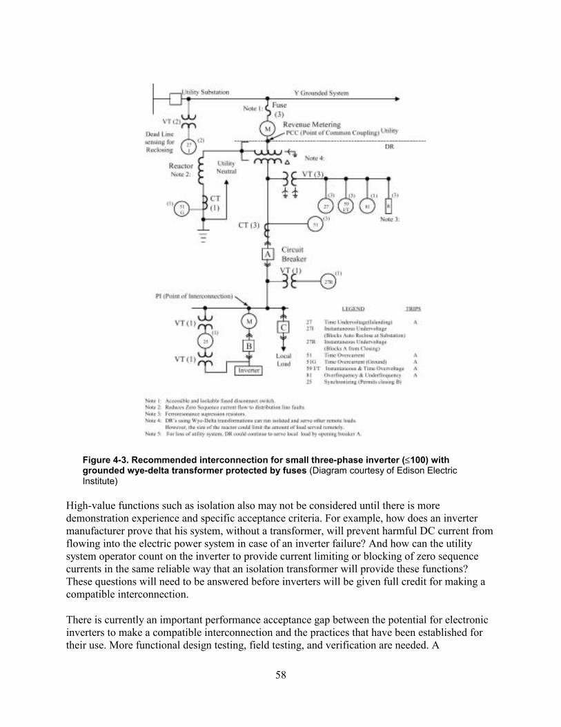
58
Figure 4-3. Recommended interconnection for small three-phase inverter (≤100) with grounded wye-delta transformer protected by fuses (Diagram courtesy of Edison Electric Institute)
High-value functions such as isolation also may not be considered until there is more demonstration experience and specific acceptance criteria. For example, how does an inverter manufacturer prove that his system, without a transformer, will prevent harmful DC current from flowing into the electric power system in case of an inverter failure? And how can the utility system operator count on the inverter to provide current limiting or blocking of zero sequence currents in the same reliable way that an isolation transformer will provide these functions? These questions will need to be answered before inverters will be given full credit for making a compatible interconnection.
There is currently an important performance acceptance gap between the potential for electronic inverters to make a compatible interconnection and the practices that have been established for their use. More functional design testing, field testing, and verification are needed. A
59
communication interface that will allow system operators to monitor and control inverter-connected DER systems will also increase the utilization and add value to available inverter capabilities.
4.3.2.1 Static Power Converters
Static power converters are used to convert the output power of DC energy sources such as batteries, photovoltaic cells, and fuel cells into suitable utilization current, voltage, and frequency for use by utility loads. They may also be employed to adjust, convert, or stabilize variable frequency AC sources. For example, static power converters may be used with wind turbine generators to obtain stable, clean power frequency or with very high-frequency AC sources such as microturbine generators to obtain suitable power frequency. The term “static” in static power converter refers to the non-moving solid-state parts that perform the key power conversion functions.
4.3.2.2 Line-Commutated Inverters
A line-commutated inverter uses a bridge configuration to invert DC power. Semiconductor devices are typically turned on by a signal from the inverter control. However, these devices rely on the power system voltage to force the output current through zero and to turn off the switch, hence the term “line-commutated.” As a consequence, the inverter frequency follows the line frequency, and it is usually not practical to provide voltage regulation. Line-commutated inverters also consume reactive power and are not suitable to power-isolated loads. Even so, the line-commutated characteristics cannot be relied on to guarantee a shutdown when in an islanded load situation. Tests have shown that with the right amount of capacitance and real load, the line-commutated inverter can continue to energize an islanded system.
As with other inverters, overload capability is limited. Line commutation does not allow for direct wave shaping by modulating switching frequency. Therefore, harmonic distortions will be higher than in the self-commutated inverter (in the range of 10–50%) unless filters or transformers are added to trap and cancel harmonics. Also, the line-commutated inverter may operate in a mode in which current is discontinuous, creating both high- and low-frequency harmonics.
4.3.2.3 Self-Commutated Inverters
A self-commutated inverter is able to invert by commutating switches on and off to reverse current in both directions. With on/off switching control, a self-commutating inverter can control frequency. Many self-commutated designs are also able to regulate and shape the output current using switching techniques such as pulse-width modulation. In this regard, the self-commutated inverters act like a synchronous generator and are able to supply real and reactive power suitable for powering isolated or interconnected loads.
Most inverters have a relatively low overload capability, typically limited to two to three times normal rated output. Switching to produce AC from DC will create distortions in the output
60
voltage and current waveforms. The waveforms and the frequency of the harmonics that compose the distortions depend on the switching frequency, output filtering, and inverter technology. Typically, these inverters are designed to maintain unity power factor and harmonic distortions of 5–10%.
Most self-commutated inverters available at the time of this writing are high-frequency switching designs. (The term “high-frequency” is used loosely to mean the modulation frequencies are significantly above utility line-frequency, ranging from about 1 kHz to tens of kilohertz, making response times of a fraction of a 60-Hz cycle possible.) These high-frequency controlled inverters are the result of a natural evolution in design to allow minimizing of harmonic current output, control of power factor, and a myriad of other operational features that are most readily addressed with digital technology and the rapid response possible with high frequency switching.
4.3.2.4 Non-Islanding Inverters
Non-islanding inverters are designed for connection as parallel sources to the utility service. In addition to fixed over- and under-frequency and over- and under-voltage trips for anti-islanding protection, this type of inverter includes a means to ensure unstable operation leading to shutdown when the utility source is not present.
A non-islanding inverter will cease to energize the utility line in 10 or fewer cycles when subjected to a typical islanded load in which either of the following is true:
• There is at least a 50% mismatch in real power load to inverter output (i.e., real power load is less than 50% or greater than 150% of inverter power output)
• The islanded-load power factor is less than 0.95 (lead or lag).
If the real power generation to load match is within 50% and the islanded-load power factor is greater than 0.95, then a non-islanding inverter will cease to energize the utility line within 2 s instead of the 10 cycles whenever the connected line has a quality factor of 2.5 or less.
4.4 Relay Protection 4.4.1 Passive Protection
The most common means to prevent islanding is to use voltage and frequency relays on the DER unit that are set to trip when either of these two values migrates outside selected limits. This form of islanding protection is known as passive protection. It prevents islanding in most cases because when a section of the distribution system containing the DER unit separates from the grid, the output of the DER unit will generally not match the power demand within the separated area. For synchronous or induction generators, this results in a change in voltage and frequency, causing the relays to trip in a very short time. Typically, the relays would be set to a rather tight frequency range of perhaps +1 Hz or even +0.5 Hz. Voltage would be a bit wider to allow for typical voltage-regulation excursions on the feeder (+5–10% would be typical).
61
Self-commutated inverters that transition to a voltage-source mode during system separation are not likely to significantly change their operating frequency during such islanding events because they are not subjected to the inertial limitations of rotational generators. As a result, for these types of inverters, it is the voltage relay that is the most important line of defense against islanding.
4.4.2 Active Protection
The PV industry is very concerned about islanding issues and is probably further along than any other distributed generation industry at promoting the development of anti-islanding protection circuitry technologies for inverters. A number of techniques are being developed that go beyond standard voltage and frequency relays. IEEE 929 and UL 1741 [3] discuss in detail the techniques and issues regarding islanding. A test is also being developed by UL to test inverters to meet a UL anti-islanding certification. The algorithms go beyond standard passive techniques involving voltage and frequency relays. The methods utilized involve active techniques, causing the frequency of the inverter to quickly drift out of specification as soon as the utility signal disappears. This, in turn, causes the frequency relay to trip the unit. Depending on how well the load is balanced to the inverter output at the moment of utility separation, this process can require up to 10 seconds, as specified by IEEE 929.
4.5 Interconnection Transformer
The interconnection transformer is often a point of controversy between utilities and DER equipment manufacturers. Most utilities consider the transformer an integral part of the power conversion system. In contrast, most DER equipment manufacturers would rather avoid the additional transformer because of the cost, bulk, system losses, and potential installation delays while waiting on transformer delivery. The need for this transformer depends on the utility system, the local grounding (compared with distribution feeder grounding), and the type of DER being installed. Inverters tend to be easier to connect without isolation than are synchronous machines. As seen in Figure 4-4, there are at least three connection scenarios that provide transformer isolation.
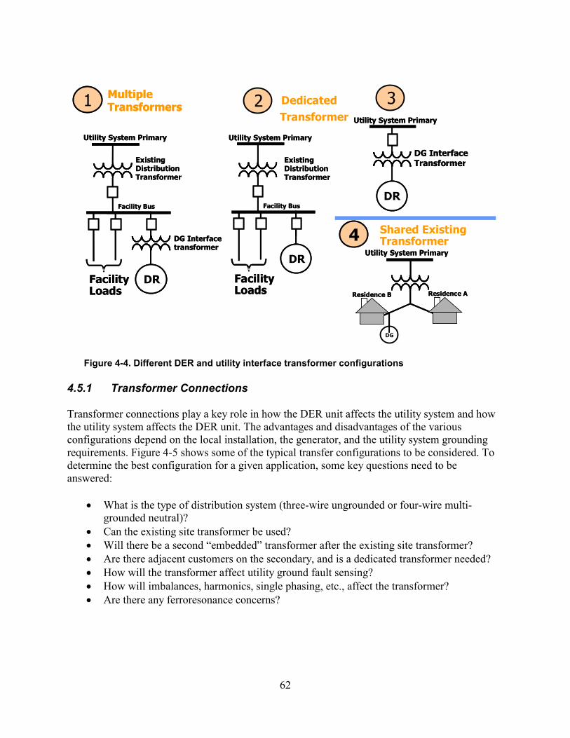
62
DG Interface transformer
DG
Existing Distribution Transformer
Facility Bus
Utility System Primary
Facility Loads
DG Interface Transformer
DG
Utility System Primary
DG
Existing Distribution Transformer
Facility Bus
Utility System Primary
Facility Loads
1
4
Multiple Transformers
Residence B
Utility System Primary
Residence A
DG
Shared Existing Transformer DG Interface
transformer
DG DR
Existing Distribution Transformer
Facility Bus
Utility System Primary
Facility Loads
DG Interface Transformer
DG DR
Utility System Primary
DGDR
Existing Distribution Transformer
Facility Bus
Utility System Primary
Facility Loads
1 2 3
4
Multiple Transformers Dedicated
Transformer
Residence B
Utility System Primary
Residence A
Figure 4-4. Different DER and utility interface transformer configurations
4.5.1 Transformer Connections
Transformer connections play a key role in how the DER unit affects the utility system and how the utility system affects the DER unit. The advantages and disadvantages of the various configurations depend on the local installation, the generator, and the utility system grounding requirements. Figure 4-5 shows some of the typical transfer configurations to be considered. To determine the best configuration for a given application, some key questions need to be answered:
• What is the type of distribution system (three-wire ungrounded or four-wire multi-grounded neutral)?
• Can the existing site transformer be used? • Will there be a second “embedded” transformer after the existing site transformer? • Are there adjacent customers on the secondary, and is a dedicated transformer needed? • How will the transformer affect utility ground fault sensing? • How will imbalances, harmonics, single phasing, etc., affect the transformer? • Are there any ferroresonance concerns?
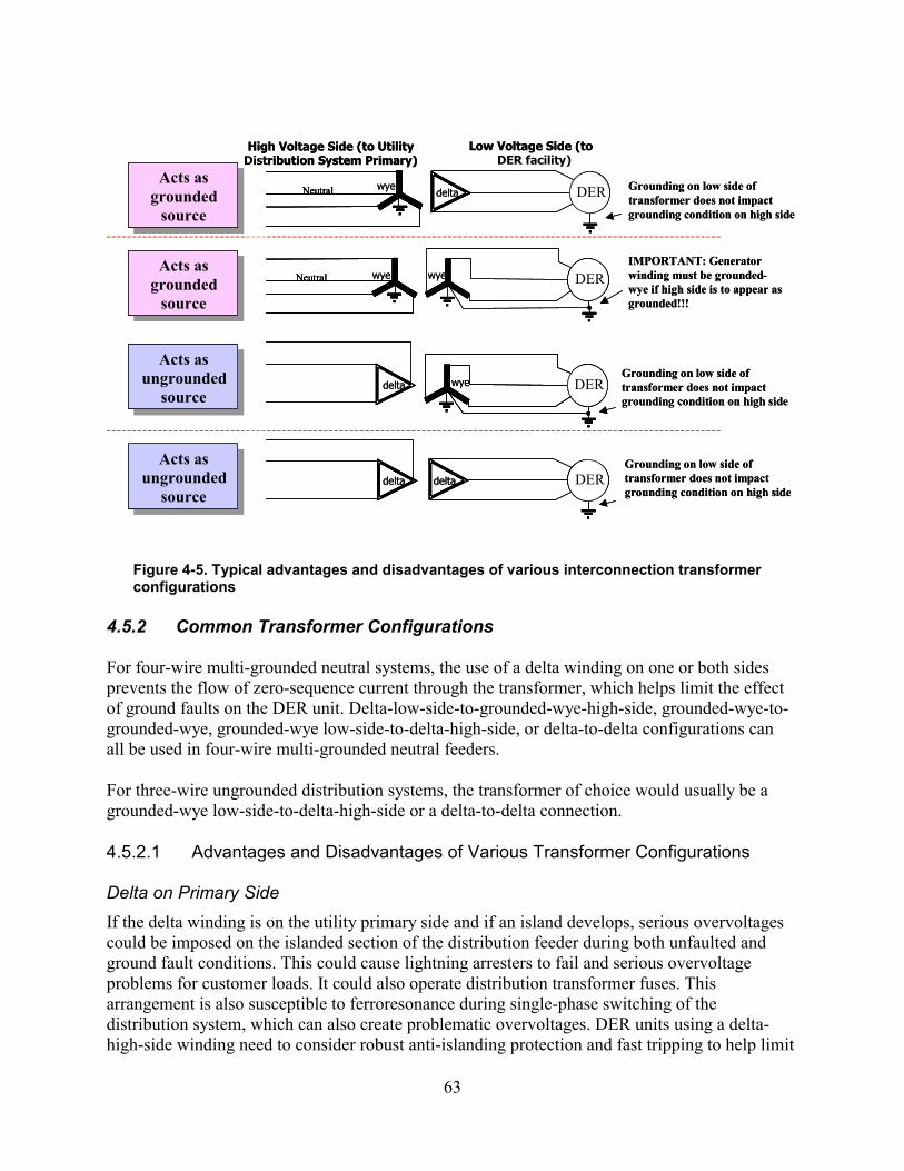
63
delta DGNeutral
Neutral
Low Voltage Side (to DER facility)
High Voltage Side (to Utility Distribution System Primary)
DG
DG
DG
delta
delta delta
wye
wye wye
wye
Acts as grounded
source
Acts as grounded
source
Acts as grounded
source
Acts as grounded
source
Acts as ungrounded
source
Acts as ungrounded
source
Acts as ungrounded
source
Acts as ungrounded
source
Grounding on low side of transformer does not impact grounding condition on high side
Grounding on low side of transformer does not impact grounding condition on high side
Grounding on low side of transformer does not impact grounding condition on high side
IMPORTANT: Generator winding must be grounded-wye if high side is to appear as grounded!!!
delta DGDERNeutral Neutral
Neutral Neutral
Low Voltage Side (to High Voltage Side (to Utility Distribution System Primary)
DGDER
DGDGDER
DGDER
delta
delta delta
wye
wye wye
wye
Acts as grounded
source
Acts as grounded
source
Acts as grounded
source
Acts as grounded
source
Acts as ungrounded
source
Acts as ungrounded
source
Acts as ungrounded
source
Acts as ungrounded
source
Grounding on low side of transformer does not impact grounding condition on high side
Grounding on low side of transformer does not impact grounding condition on high side
Grounding on low side of transformer does not impact grounding condition on high side
IMPORTANT: Generator winding must be grounded-wye if high side is to appear as grounded!!!
Figure 4-5. Typical advantages and disadvantages of various interconnection transformer configurations
4.5.2 Common Transformer Configurations
For four-wire multi-grounded neutral systems, the use of a delta winding on one or both sides prevents the flow of zero-sequence current through the transformer, which helps limit the effect of ground faults on the DER unit. Delta-low-side-to-grounded-wye-high-side, grounded-wye-to-grounded-wye, grounded-wye low-side-to-delta-high-side, or delta-to-delta configurations can all be used in four-wire multi-grounded neutral feeders.
For three-wire ungrounded distribution systems, the transformer of choice would usually be a grounded-wye low-side-to-delta-high-side or a delta-to-delta connection.
4.5.2.1 Advantages and Disadvantages of Various Transformer Configurations
Delta on Primary Side If the delta winding is on the utility primary side and if an island develops, serious overvoltages could be imposed on the islanded section of the distribution feeder during both unfaulted and ground fault conditions. This could cause lightning arresters to fail and serious overvoltage problems for customer loads. It could also operate distribution transformer fuses. This arrangement is also susceptible to ferroresonance during single-phase switching of the distribution system, which can also create problematic overvoltages. DER units using a delta-high-side winding need to consider robust anti-islanding protection and fast tripping to help limit
64
the duration of overvoltage problems if they should develop. The impact of the temporary overvoltage on the primary system lightning arresters and customer loads needs to be carefully scrutinized in such situations to make sure the protection can clear the DER unit before the arresters and loads are damaged.
It is important to note that many newer three-phase commercial buildings are served by grounded-wye-to-delta transformers (delta on the high side). These are the types of installations for which many DER units are being considered, so care should always be exercised to determine the transformer winding type when attempting to use an existing building transformer for the DER interconnection. In practice, the DER unit would need to be relatively large to island in a manner in which it could create high voltages on the primary side of a four-wire system, so the delta winding concern would not usually apply to smaller units (less than 100 kVA). For large DER units applied on four-wire multi-grounded systems, a grounded-wye winding on the high side with a suitable grounding impedance and a delta winding on the DER unit side is probably the best technical solution.
Multi-grounded Neutral Systems For multi-grounded neutral systems, the use of a grounded-wye winding on the high side and delta on the low side will limit the overvoltages that can develop during a DER unit island condition, thereby sparing lightning arresters and feeder loads from damage. However, this arrangement acts as a ground source, and zero-sequence current from the high side will circulate in the delta winding on the low side, possibly causing heating problems within the transformer. A commonly practiced solution to this problem is to place grounding impedance in the high-side neutral connection to limit the flow of excessive circulating currents. The ground impedance should be high enough to limit the circulating current but low enough to maintain effective grounding of the DER unit.[4]
Many protection engineers object to the placement of multiple grounding sources along the multi-grounded neutral feeder because they can cause coordination problems for upstream feeder equipment during ground faults. This is because some of the unbalanced ground-fault currents disappear into the ground source transformer banks, never reaching upstream devices such as substation ground fault relays. In situations in which there are many low-impedance grounding sources on the multi-grounded neutral feeder, ground-fault relaying on the feeder can be severely desensitized.
Grounded-Wye A grounded-wye transformer winding may be substituted for the low-side delta winding as long as the generator applied to it meets effective grounding requirements. If the generator neutral connection does not meet effective grounding requirements or is not grounded at all, then the transformer bank does not create an effectively grounded source with respect to the DER unit, even though the neutral connections to the transformer are grounded on both sides. Under this condition, a sufficiently large DER unit could then impose high voltages on the utility system when an island occurs.

65
Some inverters need isolation from ground and are not designed to operate with a grounded-wye winding on the inverter side of the transformer. Consequently, this may dictate the use of a delta winding on the DER side of the system to keep the inverter output from being grounded.
Field experience has suggested that some static power converters are failing and/or tripping because of the inability of their power electronics to handle common temporary overvoltages that occur on the utility system because of line-to-ground faults. A wye-wye connection will pass these overvoltages directly from the utility to the DER unit. If there is a concern that a particular inverter is sensitive to these types of overvoltages, then a prudent choice of transformer would be a grounded-wye high-side-to-delta-low-side or a delta-to-delta. These transformer arrangements should mitigate line-to-ground fault-related voltage swells of utility origin from reaching the DER unit. However, delta-to-delta will not maintain effective grounding and should be avoided for multi-grounded neutral feeders if the DER unit is large. The grounded-wye-to-delta would be the better choice for larger installations.
4.5.3 Interconnection Support Equipment
Support-equipment manufacturers will play an important roll in providing needed products for DER interconnections. This group might be equated with the manufacturers that provide the many peripherals and accessories to the PC market. Many are new players providing solutions to problems that didn’t exist until DER systems evolved into new applications. The most common support equipment offered from these manufacturers is the transfer switch. Many offer basic components for fault interruption, sensing, connecting hardware, and surge protection. Most offer a communication port for connection with other DER equipment.
Probably the most needed support equipment, from a cost of interconnection viewpoint, is not readily available. The first and foremost need is for prepackaged paralleling and synchronization control equipment for small systems. This equipment is designed and packaged for larger systems. A typical low-voltage paralleling switchgear at 480 V is in the 400-4,000 A range. Below that range, the cost per kilovolt-ampere increases significantly. We are not aware of any that are available at low voltage and 200 amps or below.
The other much-needed support system is one that will provide a communication link with the system operator or dispatcher. The unavailability of this requirement is sometimes misunderstood because many DER support-equipment vendors and DER system manufacturers offer built-in or optional communication ports. However, these capabilities are limited to local systems that use and incorporate the same media and, more importantly, the same communication protocols and control software.
To communicate with the utility system operator today requires that the system operator and all the DER users acquire the same communication and control system. This is not a likely scenario given all the DER system types, user preferences, and communications system manufacturers. Because DER is a relatively new technology, it is expected that the number and types of support equipment available will grow as new applications evolve. In the meantime, the need for common communication links will increase. Implementing new standards and creating some

66
universal communication format, such as HTML for the Internet, is likely the answer to the DER communication issue.
Most DER system developers are beginning to address interconnection details or are becoming more willing to share their results and conclusions. From our ongoing discussions with DER manufacturers, most indicate that they plan to provide interconnection hardware in their system packages. Of course, depending on the installation, functions such as the interrupting device or circuit breaker may necessarily be external to the DER system. Even so, functions such as controlled connection and disconnection can be integrated into the DER system. DER systems that use inverters may offer all the interconnection functions built-in.
67
5. References
1. EPRI. TAG Technical Assessment Guide: Volume 5: Distributed Resources. TR-113165-V5. Palo Alto, CA: Electric Power Research Institute, November 1999.
2. EPRI. Guide for Performance Characterization of Emerging Distributed Resource Technologies. TP-1003970. Palo Alto, CA: Electric Power Research Institute, 2001.
3. Standard for Static Inverters and Charge Controllers for Use in Photovoltaic Power Systems. UL 1741. Underwriters Laboratories Inc.
4. IEEE Guide for Surge Voltages in Low-Voltage AC Power Circuits. IEEE/ANSI C62.41. Piscataway, NY: IEEE Standards Association, 2000.
5. Interconnection Working Group; Murry Davis, Chair. Edison Electric Institute Distributed Energy Resources Task Force Interconnection Study. June 2000.
6. Larminie, J.; Dicks, A. Fuel Cell Systems Explained. John Wiley & Sons, pp. 17.
68
6. Related Reading
1. Gilchrist, T. “Fuel Cells to the Fore.” Spectrum Magazine; November 1998; pp. 35–40.
2. Wolk, R. “Fuel Cells for Homes and Hospitals.” Spectrum Magazine; May 1999; pp. 45–52.
3. Douglas, J. “Solid Futures in Fuel Cells.” EPRI Journal; March 1994; pp. 7–13.
4. Wilson, M.; Valerio, J.; Gottesfeld, S. “Low Platinum Loading Electrodes for Polymer Electrolyte Fuel Cells Fabricated Using Thermoplastic Ionomers.” Electrochimica Acta; Vol. 40 No. 3, 1995; pp.355–363.
5. Varakin, I.N.; Klementov, A.D.; Litvinenko, S.V.; Starodubtsev; N.F., Stepanov, A.B. “Application of Ultracapacitors as Traction Energy Sources.” The 7th International Seminar on Double Layer Capacitors and Similar Energy Storage Devices. Deerfield Beach, FL: December 1997.
6. Miller, J.R. “Pulse Power Performance of Electrochemical Capacitors: Technical Status of Present Commercial Devices.” The 8th International Seminar on Double Layer Capacitors and Similar Energy Storage Devices. Deerfield Beach, FL: December 1998.
7. Beliakov, A.I.; Brintsev, A.M. “Development and Application of Combined Capacitors: Double Electric Layer – Pseudocapacity.” The 7th International Seminar on Double Layer Capacitors and Similar Energy Storage Devices. Deerfield Beach, FL: December 1997.
8. Geist, T. Electrochemical Capacitors: Performance and Opportunities for Power Quality Applications. 1000089. Palo Alto, CA: Electric Power Research Institute, 2000.
9. Mohan, N. “Power Electronics: Converters, Applications, and Design.” John Wiley & Sons, 1995; pp. 188–189.
10. Varakin, I.N.; Klementov, A.D.; Litvinenko, S.V.; Starodubtsev, N.F.; Stephanov, A.B. “New Ultracapacitors Developed by JSC ESMA for Various Applications.” The 8th International Seminar on Double Layer Capacitors and Similar Energy Storage Devices. Deerfield Beach, FL: December 1998.
11. Hoffman, D.P.; Smith, R.E. “Ultracapacitors for the Power Quality Market,” Powersystems World ’97 Conference, September 1997, Baltimore, MD.
12. Spyker, R.L.; Nelms, R.M. “Evaluation of Double Layer Capacitor Technologies for High Power and High Energy Storage Applications.” Proceedings of IECON '97. 0-7803-3932-0. November 1997.
13. McGough, M.; Coulter, B. “Ultracapacitors for Power Conversion.”

69
14. Miller, J.R.; Conway, B.E. “Fundamentals and Applications of Electrochemical Capacitors.” An electrochemical short course, May 1997.
15. IEEE. Guide for the Application of Metal-Oxide-Arresters for Alternating-Current Systems. IEEE/ANSI C62.22. Piscataway, NY: IEEE Standards Association,1997.
16. NFPA. National Electrical Code® (NEC®). 70-1999.
17. “PEM Fuel Cells for Commercial Buildings.” Office of Building Technology, State and Community Programs, PNNL-12051. U.S. Department of Energy, Washington, D.C.
18. “Engineering Guide for Integration of Distributed Generation and Storage Into Power Distribution Systems.” TR1000419. Palo Alto, CA.: Electric Power Research Institute, 2000.
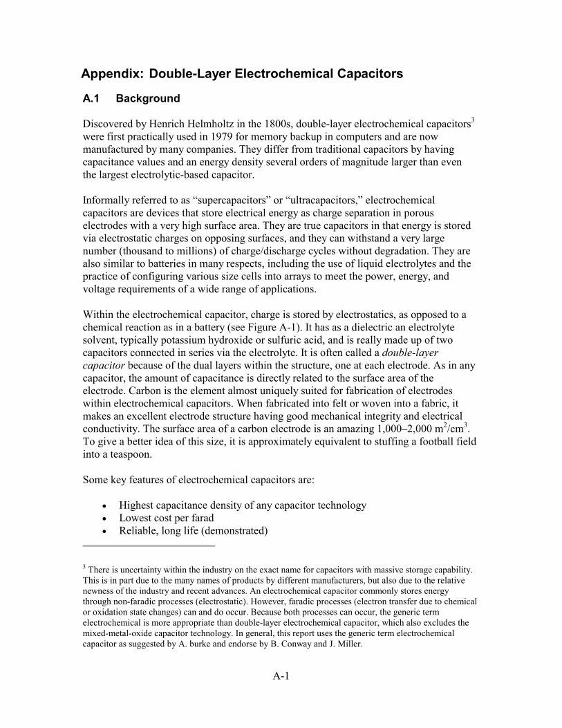
A-1
Appendix: Double-Layer Electrochemical Capacitors
A.1 Background
Discovered by Henrich Helmholtz in the 1800s, double-layer electrochemical capacitors3 were first practically used in 1979 for memory backup in computers and are now manufactured by many companies. They differ from traditional capacitors by having capacitance values and an energy density several orders of magnitude larger than even the largest electrolytic-based capacitor.
Informally referred to as “supercapacitors” or “ultracapacitors,” electrochemical capacitors are devices that store electrical energy as charge separation in porous electrodes with a very high surface area. They are true capacitors in that energy is stored via electrostatic charges on opposing surfaces, and they can withstand a very large number (thousand to millions) of charge/discharge cycles without degradation. They are also similar to batteries in many respects, including the use of liquid electrolytes and the practice of configuring various size cells into arrays to meet the power, energy, and voltage requirements of a wide range of applications.
Within the electrochemical capacitor, charge is stored by electrostatics, as opposed to a chemical reaction as in a battery (see Figure A-1). It has as a dielectric an electrolyte solvent, typically potassium hydroxide or sulfuric acid, and is really made up of two capacitors connected in series via the electrolyte. It is often called a double-layer capacitor because of the dual layers within the structure, one at each electrode. As in any capacitor, the amount of capacitance is directly related to the surface area of the electrode. Carbon is the element almost uniquely suited for fabrication of electrodes within electrochemical capacitors. When fabricated into felt or woven into a fabric, it makes an excellent electrode structure having good mechanical integrity and electrical conductivity. The surface area of a carbon electrode is an amazing 1,000–2,000 m2/cm3. To give a better idea of this size, it is approximately equivalent to stuffing a football field into a teaspoon.
Some key features of electrochemical capacitors are:
• Highest capacitance density of any capacitor technology • Lowest cost per farad • Reliable, long life (demonstrated)
3 There is uncertainty within the industry on the exact name for capacitors with massive storage capability. This is in part due to the many names of products by different manufacturers, but also due to the relative newness of the industry and recent advances. An electrochemical capacitor commonly stores energy through non-faradic processes (electrostatic). However, faradic processes (electron transfer due to chemical or oxidation state changes) can and do occur. Because both processes can occur, the generic term electrochemical is more appropriate than double-layer electrochemical capacitor, which also excludes the mixed-metal-oxide capacitor technology. In general, this report uses the generic term electrochemical capacitor as suggested by A. burke and endorse by B. Conway and J. Miller.
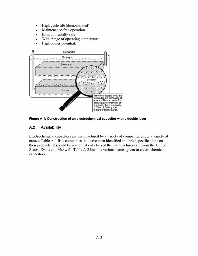
A-2
• High cycle life (demonstrated) • Maintenance-free operation • Environmentally safe • Wide range of operating temperature • High power potential.
Figure A-1: Construction of an electrochemical capacitor with a double layer
A.2 Availability
Electrochemical capacitors are manufactured by a variety of companies under a variety of names. Table A-1 lists companies that have been identified and brief specifications on their products. It should be noted that only two of the manufacturers are from the United States: Evans and Maxwell. Table A-2 lists the various names given to electrochemical capacitors.
A-3
Table A-1: Listing of Manufacturers of Double-Layer Electrochemical Capacitors
Company Capacitance (F) Voltage (V) Energy (kJ) Asahi Glass 240 2.5 1 Asahi Glass 4,300 2.5 13 PCOND 85 28 34 PCOND 25 64 51 ELIT 50 31 24 ELIT 0.5 450 50 ELIT 0.5 359 30 ESMA 130,000 1.3 166 ESMA 32,000 1.4 41 ESMA 3,200 1.4 3 Evans 0.56 10 2.8 Evans 0.033 25 0.01 Isuzu/Fuji 100 14 10 Maxwell 2,700 2.3 7 Matsushita 470 2.3 1 NEC 500 5.5 7 NEC 470 15 53
Table A-2. Product Names for Electrochemical Capacitors
Aerocap Hypercap Batcap Maxcap Capattery Pscap Dynacap Supercap Goldcap Ultracap
A.3 Comparison with Other Similar Storage Technologies
As shown in Table A-3, electrochemical capacitors fit between traditional capacitors and batteries in terms of time constant, energy density, and power density. Although it is true that a battery has the largest energy density—meaning more energy is stored per weight than other technologies—it is important to consider the availability of that energy. For example, how fast can it be used? This is the traditional advantage of capacitors. With a time constant of less than 0.1 second, energy can be taken from a capacitor at a very high rate. Conversely, the same size battery will not be able to supply the necessary energy in the same time period. Electrochemical capacitors fit between the two, with a time constant range of 0.2 to 10 seconds.
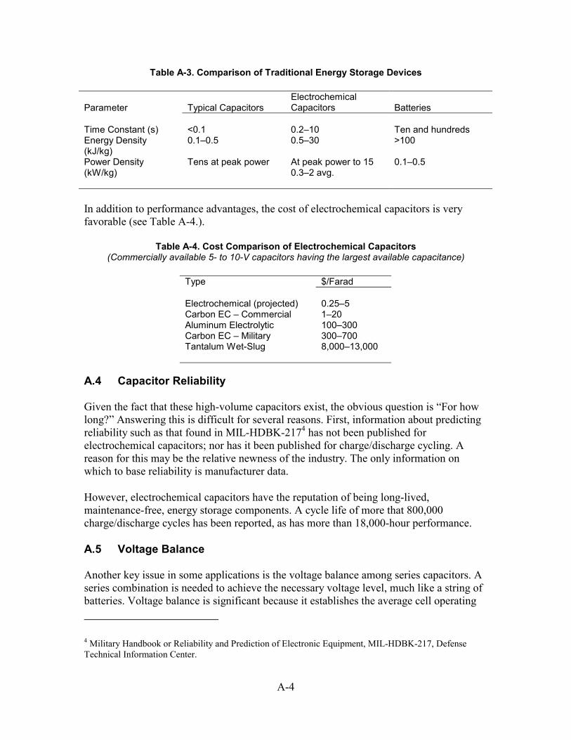
A-4
Table A-3. Comparison of Traditional Energy Storage Devices
Parameter Typical Capacitors Electrochemical Capacitors Batteries
Time Constant (s) <0.1 0.2–10 Ten and hundreds Energy Density (kJ/kg)
0.1–0.5 0.5–30 >100
Power Density (kW/kg)
Tens at peak power At peak power to 15 0.3–2 avg.
0.1–0.5
In addition to performance advantages, the cost of electrochemical capacitors is very favorable (see Table A-4.).
Table A-4. Cost Comparison of Electrochemical Capacitors (Commercially available 5- to 10-V capacitors having the largest available capacitance)
Type $/Farad Electrochemical (projected) 0.25–5 Carbon EC – Commercial 1–20 Aluminum Electrolytic 100–300 Carbon EC – Military 300–700 Tantalum Wet-Slug 8,000–13,000
A.4 Capacitor Reliability
Given the fact that these high-volume capacitors exist, the obvious question is “For how long?” Answering this is difficult for several reasons. First, information about predicting reliability such as that found in MIL-HDBK-2174 has not been published for electrochemical capacitors; nor has it been published for charge/discharge cycling. A reason for this may be the relative newness of the industry. The only information on which to base reliability is manufacturer data.
However, electrochemical capacitors have the reputation of being long-lived, maintenance-free, energy storage components. A cycle life of more that 800,000 charge/discharge cycles has been reported, as has more than 18,000-hour performance.
A.5 Voltage Balance
Another key issue in some applications is the voltage balance among series capacitors. A series combination is needed to achieve the necessary voltage level, much like a string of batteries. Voltage balance is significant because it establishes the average cell operating
4 Military Handbook or Reliability and Prediction of Electronic Equipment, MIL-HDBK-217, Defense Technical Information Center.
A-5
voltage, determines effective energy density, affects power performance, and sets manufacturing yield for a given cell-voltage, capacitor-voltage, and cell-uniformity tolerance.
Operating a multi-cell capacitor at the maximum possible unit-cell voltage offers advantages such as:
• Higher energy density because the capacitance is larger at a given voltage • Better power performance because fewer cells means lower ESR • Greater reliability because of fewer components • Lower cost because there are fewer cells.
Manufacturers have developed two methods to deal with voltage balance. The first is an external solution that requires the use of series resistors in parallel with the capacitors. The disadvantage of this method is the high leakage current, not because of the capacitance but through the resistors.
The second method is an internal, second-order effect currently only inherent in the ESMA design. Termed pseudocapacitance, the physics of the phenomenon is beyond the scope of this document. However, it is analogous to equalizing a battery. The net effect is that voltage balance in the ESMA capacitors is not an issue. A positive side effect is that the leakage current is very low, which allows for excellent shelf life.
A.6 Status of Large (>1 kJ) Capacitor Development
A few of the growing electrochemical capacitor markets are:
• Wireless communication • Automotive
o Electric vehicle o Gas/electric hybrid o Catalytic preheat o Starting, lighting ignition o System power (steering, air conditioning)
• Off-road transportation o Lift trucks o Fixed-duty cycle buses
• UPSs • ASDs • Military systems • Consumer applications (memory backup for personal computers).
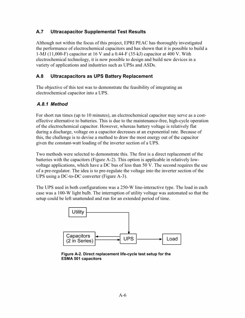
A-6
A.7 Ultracapacitor Supplemental Test Results
Although not within the focus of this project, EPRI PEAC has thoroughly investigated the performance of electrochemical capacitors and has shown that it is possible to build a 1-MJ (11,000-F) capacitor at 16 V and a 0.44-F (35-kJ) capacitor at 400 V. With electrochemical technology, it is now possible to design and build new devices in a variety of applications and industries such as UPSs and ASDs.
A.8 Ultracapacitors as UPS Battery Replacement
The objective of this test was to demonstrate the feasibility of integrating an electrochemical capacitor into a UPS.
A.8.1 Method
For short run times (up to 10 minutes), an electrochemical capacitor may serve as a cost-effective alternative to batteries. This is due to the maintenance-free, high-cycle operation of the electrochemical capacitor. However, whereas battery voltage is relatively flat during a discharge, voltage on a capacitor decreases at an exponential rate. Because of this, the challenge is to devise a method to draw the most energy out of the capacitor given the constant-watt loading of the inverter section of a UPS.
Two methods were selected to demonstrate this. The first is a direct replacement of the batteries with the capacitors (Figure A-2). This option is applicable in relatively low-voltage applications, which have a DC bus of less than 50 V. The second requires the use of a pre-regulator. The idea is to pre-regulate the voltage into the inverter section of the UPS using a DC-to-DC converter (Figure A-3).
The UPS used in both configurations was a 250-W line-interactive type. The load in each case was a 100-W light bulb. The interruption of utility voltage was automated so that the setup could be left unattended and run for an extended period of time.
Figure A-2. Direct replacement life-cycle test setup for the ESMA 501 capacitors
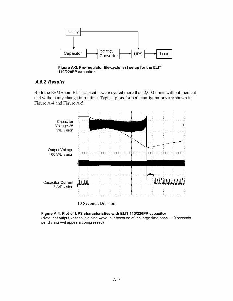
A-7
Figure A-3. Pre-regulator life-cycle test setup for the ELIT 110/220PP capacitor
A.8.2 Results
Both the ESMA and ELIT capacitor were cycled more than 2,000 times without incident and without any change in runtime. Typical plots for both configurations are shown in Figure A-4 and Figure A-5.
Capacitor Voltage 25 V/Division
Output Voltage 100 V/Division
Capacitor Current 2 A/Division
10 Seconds/Division
Figure A-4. Plot of UPS characteristics with ELIT 110/220PP capacitor (Note that output voltage is a sine wave, but because of the large time base—10 seconds per division—it appears compressed)
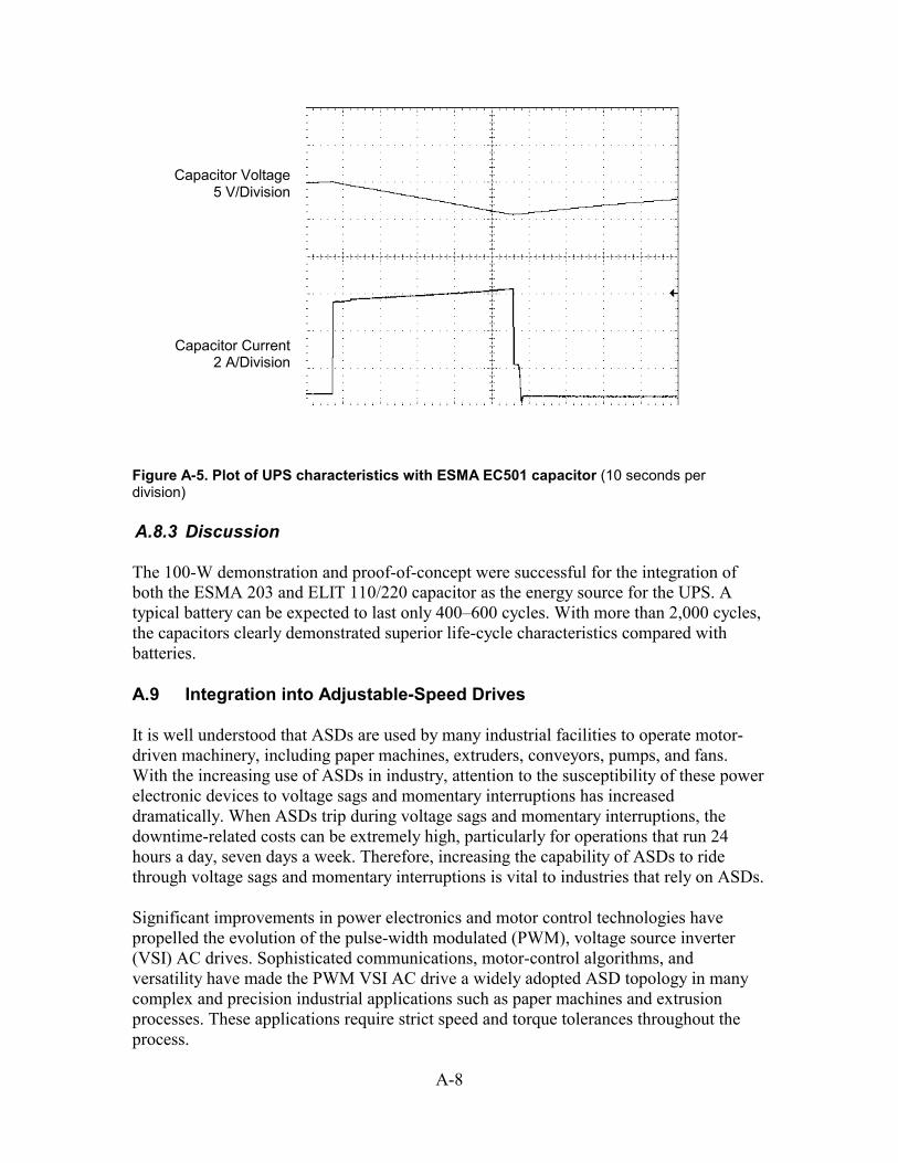
A-8
Capacitor Voltage 5 V/Division
Capacitor Current 2 A/Division
Figure A-5. Plot of UPS characteristics with ESMA EC501 capacitor (10 seconds per division)
A.8.3 Discussion
The 100-W demonstration and proof-of-concept were successful for the integration of both the ESMA 203 and ELIT 110/220 capacitor as the energy source for the UPS. A typical battery can be expected to last only 400–600 cycles. With more than 2,000 cycles, the capacitors clearly demonstrated superior life-cycle characteristics compared with batteries.
A.9 Integration into Adjustable-Speed Drives
It is well understood that ASDs are used by many industrial facilities to operate motor-driven machinery, including paper machines, extruders, conveyors, pumps, and fans. With the increasing use of ASDs in industry, attention to the susceptibility of these power electronic devices to voltage sags and momentary interruptions has increased dramatically. When ASDs trip during voltage sags and momentary interruptions, the downtime-related costs can be extremely high, particularly for operations that run 24 hours a day, seven days a week. Therefore, increasing the capability of ASDs to ride through voltage sags and momentary interruptions is vital to industries that rely on ASDs.
Significant improvements in power electronics and motor control technologies have propelled the evolution of the pulse-width modulated (PWM), voltage source inverter (VSI) AC drives. Sophisticated communications, motor-control algorithms, and versatility have made the PWM VSI AC drive a widely adopted ASD topology in many complex and precision industrial applications such as paper machines and extrusion processes. These applications require strict speed and torque tolerances throughout the process.
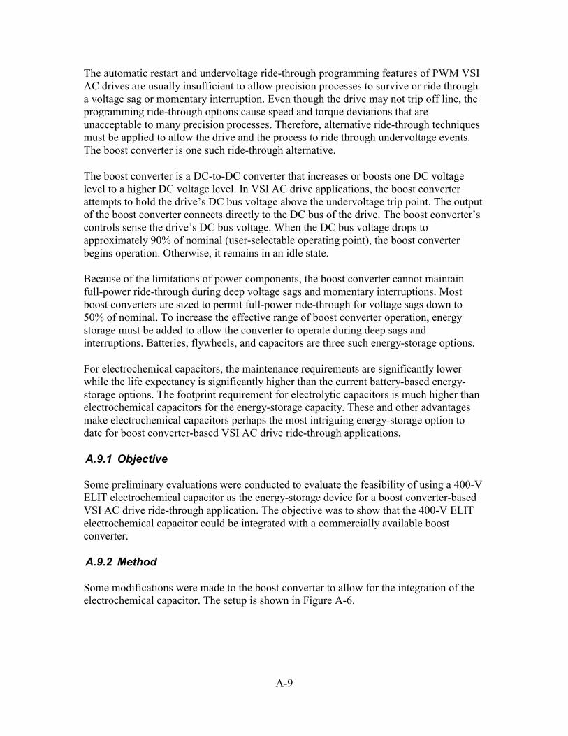
A-9
The automatic restart and undervoltage ride-through programming features of PWM VSI AC drives are usually insufficient to allow precision processes to survive or ride through a voltage sag or momentary interruption. Even though the drive may not trip off line, the programming ride-through options cause speed and torque deviations that are unacceptable to many precision processes. Therefore, alternative ride-through techniques must be applied to allow the drive and the process to ride through undervoltage events. The boost converter is one such ride-through alternative.
The boost converter is a DC-to-DC converter that increases or boosts one DC voltage level to a higher DC voltage level. In VSI AC drive applications, the boost converter attempts to hold the drive’s DC bus voltage above the undervoltage trip point. The output of the boost converter connects directly to the DC bus of the drive. The boost converter’s controls sense the drive’s DC bus voltage. When the DC bus voltage drops to approximately 90% of nominal (user-selectable operating point), the boost converter begins operation. Otherwise, it remains in an idle state.
Because of the limitations of power components, the boost converter cannot maintain full-power ride-through during deep voltage sags and momentary interruptions. Most boost converters are sized to permit full-power ride-through for voltage sags down to 50% of nominal. To increase the effective range of boost converter operation, energy storage must be added to allow the converter to operate during deep sags and interruptions. Batteries, flywheels, and capacitors are three such energy-storage options.
For electrochemical capacitors, the maintenance requirements are significantly lower while the life expectancy is significantly higher than the current battery-based energy-storage options. The footprint requirement for electrolytic capacitors is much higher than electrochemical capacitors for the energy-storage capacity. These and other advantages make electrochemical capacitors perhaps the most intriguing energy-storage option to date for boost converter-based VSI AC drive ride-through applications.
A.9.1 Objective
Some preliminary evaluations were conducted to evaluate the feasibility of using a 400-V ELIT electrochemical capacitor as the energy-storage device for a boost converter-based VSI AC drive ride-through application. The objective was to show that the 400-V ELIT electrochemical capacitor could be integrated with a commercially available boost converter.
A.9.2 Method
Some modifications were made to the boost converter to allow for the integration of the electrochemical capacitor. The setup is shown in Figure A-6.
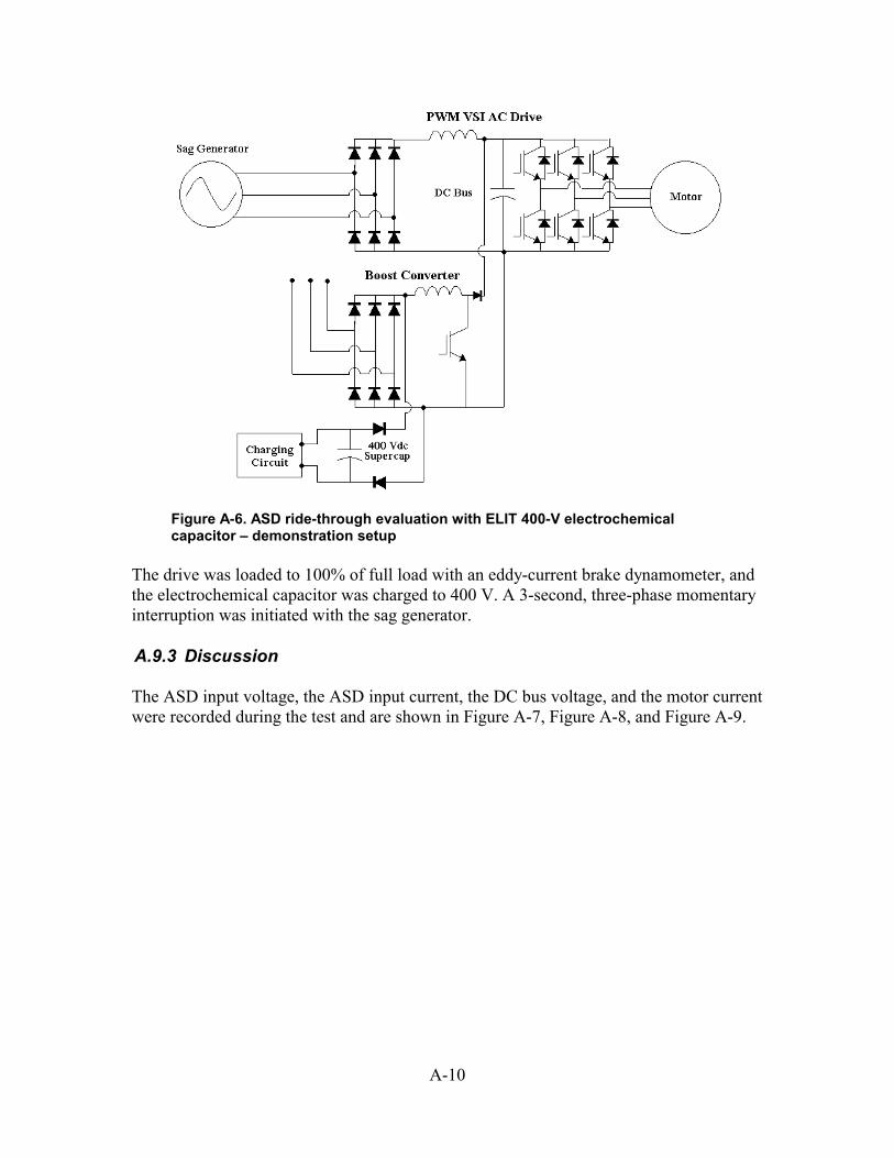
A-10
Figure A-6. ASD ride-through evaluation with ELIT 400-V electrochemical capacitor – demonstration setup
The drive was loaded to 100% of full load with an eddy-current brake dynamometer, and the electrochemical capacitor was charged to 400 V. A 3-second, three-phase momentary interruption was initiated with the sag generator.
A.9.3 Discussion
The ASD input voltage, the ASD input current, the DC bus voltage, and the motor current were recorded during the test and are shown in Figure A-7, Figure A-8, and Figure A-9.
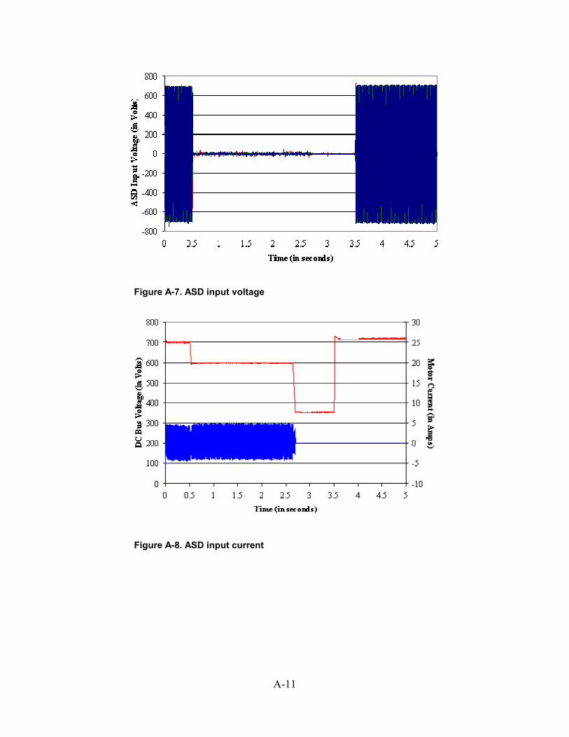
A-11
Figure A-7. ASD input voltage
Figure A-8. ASD input current
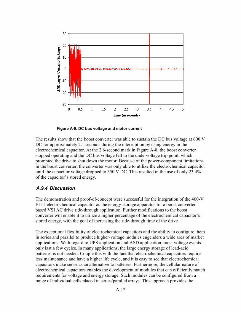
A-12
Figure A-9. DC bus voltage and motor current
The results show that the boost converter was able to sustain the DC bus voltage at 600 V DC for approximately 2.1 seconds during the interruption by using energy in the electrochemical capacitor. At the 2.6-second mark in Figure A-8, the boost converter stopped operating and the DC bus voltage fell to the undervoltage trip point, which prompted the drive to shut down the motor. Because of the power-component limitations in the boost converter, the converter was only able to utilize the electrochemical capacitor until the capacitor voltage dropped to 350 V DC. This resulted in the use of only 23.4% of the capacitor’s stored energy.
A.9.4 Discussion
The demonstration and proof-of-concept were successful for the integration of the 400-V ELIT electrochemical capacitor as the energy-storage apparatus for a boost converter-based VSI AC drive ride-through application. Further modifications to the boost converter will enable it to utilize a higher percentage of the electrochemical capacitor’s stored energy, with the goal of increasing the ride-through time of the drive.
The exceptional flexibility of electrochemical capacitors and the ability to configure them in series and parallel to produce higher-voltage modules engenders a wide area of market applications. With regard to UPS application and ASD application, most voltage events only last a few cycles. In many applications, the large energy storage of lead-acid batteries is not needed. Couple this with the fact that electrochemical capacitors require less maintenance and have a higher life cycle, and it is easy to see that electrochemical capacitors make sense as an alternative to batteries. Furthermore, the cellular nature of electrochemical capacitors enables the development of modules that can efficiently match requirements for voltage and energy storage. Such modules can be configured from a range of individual cells placed in series/parallel arrays. This approach provides the
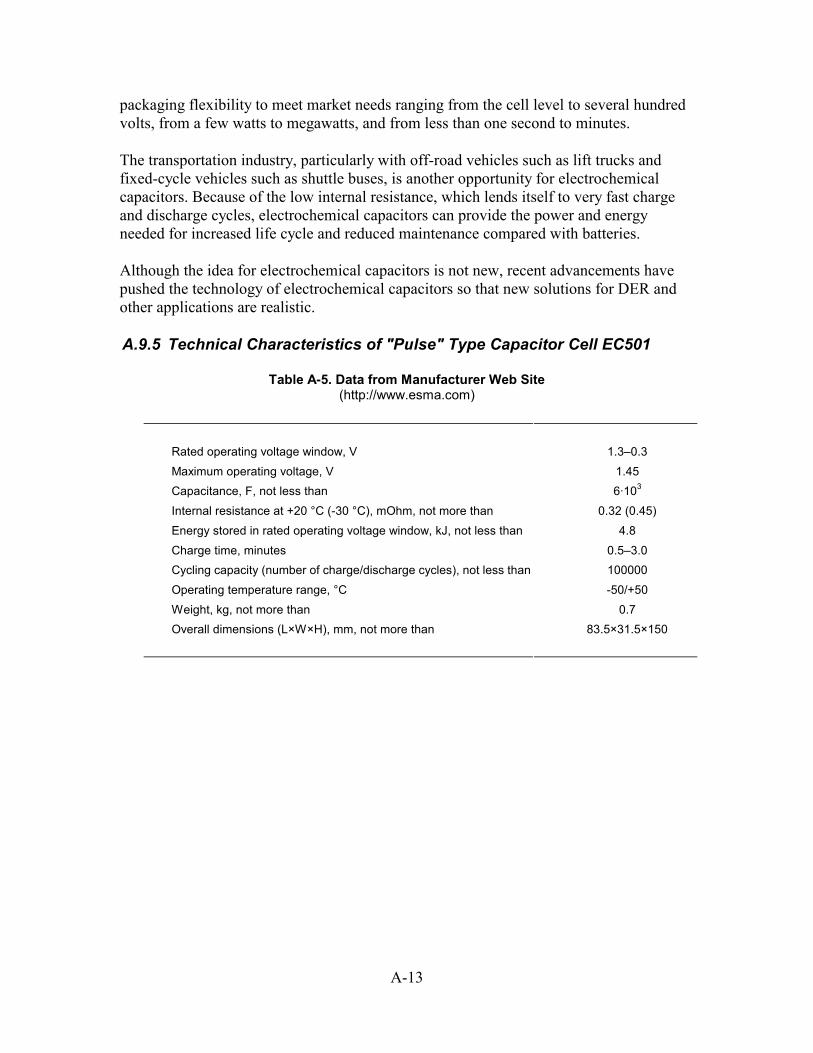
A-13
packaging flexibility to meet market needs ranging from the cell level to several hundred volts, from a few watts to megawatts, and from less than one second to minutes.
The transportation industry, particularly with off-road vehicles such as lift trucks and fixed-cycle vehicles such as shuttle buses, is another opportunity for electrochemical capacitors. Because of the low internal resistance, which lends itself to very fast charge and discharge cycles, electrochemical capacitors can provide the power and energy needed for increased life cycle and reduced maintenance compared with batteries.
Although the idea for electrochemical capacitors is not new, recent advancements have pushed the technology of electrochemical capacitors so that new solutions for DER and other applications are realistic.
A.9.5 Technical Characteristics of "Pulse" Type Capacitor Cell EC501
Table A-5. Data from Manufacturer Web Site (http://www.esma.com)
Rated operating voltage window, V 1.3–0.3 Maximum operating voltage, V 1.45 Capacitance, F, not less than 6·103 Internal resistance at +20 °C (-30 °C), mOhm, not more than 0.32 (0.45) Energy stored in rated operating voltage window, kJ, not less than 4.8 Charge time, minutes 0.5–3.0 Cycling capacity (number of charge/discharge cycles), not less than 100000 Operating temperature range, °C -50/+50 Weight, kg, not more than 0.7 Overall dimensions (L×W×H), mm, not more than 83.5×31.5×150
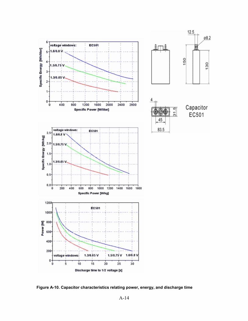
A-14
Figure A-10. Capacitor characteristics relating power, energy, and discharge time

REPORT DOCUMENTATION PAGE
Form Approved OMB NO. 0704-0188
Public reporting burden for this collection of information is estimated to average 1 hour per response, including the time for reviewing instructions, searching existing data sources, gathering and maintaining the data needed, and completing and reviewing the collection of information. Send comments regarding this burden estimate or any other aspect of this collection of information, including suggestions for reducing this burden, to Washington Headquarters Services, Directorate for Information Operations and Reports, 1215 Jefferson Davis Highway, Suite 1204, Arlington, VA 22202-4302, and to the Office of Management and Budget, Paperwork Reduction Project (0704-0188), Washington, DC 20503. 1. AGENCY USE ONLY (Leave blank)
2. REPORT DATE
June 2003
3. REPORT TYPE AND DATES COVERED
Subcontract Report
4. TITLE AND SUBTITLE Fast Response, Load-Matching Hybrid Fuel Cell: Final Technical Progress Report
6. AUTHOR(S) T.S. Key, H.E. Sitzlar, T.D. Geist
5. FUNDING NUMBERS
DP03.1001 NAD-1-30605-15
7. PERFORMING ORGANIZATION NAME(S) AND ADDRESS(ES)
EPRI PEAC Corp. 942 Corridor Park Blvd. Knoxville, TN 37932
8. PERFORMING ORGANIZATION
REPORT NUMBER
9. SPONSORING/MONITORING AGENCY NAME(S) AND ADDRESS(ES)
National Renewable Energy Laboratory 1617 Cole Blvd. Golden, CO 80401-3393
10. SPONSORING/MONITORING
AGENCY REPORT NUMBER NREL/SR-560-32743
11. SUPPLEMENTARY NOTES
NREL Technical Monitor: T. Basso 12a. DISTRIBUTION/AVAILABILITY STATEMENT
National Technical Information Service U.S. Department of Commerce 5285 Port Royal Road
Springfield, VA 22161
12b. DISTRIBUTION CODE
13. ABSTRACT (Maximum 200 words) Hybrid DER technologies interconnected with the grid can provide improved performance capabilities compared to a single power source, and, add value, when matched to appropriate applications. For example, in a typical residence, the interconnected hybrid system could provide power during a utility outage, and also could compensate for voltage sags in the utility service. Such a hybrid system would then function as a premium power provider and eliminate the potential need for an uninterruptible power supply. In this research project, a proton exchange membrane (PEM) fuel cell is combined with an asymmetrical ultracapacitor to provide robust power response to changes in system loading. This project also considers the potential of hybrid DER technologies to improve overall power system compatibility and performance. This report includes base year accomplishments of a proposed 3-year-option project:
• A review of grid-interconnection technical requirements
• Baseline testing of the PEM fuel cell and asymmetrical ultracapacitors as separate components
• Specifications for the hybrid fuel cell system with integrated energy storage
• Overview of the ultracapacitor technology selected for the hybrid system.
15. NUMBER OF PAGES
14. SUBJECT TERMS distributed energy; DER; grid interconnection; hybrid; PEM; fuel cell; ultracapacitor;
asymmetrical ultracapacitor; power response; EPRI PEAC; National Renewable Energy Laboratory; NREL; utility grid
16. PRICE CODE
17. SECURITY CLASSIFICATION
OF REPORT Unclassified
18. SECURITY CLASSIFICATION
OF THIS PAGE Unclassified
19. SECURITY CLASSIFICATION
OF ABSTRACT Unclassified
20. LIMITATION OF ABSTRACT
UL
NSN 7540-01-280-5500 Standard Form 298 (Rev. 2-89) Prescribed by ANSI Std. Z39-18 298-102