Embed Size (px)
Citation preview
Article
The International Journal of
Robotics Research
1–13
� The Author(s) 2015
Reprints and permissions:
sagepub.co.uk/journalsPermissions.nav
DOI: 10.1177/0278364915584806
ijr.sagepub.com
Hybrid motion/force control ofmulti-backbone continuum robots
Andrea Bajo and Nabil Simaan
Abstract
The recent growth of surgical applications exploiting continuum robots demands for new control paradigms that ensure
safety by controlling interaction forces of tele-operated end-effectors. In this paper, we present the modeling, sensing and
control of multi-backbone continuum robots in a unified framework for hybrid motion/force control. Multi-backbone conti-
nuum robots allow to estimate forces and torques at the operational point by monitoring loads along their actuation lines
without the need for a dedicated transducer at the operational point. This capability is indeed crucial in emerging fields
such as robotic surgery where cost and strict sterilization guidelines prevent the adoption of a dedicated sensor to provide
force feedback from the sterile field. To advance further the force sensing capabilities of multi-backbone continuum
robots, we present a new framework for hybrid motion and force control of continuum robots with intrinsic force sensing
capabilities. The framework is based on a kinetostatic modeling of the multi-backbone continuum robot with, a simplified
model for online estimate of the manipulator’s compliance, and a new strategy for merging force and motion control laws
in the configuration space of the manipulator. Experimental results show the ability to sense and regulate forces at the
operational point and evaluate the framework for shape exploration and stiffness imaging in flexible environments.
Keywords
Force control, continuum robots
1. Introduction
Successful and safe interaction with the environment
requires robotic manipulators to control motions and forces
at their operational point while complying with contact and
motion constraints (Khatib, 1987). When contact between
the robot’s end-effector and a rigid environment occurs,
reaction forces prevent motions in normal directions while
allowing translation of the contact point in the tangential
directions. These directions vary depending on contact and
friction between the two bodies (Mason and Salisbury,
1985).
There are mainly two methodologies to control interac-
tion forces and motions, impedance control (Hogan, 1985)
and hybrid motion/force control (Raibert and Craig, 1981).
Impedance control, a generalization of admittance control
(Whitney, 1977) and stiffness control (Salisbury, 1980),
aims at regulating the mechanical impedance of the opera-
tional point in contact with a rigid environment. As a conse-
quence, directions in which position should be controlled
accurately are assigned large impedance, while directions in
which the end-effector should comply with the environment
are assigned a small impedance. On the other hand, hybrid
motion/force control decouples control signals produced by
two independent motion and force controllers by projecting
their control signals into orthogonal directions in which
motions and forces should be independently controlled.
The main difference between the two methodologies is
that impedance control indirectly regulates force via a posi-
tion feedback, while hybrid motion/force control exploits
both position and force loops. The advantage of impedance
control is that mode switching at the time of contact and
accurate a priori knowledge of the geometric constraint and
elasticity of the environment are not necessary. On the other
hand, hybrid motion/force control requires a fairly accurate
knowledge of the contact constraint and may produce
unstable behaviors during the impact phase because of the
intermittent switching in control modes. However, when
the robotic manipulator is required to accurately control
position and force, the hybrid motion/force control provides
superior results. For the interested reader, an exhaustive
Advanced Robotics and Mechanism Applications (ARMA), Department
of Mechanical Engineering, Vanderbilt University, Nashville, TN, USA
Corresponding author:
Andrea Bajo, 2616 Erwin Road, Durham, NC 27705, USA.
Email: [email protected]
at VANDERBILT UNIVERSITY LIBRARY on August 5, 2015ijr.sagepub.comDownloaded from
overview of these two methods, variants and applications
are described in Yoshikawa (2000).
Continuum robots are continuously bending, compliant,
infinite-degree-of-freedom structures (Robinson and
Davies, 1999; Webster III and Jones, 2010) that have
gained steadily increasing attention by both the robotics
and medical communities. The innate compliance of these
devices makes them strong candidates for medical applica-
tions such as minimally invasive surgery (Simaan et al.,
2009), cardio-thoracic therapy (Camarillo et al., 2008),
neuro-surgery (Mahvash and Dupont, 2010) and unstruc-
tured tasks such as the grasping of unknown objects (Jones
and Walker, 2006). However, passive compliance comes
with a price of performance degradation in terms of posi-
tion accuracy, payload and force exchange capabilities.
Modeling of continuum robots builds upon the early
work on hyper-redundant manipulators where high-degree-
of-freedom structures were modeled using a modal repre-
sentation of backbone curves (Chirikjian and Burdick,
1994), splines (Zanganeh and Angeles, 1995) and a set of
differential equations (Chirikjian, 1993) minimizing the
strain energy along the backbone curve. The kinematics of
single- and multi-segment continuum robots was initially
presented as a series of natural basis functions (Gravagne
and Walker, 2000) and evaluated with bending and pris-
matic segments (Hannan and Walker, 2003). In an effort to
reduce the computational burden of these methods,
researchers focused on algorithms for real-time implemen-
tation (Jones and Walker, 2006) and closed-form solutions
based on the assumption of constant-curvature for tendon-
driven (Camarillo et al., 2008) and multi-backbone push-
pull segments (Xu and Simaan, 2010a).
Motion control of continuum robots is generally carried
out with a combination of three compensation strategies:
model-based, adaptive and close-loop. Model-based com-
pensation includes friction modeling (Kesner et al., 2011),
back-lash identification and correction (Agrawal et al.,
2010), extension of actuation lines (Xu and Simaan, 2006)
and kinematic coupling between serially-stacked segments
(Simaan et al., 2009). Adaptive control strategies that aug-
ment the model-based actuation compensation have also
been proposed using nonlinear observers (Ivanescu and
Stoian, 1995), sliding-mode controllers (Piltan and Tayebi
Haghighi, 2012), neural networks (Braganza et al., 2007)
and modeling of large deflection dynamics (Gravagne
et al., 2003). Finally, closed-loop control strategies include
a variegated use of sensors and multiple loops closed at dif-
ferent levels of the control framework. For example,
researchers have investigated single-camera vision algo-
rithms (Croom et al., 2010), multi-camera vision methods
(Camarillo et al., 2009), string pots and encoders (Trivedi
and Rahn, 2014) and electro-magnetic trackers (Penning
et al., 2011) to provide information about the current con-
figuration of the continuum manipulator. In an effort to
enhance further the control performance, scholars have
proposed mixed feedback controllers that uses both a joint-
space control loop and a configuration-space control loop
(Bajo et al., 2011), task-space closed-loop control (Penning
et al., 2011) and versatile controllers that are applicable
both to configuration-space and task-space control
(Kapadia et al., 2014).
As continuum robots are deployed in increasingly deli-
cate tasks and environments, researchers have recently
began investigating algorithms for stiffness control, com-
pliant motion control and indirect force control. In
Mahvash and Dupont (2011), the authors proposed a
method for combining the nominal forward kinematics
and the deflection of the manipulator due to the external
load to generate the desired tip stiffness. In Goldman
et al. (2014), the authors proposed a method that allows a
multi-backbone continuum robot to autonomously com-
ply to interaction forces acting at unknown locations. In
Kesner and Howe (2011), the authors proposed an indi-
rect force controller for flexible tendon-driven catheters.
To the best of the authors’ knowledge, there are no algo-
rithms for direct force control and hybrid/motion control
of continuum robots. This gap is mainly due to a lack of
sensorial technology able to miniaturize force sensors
and the formulation of a general framework that applies
to flexible manipulators.
In an effort to provide miniature robotic manipulators
with force feedback, researchers mainly investigated two
methodologies: 1) design and manufacturing of miniature
sensors for minimally invasive surgery (Baki et al., 2012;
Seibold et al., 2005; Valdastri et al., 2006); 2) algorithms
for intrinsic force sensing (Rucker and Webster III, 2011;
Wei and Simaan, 2012; Xu and Simaan, 2010b) Although
the first methodology provides a direct measure of the force
at the tip, its wide use is limited by cost, robustness, the
increasing demand of magnetic resonance imaging (MRI)
compatible surgical instruments, sterilizability and minia-
turization. On the other hand, the second methodology
views the entire robot as both a multi-axis force sensor and
a dexterous end-effector. The advantage of this approach is
that sensors are placed away from the surgical site reducing
the burden of providing sterilizable instruments.
This paper complements previous works aimed at pro-
viding multi-backbone continuum robots with a set of
modeling, estimation and control algorithms for full char-
acterization of their interaction with the environment. Full
characterization of the interaction includes: discerning col-
lisions, localizing contacts, estimating interaction forces
and autonomously complying with the environment at any
point along their flexible spine. In Xu and Simaan (2008,
2010b), a method for the estimation of wrenches at the tip
of a single- and multi-segment continuum robot was pro-
posed and validated. In Bajo and Simaan (2010, 2012), the
authors proposed the problem of contact detectably and
multiple algorithms for detection and localization of con-
tacts along multi-segment continuum robots. In Goldman
2 The International Journal of Robotics Research
at VANDERBILT UNIVERSITY LIBRARY on August 5, 2015ijr.sagepub.comDownloaded from

et al. (2014), an algorithm for compliant motion control of
continuum robots without a priori knowledge of interaction
points was presented. In Tully et al. (2012), the use of con-
tact detection and a constrained Kalman filter to register a
flexible robot to a flexible environment was demonstrated.
In Sanan et al. (2014), we extended this framework to
use force controlled scans of a flexible environment based
on the algorithm described in this work, to register shape
and stiffness maps of the environment to pre-operative
models.
The contribution of this work is a complete framework
for hybrid motion/force control of continuum robots with
force sensing capabilities. The force feedback can be pro-
vided by either a dedicated multi-axis force sensor at the
tip or one of the intrinsic force sensing methods proposed
in the literature. The force and position control signals are
merged in the configuration space of the continuum manip-
ulator via two transformations. The first transformation
computes the desired configuration space velocities that
achieve the desired task space velocities via the inverse
Jacobian matrix. The second transformation computes the
desired configuration space velocities that achieve the
desired task space forces via the compliance matrix of the
flexible manipulator. The joint-space control input is then
computed using the inverse position solution and a model-
based actuation compensation method. The actuation com-
pensation method has a twofold contribution: it compen-
sates for actuation line extensions and provides a feed-
forward term for the desired task space force to be applied
at the tip of the manipulator. The hybrid motion/force con-
trol framework for continuum robots is evaluated on a
multi-backbone continuum robot with intrinsic force sen-
sing that is suitable for minimally invasive surgery and nat-
ural orifice translumenal endoscopic surgery.
2. Assumptions
In this section, we outline the assumptions made in the
remainder of this work. First, we assume that the kinematic
model of the flexible manipulator is known and that the
robot is equipped with means for measuring or estimating
environmental interaction forces. This information would
be provided by intrinsic wrench estimation (Xu and
Simaan, 2008) or by a dedicated miniature multi-axis force
sensor placed at the operational point if the application
domain allows for use of such a sensor. In this work, a
multi-backbone continuum robot with intrinsic wrench esti-
mation capabilities is used to evaluate the hybrid motion/
force control framework. The following assumptions spe-
cifically apply to multi-backbone continuum robots with
intrinsic force sensing.
1. The continuum robot segments bend in circular shapes
and gravitational forces are negligible. This
assumption was verified in Xu and Simaan (2008,
2010a) for small robots such as the one used in this
work.
2. The continuum robot is able to sense actuation forces
via load cells placed between each actuation line and
its actuator. Examples of actuation units with force
sensing capabilities are provided in Xu and Simaan
(2008) and in Goldman et al. (2013).
3. The geometric constraint is known and the environ-
ment is rigid. This information is used for both the
hybrid motion/force controller and the intrinsic wrench
estimation. However, because of the innate compliance
of continuum robots as demonstrated by experimental
results, an exact knowledge of the geometric constraint
is not necessary.
4. The only interaction point between the continuum
robot and the environment is at the operational point.
5. An approximate model of the compliance matrix of
the continuum manipulator is available, the force
control-loop rate is adequate and the interaction force
at the operational point of the robot is not sufficiently
large to cause large deformations of the continuum
structure. This assumption was verified in Goldman
et al. (2014).
3. Modeling of the multi-backbone continuum
robot
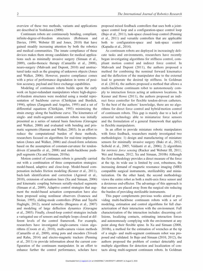
Figure 1 shows a one segment multi-backbone continuum
robot mounted on a linear stage capable of controlling
insertion depth qins along the bz0-axis of the world
frame. The segment has three push-pull backbones that
allows for bending its end disk in space. A complete deri-
vation of the direct and differential kinematics of these con-
tinuum structures are given in Xu and Simaan (2008) and
Simaan et al. (2009). For the ease of presentation, in the
remainder of this section, the kinematics and statics of the
manipulator are summarized. Six coordinate systems are
defined: 1) world frame fbx0, by0,bz0g; 2) base disk frame
fbx1, by1,bz1g; 3) bending plane frame fbx2, by2,bz2g; 4) end-
disk frame fbx3, by3,bz3g; 5) gripper frame fbx4, by4,bz4g; 6)
probe frame fbx5, by5,bz5g.The position, p0
0, 5, and the orientation, R05, of the probe
frame {O5} are uniquely defined by configuration variables
C = u d qins½ �T . Angle u is defined between vectors bz5
and bx2. Angle d is defined about bz1 between vector bx1 and
the bending plane. Finally, qins is the distance between
frame {O0} and frame {O1}. The pose of the end-effector
is then given by
p00, 5 = p0
0, 1 +R02p
22, 3 +R0
4p44, 5 ð1Þ
R05 =R0
1R12R
23R
34R
45 ð2Þ
Bajo and Simaan 3
at VANDERBILT UNIVERSITY LIBRARY on August 5, 2015ijr.sagepub.comDownloaded from
where pki, j is the vector from the origin of frame {Oi} to the
origin of frame {Oj} written in frame {Ok} and matrix Rij
represents the rotation from frame {Oj} to frame {Oi}.
In order to achieve angles u and d, the secondary back-
bones of the continuum robot (i = 1, 2, 3) are shortened or
lengthened as follows
qi = r cos dið Þ u� u0ð Þ ð3Þ
where di =d + (i 2 1)b, b = 2/3p and r is the radial dis-
tance of each secondary backbone from the centrally-
located backbone. From equation (3), we define the aug-
mented joint-space vector q 2IR4 as
q= q1 q2 q3 qins½ �T ð4Þ
The end-effector’s twist, t, is related to the rate of change
of the configurations space variables, _C, and the rate of
change of the joint space variables, _q, as
t= Jtc_C ð5Þ
_q= JqC_C ð6Þ
where Jtc is the geometric Jacobian relating configuration-
space and task-space velocities and JqC is the Jacobian
relating configuration-space and joint-space velocities.
Using virtual work arguments discussed in Simaan et al.
(2009), the following first order linear relationship relates
the actuation forces t to the configuration space vector Cand an external wrench we acting at the operational point
JTtCwe + JT
qCt =rU ð7Þ
where U is the elastic energy stored by the continuum seg-
ment, and rU = ∂U∂C
.
By defining fc = JTtCWe as the generalized force vector,
equation (7) yields
fc =rU � JTqc
h it =rU � Jqc
� �Tt ð8Þ
For small perturbations from an equilibrium configura-
tion, the stiffness of the continuum segment is described in
configuration space as
dfc =Kcdc ð9Þ
where the stiffness is given by the Jacobian of the compo-
nents of the generalized force associated with the conti-
nuum robot with respect to its configuration space
perturbation as described in Goldman et al. (2014).
The robot’s actuation lines stretch and compress due to
their inherent flexibility. Therefore, actuation compensation
methods need to be considered in order to achieve the
desired configuration C of the continuum segment. In Xu
and Simaan (2006) and Simaan et al. (2009) several model-
based estimation algorithms were presented in order to deal
with actuation compensation of multi-backbone continuum
robots. The compensation law is based on a compliance
model of the actuation lines and the expected actuation
forces t as obtained from equation (7). The expected
stretch/compression on the actuation lines is obtained by
e =Cat ð10Þ
where the compliance matrix of the actuation lines Ca is
given by
Ca =Lal
EyA
I3× 3 0
0 0
� �ð11Þ
and Lal is the length of the actuation lines, Ey is the Young’s
modulus of Nickel-Titanium (NiTi) and A is the cross-
sectional area of the backbones. By accounting for the
compliance model, the desired backbone displacement is
then computed as
bqdes = qdes + e ð12Þ
where qdes are the desired joint values as defined in equa-
tion (4) based on a pure kinematic calculation and bqdes also
includes the actuation compensation law e.
Fig. 1. Kinematics nomenclature used in this paper.
4 The International Journal of Robotics Research
at VANDERBILT UNIVERSITY LIBRARY on August 5, 2015ijr.sagepub.comDownloaded from
4. Hybrid motion/force control for continuum
robots
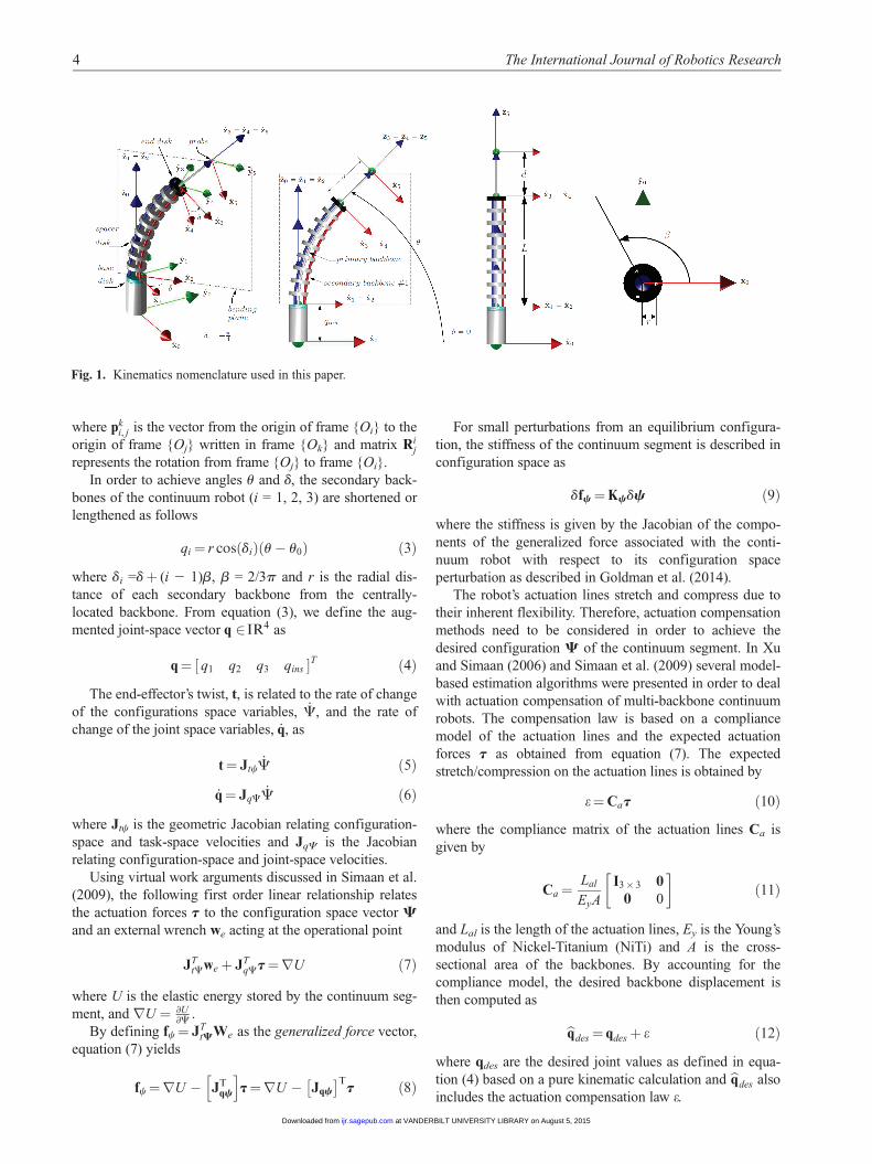
Figure 2 shows the proposed hybrid motion/force control
architecture of multi-backbone continuum robots with
intrinsic force sensing. As in the classic architecture pro-
posed in Khatib (1987), two separate controllers produce
motion and force commands that are transformed into
allowable motion/force directions using projection matrices
Vm and Vf. The main difference in the proposed approach
lies on the fact that the motion and force control commands
are merged in configuration space of the continuum manip-
ulator rather than in the actuator space as in the classic
approach. In the reminder of this section, we provide justi-
fication and details of this control architecture starting with
the task decomposition through the use of projection
matrices.
4.1. Projection matrices
Hybrid motion/force control aims at controlling the force
interaction by decoupling control inputs into allowable
relative motions and constraining wrenches1
. Regardless of
the type of contact, two dual vector subspaces are defined
(Featherstone, 2004; Lipkin and Duffy, 1988), one n-
dimensional space of normal vectors N4 F6 and one (6-n)-
dimensional space of tangent vectors T4 M6, where n is
the degree of motion constraint. The bases of these two
spaces are defined by a 6 × n matrix N and a 6 × (6 2
n) matrix T. The columns of N and T are respectively any
n linearly independent wrench in N and any 6 2 n linearly
independent motion screws in T. As a consequence of the
reciprocity condition and the contact constraint, the scalar
product of any column of N with any column of T is zero.
Although in many situations matrices N and T are simply
the composition of canonical vectors in IR6 and can be
obtained by inspection (Mason, 1981), this is not the case
when dealing with complex interaction tasks and multi-
point contacts (Featherstone, 2004; Lipkin and Duffy,
1988).
The reciprocity of the control inputs is enforced by pro-
jecting each control input into the correct subspace by pre-
multiplication of a projection matrix. We therefore define
two projection matrices Vf and Vm that project any control
input into consistent wrenches and twists respectively
Of =N(NTN)�1NT ð13Þ
Om =T(TTT)�1TT = I� Of ð14Þ
It is worth noticing that equations (13) and (14) provide
only two particular projection matrices. A general formula-
tion that expresses general projections consistent with the
given contact is discussed in Basilevsky (1983) and
Featherstone (2004).
4.2. Configuration space projection
In the control of rigid-body robots, the dynamics of the
manipulator is used to convert motion commands into
actuator torque commands. Using this approach, the units
of the output of the force and motion controllers are consis-
tent (typically torques). This approach is not directly appli-
cable to small continuum manipulators because these
robots are inherently flexible, their masses very small and
the dynamics of these robots is usually poorly characterized
due to large friction and modeling uncertainties. Therefore,
we propose to project control commands into the config-
uration space of the continuum robot. An estimate of the
robot compliance allows to maintain the units consistency
between the motion and the force controller branches.
The projection of the motion controller commands from
task space to configuration space is achieved by multiplying
Fig. 2. Proposed hybrid motion/force control of multi-backbone continuum robots with intrinsic force sensing. Vm and Vf are
projection matrices, Jxc is the Jacobian matrix, Kc is the configuration-space stiffness matrix, C is the configuration space vector, Ka
is the joint-space stiffness matrix.
Bajo and Simaan 5
at VANDERBILT UNIVERSITY LIBRARY on August 5, 2015ijr.sagepub.comDownloaded from

the twist by the inverse of the Jacobian matrix Jtc thus
resulting in configuration space speeds _Cm. The projection
of the force controller commands from task space to config-
uration space is achieved through the use of the transpose
of the Jacobian matrix Jtc which results in generalized force
fc. Using an estimate of the continuum robot compliance as
presented in Goldman et al. (2014), fc is then transformed
into kinematically- and unit-consistent configuration space
speeds _Cf by pre-multiplying it with the configuration
space compliance matrix K�1C . The commanded resultant
configuration space speed is then given by
_C = _Cm + _Cfc ð15Þ
Hence, the inverse position analysis of the continuum
robot segment is used to calculate the theoretical desired
joint-space positions qdes. Using the intrinsic force sensing
approach in Appendix A the wrench acting at the tip of the
robot is estimated and substituted into equation (7). An
additional joint-level actuation compensation term is then
obtained using equation (10). This term includes both a
compensation term for the applied wrench at the tip of the
robot and a compensation term for extension and friction
in the actuation lines.
4.3. Control architecture
The framework inputs are defined by the reference twist
tref = vTref vT
ref
� �Tand the reference interaction wrench
at the operational point wref = fTref mTref
h iT
.
The reference end-effector twist and wrench are related
to a desired twist tdes and a desired wrench wdes that are
then used as inputs to low level motion and force control-
lers before conversion into configuration speed commands.
Depending on the particular application, tdes may be equal
to tref if speed is directly commanded by the user (e.g.
direct speed telemanipulation control by the user) or tdes
may be obtained directly from the end-effector position/
orientation error using a resolved rates algorithm (e.g.
Whitney (1969)). The desired wrench wdes is obtained
using a proportional-integral force feedback control scheme
such that
wdes =Kf , pwe +Kf , i
Zwe ð16Þ
where Kf,p and Kf,i are the proportional and integral feed-
back gains and we is the wrench error defined as
we =wref � wcurr ð17Þ
and wref, wcurr represent the reference and current estimated
end-effector wrench, respectively.
The desired twist tdes and wrench wdes are then transformed
into desired configuration speeds _Cm and _Cfc to reconcile the
units of the motion and force controller outputs
_Cm = JtcyOmtdes ð18Þ
_Cfc =K�1C JT
tcOf wdes ð19Þ
Once the desired configuration space velocity vector is
obtained, a resolved motion rate approach (Whitney, 1969)
is used to obtain the desired configuration and exploit the
inverse pose solution.
Next, the controller generates joint-level commands to
accomplish the desired tasks. Due to the flexibility of the
actuation lines, compensation is required for both achieving
the desired pose and applying the desired wrench at the
end-effector. Such actuation compensation methods were
described in Xu and Simaan (2006) and Simaan et al.
(2009). Using the static model proposed in equation (7)
and the desired force wref, the actuation compensation law
is obtained as in equation (12).
4.4. Compensation of uncertainties
During control of the real continuum robot there will be a
deviation l between the desired actuation force vector tdes
and the sensed actuation force vector tcurr. This deviation
is due to friction and extension in the actuation lines, per-
turbation of the bending shape from the ideal circular con-
figuration, and geometric and static parameters. Thus, the
sensed actuation force vectors is as follows
tcurr = tdes + l ð20Þ
In Goldman et al. (2014), the authors showed that the
force deviation l is a function of the configurations C of
the manipulator and the joint-space velocities _q. Several
methods have been proposed in order to characterize fric-
tion and uncertainties. For example, in Mahvash and
Okamura (2006), the authors proposed a discrete Dahl
model for friction compensation in a master console. In
Penning et al. (2011), the authors included a Dahl friction
model into the control architecture of steerable catheters.
In Lock and Dupont (2011), the authors proposed a
method for friction estimation and compensation in con-
centric tube robots. In Goldman et al. (2014), the authors
used a nonlinear regression via support vector regressors
to compensate for lumped uncertainties in multi-back-
bone, multi-segment continuum robots. In this work, we
experimentally evaluated uncertainties vector l across
the robot’s workspace and populated a lookup table for
real-time control.
5. Experimental results
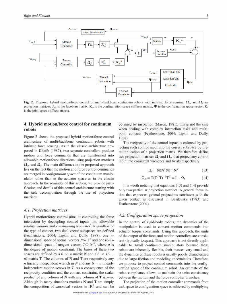
The proposed control framework was implemented on the
one-segment multi-backbone continuum robot of Figure 3.
Three experiments are presented in the reminder of this
section: force regulation in the bx0- and by0-directions, shape
estimation and stiffness characterization. The continuum
segment is able to translate along the insertion axis (axis bz0
in Figure 1) providing the end-effector with a total of three
degree-of-freedom (Dof); qins and angles u and d. Intrinsic
6 The International Journal of Robotics Research
at VANDERBILT UNIVERSITY LIBRARY on August 5, 2015ijr.sagepub.comDownloaded from
wrench estimation was implemented according to
Appendix B while assuming point contact at the robot tip.
Multiple experiments were carried out to validate the effi-
cacy of the proposed framework. While the motion control-
ler always controls motion along the insertion axis
direction (the estimation algorithm is not able to sense
forces in the bz0 -direction (Xu and Simaan, 2008)), the
force controller switches between regulating a force in thebx0- or by0-directions depending on the task. Table 1 pro-
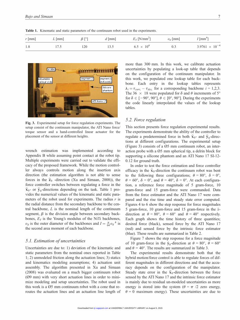
vides the numerical values of the kinematic and static para-
meters of the robot used for experiments. The radius r is
the radial distance from the secondary backbone to the cen-
tral backbone, L is the nominal length of the continuum
segment, b is the division angle between secondary back-
bones, EY is the Young’s modulus of the NiTi backbones,
od is the outer diameter of the backbones and I = p64
od4 is
the second area moment of each backbone.
5.1. Estimation of uncertainties
Uncertainties are due to: 1) deviation of the kinematic and
static parameters from the nominal ones reported in Table
1; 2) unmodeled friction along the actuation lines; 3) statics
and kinematics modeling assumptions; 4) actuation unit
assembly. The algorithm presented in Xu and Simaan
(2008) was evaluated on a much bigger continuum robot
(Ø9 mm) with very short actuation lines in order to mini-
mize modeling and setup uncertainties. The robot used in
this work is a Ø5 mm continuum robot with a cone that re-
routes the actuation lines and an actuation line length of
more than 300 mm. In this work, we calibrate actuation
uncertainties by populating a look-up table that depends
on the configuration of the continuum manipulator. In
this work, we populated one lookup table for each back-
bone. Each entry in the lookup tables represents
li = tcurri� tdesi
for a corresponding backbone i = 1,2,3.
The 36 × 18 were populated for d and u increments of 5�for d 2 [290�, 90�], u 2 [0�, 90�]. During the experiments
the code linearly interpolated the values of the lookup
tables.
5.2. Force regulation
This section presents force regulation experimental results.
The experiments demonstrate the ability of the controller to
regulate a predetermined force in both bx0- and by0-direc-
tions at different configurations. The experimental setup
(Figure 3) consists of a Ø5 mm continuum robot, an inter-
action probe with a Ø5 mm spherical tip, a delrin block for
supporting a silicone phantom and an ATI Nano 17 SI-12-
0.12 for ground truth.
In order to test the force estimation and force controller
efficacy in the bx0-direction the continuum robot was bent
to the following three configurations; u = 80�, d = 0�,
u = 60�, d = 0�, and u = 40�, d = 0�. At each configura-
tion, a reference force magnitude of 5 gram-force, 10
gram-force and 15 gram-force were commanded. Data
from the force estimator and the ATI Nano 17 were com-
pared and the rise time and steady state error computed.
Figures 4 to 6 show the step response for force magnitudes
5 gram-force, 10 gram-force and 15 gram-force in the x-
direction at u = 80�, u = 60� and u = 40� respectively.
Each graph shows the time history of three quantities;
desired force (black), sensed force by the ATI Nano 17
(red) and sensed force by the intrinsic force estimator
(blue). These results are summarized in Table 2.
Figure 7 shows the step response for a force magnitude
of 10 gram-force in the y0-direction at u = 80�, u = 60�and u = 40�. The results are summarized in Table 3.
The experimental results demonstrate both that the
hybrid motion/force control is able to regulate forces of dif-
ferent magnitudes in different directions and that the accu-
racy depends on the configuration of the manipulator.
Steady state error in the bx0-direction between the force
sensed by the ATI Nano 17 and the intrinsic force estimator
is mainly due to residual un-modeled uncertainties as more
energy is stored into the system (u = p /2 zero energy,
u = 0 maximum energy). These uncertainties are due to
Fig. 3. Experimental setup for force regulation experiments. The
setup consist of the continuum manipulator, the ATI Nano force/
torque sensor and a hand-controlled linear actuator for the
placement of the sensor at different heights.
Table 1. Kinematic and static parameters of the continuum robot used in the experiments.
r [mm] L [mm] b [�] d [mm] EY [N/mm2] od [mm] I [mm4]
1.8 17.5 120 13.5 6.5 × 10⁴ 0.3 3.9761 × 1024
Bajo and Simaan 7
at VANDERBILT UNIVERSITY LIBRARY on August 5, 2015ijr.sagepub.comDownloaded from
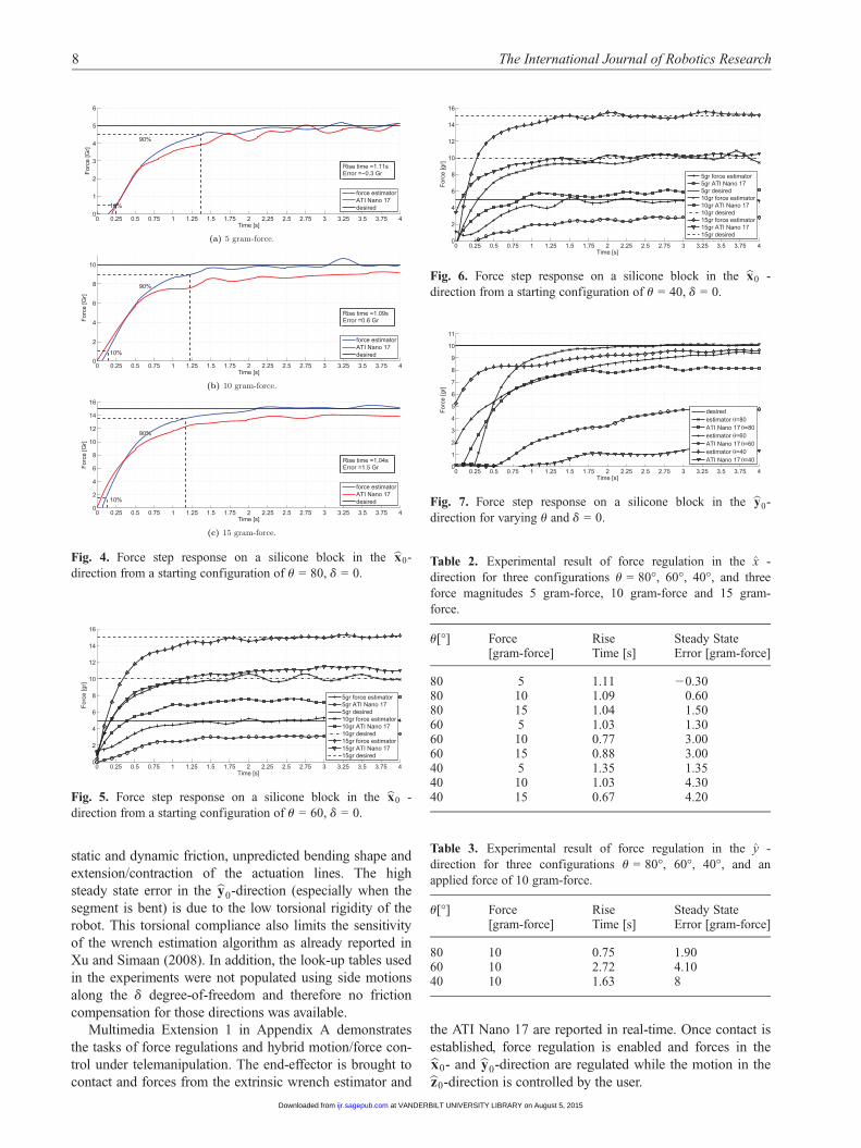
static and dynamic friction, unpredicted bending shape and
extension/contraction of the actuation lines. The high
steady state error in the by0-direction (especially when the
segment is bent) is due to the low torsional rigidity of the
robot. This torsional compliance also limits the sensitivity
of the wrench estimation algorithm as already reported in
Xu and Simaan (2008). In addition, the look-up tables used
in the experiments were not populated using side motions
along the d degree-of-freedom and therefore no friction
compensation for those directions was available.
Multimedia Extension 1 in Appendix A demonstrates
the tasks of force regulations and hybrid motion/force con-
trol under telemanipulation. The end-effector is brought to
contact and forces from the extrinsic wrench estimator and
the ATI Nano 17 are reported in real-time. Once contact is
established, force regulation is enabled and forces in thebx0- and by0-direction are regulated while the motion in thebz0-direction is controlled by the user.
0 0.25 0.5 0.75 1 1.25 1.5 1.75 2 2.25 2.5 2.75 3 3.25 3.5 3.75 40
1
2
3
4
5
6
Time [s]
Forc
e [G
r]
force estimatorATI Nano 17desired10%
90%
Rise time =1.11sError =−0.3 Gr
(a) 5 gram-force.
0 0.25 0.5 0.75 1 1.25 1.5 1.75 2 2.25 2.5 2.75 3 3.25 3.5 3.75 40
2
4
6
8
10
Time [s]
Forc
e [G
r]
force estimatorATI Nano 17desired10%
90%
Rise time =1.09sError =0.6 Gr
(b) 10 gram-force.
0 0.25 0.5 0.75 1 1.25 1.5 1.75 2 2.25 2.5 2.75 3 3.25 3.5 3.75 40
2
4
6
8
10
12
14
16
Time [s]
Forc
e [G
r]
force estimatorATI Nano 17desired10%
90%
Rise time =1.04sError =1.5 Gr
(c) 15 gram-force.
Fig. 4. Force step response on a silicone block in the bx0-
direction from a starting configuration of u = 80, d = 0.
0 0.25 0.5 0.75 1 1.25 1.5 1.75 2 2.25 2.5 2.75 3 3.25 3.5 3.75 40
2
4
6
8
10
12
14
16
Time [s]
Forc
e [g
r]
5gr force estimator5gr ATI Nano 175gr desired10gr force estimator10gr ATI Nano 1710gr desired15gr force estimator15gr ATI Nano 1715gr desired
Fig. 5. Force step response on a silicone block in the bx0 -
direction from a starting configuration of u = 60, d = 0.
0 0.25 0.5 0.75 1 1.25 1.5 1.75 2 2.25 2.5 2.75 3 3.25 3.5 3.75 40
2
4
6
8
10
12
14
16
Time [s]
Forc
e [g
r]
5gr force estimator5gr ATI Nano 175gr desired10gr force estimator10gr ATI Nano 1710gr desired15gr force estimator15gr ATI Nano 1715gr desired
Fig. 6. Force step response on a silicone block in the bx0 -
direction from a starting configuration of u = 40, d = 0.
0 0.25 0.5 0.75 1 1.25 1.5 1.75 2 2.25 2.5 2.75 3 3.25 3.5 3.75 40
1
2
3
4
5
6
7
8
9
10
11
Time [s]
Forc
e [g
r]
desiredestimator θ=80ATI Nano 17 θ=80estimator θ=60ATI Nano 17 θ=60estimator θ=40ATI Nano 17 θ=40
Fig. 7. Force step response on a silicone block in the by0-
direction for varying u and d = 0.
Table 2. Experimental result of force regulation in the x -
direction for three configurations u = 80�, 60�, 40�, and three
force magnitudes 5 gram-force, 10 gram-force and 15 gram-
force.
u[�] Force[gram-force]
RiseTime [s]
Steady StateError [gram-force]
80 5 1.11 20.3080 10 1.09 0.6080 15 1.04 1.5060 5 1.03 1.3060 10 0.77 3.0060 15 0.88 3.0040 5 1.35 1.3540 10 1.03 4.3040 15 0.67 4.20
Table 3. Experimental result of force regulation in the y -
direction for three configurations u = 80�, 60�, 40�, and an
applied force of 10 gram-force.
u[�] Force[gram-force]
RiseTime [s]
Steady StateError [gram-force]
80 10 0.75 1.9060 10 2.72 4.1040 10 1.63 8
8 The International Journal of Robotics Research
at VANDERBILT UNIVERSITY LIBRARY on August 5, 2015ijr.sagepub.comDownloaded from
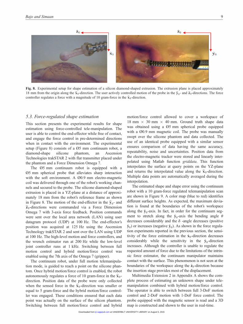
5.3. Force-regulated shape estimation
This section presents the experimental results for shape
estimation using force-controlled tele-manipulation. The
user is able to control the end-effector while free of contact,
and engage the force control in pre-determined directions
when in contact with the environment. The experimental
setup (Figure 8) consists of a Ø5 mm continuum robot, a
diamond-shape silicone phantom, an Ascension
Technologies trakSTAR 2 with flat transmitter placed under
the phantom and a Force Dimension Omega 7.
The Ø5 mm continuum robot is equipped with a
Ø5 mm spherical probe that alleviates sharp interaction
with the soft environment. A Ø0.9 mm electro-magnetic
coil was delivered through one of the robot’s working chan-
nels and secured to the probe. The silicone diamond-shaped
extrusion is placed in a YZ-plane at a distance of approxi-
mately 18 mm from the robot’s reference frame as shown
in Figure 8. The motion of the end-effector in the by0- andbz0-directions were commanded via a Force Dimension
Omega 7 with 3-axis force feedback. Position commands
were sent over the local area network (LAN) using user
datagram protocol (UDP) at 100 Hz. The end-effector’s
position was acquired at 125 Hz using the Ascension
Technology trakSTAR 2 and sent over the LAN using UDP
at 100 Hz. The high-level motion and force controllers, and
the wrench estimator run at 200 Hz while the low-level
joint controller runs at 1 kHz. Switching between full
motion control and hybrid motion/force control was
enabled using the 7th axis of the Omega 7 (gripper).
The continuum robot, under full motion telemanipula-
tion mode, is guided to reach a point on the silicone phan-
tom. Once hybrid motion/force control is enabled, the robot
autonomously regulates a force of 10 gram-force in the bx0-
direction. Position data of the probe were only collected
when the sensed force in the bx0-direction was smaller or
equal to 5 gram-force and the hybrid motion/force control-
ler was engaged. These conditions ensured that each data
point was actually on the surface of the silicon phantom.
Switching between full motion/force control and hybrid
motion/force control allowed to cover a workspace of
18 mm × 30 mm × 40 mm. Ground truth shape data
was obtained using a Ø5 mm spherical probe equipped
with a Ø0.9 mm magnetic coil. The probe was manually
swept over the silicone phantom and data collected. The
use of an identical probe equipped with a similar sensor
ensures comparison of data having the same accuracy,
repeatability, noise and uncertainties. Position data from
the electro-magnetic tracker were stored and linearly inter-
polated using Matlab function griddata. This function
interpolates the surface at query points on the YZ-plane
and returns the interpolated value along the bx0-direction.
Multiple data points are automatically averaged during the
interpolation.
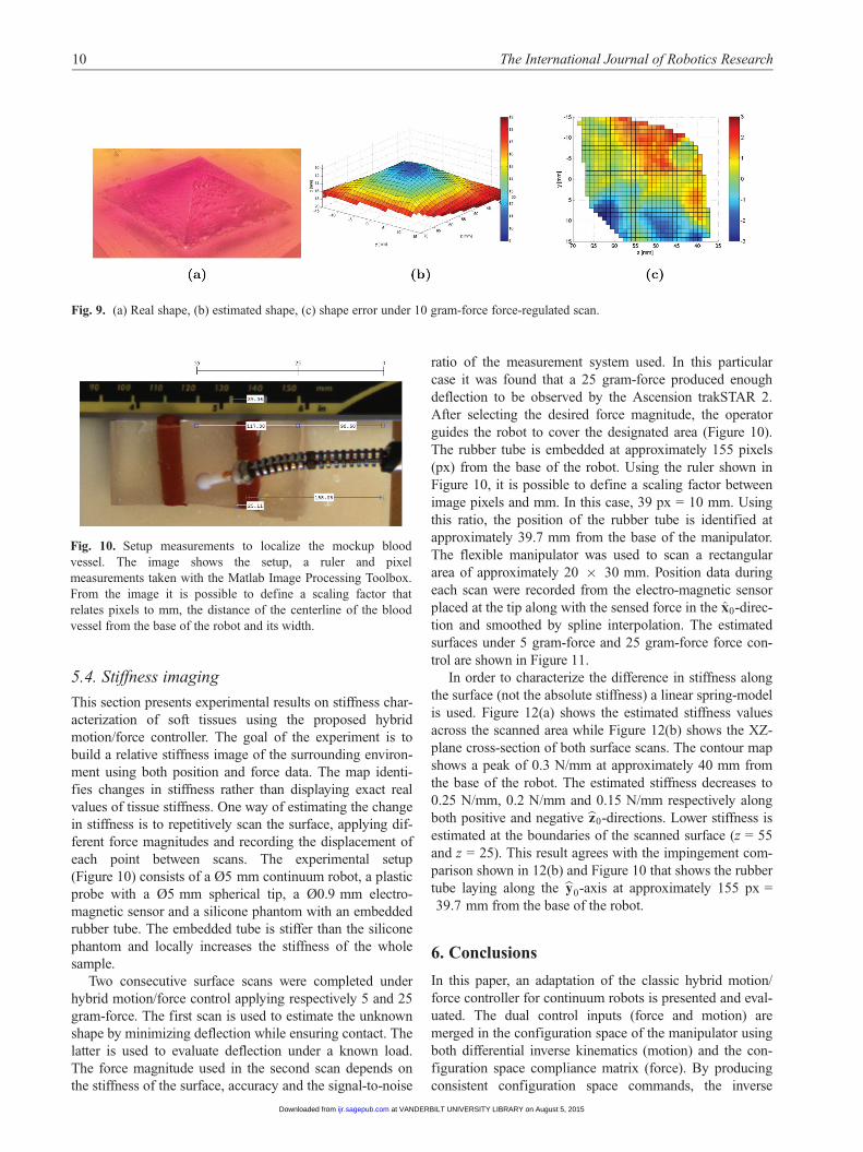
The estimated shape and shape error using the continuum
robot with a 10 gram-force regulated telemanipulation scan
are shown in Figure 9. A color map (blue to red) identifies
different surface heights. As expected, the maximum devia-
tion is found at the boundaries of the robot’s workspace
along the y0-axis. In fact, in order for the continuum seg-
ment to stretch along the y0-axis the bending angle u
decreases considerably and the d -angle decreases (positive
y0) or increases (negative y0). As shown in the force regula-
tion experiments reported in the previous section, the sensi-
tivity of the force estimation in the x0-direction decreases
considerably while the sensitivity in the y0-direction
increases. Although the controller is unable to regulate the
requested amount of force due to the limitations of the intrin-
sic force estimator, the continuum manipulator maintains
contact with the surface. This phenomenon is not seen at the
boundaries of the workspace along the z0-direction because
the insertion stage provides most of the displacement.
Multimedia Extension 2 in Appendix A shows the com-
plete process of estimating an unknown shape under tele-
manipulation combined with hybrid motion/force control.
The operator is able to switch between full 3-DoF motion
control and 2-DoF motion with 1-DoF force control. The
probe equipped with the magnetic sensor is read and a 3D
map is constructed and shown to the user in real-time.
Fig. 8. Experimental setup for shape estimation of a silicon diamond-shaped extrusion. The extrusion plane is placed approximately
18 mm from the origin along the bx0-direction. The user actively controlled motion of the probe in the by0- and bz0-directions. The force
controller regulates a force with a magnitude of 10 gram-force in the bx0-direction.
Bajo and Simaan 9
at VANDERBILT UNIVERSITY LIBRARY on August 5, 2015ijr.sagepub.comDownloaded from
5.4. Stiffness imaging
This section presents experimental results on stiffness char-
acterization of soft tissues using the proposed hybrid
motion/force controller. The goal of the experiment is to
build a relative stiffness image of the surrounding environ-
ment using both position and force data. The map identi-
fies changes in stiffness rather than displaying exact real
values of tissue stiffness. One way of estimating the change
in stiffness is to repetitively scan the surface, applying dif-
ferent force magnitudes and recording the displacement of
each point between scans. The experimental setup
(Figure 10) consists of a Ø5 mm continuum robot, a plastic
probe with a Ø5 mm spherical tip, a Ø0.9 mm electro-
magnetic sensor and a silicone phantom with an embedded
rubber tube. The embedded tube is stiffer than the silicone
phantom and locally increases the stiffness of the whole
sample.
Two consecutive surface scans were completed under
hybrid motion/force control applying respectively 5 and 25
gram-force. The first scan is used to estimate the unknown
shape by minimizing deflection while ensuring contact. The
latter is used to evaluate deflection under a known load.
The force magnitude used in the second scan depends on
the stiffness of the surface, accuracy and the signal-to-noise
ratio of the measurement system used. In this particular
case it was found that a 25 gram-force produced enough
deflection to be observed by the Ascension trakSTAR 2.
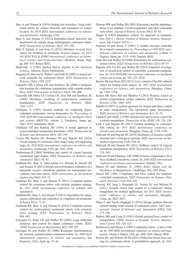
After selecting the desired force magnitude, the operator
guides the robot to cover the designated area (Figure 10).
The rubber tube is embedded at approximately 155 pixels
(px) from the base of the robot. Using the ruler shown in
Figure 10, it is possible to define a scaling factor between
image pixels and mm. In this case, 39 px = 10 mm. Using
this ratio, the position of the rubber tube is identified at
approximately 39.7 mm from the base of the manipulator.
The flexible manipulator was used to scan a rectangular
area of approximately 20 × 30 mm. Position data during
each scan were recorded from the electro-magnetic sensor
placed at the tip along with the sensed force in the x0-direc-
tion and smoothed by spline interpolation. The estimated
surfaces under 5 gram-force and 25 gram-force force con-
trol are shown in Figure 11.
In order to characterize the difference in stiffness along
the surface (not the absolute stiffness) a linear spring-model
is used. Figure 12(a) shows the estimated stiffness values
across the scanned area while Figure 12(b) shows the XZ-
plane cross-section of both surface scans. The contour map
shows a peak of 0.3 N/mm at approximately 40 mm from
the base of the robot. The estimated stiffness decreases to
0.25 N/mm, 0.2 N/mm and 0.15 N/mm respectively along
both positive and negative bz0-directions. Lower stiffness is
estimated at the boundaries of the scanned surface (z = 55
and z = 25). This result agrees with the impingement com-
parison shown in 12(b) and Figure 10 that shows the rubber
tube laying along the by0-axis at approximately 155 px =
39.7 mm from the base of the robot.
6. Conclusions
In this paper, an adaptation of the classic hybrid motion/
force controller for continuum robots is presented and eval-
uated. The dual control inputs (force and motion) are
merged in the configuration space of the manipulator using
both differential inverse kinematics (motion) and the con-
figuration space compliance matrix (force). By producing
consistent configuration space commands, the inverse
Fig. 10. Setup measurements to localize the mockup blood
vessel. The image shows the setup, a ruler and pixel
measurements taken with the Matlab Image Processing Toolbox.
From the image it is possible to define a scaling factor that
relates pixels to mm, the distance of the centerline of the blood
vessel from the base of the robot and its width.
Fig. 9. (a) Real shape, (b) estimated shape, (c) shape error under 10 gram-force force-regulated scan.
10 The International Journal of Robotics Research
at VANDERBILT UNIVERSITY LIBRARY on August 5, 2015ijr.sagepub.comDownloaded from

position of the manipulator is used along with model-based
actuation compensation methods and feed-forward force-
inputs. The framework was evaluated on a single-segment
continuum robot suitable for natural orifice translumenal
endoscopic surgery. Firstly, experiments demonstrated the
ability to estimate and regulate forces at the tip of the
robot. The controller’s performances are tied to the intrinsic
force estimator’s sensitivity and accuracy. Secondly, force-
regulated shape estimation of unknown flexible environ-
ments was demonstrated. The force controller ensured that
the probe maintained contact with the tissue phantom.
Finally, force-regulated stiffness estimation of unknown
flexible environments was conducted. Force and position
data from subsequent scans with different forces were com-
pared and a linear stiffness model was used to produce a
stiffness image of the explored workspace. The experi-
ments demonstrated that this strategy allows discernment
of change in stiffness. The framework proposed in this
work makes the first step toward improving situation
awareness, estimation and mapping in challenging environ-
ments such as minimally invasive robotic surgery. The pro-
posed algorithm was already used in a proof of concept of
simultaneous localization and mapping of body organs
(BodySLAM) (Sanan et al., 2014) by providing simulta-
neous shape and stiffness information of soft environments.
Future work will demonstrate the proposed framework on
multi-segment continuum robots and provide efficient and
precise algorithms for shape estimation and stiffness ima-
ging (Goldman et al., 2012) in deep surgical sites.
Funding
This work was supported by the National Science Foundation
(NSF) (grant number IIS-1063750) and in part by grant number
IIS -1327566.
Note
1. Here we adopt the notation of axis coordinates for motion
screws ðT = ½vT0 ,v
T �T Þ where v0 is the linear velocity and v
is the angular velocity. We also adopt the ray coordinate repre-
sentation for wrenches (F = [fT,mT]T) where f is a force vector
and M is a moment.
References
Agrawal V, Peine WJ, Yao B and Choi S (2010) Control of cable
actuated devices using smooth backlash inverse. In: 2010 IEEE
international conference on robotics and automation, Ancho-
rage, USA, pp. 1074–1079.
Bajo A, Goldman RE and Simaan N (2011) Configuration
and joint feedback for enhanced performance of multi-
segment continuum robots. In: 2011 IEEE international
conference on robotics and automation, Shanghai, China.
Shanghai: IEEE.
Fig. 11. (a) Colormap of the estimated surface applying 5 gram-force, (b) Colormap of the estimated surface applying 25 gram-force.
Fig. 12. (a) Contour map of the estimated stiffness, (b) XZ-plane cross section of the two scans used to estimate the stiffness.
Bajo and Simaan 11
at VANDERBILT UNIVERSITY LIBRARY on August 5, 2015ijr.sagepub.comDownloaded from
Bajo A and Simaan N (2010) Finding lost wrenches: Using conti-
nuum robots for contact detection and estimation of contact
location. In: 2010 IEEE international conference on robotics
and automation, Anchorage, USA.
Bajo A and Simaan N (2012) Kinematics-based detection and
localization of contacts along multisegment continuum robots.
IEEE Transactions on Robotics 28(2): 291–302.
Baki P, Szekely G and Kosa G (2012) Miniature tri-axial force
sensor for feedback in minimally invasive surgery. In: 2012
4th IEEE RAS & EMBS international conference on biome-
dical robotics and biomechatronics (BioRob), Roma, Italy,
pp. 805–810. Roma: IEEE.
Basilevsky A (1983) Applied Matrix Algebra in the Statistical
Sciences. Mineola: Dover Publications.
Braganza D, Dawson D, Walker I and Nath N (2007) A neural net-
work controller for continuum robots. IEEE Transactions on
Robotics 23(6): 1270–1277.
Camarillo DB, Carlson CR and Salisbury JK (2009) Configura-
tion tracking for continuum manipulators with coupled tendon
drive. IEEE Transactions on Robotics 25(4): 798–808.
Camarillo DB, Milne CF, Carlson CR, Zinn MR and Salisbury JK
(2008) Mechanics modeling of tendon-driven continuum
manipulators. IEEE Transaction on Robotics 24(6):
1262–1273.
Chirikjian G (1993) General methods for computing hyper-
redundant manipulator inverse kinematics. In: Proceedings of
1993 IEEE/RSJ international conference on intelligent robots
and systems (IROS’93), volume 2, Yokohama, Japan, pp.
1067–1073. Yokohama: IEEE.
Chirikjian GS and Burdick JW (1994) A modal approach to
hyper-redundant manipulator kinematics. IEEE Transaction on
Robotics and Automation 10(3): 343–354.
Croom JM, Rucker DC, Romano JM and Webster RJI (2010)
Visual sensing of continuum robot shape using self-organizing
maps. In: 2010 IEEE international conference on robotics and
automation, Anchorage, USA, pp. 4591–4596.
Featherstone R (2004) Modeling and control of contact between
constrained rigid bodies. IEEE Transaction on Robotics and
Automation 20(1): 82–92.
Goldman RE, Bajo A, MacLachlan LS, Pickens R, Herrell SD
and Simaan N (2013) Design and performance evaluation of a
minimally invasive telerobotic platform for transurethral sur-
veillance and intervention. IEEE transactions on bio-medical
engineering 60(4): 918–25.
Goldman RE, Bajo A and Simaan N (2011) Compliant motion
control for continuum robots with intrinsic actuation sensing.
In: 2011 IEEE international conference on robotics and
automation.
Goldman RE, Bajo A and Simaan N (2012) Algorithms for auton-
omous exploration and estimation in compliant environments.
Robotica 31(1): 71–87.
Goldman RE, Bajo A and Simaan N (2014) Compliant motion
control for multisegment continuum robots with actuation
force sensing. IEEE Transactions on Robotics 30(4):
890–902.
Gravagne IA, Rahn CD and Walker ID (2003) Large deflection
dynamics and control for planar continuum robots. IEEE/
ASME Transaction on Mechatronics 8(2): 299–307.
Gravagne IA and Walker ID (2000) Kinematic transformations
for remotely-actuated planar continuum robots. In: 2000 IEEE
international conference on robotics and automation, San
Francisco, USA, April, pp. 19–26.
Hannan MW and Walker ID (2003) Kinematics and the implemen-
tation of an elephant’ s trunk manipulator and other continuum
style robots. Journal of Robotic Systems 20(2): 45–63.
Hogan N (1985) Impedance control: An approach to manipula-
tion: Part I – Theory. Journal of Dynamic Systems, Measure-
ment, and Control 107(1): 1.
Ivanescu M and Stoian V (1995) A variable structure controller
for a tentacle manipulator. In: Proceedings of 1995 IEEE inter-
national conference on robotics and automation, volume 3,
Nagoya, Japan, pp. 3155–3160. Nagoya: IEEE.
Jones BA and Walker ID (2006) Kinematics for multisection con-
tinuum robots. IEEE Transactions on Robotics 22(1): 43–57.
Kapadia AD, Fry KE and Walker ID (2014) Empirical investiga-
tion of closed-loop control of extensible continuum manipula-
tors. In: 2014 IEEE/RSJ international conference on intelligent
robots and systems, pp. 329–335. IEEE.
Kesner SB and Howe RD (2011) Force control of flexible catheter
robots for beating heart surgery. In: 2011 IEEE international
conference on robotics and automation, Shanghai, China,
pp. 1589–1594.
Kesner SB, Howe RD and Member S (2011) Position control of
motion compensation cardiac catheters. IEEE Transaction on
Robotics 27(6): 1045–1055.
Khatib O (1987) A unified approach for motion and force control
of robot manipulators: The operational space formulation.
IEEE Journal of Robotics and Automation 3(1): 43–53.
Lipkin H and Duffy J (1988) Hybrid twist and wrench control for
a robotic manipulator. Transaction of the ASME 110: 138–144.
Lock J and Dupont PE (2011) Friction modeling in concentric
tube robots. In: 2011 IEEE international conference on
robotics and automation, Shanghai, China, pp. 1139–1146.
Mahvash M and Dupont PE (2010) Mechanics of dynamic needle
insertion into a biological material. IEEE transactions on bio-
medical engineering 57(4): 934–43.
Mahvash M and Dupont PE (2011) Stiffness control of surgical
continuum manipulators. IEEE Transaction on Robotics 27(2):
334–345.
Mahvash M and Okamura AM (2006) Friction compensation for a
force-feedback telerobotic system. In: 2006 IEEE international
conference on robotics and automation, Orlando, USA.
Mason M and Salisbury K (1985) Robot Hands and the
Mechanics of Manipulation. Cambridge, MA: MIT Press.
Mason MT (1981) Compliance and force control for computer
controlled manipulators. IEEE Transaction on Systems, Man,
and Cybernetics 11(6): 418–432.
Penning RS, Jung J, Borgstadt JA, Ferrier NJ and Michael R
(2011) Towards closed loop control of a continuum robotic
manipulator for medical applications. In: 2011 IEEE interna-
tional conference on robotics and automation, Shanghai,
China, pp. 4822–4827.
Piltan F and Tayebi Haghighi S (2012) Design gradient descent
optimal sliding mode control of continuum robots. IAES Inter-
national Journal of Robotics and Automation (IJRA) 1(4):
175–189.
Raibert MH and Craig JJ (1981) Hybrid position/force control of
manipulators. ASME Journal of Dynamic Systems Measure-
ment Control 102: 126–133.
Robinson G and Davies J (1999) Continuum robots - a state of the
art. In: 1999 IEEE International conference on robotics and auto-
mation, volume 4, Detroit, USA, pp. 2849–2854. Denver: IEEE.
Rucker DC and Webster III RJ (2011) Deflection-based force sen-
sing for continuum robots: A probabilistic approach. In: 2011
12 The International Journal of Robotics Research
at VANDERBILT UNIVERSITY LIBRARY on August 5, 2015ijr.sagepub.comDownloaded from
IEEE/RSJ international conference on intelligent robots and
systems, pp. 3764–3769.
Salisbury J (1980) Active stiffness control of a manipulator in car-
tesian coordinates. In: 1980 19th IEEE conference on decision
and control including the symposium on adaptive processes,
pp. 95–100.
Sanan S, Tully S, Bajo A, Simaan N and Choset H (2014) Simul-
taneous compliance and registration estimation for robotic sur-
gery. In: Robotics science and systems, Berkeley, USA, 12–16
July.
Seibold U, Kubler B and Hirzinger G (2005) Prototype of instru-
ment for minimally invasive surgery with 6-axis force sensing
capability. In: IEEE international conference on robotics and
automation, Barcelona, Spain, pp. 498–503.
Simaan N, Xu K, Wei W, Kapoor A, Kazanzides P, Taylor RH and
Flint P (2009) Design and integration of a telerobotic system
for minimally invasive surgery of the throat. The International
Journal of Robotics Research 28(9): 1134–1153.
Trivedi D and Rahn CD (2014) Model-based shape estimation for
soft robotic manipulators: The planar case. Journal of Mechan-
isms and Robotics 6(2): 021005.
Tully S, Bajo A, Kantor G, Choset H and Simaan N (2012) Con-
strained filtering with contact detection data for the localization
and registration of continuum robots in flexible environments.
In: 2012 IEEE international conference on robotics and auto-
mation, St. Paul, USA.
Valdastri P, Harada K, Menciassi A, Beccai L, Stefanini C, Fujie
M and Dario P (2006) Integration of a miniaturised triaxial
force sensor in a minimally invasive surgical tool. IEEE trans-
actions on bio-medical engineering 53(11): 2397–2400.
Webster III RJ and Jones BA (2010) Design and kinematic mod-
eling of constant curvature continuum robots: A review. The
International Journal of Robotics Research 29(13): 1661–
1683.
Wei W and Simaan N (2012) Modeling, force sensing, and con-
trol of flexible cannulas for microstent delivery. Journal of
Dynamic Systems, Measurement, and Control 134(4):
041004.
Whitney DE (1969) Resolved motion rate control of manipulators
and human prostheses. IEEE Transactions on Man-Machine
Systems 10(2): 47–53.
Whitney DE (1977) Force feedback control of manipulator fine
motions. Journal of Dynamic Systems, Measurement, and Con-
trol 99(2): 91.
Xu K and Simaan N (2006) Actuation compensation for flexible
surgical snake-like robots with redundant remote actuation. In:
2006 IEEE international conference on robotics and automa-
tion, Orlando, USA, May, pp. 4148–4154.
Xu K and Simaan N (2008) An investigation of the intrinsic force
sensing capabilities of continuum robots. IEEE Transactions
on Robotics 24(3): 576–587.
Xu K and Simaan N (2010a) Analytic formulation for kinematics,
statics, and shape restoration of multibackbone continuum
robots via elliptic integrals. ASME Journal of Mechanisms and
Robotics 2(1): 011006–011006–13.
Xu K and Simaan N (2010b) Intrinsic wrench estimation and its
performance index for multisegment continuum robots. IEEE
Transactions on Robotics 26(3): 555–561.
Yoshikawa T (2000) Force control of robot manipulators. In: 2000
IEEE international conference on robotics and automation,
San Francisco, USA, April, pp. 220–226.
Zanganeh KE and Angeles J (1995) The inverse kinematics of
hyper-redundant manipulators using splines. In: 1995 IEEE
international conference on robotics and automation, Nagoya,
Japan.
Appendix A: Index to Multimedia Extensions
Archives of IJRR multimedia extensions published prior to
2014 can be found at http://www.ijrr.org, after 2014 all
videos are available on the IJRR YouTube channel at http://
www.youtube.com/user/ijrrmultimedia
Table of Multimedia Extensions
Appendix B: Intrinsic wrench estimation
Continuum robots with actuation force sensing allow to
estimate external wrenches acting at the tip. These capabil-
ities are investigated in Xu and Simaan (2008) where the
authors presented a minimization algorithm for estimating
forces with a single segment and presented the full estima-
tion in Xu and Simaan (2010b). For completeness, this
appendix summarizes the results from Xu and Simaan
(2008, 2010b) while assuming point contact at the tip of the
robot. Using the statics model in equation (7), the external
wrench acting at the tip of the continuum robot is given by
wcurr = JTtc
� �y rU� JT
qc tcurr � lð Þ� �
+ I� JTtc
� �yJT
tc
� �h
ð21Þwhere
h =DyFTSe wse � JTtc
� �y rU� JT
qc tcurr � lð Þ� �� �
ð22Þ
D= I� JTtc
� �yJT
tc
� �T
Se I� JTtc
� �yJT
tc
� �ð23Þ
F= I� JTtc
� �yJT
tc
� �ð24Þ
Se =bnt × bnnð Þ bnt × bnnð ÞT 03× 3
03× 3 I3× 3
� �ð25Þ
Wse =ctbnt + ntbnn
03× 1
� �ð26Þ
Se and Wse contain a priori knowledge of the contact con-
straint and guide the estimation algorithm. The a priori
knowledge is defined by contact normal vector bnn and con-
tact tangential vector bnt. These two vectors define the plane
in which the sensable component of the external wrench
lies.
Extension Media type Description
1 Video Hybrid motion/force control2 Video Real-time shape estimation under
telemanipulation control
Bajo and Simaan 13
at VANDERBILT UNIVERSITY LIBRARY on August 5, 2015ijr.sagepub.comDownloaded from