Embed Size (px)
Citation preview
IEEJ Journal of Industry ApplicationsVol.8 No.6 pp.967–974 DOI: 10.1541/ieejjia.8.967
Paper
Hybrid Motion Reproduction Using Master/Slave TypeMotion-Copying System
Satoshi Nishimura∗ Member, Seiichiro Katsura∗ Senior Member
(Manuscript received May 1, 2018, revised April 7, 2019)
This paper proposes a hybrid motion reproduction structure using a master-slave structure manipulator based on amotion-copying system. Data-driven control will be an important technique in the near future. Learning from Demon-stration (LfD) using a robot manipulator is already used in manufacturing. Unlike other motion observation methodsbased on visual or trajectory responses, a motion-copying system can obtain not only trajectory response but also forceresponse during contact motion, which is necessary to realize contact tasks. A motion-copying system has two phases,the motion saving phase and motion reproduction phase. In the motion reproduction phase, the motion stored in themotion saving phase obtained from the bilateral control can be used to reproduce specific motion. Existing controlmethods for a motion-copying system have only one system in the reproduction phase, a slave system. It is necessaryto consider the case where there are two systems in the phase to widen the application of a motion-copying system.The additional system can provide flexibility to the reproduced motion. In this case, data, human, and a robot areinvolved in reproducing the motion. In this paper, the control structure is proposed when there are two systems in themotion reproduction phase. Because there are two systems, it is necessary to design the controllers for each system.The proposed method uses a coordinate transformation technique to design two motions in each system separately.The paper also introduces a novel index called the reproduction ratio. It determines the motion to be reproduced in themotion reproduction phase. The ratio is used as an element of a coordinate transformation matrix. The experimentalresults show the validity of the proposed method.
Keywords: acceleration control, position control, force control, modal transformation, motion-copying system
1. Introductions
In recent years, motion transfer technique to robot manip-ulators is attracting attention. By realizing the technique, itcan be expanded to many applications. To name a few, it canbe used in manufacturing factories, education sites, etc. Ifrobots can mimic the motion of human workers in factories,the number of workers can be reduced. Or, if a robot remem-bers the movement of a skilled person, the robot becomes ateacher that can teach the motion to trainees.
There can be two ways to transfer motion to robots; the firstways is to transmit and use it in realtime, while the other wayis to use the motion afterward. Bilateral control is a usefultechnique to transmit haptic sensation between two places,consequently transferring motion to remote robots. Researchof bilateral control has been done since the 1940s. Goertz etal. proposed the first bilateral mechanism (1). Since the birthof bilateral control, numbers of control structures were in-troduced to transmit haptic sensation clearly (2). To name afew, there are force reflecting structure (3), impedance reflect-ing structure (4), two-channel structure (5), three-channel struc-ture (6), etc. Transparency is one of the famous indices to ex-amine haptic sensation transmission performance (7). It viewsthe system as a two-port circuit, and the relationship betweencontrol variables represented by transfer functions are used
∗ Department of System Design Engineering, Keio University3-14-1, Hiyoshi, Kohoku-ku, Yokohama 223-8522, Japan
to show how precisely the sensation can be sent. Those aremore specific indices to express how light the system is andhow well the impedance of a contact object is reproduced ina remote system by dividing the transfer function in contactmotion into two. Among many structures, acceleration-basedfour channel bilateral control has the best transparency or op-erationality and reproducibility (8).
The other way of using the motion is to utilize after mak-ing robots learn the motion. There are several ways to ob-tain a demonstration motion. Motion storing using visualinformation is one way to observe human motion (9); how-ever, it is very difficult to analyze contact motions becauseit is very difficult to extract contact force during the motion.There are other ways to obtain human motion information,such as using IMU sensors; however, the problem still ex-ists. A motion-copying system is a powerful tool to storemotion with haptic sensation (10). It solves the problem by us-ing a bilateral control system to obtain not only trajectoryinformation but also information of contact force. A motion-copying system consists of two phases. The first phase is amotion storing phase, and the other is a motion reproductionphase. The motion is stored by obtaining the response of themaster system in bilateral control. Then, the responses areloaded to a system to reproduce the stored movement. Its ap-plication area is very wide. Nowadays, there are many robotmanipulators such as Baxter (11) that can be used for motiontraining once the motion is obtained. It can be used to ser-vice robots for them to realize more human-like motion (12).
c© 2019 The Institute of Electrical Engineers of Japan. 967
Hybrid Motion Reproduction Using Master/Slave Type Motion-Copying System(Satoshi Nishimura et al.)
Control of data-driven systems (13) has become to attract at-tention, meaning that there will be an increasing opportunityfor the motion-copying system to be an essential techniquefor these systems. The motion obtained can also be used toanalyze human motion (14).
One of the challenging problems in a motion-copying sys-tem is to improve the flexibility of the stored motion. Ex-amples of flexibility mean adapting to a loading environmentwhen it is different from the one in the saving phase, or ex-panding the situation to use the stored motion itself. Discus-sion about the adaptiveness has been done in many papers.The adaptability to loading environments can be improvedby changing control stiffness during the motion reproductionphase (15). Mode-based reproduction was also considered (16) tomake the problem similar to that in bilateral control. Positioncontrol and force control based motion-copying systems wereproposed (17) so that the control stiffness can be designed fromzero to infinite. The report (18) defines control stiffness whenreproducing motion, indicating that the value can be designedfrom zero to infinite by changing the control structure in themotion reproduction phase.
Even though there are researches to improve the reproduc-tion performance in a motion-copying system, there are veryfew reports that discuss to use a master/slave type manipu-lator in the motion reproduction phase. By using the mas-ter/slave type manipulator, it can obtain both forces indepen-dently based on the fact from bilateral control. The mas-ter/slave structure gives the flexibility to a standard motion-copying system. For example, an operator in the master sys-tem can provide the adaptability to the saved motion becausea human has higher adaptability than robots. It can also beimplemented to a training system when storing the skilledmotion and learning the movement using the master system.Data/human hybrid motion reproduction is required to beconsidered. However, since the number of actuator increases,the connectivity of each system becomes complicated. In thiscase, two problems are required to be solved: what kind ofconstraint should be given to the master system, and whatmotion to reproduce in the slave system.
In this paper, the hierarchal coordinate transformationtechnique is used to design two problems separately. Trans-forming saved and reproducing master responses to anothercoordinate realizes to consider the average motion and themotion difference between the two. The difference betweenthe saved motion and the motion being performed at the mas-ter system in the motion reproduction phase is considered togive a constraint to the master system. The average motion isused to reproduce the motion in the slave system. To definethe average motion, the index called the reproduction ratio isnewly defined. The reproduction ratio is defined as the in-fluence of external force in motion saving and reproductionphase on the trajectory response to the slave system. The de-sign of the reproduction ratio realizes hybrid motion repro-duction.
The paper is organized as follows. In section 2, bilateralcontrol and a standard motion-copying system are shown. Insection 3, the proposed structure is derived. Section 4 ex-plains the experimental results to show the validity of theproposed method, and the paper is concluded in the last.
2. Motion-Copying System
As it is mentioned in the Introduction, a motion-copyingsystem consists of two phases: the motion saving phase andmotion reproduction phase. This section explains both phasesin turn. The paper uses a disturbance observer (DOB) (19) foracceleration dimension control and a reaction force observer(RFOB) (20) for sensor-less external force estimation. The pa-per also assumes that the cut-off frequencies of the DOB andRFOB are high enough.2.1 Motion Saving Phase Human motion is going to
be obtained by using bilateral control. Control goals of bilat-eral control are defined as
f DBm + f DB
s = 0, · · · · · · · · · · · · · · · · · · · · · · · · · · · · · · · · (1)
xDBm − xDB
s = 0, · · · · · · · · · · · · · · · · · · · · · · · · · · · · · · · · · (2)
where f and x stand for force and position responses, re-spectively. The subscripts m and s stand for the variablesfor the master and slave systems. The superscript DB indi-cates the variable in the motion saving phase. To realize eachcontrol goal independently, the values are mapped from theworkspace to a modal space by using a coordinate transfor-mation matrix, which is called a quarry matrix. The quarrymatrix is
Q =1
2
[1 11 −1
]. · · · · · · · · · · · · · · · · · · · · · · · · · · · · · · · · · (3)
The relationship between variables in the workspace andthose in the modal space is expressed as
f DBv = Q f DB,
xDBv = QxDB,
f DBv =
[f DBc f DB
d
]T, f DB =
[f DBm f DB
s
]T,
xDBv =
[xDB
c xDBd
]T, xDB =
[xDB
m xDBs
]T,
where the subscripts v indicates the vector of the modalspace. The subscripts c, and d, which are called as the vari-ables of the common mode and differential mode, stand forthe variable in the modal space, respectively. Accelerationreferences for both modes are calculated as
xDB refc = Cf ( f cmd
c − f DBc ), · · · · · · · · · · · · · · · · · · · · · · · (4)
xDB refd = Cp(xcmd
d − xDBd ), · · · · · · · · · · · · · · · · · · · · · · · (5)
where Cf and Cp stand for the force and position controllers,respectively. Cf is the P controller, while Cp is the PDcontroller. The superscript cmd and ref stand for the com-mand value and reference value. The command values aref cmdc = 0, xcmd
d = 0. Acceleration references for each sys-tem are calculated by retransforming (4) and (5), which arethe values in the modal space, into the workspace by usingthe inverse quarry matrix. Acceleration reference xDB ref isfinally derived as
xDB ref = −CfQ−1SfQ f DB −CpQ−1SpQxDB, · · · · · · (6)
where xDB ref , Sf , and Sp are
xDB ref =[xDB ref
m xDB refs
], · · · · · · · · · · · · · · · · · · · · · · (7)
Sf = diag [1 0] , · · · · · · · · · · · · · · · · · · · · · · · · · · · · · · · · (8)
Sp = diag [0 1] . · · · · · · · · · · · · · · · · · · · · · · · · · · · · · · · · (9)
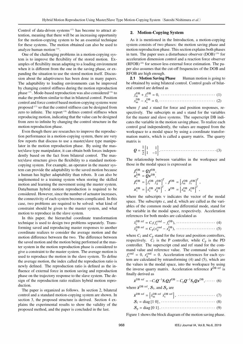
Figure 1 shows the block diagram of the motion saving phase.
968 IEEJ Journal IA, Vol.8, No.6, 2019
Hybrid Motion Reproduction Using Master/Slave Type Motion-Copying System(Satoshi Nishimura et al.)
Fig. 1. Block diagram of motion saving phase
Fig. 2. Block diagram of motion reproduction phase us-ing master and slave systems
2.2 Motion Reproduction Phase—Slave System—Once the motions are stored into a database, the data can
be used to reproduce the motion. The control structure ofthe reproduction phase is similar to that of the motion savingphase. In this phase, the vectors are defined as
f =[f DBm fs
]T, x =
[xDB
m xs
]T. · · · · · · · · · · · · · · · · · (10)
The acceleration reference for the slave system is calculatedin the same manner as
xref = −CfQ−1SfQ f −CpQ−1SpQx. · · · · · · · · · · · · · (11)
2.3 Motion Reproduction Phase—Master and SlaveSystems— There can be a lot of structures consideredwhen there are master and slave systems in the motion repro-duction phase. One of the structures is to use both responsesof stored master and slave systems in this phase. The struc-ture used in this paper as a conventional method is shown inFig. 2. The concept of this system is simple; stored motion ofthe master system is loaded at the slave system, while storedmotion of the slave system used in the master system.
The workspace variables used in the modal space are de-fined as
f1 =[f DBm fs
]T, x1 =
[xDB
m xs
]T, · · · · · · · · · · · · · · · (12)
f2 =[fm f DB
s
]T, x2 =
[xm xDB
s
]T, · · · · · · · · · · · · · · (13)
and the modal space variables are given as
fvi = Q fi,xvi = Qxi,
fvi =[fci fdi
]T , xvi = [xci xdi]T (i = 1, 2).
The acceleration references for this system is calculated as
xrefi = −CfQ−1SfQ fi − CpQ−1SpQxi (i = 1, 2).
· · · · · · · · · · · · · · · · · · · (14)
Acceleration reference matrices are xref1 =
[xref
m ◦], xref
2 =[◦ xref
s
]where ◦ is the variable not used in the control. The
important point is that there is no connection between themaster and slave systems in this structure.
3. Proposed Control Structure
In this section, the proposed method is introduced.3.1 Proposed Quarry Matrix As explained in the In-
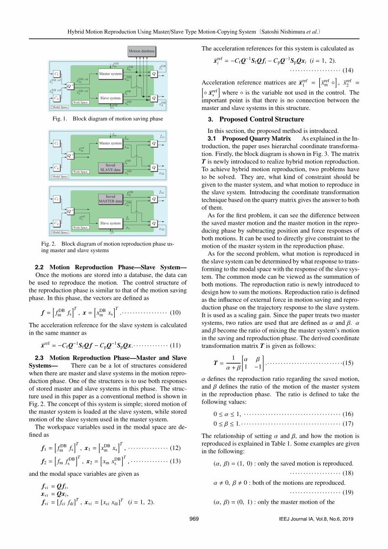
troduction, the paper uses hierarchal coordinate transforma-tion. Firstly, the block diagram is shown in Fig. 3. The matrixT is newly introduced to realize hybrid motion reproduction.To achieve hybrid motion reproduction, two problems haveto be solved. They are, what kind of constraint should begiven to the master system, and what motion to reproduce inthe slave system. Introducing the coordinate transformationtechnique based on the quarry matrix gives the answer to bothof them.
As for the first problem, it can see the difference betweenthe saved master motion and the master motion in the repro-ducing phase by subtracting position and force responses ofboth motions. It can be used to directly give constraint to themotion of the master system in the reproduction phase.
As for the second problem, what motion is reproduced inthe slave system can be determined by what response to trans-forming to the modal space with the response of the slave sys-tem. The common mode can be viewed as the summation ofboth motions. The reproduction ratio is newly introduced todesign how to sum the motions. Reproduction ratio is definedas the influence of external force in motion saving and repro-duction phase on the trajectory response to the slave system.It is used as a scaling gain. Since the paper treats two mastersystems, two ratios are used that are defined as α and β. αand β become the ratio of mixing the master system’s motionin the saving and reproduction phase. The derived coordinatetransformation matrix T is given as follows:
T =1
α + β
[α β1 −1
]. · · · · · · · · · · · · · · · · · · · · · · · · · · · ·(15)
α defines the reproduction ratio regarding the saved motion,and β defines the ratio of the motion of the master systemin the reproduction phase. The ratio is defined to take thefollowing values:
0 ≤ α ≤ 1, · · · · · · · · · · · · · · · · · · · · · · · · · · · · · · · · · · · · (16)
0 ≤ β ≤ 1. · · · · · · · · · · · · · · · · · · · · · · · · · · · · · · · · · · · · · (17)
The relationship of setting α and β, and how the motion isreproduced is explained in Table 1. Some examples are givenin the following:
(α, β) = (1, 0) : only the saved motion is reproduced.
· · · · · · · · · · · · · · · · · · · (18)
α � 0, β � 0 : both of the motions are reproduced.
· · · · · · · · · · · · · · · · · · · (19)
(α, β) = (0, 1) : only the master motion of the
969 IEEJ Journal IA, Vol.8, No.6, 2019
Hybrid Motion Reproduction Using Master/Slave Type Motion-Copying System(Satoshi Nishimura et al.)
Fig. 3. Block diagram of the proposed method
Table 1. Reproduction ratio
Condition Reproduction Ratio α and β
fully reproduced 1reproduced 0< α <1, 0< β <1
not reproduced 0
Table 2. Parameters for analysis
Parameter Description Value
Kp P gain in position control 10000.0Kd D gain in position control 200.0Cf P gain in force control 1.0
reproduction phase is reproduced. · · · · · · (20)
The acceleration reference of each system is obtained as
xrefm =
α
α + β(xDB
m − xm)Cpp −1
2
⎛⎜⎜⎜⎜⎝α f DBm + β fmα + β
+ fs
⎞⎟⎟⎟⎟⎠Cf
−1
2
⎛⎜⎜⎜⎜⎝αxDBm + βxm
α + β− xs
⎞⎟⎟⎟⎟⎠Cp · · · · · · · · · · · · · · · · · · · · (21)
xrefs = −
1
2
⎛⎜⎜⎜⎜⎝α f DBm + β fmα + β
+ fs
⎞⎟⎟⎟⎟⎠Cf −1
2
⎛⎜⎜⎜⎜⎝xs −αxDB
m + βxm
α + β
⎞⎟⎟⎟⎟⎠Cp,
· · · · · · · · · · · · · · · · · · · · · · · · (22)
where Cpp is the PD controller. Cpp is used to constrain thetrajectory of the master system in the motion reproductionphase.3.2 Connectivity Analysis The relationship between
the variables in the loading phase is analyzed in the follow-ing. The paper assumes three cases to analyze the connectiv-ity:
Case 1 : (α, β) = (1, 0), Cpp � 0,Case 2 : (α, β) = (1, 1), Cpp = 0,Case 3 : (α, β) = (0, 1), Cpp = 0.
The connectivity matrix is defined as
[xm
xs
]= H[− f DB
m − fm − fs xDBm
]T, · · · · · · · · · (23)
H =1
αA(2s2 +Cp) + 2βBs2
⎡⎢⎢⎢⎢⎢⎢⎢⎢⎢⎢⎢⎢⎢⎢⎢⎢⎢⎢⎢⎢⎢⎢⎢⎢⎢⎣
αCf BαCf (αA+βB)
α+β
βCf BβCf(αA+βB)
α+β(α+β)Cf B Cf(αA+βB)
α(CpA+(Cpp −Cp)2s2
)αCpA
⎤⎥⎥⎥⎥⎥⎥⎥⎥⎥⎥⎥⎥⎥⎥⎥⎥⎥⎥⎥⎥⎥⎥⎥⎥⎥⎦
T
, · · · · · (24)
A = s2 + Cpp, B = s2 + Cp.
The reason for the structure of H is because to analyzehow the trajectories of the systems in the motion reproduc-tion phase were affected by other variables.
The connectivity matrices of each case are calculated as
H1 =1
A(2s2 + Cp)
⎡⎢⎢⎢⎢⎢⎢⎢⎢⎢⎢⎢⎢⎣Cf B Cf A
0 0Cf B Cf A
CpA + (Cpp − Cp)2s2 CpA
⎤⎥⎥⎥⎥⎥⎥⎥⎥⎥⎥⎥⎥⎦
T
,
· · · · · · · · · · · · · · · · · · · · (25)
H2 =1
s2{(2s2 +Cp) + 2B}
⎡⎢⎢⎢⎢⎢⎢⎢⎢⎢⎢⎢⎢⎢⎢⎢⎢⎢⎢⎢⎢⎢⎢⎢⎢⎣
Cf BCf (s2 + B)
2
Cf BCf (s2 + B)
22Cf B Cf (s2 + B)Cps2 Cps2
⎤⎥⎥⎥⎥⎥⎥⎥⎥⎥⎥⎥⎥⎥⎥⎥⎥⎥⎥⎥⎥⎥⎥⎥⎥⎦
T
,
· · · · · · · · · · · · · · · · · · · · (26)
H3 =Cf
2s2
[0 1 1 00 1 1 0
], · · · · · · · · · · · · · · · · · · · · · · (27)
where the subscript shows the number of the case.3.3 Structural Analysis and Controller Design of Cpp
in Case 1 The second row of H1 becomes 0, which meansthe force applied to the master system in the motion repro-duction phase will not affect the trajectory of both systems.This is because the ratio β is 0 in this case.
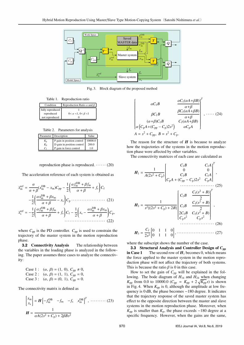
How to set the gain of Cpp will be explained in the fol-lowing. The bode diagram of H14 and H24 when changingKpp from 0.0 to 10000.0 (Cpp = Kpp + 2
√Kpps) is shown
in Fig. 4. When Kpp is 0, although the amplitude at low fre-quency is 0 dB, the phase becomes −180 degree. It indicatesthat the trajectory response of the saved master system haseffect to the opposite direction between the master and slavesystems in the motion reproduction phase. Moreover, whenKpp is smaller than Kp, the phase exceeds −180 degree at aspecific frequency. However, when the gains are the same,
970 IEEJ Journal IA, Vol.8, No.6, 2019
Hybrid Motion Reproduction Using Master/Slave Type Motion-Copying System(Satoshi Nishimura et al.)
Fig. 4. Bode plot of H14 in Case 1
the phase does not cross −180 degree. It indicates that Kpp
should be set as same as Kp. When setting Cpp = Cp, (25)becomes
H1 =1
2s2 + Cp
[Cf 0 Cf Cp
Cf 0 Cf Cp
]. · · · · · · · · · · · · · · (28)
The elements become the same as the motion-copying systemwith only a slave system.3.4 Structural Analysis of Case 2 In Case 2, all the
elements have frequency characteristics. H21 and H22 (H11
and H12) have the same element, meaning that the amount ofthe effect to the slave reproduced motion (constraint to themaster system) between the saved force and the force appliedat the master system in the motion reproduction phase is thesame. It can be said that the proposed structure covers frombilateral control to motion-copying system by designing αand β.
Comprehensive analysis is conducted in the following. Bymodifying (26) with remaining α and β as a variable and com-bining two equations into one, the following equation can beobtained:
xs =2AB(αA + βB)Cf{
αA(2s2 +Cp
)+ 2βBs2
} (2s2 + Cp
)( fcpT + fs)
+Cp
2s2 + CpxcpT, · · · · · · · · · · · · · · · · · · · · · · · · · · (29)
where
xcpT =αxDB
m + βxm
α + β, fcpT =
α f DBm + β fmα + β
.
xm is also included in the right-hand side of (29) to see theresponse of all the variables. It indicates that the trajectory ofthe slave system in the motion reproduction phase will trackthat of the mixed master systems, and the law of action andreaction between the slave force and the combined masterforces can be achieved.3.5 Structural Analysis of Case 3 First and fourth
rows of H3 becomes 0, indicating that the saved motion willappear in neither systems. Since the situation is the sameas bilateral control, whose connectivity matrix becomes thesame as the hybrid matrix, which is used in bilateral control.
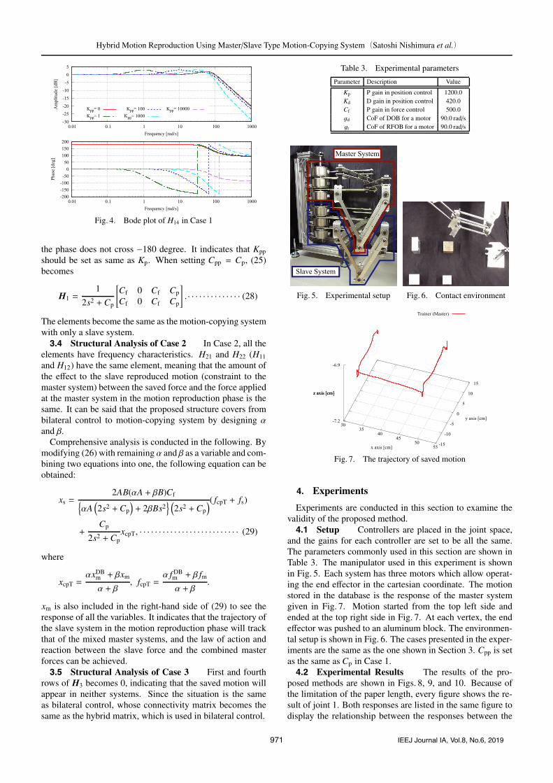
Table 3. Experimental parameters
Parameter Description Value
Kp P gain in position control 1200.0Kd D gain in position control 420.0Cf P gain in force control 500.0gd CoF of DOB for a motor 90.0 rad/sgr CoF of RFOB for a motor 90.0 rad/s
Fig. 5. Experimental setup Fig. 6. Contact environment
Fig. 7. The trajectory of saved motion
4. Experiments
Experiments are conducted in this section to examine thevalidity of the proposed method.4.1 Setup Controllers are placed in the joint space,
and the gains for each controller are set to be all the same.The parameters commonly used in this section are shown inTable 3. The manipulator used in this experiment is shownin Fig. 5. Each system has three motors which allow operat-ing the end effector in the cartesian coordinate. The motionstored in the database is the response of the master systemgiven in Fig. 7. Motion started from the top left side andended at the top right side in Fig. 7. At each vertex, the endeffector was pushed to an aluminum block. The environmen-tal setup is shown in Fig. 6. The cases presented in the exper-iments are the same as the one shown in Section 3. Cpp is setas the same as Cp in Case 1.4.2 Experimental Results The results of the pro-
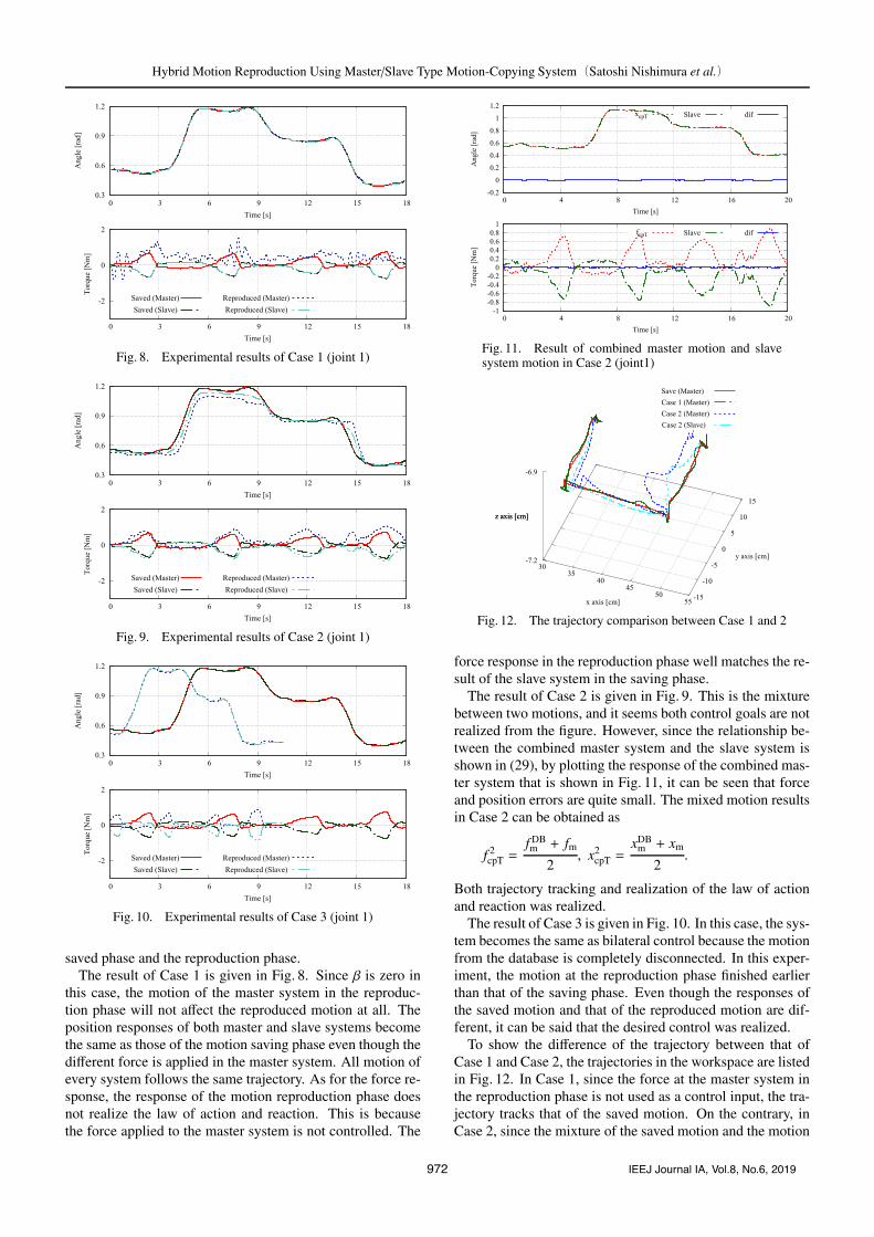
posed methods are shown in Figs. 8, 9, and 10. Because ofthe limitation of the paper length, every figure shows the re-sult of joint 1. Both responses are listed in the same figure todisplay the relationship between the responses between the
971 IEEJ Journal IA, Vol.8, No.6, 2019
Hybrid Motion Reproduction Using Master/Slave Type Motion-Copying System(Satoshi Nishimura et al.)
Fig. 8. Experimental results of Case 1 (joint 1)
Fig. 9. Experimental results of Case 2 (joint 1)
Fig. 10. Experimental results of Case 3 (joint 1)
saved phase and the reproduction phase.The result of Case 1 is given in Fig. 8. Since β is zero in
this case, the motion of the master system in the reproduc-tion phase will not affect the reproduced motion at all. Theposition responses of both master and slave systems becomethe same as those of the motion saving phase even though thedifferent force is applied in the master system. All motion ofevery system follows the same trajectory. As for the force re-sponse, the response of the motion reproduction phase doesnot realize the law of action and reaction. This is becausethe force applied to the master system is not controlled. The
Fig. 11. Result of combined master motion and slavesystem motion in Case 2 (joint1)
Fig. 12. The trajectory comparison between Case 1 and 2
force response in the reproduction phase well matches the re-sult of the slave system in the saving phase.
The result of Case 2 is given in Fig. 9. This is the mixturebetween two motions, and it seems both control goals are notrealized from the figure. However, since the relationship be-tween the combined master system and the slave system isshown in (29), by plotting the response of the combined mas-ter system that is shown in Fig. 11, it can be seen that forceand position errors are quite small. The mixed motion resultsin Case 2 can be obtained as
f 2cpT =
f DBm + fm
2, x2
cpT =xDB
m + xm
2.
Both trajectory tracking and realization of the law of actionand reaction was realized.
The result of Case 3 is given in Fig. 10. In this case, the sys-tem becomes the same as bilateral control because the motionfrom the database is completely disconnected. In this exper-iment, the motion at the reproduction phase finished earlierthan that of the saving phase. Even though the responses ofthe saved motion and that of the reproduced motion are dif-ferent, it can be said that the desired control was realized.
To show the difference of the trajectory between that ofCase 1 and Case 2, the trajectories in the workspace are listedin Fig. 12. In Case 1, since the force at the master system inthe reproduction phase is not used as a control input, the tra-jectory tracks that of the saved motion. On the contrary, inCase 2, since the mixture of the saved motion and the motion
972 IEEJ Journal IA, Vol.8, No.6, 2019
Hybrid Motion Reproduction Using Master/Slave Type Motion-Copying System(Satoshi Nishimura et al.)
Fig. 13. Result of Case 2-1
Fig. 14. Result of Case 2-2
Fig. 15. Result of Case 2-3
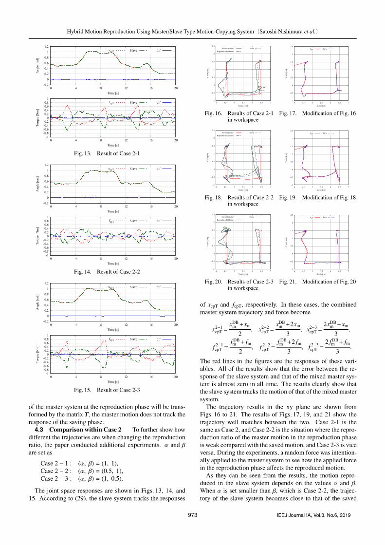
of the master system at the reproduction phase will be trans-formed by the matrix T, the master motion does not track theresponse of the saving phase.4.3 Comparison within Case 2 To further show how
different the trajectories are when changing the reproductionratio, the paper conducted additional experiments. α and βare set as
Case 2 − 1 : (α, β) = (1, 1),Case 2 − 2 : (α, β) = (0.5, 1),Case 2 − 3 : (α, β) = (1, 0.5).
The joint space responses are shown in Figs. 13, 14, and15. According to (29), the slave system tracks the responses
Fig. 16. Results of Case 2-1in workspace
Fig. 17. Modification of Fig. 16
Fig. 18. Results of Case 2-2in workspace
Fig. 19. Modification of Fig. 18
Fig. 20. Results of Case 2-3in workspace
Fig. 21. Modification of Fig. 20
of xcpT and fcpT, respectively. In these cases, the combinedmaster system trajectory and force become
x2−1cpT =
xDBm +xm
2, x2−2
cpT =xDB
m +2xm
3, x2−3
cpT =2xDB
m +xm
3,
f 2−1cpT =
f DBm + fm
2, f 2−2
cpT =f DBm +2 fm
3, f 2−3
cpT =2 f DB
m + fm3
.
The red lines in the figures are the responses of these vari-ables. All of the results show that the error between the re-sponse of the slave system and that of the mixed master sys-tem is almost zero in all time. The results clearly show thatthe slave system tracks the motion of that of the mixed mastersystem.
The trajectory results in the xy plane are shown fromFigs. 16 to 21. The results of Figs. 17, 19, and 21 show thetrajectory well matches between the two. Case 2-1 is thesame as Case 2, and Case 2-2 is the situation where the repro-duction ratio of the master motion in the reproduction phaseis weak compared with the saved motion, and Case 2-3 is viceversa. During the experiments, a random force was intention-ally applied to the master system to see how the applied forcein the reproduction phase affects the reproduced motion.
As they can be seen from the results, the motion repro-duced in the slave system depends on the values α and β.When α is set smaller than β, which is Case 2-2, the trajec-tory of the slave system becomes close to that of the saved
973 IEEJ Journal IA, Vol.8, No.6, 2019
Hybrid Motion Reproduction Using Master/Slave Type Motion-Copying System(Satoshi Nishimura et al.)
motion. On the other hand, the slave system tries to track themotion of the master motion in the reproducing phase morewhen α is set larger than β.
5. Conclusions
In this paper, the hybrid motion reproduction method usinga master/slave type motion-copying system was proposed.The setup used master-slave manipulators to obtain both ap-plied force from the person in the motion reproduction phaseand the force from the contact environment. It is essential toconsider the mixture between the motion of data and humanat the reproduction phase; therefore, the additional coordi-nate transformation matrix was proposed in this paper. Re-produced motion in the slave system was designed using theindex reproduction ratio. By setting the ratio as 0, motionfrom the person will not be reproduced in the slave system.The experimental results showed that the proposed methodworks under variable reproduction ratios.
One of the possible application of the proposed method isto use the system to motion training. Whether the qualityof motion training improves or not will be examined in thefuture.
AcknowledgmentThis work was partially supported by JSPS KAKENHI
Grant Number 18H03784.
References
( 1 ) R.C. Goertz: “Mechanical master-slave manipulator”, Nucleonics, Vol.12,No.11, pp.45–46 (1954)
( 2 ) P.F. Hokayem and M.W. Spong: “Bilateral teleoperation: An historical sur-vey”, Automatica, Vol.42, No.12, pp.2035–2057 (2006)
( 3 ) L. Eusebi and C. Melchiorri: “Force reflecting telemanipulators with time-delay: Stability analysis and control design”, IEEE Transactions on Roboticsand Automation, Vol.14, No.4, pp.635–640 (1998)
( 4 ) F. Mobasser, K. Hashtrudi-Zaad, and S. Salcudean: “Impedance reflectingrate mode teleoperation”, in Proceedings of the IEEE International Confer-ence on Robotics and Automation, ICRA, Vol.3, pp.3296–3302 (2003)
( 5 ) M. Tajiri, P. Lopez, and Y. Fujimoto: “Design of two-channel bilateral con-trol systems by a transfer-function-based approach”, IEEE Transactions onIndustrial Electronics, Vol.65, No.7, pp.5655–5664 (2018)
( 6 ) R. Kubo, N. Iiyama, K. Natori, K. Ohnishi, and H. Furukawa: “Performanceanalysis of a three-channel control architecture for bilateral teleoperationwith time delay”, IEEJ Journal of Industry Applications, Vol.127, No.12,pp.1224–1230 (2007)
( 7 ) D. Lawrence: “Stability and transparency in bilateral teleoperation”, IEEETransactions on Robotics and Automation, Vol.9, No.5, pp.624–637 (1993)
( 8 ) S. Katsura, W. Iida, and K. Ohnishi: “Medical mechatronics: An applicationto haptic forceps”, Annual Reviews in Control, Vol.29, No.2, pp.237–245(2005)
( 9 ) Y. Kuniyoshi, M. Inaba, and H. Inoue: “Learning by watching: extractingreusable task knowledge from visual observation of human performance”,IEEE Journal of Robotics and Automation, Vol.10, No.6, pp.799–822 (1994)
(10) Y. Yokokura, S. Katsura, and K. Ohishi: “Stability analysis and experimen-tal validation of a motion-copying system”, IEEE Transactions on IndustrialElectronics, Vol.56, No.10, pp.3906–3913 (2009)
(11) C. Fitzgerald: “Developing baxter”, in Proceedings of the IEEE Conferenceon Technologies for Practical Robot Applications, TePRA, pp.1–6 (2013)
(12) W. Chung, C. Rhee, Y. Shim, H. Lee, and S. Park: “Door-opening controlof a service robot using the multifingered robot hand”, IEEE Transactions onIndustrial Electronics, Vol.56, No.10, pp.3975–3984 (2009)
(13) Y. Jiang, Y. Zhu, K. Yang, C. Hu, and D. Yu: “A data-driven iterative de-coupling feedforward control strategy with application to an ultraprecisionmotion stage”, IEEE Transactions on Industrial Electronics, Vol.62, No.1,pp.620–627 (2015)
(14) H. Kuwahara, T. Shimono, H. Tanaka, D. Yashiro, and K. Ohnishi: “Ab-straction of action components unconstrained by alignment of haptic sensingpoints”, IEEE Transactions on Industrial Electronics, Vol.58, No.8, pp.3196–3204 (2011)
(15) T. Nozaki, T. Mizoguchi, and K. Ohnishi: “Motion-copying system with vari-able impedance based on scaled bilateral control in one-degree-of-freedomrobot”, Vol.3, No.1, pp.1–9 (2014)
(16) A. Matsui and S. Katsura: “Motion-copying system using modal informationfor motion reproduction”, in Proceedings of the Annual Conference of IEEEIndustrial Electronics Society, IECON, pp.6132–6137 (2013)
(17) K. Miura, A. Matsui, and S. Katsura: “Synthesis of motion-reproductionsystems based on motion-copying system considering control stiffness”,IEEE/ASME Transactions on Mechatronics, Vol.21, No.2, pp.1015–1023(2016)
(18) S. Katsura: “Real-world haptics for supporting motion training”, in Proceed-ings of the IEEJ Annual Meeting, pp.1–4 (2014)
(19) K. Ohishi, K. Ohnishi, and K. Miyachi: “Torque-speed regulation of DCmotor based on load torque estimation method”, in Proceedings of the IEEJInternational Power Electronics Conference, IPEC, pp.1209–1218 (1983)
(20) T. Murakami, F. Yu, and K. Ohnishi: “Torque sensorless control inmultidegree-of-freedom manipulator”, IEEE Transactions on IndustrialElectronics, Vol.40, No.2, pp.259–265 (1993)
Satoshi Nishimura (Member) received his B.E. degree in systemdesign engineering, M.E. and Ph.D. degrees in in-tegrated design engineering from Keio University,Yokohama, Japan, in 2013, 2014, and 2017, respec-tively. His research interests include real–world hap-tics and motion control. He is a Member of IEEJ, aswell as IEEE.
Seiichiro Katsura (Senior Member) received the B.E. degree in sys-tem design engineering and the M.E. and Ph.D. de-grees in integrated design engineering from Keio Uni-versity, Yokohama, Japan, in 2001, 2002 and 2004,respectively. From 2003 to 2005, he was a ResearchFellow of the Japan Society for the Promotion of Sci-ence (JSPS). From 2005 to 2008, he worked at Na-gaoka University of Technology, Nagaoka, Niigata,Japan. Since 2008, he has been at Department ofSystem Design Engineering, Keio University, Yoko-
hama, Japan. Currently he is working as Professor. In 2017, he was a Vis-iting Researcher with the Laboratory for Machine Tools and Production En-gineering (WZL) of RWTH Aachen University, Aachen, Germany. His re-search interests include applied abstraction, human support, data robotics,wave system, systems energy conversion, and electromechanical integrationsystems. Prof. Katsura serves as an Associate Editor of the IEEE Transac-tions on Industrial Electronics and Technical Editor of IEEE/ASME Trans-actions on Mechatronics. He was the recipient of The Institute of ElectricalEngineers of Japan (IEEJ) Distinguished Paper Awards in 2003 and 2017,IEEE Industrial Electronics Society Best Conference Paper Award in 2012,and JSPS Prize in 2016.
974 IEEJ Journal IA, Vol.8, No.6, 2019