Embed Size (px)
Citation preview

— HVDC LightIt’s time to connect

2 H V D C LI G HT IT´S T I M E TO CO N N EC T
— HVDC (high-voltage direct current) is a highly efficient alternative for transmitting large amounts of electricity over long distances and for special purpose applications. As a key enabler in the future energy system based on renewables, HVDC is truly shaping the grid of the future.

3
— Table of contents
004 – 009 Introducing HVDC
010– 019 This is ABB HVDC Light
020 – 029 Applications
030 – 049 HVDC Light technology
050 – 053 Lifecycle Services for HVDC
054 HVDC digital models
055 References
056 – 060 Index
TA B L E O F CO NTENTS

4 H V D C LI G HT IT´S T I M E TO CO N N EC T
1.1 This is HVDCHigh-voltage direct current (HVDC) was first de-veloped during the 1930s by ASEA, the Swedish electrical conglomerate and one of the founders of ABB. For many years HVDC engineers looked for a reliable converter technology that could ef-fectively switch AC electricity produced at the point of generation into DC electricity for trans-mission, and then convert it back to AC again at the other end of the line so it could run motors, lights, etc. By the early 1950s research into mer-cury-arc technology, led by ASEA engineer and HVDC pioneer Uno Lamm, had made such prog-ress that ASEA could build the world’s first com-mercial HVDC power link between the Island of Gotland and the Swedish mainland. Since then, HVDC transmission systems have been installed in many parts of the world. This transmission is a safe and efficient technology designed to deliver large amounts of electricity over long distances.
1.2 The benefits of HVDC HVDC systems can transmit more electrical power over longer distances than a similar AC transmission system, which means fewer trans-mission lines are needed, saving both money and land. In addition to significantly lowering electri-cal losses over long distances, HVDC technology is easily controlled, and can stabilize and inter-connect AC power networks that are otherwise incompatible. The HVDC market is growing rapidly and has be-come an important part of many transmission networks, not least because it can connect re-mote sources of electrical power – often emis-sions-free renewable sources like hydro or wind generation – to load centres where it is needed, hundreds or even thousands of kilometres away. Once installed, HVDC transmission systems often form the backbone of an electric power system, combining high reliability with a long, useful life. Their core component is the power converter, which serves as the interface with the AC trans-mission system. The conversion from AC to DC, and vice versa, is achieved by controllable elec-tronic switches (called valves).
1.3 The development of HVDC technologyToday there are two main technologies. HVDC LCC, by ABB called HVDC Classic, the first devel-
—Introducing HVDC
oped technology. LCC is used primarily for Con-necting remote generation over long distances, Grid interconnection and DC links in AC grid, over-land or subsea, where conventional AC methods cannot be used. Today there are more than 170 HVDC installations in all parts of the world. A clas-sic HVDC transmission typically has a power rating of more than 100 megawatts (MW) and many are in the 1000 – 12,000 MW range. They use overhead lines, cables, or a combination of cables and lines.
The second one is HVDC Light, also known as HVDC VSC, developed by ABB and launched in 1997, is an adaptation of HVDC classic used to transmit electricity i using environmentally friendly cables, overhead lines or a mix of cables and overhead lines. It can be used for: Connecting remote generation, Grid interconnections, Off-shore wind connections, DC links in AC grids, Power from shore, City centre infeed and Connect-ing remote loads. With ABB HVDC Classic and Light, it is possible to transmit power in both di-rections and to support existing AC grids in order to increase robustness, stability and controllabil-

5

6 H V D C LI G HT IT´S T I M E TO CO N N EC T
—01
—02
—01 The Gotland 1 valve hall from the 1950’s.—02 Valve hall 2014
ity. 1.4 The development of HVDC Light technologyThe HVDC Light technology, based on voltage source converters (VSC), has evolved since its in-troduction. When the technology was introduced it was based on a two-level converter and had the same basic functionality as today, but with rela-tively high losses. The focus of development over the years has been to maintain functionality, im-prove performance and reduce losses in order to make it more economical.
The two-level converter valve together with cus-tom designed series-connected press-pack insu-lated-gate bipolar transistors (produced by ABB) have been the cornerstone of HVDC Light since the first generation. The technical developments have made it possible to handle higher DC volt-ages applying a cascaded two-level converter (CTL) and multi –level converters (MMC). Technol-ogy modules developed and refined during the last 15 years have made it possible to create con-verters with increased power, technical perfor-mance and lower losses, while retaining opera-tional functionality and use experience from the start of the VSC era.
1.5 Market outlookEnergy infrastructure is an essential building block of our society. Ambitious climate change goals, strong global demand for electricity and aggressive economic growth targets will not be achievable without a major shift in the way infra-structure is developed.
Integrated and reliable transmission networks are a crucial prerequisite for developing integrated energy markets, enhancing security of supply, en-abling the integration of renewable energy
sources, and increasing energy efficiency.The VSC technology market has grown rapidly in recent years to fulfill these goals. Thanks to its technical properties, it has been selected for a number of transmission projects aimed at inter-connecting European energy markets by means of undergrounding, integrating remote renewable energy sources such as wind farms at sea, and in applications like power from shore, which strives to further decarbonize our environment.
As transmission capacity has been increased and electrical losses reduced, HVDC Light technology has the right properties to become the natural choice for transmission projects. VSC technology is a prerequisite to solving many of the energy system challenges of the future. It has the right properties to support:
- Further integrating remote renewables such as hydro, wind and solar generation into the energy system
- Stabilizing transmission grids with large shares of volatile generation in the power net-works
- Facilitating energy sharing and trading by in-terconnecting energy markets
- Overcoming limits in new right-of-way by land and sea cable transmission and AC to DC con-version in existing overhead line corridors
- Enabling remote load connections such as off-shore platforms and remote loads
- Feeding electricity into densely populated ur-ban centers
- Constituting the backbone of a DC grid to transmit bulk power through congested areas
- In the following section, the functionality of HVDC Light will be demonstrated in more de-tail.

7
1.6 How can HVDC support renewable energy systems? Alternatives to burning fossil fuels for electricity, including hydro, wind and solar generation, are often located in remote, hostile locations and need robust electrical transmission systems to ensure high availability, minimal maintenance and of course, low losses. HVDC transmission systems offer the best technical and economical long dis-tance transmission solutions, integrating volatile renewable generation, and stabilizing power net-works.
1.7 What else can HVDC do? There are numerous ways to use HVDC transmis-sion. For example, HVDC systems deliver electri-cal power to remote loads such as offshore plat-forms, and remote loads. In addition to reliably delivering electricity generated from mountain-tops, deserts and seas across vast distances with low losses, HVDC systems can stabilize problems in AC networks and improve grid performance in the event of power disturbances. HVDC systems are ideal for feeding electricity into densely populated urban centers, and for interconnecting separate power networks to facilitate energy sharing and trading.
1.8 Lifetime service support for HVDC installa-tionsHigh Voltage Direct Current (HVDC) Life Cycle Services from ABB including HVDC Care, HVDC Upgrades, and Long Term Service Agreements (LTSA) are an insurance policy protecting the pro-duction uptime, availability and reliability of HVDC installations. ABB provides total assurance in all phases of the installation lifecycle with HVDC Care service products like 24/7 phone sup-port, 24/7 remote access, on-site corrective main-tenance, preventative maintenance, spare parts management, as well as partial and complete up-grades. Total cost of ownership throughout an HVDC system lifecycle relates to the system’s ca-pacity and performance requirements (service level). ABB is committed to delivering customer satisfaction by providing timely, responsive ser-vice with a passion for excellence and reliability. ABB Ability is a portfolio of our latest digital solu-tions and platforms designed to help HVDC cus-tomers take full advantage of digitalization in their installations.
During the warranty period of an HVDC system delivery contract we work with customers to min-imize future outages and unnecessary stoppages. With a post-warranty service contract, an ABB HVDC support team proactively schedules pre-ventive support activities and also handles any rapid response issues that may arise. In addition, Health and Safety is a top ABB priority that en-sures HVDC support services deliver safe, reliable high-performance power transmission systems.
3,5%
3,0%
2,5%
2,0%
1,5%
1,0%
0,5%
0,0%
1995 2000 2005 2010 2015
HVDC LCC
HVDC VSC
2020
—03 Losses for HVDC Light have decreased since it first was introduced in 1997
INTR O D U CIN G H V D C

8 H V D C LI G HT IT´S T I M E TO CO N N EC T

9

10 H V D C LI G HT IT´S T I M E TO CO N N EC T
There are a number of criteria which help to de-cide which technology is best suited for a particu-lar customer application, including investment costs (capital expenditure), system losses, sys-tem availability, power and voltage levels, means of transmission, availability of land and AC net-work support.
In the following sections it will be explained what advantages customers can obtain from the unique properties of HVDC Light®.
2.1 Independent power transfer and power quality control The HVDC Light system allows fully independent control of both the active and the reactive power flow within the operating range of the HVDC Light system. The active power can be continu-ously controlled from full power export to full power import. Normally each station controls its reactive power flow independently of the other station. However, the flow of active power to the DC network must be balanced, which means that the active power leaving the DC network must be equal to the active power coming into the DC net-work, minus the losses in the HVDC Light system. A difference in power would imply that the DC voltage in the system would rapidly increase or decrease, as the DC capacitors change their volt-age with increased or decreased charge. To attain this power balance, one of the stations controls the DC voltage. This means that the other station can arbitrarily adjust the transmitted power within the power capability limits of the HVDC Light® system, whereby the station that controls the DC voltage will adjust its power to ensure that the balance (i.e. constant DC voltage) is main-tained. The balance is attained without telecom-munication between the stations, but simply on the measurement of the DC voltage.
2.2 Absolute and predictable power transfer and voltage controlThe active power flow can be determined either by means of an active power order or by means of frequency control in the connected AC network. The converter stations can be set to generate re-active power through a reactive power order, or to maintain a desired voltage level in the con-nected AC network. The converter’s internal con-
—This is HVDC Light
trol loop is active and reactive current, controlled through measurement of the current in the con-verter inductor and using orders from settings of active and reactive power which an operator can make. In an AC network, the voltage at a certain point can be increased or reduced through the generation or consumption of reactive power. This means that HVDC Light can control the AC voltage independently in each station.
2.3 Low power operation Unlike HVDC Classic converters, the HVDC Light converter can operate at very low power, or even zero power. The active and reactive powers are controlled independently, and at zero active power the full range of reactive power can be uti-lized. In this way the HVDC Light converter can operate as a SVC, Static VAr Compensator.
2.4 Power reversal An HVDC Light transmission system can transmit active power in either of two directions with the same control setup and with the same main cir-cuit configuration. This means that an active power transfer can be quickly reversed without any change of control mode, and without any fil-ter switching or converter blocking. The power re-versal is obtained by changing the direction of the DC current and not by changing the polarity of the DC voltage as for HVDC Classic. The speed of the reversal is determined by the network. The converter could reverse to full power in millisec-onds if needed. The reactive power controller op-erates simultaneously and independently in order to keep the ordered reactive power exchange un-affected during power reversal.
2.5 Reduced power losses in connected AC systems By controlling the grid voltage level, HVDC Light can reduce losses in the connected grid. Trans-mission line ohmic losses can be reduced. Signifi-cant loss reductions can be obtained in each of the connected networks.
2.6 Increased transfer capacity in the existing system Voltage increaseThe rapid and accurate voltage control capability of the HVDC Light converter makes it possible to operate the grid closer to the upper limit. Tran-

11
—01 HVDC Light station
sient overvoltages would be counteracted by the rapid reactive power response. The higher volt-age level would allow more power to be trans-ferred through the AC lines without exceeding the current limits.
Stability marginsLimiting factors for power transfer in the trans-mission grid also include voltage stability. If such grid conditions occur where the grid is exposed to an imminent voltage collapse, HVDC Light can support the grid with the necessary reactive power. The grid operator can allow a higher trans-mission in the grid if the amount of reactive power support that the HVDC Light converter can provide is known. The transfer increase in the grid is in many cases larger than the installed MVA capacity of the HVDC Light converter.
2.7 Powerful damping control using P and Q simultaneouslyAs well as voltage stability, rotor angle stability is a limiting factor for power transfer in a transmis-sion grid. HVDC Light is a powerful tool for damp-ing angle (electromechanical) oscillation. The electromechanical oscillations can be rather com-plex with many modes and many constituent
parts. It is therefore not always possible to find robust damping algorithms that do not excite other modes when damping the first ones. Many control methods that influence the transmission capacity can experience difficulties in these com-plex situations. Modulating shaft power to gener-ators, switching load demand on and off, or using an HVDC Light system connected to an asynchro-nous grid are methods that can then be consid-ered. The advantage of these methods is they ac-tually take away or inject energy to damp the oscillations.
HVDC Light is able to do this in several ways: - by modulating the active power flow and
keeping the voltage as stable as possible - by keeping the active power constant and
modulating the reactive power to achieve damping (SVC-type damping)
Line current, power flow or local frequency may be used as indicators, but direct measurement of the voltage angle by means of Phasor measure-ments can also be used.
2.8 Fast restoration after blackouts HVDC Light can aid grid restoration in the event
TH IS IS H V D C L I G HT

12 H V D C LI G HT IT´S T I M E TO CO N N EC T
of power disruptions, when voltage and fre-quency support are much needed. This was first proven during the August 2003 blackout in the Northeastern U.S by the excellent performance of the Cross Sound cable link that interconnects Connecticut and Long Island. In the event of a power disruption, a black-start capability can be implemented in HVDC Light systems. This can help an HVDC Light operator speed up grid resto-ration, because the lack of energy (typically in the first 6-24 hours) may initiate considerably higher prices for energy. This black-start facility is imple-mented and full scale tested in many HVDC Light project such as ÅLink and Skagerrak 4 project.
2.9 Islanded operation The HVDC Light converter station normally fol-lows the AC voltage of the connected grid. The voltage magnitude and frequency are determined by the control systems of the generating stations. In the event of a voltage collapse or “black-out,” the HVDC Light converter can instantaneously switch over to its own internal voltage and fre-quency reference and disconnect itself from the grid. The converter can then operate as an idling “static” generator, ready to be connected to a “black” network to provide the first electricity to important loads. The only precondition is that the converter at the other end of the DC cable is unaf-fected by the black-out.
2.10 Flexibility in designThe HVDC Light station consists of three parts:
- The DC yard, with DC cable or DC overhead line interface
- The converter of modular design, with the IGBT/BIGT valves and the converter reactors
- The grid interface, with power transformer and switches
The different parts are interconnected with busworks or HV cables, which make it easy to
separate the parts physically, so as to fit them into available sites.
HVDC Light can be implemented in back-to-back stations, as well as transmission systems with DC cables or overhead lines.
2.11 Undergrounding HVDC Light is well suited to be used with HVDC cables with XLPE insulation for DC power trans-mission that are well suited for undergrounding. The cables are buried all the way into the DC part of each converter building. When the landscape has been restored after the cable laying, the transmission route quickly becomes invisible.
2.12 Magnetic fieldsThe two HVDC cables can normally be laid close together. As they carry the same current in oppo-site directions, the magnetic fields from the ca-bles more or less cancel each other out. The resid-ual magnetic field is extremely low, comparable to the level of the earth’s magnetic field. Mag-netic fields from HVDC cables are static fields, which do not cause any induction effects, as op-posed to the fields from AC cables and lines.
The electromagnetic field around an HVDC Light converter installation is possible to keep on a quite low level if required. The active parts (Valves) of the station is enclosed. The shielding is needed to minimize emissions in the radio fre-quency range, i.e. radio interference. The emis-sion source is that in HVDC Light converter high currents are switched, giving high internal current derivatives. Such switchings generate frequen-cies that might cause radio interference if not properly controlled and shielded. Considering these conditions, the overall and detailed design has been aimed at ensuring proper mitigation of radio interference and corresponding fields to specified levels. The electromagnetic field levels
—01 Cable laying
—01
13
around the installation are therefore below the values stipulated in Client Specification or rele-vant standards for human exposure. The electro-magnetic emission can be verified through mea-surements. The HVDC Light converter installation is connected to the AC power grid/system through AC overhead lines or AC cables. Normally, current harmonics from the converter are small and no harmonic filters are needed on the output lines.
2.13 Low environmental impactEnvironmental considerations have a strong influ-ence in the design, the choice of material and the manufacturing processes. IF XLPE HVDC cable will be used for the transmission link it will mini-mize the visual impact compared to overhead lines. The fact that no electric or magnetic clear-ance from the HVDC cables is needed, and that the converter stations might be enclosed in a building, makes the impact of the transmission system on the environment very low. The building can be designed to resemble other buildings in the neighbourhood.
2.14 Indoor designFor an indoor design tall steel supporting struc-tures are not needed and to facilitate mainte-nance and to improve personal safety, converter reactors and DC yard equipment are mounted di-rectly on low foundations/supports and kept within a simple warehouse-style building with lockable gates and doors. The building will keep high-frequency emissions and acoustic noise low and protect the equipment from adverse weather.
2.15 Time scheduleThe converter valves and associated control and cooling systems are factory assembled in trans-portable modules. This ensures rapid installation and on-site testing of the core systems.
The building is made up of standardized parts, which are shipped to the site and quickly assem-bled. A typical delivery time from order to hand-over for operation depends of course on local conditions for converter sites and cable route.
2.16 Comparison of HVDC and AC cable systems HVDC cable system
- No limit on cable length - No intermediate station needed - No increase of capacitance in the AC network - (avoids low-order resonances) - Lower losses
AC cable system - Cable capacitance limits the practical cable
length - Reactive compensation is needed in most
cases
2.17 Comparison of ABB HVDC Light and ABB HVDC ClassicABB HVDC Light (power up to 3,000 MW)
- Each terminal is an HVDC converter with in-creased controllability
- Suitable for cable connections, overhead lines and Back to Back
- Advanced system features - Reduced Footprint, around 30% of corre-
sponding size of a HVDC Classic converter - Short delivery time
HVDC Classic (power up to 12,000 MW) - Most economical way to transmit High power
over long distances - Long submarine cable connections possible - Around three times more power in a right-of-
way than overhead AC
—02 HVDC Light (power from 50 – 1,800 MW)—03 HVDC Classic (power up to 8,000 MW)
—02
—03

14 H V D C LI G HT IT´S T I M E TO CO N N EC T
HVDC LightIGBT/BIGT used as active component in valves
- Multi-chip design - Forward blocking only - Current limiting characteristics - Gate turn-off and fully controllable; forced
commutation - High-speed device
The pulse width controls both active and reactive power
- The IGBT/BIGT can be switched off with a con-trol signal; fully controllable
-400
-200
0
200
400
(kV
)
-400
-200
0
200
400
(kV
)
-400
-200
0
200
400
(kV
)
0 0.01 0.02 0.03 0.04 0.05 0.06 0.07 0.08 0.09 0.1time (seconds)
0 0.01 0.02 0.03 0.04 0.05 0.06 0.07 0.08 0.09 0.1
udp,n (voltage on positive/negative DC poles)
0 0.01 0.02 0.03 0.04 0.05 0.06 0.07 0.08 0.09 0.1
ua,b,c (voltage at converter bus)
upcca,b,c (voltage at point of common coupling)-400
-200
0
200
400
(kV
)
-400
-200
0
200
400
(kV
)
-400
-200
0
200
400
(kV
)
0 0.01 0.02 0.03 0.04 0.05 0.06 0.07 0.08 0.09 0.1time (seconds)
0 0.01 0.02 0.03 0.04 0.05 0.06 0.07 0.08 0.09 0.1
udp,n (voltage on positive/negative DC poles)
0 0.01 0.02 0.03 0.04 0.05 0.06 0.07 0.08 0.09 0.1
ua,b,c (voltage at converter bus)
upcca,b,c (voltage at point of common coupling)
Phasereactor
Harmonic filter
Valve
IGBT & diode
DC
Transformer
DC
DC
1.25 1 0.75 0.5 0.25 0 0.25 0.5 0.75 1 1.25
1.25
1
0.75
0.5
0.25
0.25
0.5
0.75
1
1.25
P-Q Diagram (whole voltage range)
Reactive Power (P.U.)
Act
ive
Po
wer
(P.
U.)
1.25
1.25−
P φ( )
1.251.25− Q φ( )
—01 AC and DC voltage characteristics—02 Simplified single-line diagram for HVDC Light—03 An HVDC Light transmission system can control both active and reactive power.
—01
—02
—03

15
HVDC Classic - Thyristor used as active component in valves - Single silicon wafer - Both forward and reverse blocking capability - Very high surge current capability - No gate turn-off; line commutated
Phase angle control - The thyristor cannot be switched off with a
control signal - It automatically ceases to conduct when the
voltage reverses - Line commutated, 50/60 Hz
—04 Simplified single-line diagram for HVDC Classic—05 Reactive power exchange for HVDC Classic.
—04
—05
Y
Y
YAC bus
Converter stationTransmissionline or cable
Converterstation
Shuntcapacitors
or otherreactive
equipment
AC filters
Converter
Smoothingreactor
DC filter
Telecommunication
Controlsystem
Shuntbanks
Harmonicfilters
Q
Unbalance1, P
O
TH IS IS H V D C L I G HT

16 H V D C LI G HT IT´S T I M E TO CO N N EC T
2.18 Operating configurationsHVDC/HVDC Light® converters can form a trans-mission system in various operating configura-tions. The most common operating configura-tions are briefly described below highlighting the main advantages/disadvantages:
Symmetric monopole
Advantages: - No infeed of fault currents from the AC grid at
DC pole ground faults - Transformers are not exposed to DC stresses - No DC ground current
Disadvantages: - Limited redundancy for full power compared
to a bipolar configuration - Requires two fully insulated DC conductors
Asymmetric monopole, Metallic return
Advantages: - The metallic return DC conductor does not re-
quire full insulation - Allows for expansion to a bipolar system at a
later stage - No DC ground current
Disadvantages: - Limited redundancy for full power compared
to a bipolar configuration - Transformers must be designed for DC
stresses
Assymetric monopole, ground return
Advantages: - Cost and losses are minimized due to the sin-
gle DC conductor - Allows for expansion to a bipolar system at a
later stage
Disadvantages: - Requires permission for continuous operation
with DC ground current - Requires permission for electrodes (including
environmental effects) - Infeed of fault current from the AC grid at DC
pole ground faults - Limited redundancy compared to a bipolar
configuration - Transformers must be designed for DC
stresses
Bipole, Ground electrodes
Advantages: - Redundancy for 50 percent of the total rating
Disadvantages: - More costly for the same rating compared to
monopolar configurations - Requires permission for temporary operation
with DC ground current - Requires permission for electrodes (including
environmental effects) - Infeed of fault current from the AC grid at DC
pole-ground faults - Transformers must be designed for DC
stresses
Bipole, Metallic return
Advantages: - Redundancy for 50 percent of the total rating
Disadvantages: - More costly for the same rating compared to
monopolar configurations - Requires low-voltage insulated DC neutral
conductor - Transformers must be designed for DC
stresses
Multi-terminal
Multi-terminal systems can be constructed based on all described configurations. A three-terminal example, based on symmetric monopoles, can be seen above.

17
2.18.1 Back-to-backA Light HVDC back-to-back station consists two converters located in the same building.
An HVDC back-to-back station can be used to cre-ate an asynchronous interconnection between two AC networks. There are several back-to-back stations in operation in the world. In these instal-lations both the rectifier and the inverter are lo-cated in the same station and are normally used in order to create an asynchronous interconnec-tion between two AC networks, which could have the same or different frequencies. Another bene-fit is using a Back to Back for splitting up a too strong network to reduce short circuit current.
The direct voltage level can be selected without consideration of the optimum values for an over-head line and a cable, and is therefore normally quite low, 150 kilovolts (kV) or lower. The only ma-jor equipment on the DC side is a smoothing reac-tor.
2.18.2 HVDC gridThe growing need to integrate and transmit large amounts of remote renewable energy and to in-terconnect different power markets is a driving force for growth of HVDC transmission systems. With the increasing number of DC systems being installed, a larger overall DC transmission system – an HVDC grid – could emerge. HVDC grids is an important step towards an energy system based on renewable energy sources. Such a DC grid could act as an overlay or backbone system inte-grated with the existing AC grid, where several DC terminals are serving multiple purposes.
2.18.3 HVDC Hybrid breakerThe hybrid HVDC breaker has been a vital missing link in the development of DC transmission grids. In 2012 finally the breakthrough came and ABB presented the first HVDC breaker. It will help ful-fill the grid vision and also enable combined AC and DC multi-grid systems.
The hybrid HVDC beaker has a built-in monitor-ing, control and protection system based on stan-dard HVDC Light MACH technology. To ensure proper operation, internal currents and other sig-nals are monitored and used to operate the breaker in both normal and malfunctioning condi-tions.
Key characteristics of the hybrid HVDC breaker are low losses and ultra-fast operation within a few milliseconds - 30 times faster than the blink of an eye. It has been designed to handle power flows equivalent to thousands of megawatts - enough to power cities. The hybrid HVDC breaker is designed for the today’s standard ratings of HVDC systems, up to 525 kV and 3000 A, and the solution is scalable to lower and higher voltages. The hybrid HVDC Breaker can be designed to in-terrupt up to 25 kA fault current.
2.19 Drivers for choosing HVDC Light
AC network support - Active and reactive power independently and
rapidly - controlled - Operation down to short-circuit ratios of zero - Loop flows of power can be avoided - Black start is possible - Stabilization of connected AC grids - Share spinning reserve between areas - Continuously variable power from full power
in one - direction to full power in reverse - Emergency power support - Increase power in parallel AC lines - No commutation failures - Multi-terminal system simple - No minimum power - can operate down to
zero power - Additional reactive shunt compensation is not
required (only small harmonic filters may in some cases be needed)
- The HVDC Light® stations can be operated as
—01 Back-to-back stations connect asynchro-nous networks.
TH IS IS H V D C L I G HT

18 H V D C LI G HT IT´S T I M E TO CO N N EC T
STATCOMs, even if they are not connected to a DC line. It is possible to build one or two sta-tions for voltage stabilization and connect them later with cables to create an intercon-nection.
Undergrounding by XLPE HVDC cables - No visible impact by overhead lines which can
make it easier to get permission to install - Only static electromagnetic fields - No audible noise
Required site area for converters - Minimal impact on environment - More compact site - Less space per MW required than for conven-
tional HVDC - Indoor design possible - less visible - lower noise
Environmentally friendly - Audible sound reduced by indoor design - Converter hall and service building possible to
design to local requirements - Converter building kept under 20 m - Bipolar operation – no need for ground elec-
trodes if neutral line is used
Energy trading - Fast and accurate power control - No filter switching at power change - Smooth power reversal (step less power trans-
fer around zero MW)

19

20 H V D C LI G HT IT´S T I M E TO CO N N EC T
With the features presented in the previous chap-ter, HVDC Light is the preferred system for use in a variety of transmission applications, using sub-marine cables, land cables, overhead lines or con-nected back-to-back.
3.1 Connecting remote generationThe world’s demand for energy continues to grow at a rapid pace. Today, energy is mostly generated by burning fossil fuels, but in addition to the seri-ous impact this has on the environment, fossil fuel resources are finite. As they become harder to find and harvest, sustainable emissions-free renewable energy generation will undoubtedly come to play an important role in the energy busi-ness. Getting the power to consumers is an addi-tional challenge, because the best generating sites are often in remote areas, so electricity must often cross vast distances to get to where it is needed most. HVDC is the most reliable and ef-ficient way of getting it there, and HVDC trans-mission systems are already delivering electricity to millions of consumers every day. For example, a 2,000-km long HVDC transmission line at 800 kV loses about 5 percent of its power to heat, while the power losses in an AC line of similar voltage are around twice as high. HVDC transmission lines also have negligible electromagnetic fields, and require a much smaller transmission corridor than AC systems. It has been argued that comprehensive, intercon-nected installations of renewable energy such as wind power, solar panels and hydroelectric dams, in combination with some type of storage capac-ity, can in the future provide all the electricity needed on earth. For such a scenario to actually become a reality, a new kind of overlaying trans-mission system backbone with high controllabil-ity, capacity and efficiency is required. This back-bone can benefit from the features inherent in HVDC technology, and HVDC is probably the only technically and economically reasonable solution to the challenge of permanently integrating re-newable energy into our present transmission system, and elevating it to the top of our energy mix.
Essential pointsHVDC technology is a robust electrical transmis-sion system that ensures high availability, mini-
—Applications
mal maintenance and of course, low losses. HVDC transmission systems offer the most cost-effi-cient and best technical long-distance transmis-sion solutions. Due to inherent technical advan-tages such as superior controllability, it also makes integrating volatile renewable generation and stabilizing power networks easier.
For long transmission distances, losses can be a decisive factor when evaluating different invest-ment alternatives. In general, losses for a long HVDC connection with overhead lines are lower than for an HVAC transmission of comparable rat-ing and length.
For underwater interconnections, AC cable capa-bility is technically limited to a maximum trans-mission distance of something in the range of 50-100 km. For longer distances, DC is the only technically reasonable solution. An HVDC line is more efficient and has a higher power transmission capacity than an AC line at the same voltage. This means that smaller towers can be used and in many cases you can also avoid a second transmission line. By using an HVDC transmission system for transporting energy, the system will have less visual impact than other solutions.
3.1.1 Reference projectThe Caprivi Link Interconnector is a 2 x 300 MW interconnection between the Zambezi converter station in the Caprivi strip in Namibia, close to the border of Zambia, and the Gerus converter station, about 300 km north of Windhoek in Na-mibia. The converter stations are interconnected by a 950 km long, bipolar ±350 kV DC overhead line. This is the first HVDC Light project to be build with overhead lines.
Maritime LinkThe Maritime Link Project is a 500 MW high-volt-age direct current (HVDC) connection that will en-able clean, renewable electricity generated in Newfoundland and Labrador to be transmitted to the North American grid in Nova Scotia. The sta-bilizing features of ABB’s solution will also allow Nova Scotia to integrate additional renewables and contribute to Canada’s emission-reduction efforts.

21
—02
—01
—03
Woodbine
Bottom BrookCANADA
Gerus
NAMIBIA
Zambezi
UHVDC technology with advanced control is par-ticularly suitable for vast countries like China, In-dia and Brazil, where consumption centers are usually far from available power sources. By in-creasing the voltage level of the transmission, considerable advantages for the environment are gained, such as lower transmission losses and smaller transmission line right-of-ways.
3.1.2 SolarBy using HVDC transmission lines, it will be possi-ble to transport clean power from the deserts over very long distances to the world’s centers of consumption. In fact 90 percent of the people live within 2,700 km from a desert. In contrast to con-ventional AC transmission, HVDC transmission can be installed underground even over long dis-tances, a disappearing act which encourages public acceptance.
3.2 InterconnectionsLiberalized energy markets have introduced new concepts to electricity sectors in many regions of the world.
In Europe for instance the energy policy, in which the goal is to create a secure, sustainable and competitive energy supply for all European citi-zens and companies, will be implemented by en-couraging the integration of dozens of electricity networks across the continent, expanding trade and competition within the European Union’s electricity markets.
The EU hopes that expanding the continent’s lim-ited cross-border capacity for electricity ex-change will help to balance electricity prices and enable the most efficient use of power genera-tion assets, helping to create a secure, transpar-ent, harmonized and competitive electricity mar-ket.
Another reason for interconnecting AC networks with HVDC is its ability to control the systems in an efficient way and to act as a “fuse” against propagating disturbances which recently have caused major problems in networks in different parts of the world, e.g. the Northeastern U.S. and parts of Europe.
—01 Solar power transportation—02 Caprivi Link—03 Maritime Link

22 H V D C LI G HT IT´S T I M E TO CO N N EC T
HVDC is the only possible technical solution when interconnecting energy markets that operate at different frequencies (asynchronous), or are oth-erwise incompatible. They are used for intercon-necting national grids of two or more countries or to strengthen the power system within a coun-try.
Essential points HVDC interconnections contribute to the overall reliability and security of each connected system, help reduce system losses, increase transmission capacity, and improve power quality in the adja-cent AC network.
The inherent controllability of HVDC Light® sys-tems becomes more and more important for net-work operators, especially with the integration of renewable energy into the energy mix, which has different characteristics compared to a tradi-tional fossil fuel based energy matrix.
Power in an HVDC transmission system can flow in both directions and be precisely controlled. This means that demand and supply can be bal-anced effectively, which facilitates power trading. Interconnections are used for stabilizing and con-trolling transmission networks in order to prevent cascading outages that have occurred in Europe and the U.S. in recent years.
DC is the only option for the underground and un-derwater transmission of power over distances in the range of 50-100 kilometers.
Interconnecting two systems with HVDC creates a technical/economical advantage in that spin-ning reserve capacity necessary for system stabil-ity in each network can be shared, so that if one suffers from a disturbance, it can borrow spin-ning reserve from the other system, and vice versa. This can postpone, or even eliminate the need for investments in new generation in both networks.
A specific and commonly used type of asynchro-nous interconnection can be made with a so called back-to-back station, which consists of a DC link with both the sending and receiving sta-tion located within the same substation. Back-to-back stations don’t require any transmission line and are a simple, fast and cost-effective way to couple electricity markets. In most cases, permit times are greatly reduced.
A black-start capability can be implemented which can be beneficial in order to speed up grid restoration in the unlikely event of a blackout.
3.2.1 Reference projectEast-West InterconnectorThe 500 MW East-West Interconnector HVDC Light transmission system connect the grids of Ireland and Wales. This is the first HVDC Light project to use ±200 kV cables and the link is about 260 km long.Many more interconnection references can be found at www.abb.com/hvdc
3.3 Connecting remote offshore windOffshore wind power generation is becoming a key source of large-scale renewable energy sup-ply, and makes a vital contribution towards ef-forts to lower the environmental impact of elec-trical power generation.In many countries, the best onshore locations for wind parks have already been developed, so utili-ties and energy sector developers are turning to offshore sites. The main attraction of going off-shore is the immense wind resource available. Av-erage wind speeds offshore can be 20 percent higher, and the resulting energy yield up to 70 percent greater than on land. The lack of obsta-cles such as hills, trees and the smooth surface of the sea also make the offshore wind more reli-able. As more and larger wind parks are planned for offshore locations, it is necessary to find ways of reliably and efficiently feeding the power gen-erated back into the onshore AC grid. This is now both technically and commercially feasible. Large offshore wind parks can be con-nected to mainland power grids with either HVAC or HVDC transmission systems. Depending on the size of the park and grid conditions, HVDC is needed where the distance to the mainland grid exceeds the range of 50-100 km. Projects such as this need a robust electrical transmission system that can ensure high availability and minimal maintenance requirements. In addition, these systems must adhere to strict national grid codes, and must be able to withstand the harsh and sometimes ferocious offshore climate condi-tions.
Essential pointsThe HVDC system helps to manage power quality onshore. It can quickly compensate for fluctua-tions in power levels, making it the ideal technol-ogy for stabilizing irregular electricity flows, such as those generated by wind farms. The tech- nology also supports weak grids with black start capability, fine control of AC voltage and reactive power, as well as the ability to energize wind parks at low wind speeds. The impact of large-scale offshore wind power generation on power system performance requires special attention, since coastal connection points are often rela-

23
Shotton
Woodland
UK
IRELAND
tively weak. To ensure grid stability, the power connection between the offshore park and the mainland grid must fully comply with all applica-ble connection regulations, i.e. the so called grid codes. Even very strict grid code compliance is easily met with an HVDC system.
Another important aspect to be considered is the fault ride-through capability in case of AC grid faults. The HVDC technology allows the wind park to decouple, or “immunize” itself against electri-cal disturbances on the mainland grid if neces-sary, protecting turbines and other equipment. The DC system evacuates the surplus energy from the wind park during AC network faults. No abrupt change in the output power from the wind turbines will occur, and the disturbance to the wind turbines is minimized.
An HVDC Light converter station provides fast, effective voltage control during the start-up of an offshore network. Voltage is ramped up smoothly at rated frequency to prevent transient over-volt-ages and inrush currents. Finally, the wind turbine generators are connected to the offshore net-work, a functionality that is only possible with an HVDC Light converter.
Environmental restrictions on overhead power lines and substations in coastal areas are com-mon, thus making the option of undersea and un-derground oil-free cables combined with an HVDC converter station with a small footprint and reduced visibility attractive.
The HVDC Light® system developed by ABB for offshore connections can safely and reliably inte-grate large-scale wind power production. The system has low losses and stations with small footprint and light weight. This is especially im-portant when accommodating them on offshore platforms.
A PPL I C ATI O NS

24 H V D C LI G HT IT´S T I M E TO CO N N EC T
3.3.1 Reference projectsBorWin1 is the name given to the grid connection of BARD Offshore 1, one of the world’s largest and most remote offshore wind farms, located in the North Sea. ABB technology integrates the power generated here into the German mainland grid with a 400 MW HVDC Light transmission system, which includes an offshore and onshore converter station and cable, 75 km underground and 125 km submarine. Full grid code compliance ensures a robust network connection. The completed BARD Offshore 1 wind farm consists of 80 wind tur-bines rated at 5 MW each. The BorWin 1 link feeds the receiving station at Diele on the German mainland, where the wind-generated power will be injected into the German 380 kV grid. This transmission link will reduce CO2 emissions by nearly 1.5 million metric tons per year, replacing fossil-fuel generation. The transmission system also supports further wind power development in Germany.
The DolWin1 offshore wind HVDC link was sup-plied by ABB to the German company TenneT, The 800 MW HVDC Light transmission system con-nects offshore wind farms located in the North Sea DolWin1 cluster to the German national grid.
The wind farms are connected with AC cables to the HVDC Light converter station installed on an offshore platform in the North Sea. The tur-bine-generated power is transformed and trans-mitted via a 75-km long DC undersea cable, then a further 90-km long land cable to an onshore HVDC converter station at the grid connection point of Dörpen West/Heede.
The HVDC Light system has a total capacity of 800 MW at ±320 kV, and provides numerous other environmental benefits, such as neutral electro-magnetic fields, oil-free cables and compact con-verter stations, making it an ideal for connecting remote wind farms to mainland networks without distance limitations or constraints on the grid. The system features ABB power semiconductors
that ensures high availability and minimize sys-tem losses.
ABB was responsible for system engineering in-cluding design, supply and installation of the off-shore converter including the platform, sea and land cable systems and the onshore converter station. Land cables has been laid underground, minimizing environmental impact.
DolWin beta is today the world’s most powerful offshore converter station in the North Sea. The 320-kilovolt converter station, housed on an off-shore platform, has a 916 megawatts (MW) power transmission capacity, enough to power around 1,000,000 households with clean energy.Wind farms are connected with AC cables to the HVDC converter station installed on an offshore platform in the North Sea. The generated power are transmitted through a 45-km long DC sea ca-ble system and a further 90-km long land cable to an HVDC onshore station at the grid connection point of Dörpen West.
The HVDC Light system used provides numerous environmental benefits, such as electrical losses of less than 1 percent per converter station, neu-
Diele
BorWin Alpha
GERMANY
Dörpen/West
GERMANY
DolWin Alpha

25
Mackinac
CANADA
USA
Dörpen/West
GERMANY
DolWin Alpha
tral electromagnetic fields and compact con-verter stations. HVDC Light technology is ideal for connecting remote wind farms to mainland networks without distance limitations or con-straints on the grid.
ABB was responsible for system engineering in-cluding design, supply and installation of the off-shore converter (including the platform), sea and land cable systems and the onshore converter station. The usage of underground cable systems minimizes environmental impacts.
3.4 DC links in AC grids Modern power grids need enhanced and flexible ways of controlling the flow of electricity within their networks, because it is a challenge to in-crease transmission capacity and flexibility with conventional AC expansion options, especially in meshed and heavily loaded networks.
The demand for reliable supplies of electricity is growing, increasing the need for more intelligent, high-level system control of power networks. Net-work congestion is increasing in many regions around the globe. Furthermore, the coupling of previously separated electricity markets and growing commercial interconnections require precise, controllable power flows in order to op-erate effectively.
In power transmission investments, features such as power quality improvement, stability enhance-ment, frequency and voltage regulation, emer-gency power support, bottleneck mitigation and controllability of power flow are often considered “nice-to-haves,” but otherwise are not usually given sufficient attention in the investment as-sessment unless they are deemed absolutely es-sential from a purely technical point of view. Today, however, such features are becoming more and more important for network operators espe-cially with the integration of renewable energy, which has different characteristics compared to a traditional fossil fuel based energy matrix. These need to be addressed when considering the vari-ous alternatives of a power transmission invest-ment.
Essential pointsAn increasing number of HVDC transmission sys-tems embedded in the AC grid will result in a more controllable and precise power exchange. HVDC links may be used to control power flow in the AC network, thus optimizing and increasing the transmission capacity through the existing lines and at the same time reducing the overall losses.
Reducing bottlenecks in heavily loaded AC net-works is one of the effects achieved by installing a DC link inside an AC grid. HVDC VSC technology can be used as a traditional HVDC link carrying power from one point to another. Because of its capacity to inject reactive power into the adja-cent AC network, it not only increases transmis-sion power by its own power ratings, it also in-creases the power transmission capability in the adjacent AC network. Examples exist where the total transmission capacity increases by 150 per-cent with the introduction of a VSC link at 100 percent transmission capacity.
An HVDC link inside an AC network can be used to strengthen a weak point in the power system at the same time it increases power transmission capacity and gives the operator increased con-trollability and flexibility over the network and power flow.
A PPL I C ATI O NS

26 H V D C LI G HT IT´S T I M E TO CO N N EC T
3.4.1 Reference projectsMackinac is the world’s first large-scale back-to-back HVDC system using multilevel VSC technol-ogy. The Mackinac back-to-back HVDC Light in-stallation provides a buffer that can slow down and redirect large amounts of electrical power so the regional network isn’t overwhelmed. During maintenance or other stoppages of one con-verter, the other is designed to run as a STATCOM, continuing to provide dynamic voltage support to the network.
VSC technology was selected because it supports all islanded operation, under certain operating conditions, and provides excellent voltage and re-active power control for wind generation. It also stabilize extremely weak power networks, and has black-start capability, ie, the ability to restart a grid after a black-out.
More references can be found at abb.com/hvdc
3.5 Power-from-shoreTraditionally, offshore platforms generate their own electricity by burning fossil fuels to run on-board gas turbines and/or diesel-powered gener-ating units. This method is inefficient and has come under increasing scrutiny and criticism be-cause it creates substantial greenhouse gas (GHG) emissions, particularly carbon dioxide (CO2), consumes large amounts of fuel, and ad-versely impacts the health and safety situation of platform workers. Some regions also put a high tax on CO2 emissions, adding to the already steep operating costs of platform generating systems. These and other factors, such as strong public opposition to increasing greenhouse gas emis-sions, mean the offshore industry must start searching for other ways to provide platforms with electrical power.
One alternative is to supply offshore installations with electricity from the mainland using a power cable transmission system. By replacing costly and bulky onboard electrical generating systems, a power-from-shore solution can eliminate plat-form CO2 emissions entirely. It also increases available space, reduces weight on the platform, and improves the working environment. In addi-tion, cable systems are easier to maintain than ro-tating generators.
ABB’s HVDC Light power-from-shore system is a proven technology that provides significant ben-efits to customers who need reliable power in re-mote places.
Essential points The offshore industry’s main requirement of any power supply solution is high availability, since an emergency shutdown means loss of production
capacity and profit. Environmental impact, weight and size are other important issues and last but not least, the health and safety environ-ment of platform workers must never be compro-mised.
Until recently, power-from-shore solutions were limited to AC cable systems over short distances in the range of 50-100 km. The introduction of voltage source converter (VSC) technology in the late 1990s opened up the market segment, be-cause VSC technology makes it cost effective to supply large amounts of power over long dis-tances using robust, lightweight, oil-free cables.
VSC technology does not need any short circuit power to operate, which makes it an ideal tech-nology to start up and energize offshore plat-forms. A VSC system allows for fully independent control of both active and reactive power. The technology ensures smooth energization and startup, as well as precise control of the plat-form’s power system.
Maintenance is minimal, simple, remote and safe, which reduces the need for offshore staffing compared to gas turbines which require the con-stant presence of maintenance crews.
From a health and safety perspective, power-from-shore eliminates all hazards associated with gas-fired rotating equipment operating in vicinity of platform workers. The reduced noise levels and vibrations, are also important workplace im-provements.
Furthermore, power-from-shore solutions pro-duce no emissions, so there is no emissions tax to collect.
The small and compact solution facilitates the as-sembly, with short installation and commission-ing time as consequence. It also means less weight and volume on the platform than tradi-tional solutions.
The lifetime of a DC installation is typically 30-40 years, which is very high compared to local gener-ation offshore.
3.5.1 Reference projects The Troll A precompression project delivered to Statoil and commissioned by ABB in 2005 was the first HVDC Light transmission system ever in-stalled in an offshore platform. It is located in the Troll oil and gas field in the North Sea, about 65 kilometers west of Kollsnes, near Bergen, Norway
The ground-breaking solution delivers 2 x 44 MW of power from the Norwegian mainland to power a high-voltage variable speed synchronous

KollsnesTroll A
NORWAY
machine installed on the platform to drive com-pressors that maintain gas delivery pressure, compensating for falling reservoir pressure.
This solution was selected because of its positive environmental effects, eliminating CO2 emis-sions, the long cable distance, and the compact-ness of the converter on the platform.
In 2015, ABB commissioned additional two addi-tional compressor drive system, each rated 50 MW. This provides great operational flexibility and very good reliability as a result of redundant systems.
The Johan Sverdrup HVDC Light power-from-shore transmission system in the North Sea deliv-ers power to the petroleum field, providing a reli-able power supply, reduced CO2 and NOx emissions, safer and better work environment on the platforms and reduced costs for operation and maintenance. The power transmission sys-tem, including HVDC Light converters and cables, provides voltage and frequency control of the platform power system. This provides great oper-ational flexibility and very good reliability.
3.6 City center infeedPower loads in cities are increasing as the world urbanizes, and metropolitan power networks are continuously upgrading in order to meet the de-mand for power. At the same time, environmental issues are at the top of the global agenda, as powerful forces push to replace old-style local generation with power transmission from cleaner sources.
Land space being scarce and expensive, substan-tial difficulties arise whenever new right-of-way must be secured to carry additional power over
traditional transmission lines. As power transmis-sion levels increase, the risk of exceeding the short-circuit capability of existing switchgear equipment as well as other network components becomes another real threat to the expansion of power networks. The effect of increasing demand on the power quality in urban areas is also an im-portant factor to consider for the power system engineer.
Strategies to develop urban power networks must address issues like power congestion, pollu-tion, acoustical and electrical noise, power quality and control, short-circuit power restriction, per-mits and the scarcity of land for sites, among other factors. Faced with steep increases in de-mand, urban electrical systems require solutions that may be easily located within urban boundar-ies, and have short lead times from decision to transmission.
Essential pointsThe problems mentioned above can be efficiently solved with ABB’s HVDC Light® transmission sys-tem, featuring VSC-based technology and oil-free DC transmission cables. This system uses small power stations ideal for feeding electricity with low losses into densely populated urban centers. It is quick to build and commission thanks to its modular, pre-assembled design. Power is trans-mitted via extruded polymer underground cables.
The advanced power control capabilities of an HVDC link can be used to control the power flow in the AC network, thus optimizing the load flow through the existing lines and in turn helping to reduce overall losses in the grid, increase capacity and improve stability.
The permit process for projects using DC under-
HaugsnesetJohan Sverdrup
NORWAY
SWEDEN
A PPL I C ATI O NS

28 H V D C LI G HT IT´S T I M E TO CO N N EC T
ground cables is also normally faster and easier than for traditional overhead AC transmission lines.
The use of existing waterways, road banks, rail-road track banks and overhead line right-of-ways are some possible alternatives for the cable route. DC cable has no technical limit with respect to transmission distance.
Replacing existing AC overhead lines with DC ca-bles is an opportunity to create a more effective power corridor using the same right-of-way, since DC can transmit 2-to-3 times more power (in some cases even more) than a comparable AC system, without creating stability problems.
Laying and jointing extruded DC transmission ca-bles can be done quickly, because the cables are robust and flexible. The pre-fabricated joints can be speedily installed, taking considerably less time than conventional cables.
To reduce visual impact, a major part of an HVDC station or the entire station can be built as an en-closed building to fit into its surroundings. The station design is suitable for handling high power levels on a compact site, which is very useful where real estate is at a premium.
3.6.1 Reference project Cross Sound Cable is an HVDC Light underwater cable link between Connecticut and Long Island, New York. ABB has provided a complete 330 MW, 40 km HVDC Light transmission system. The sys-tem is made up of high-tech extruded, oil-free, cables buried under the seabed, with a converter station at New Haven, Connecticut and Shoreham on Long Island.
The Cross Sound Cable improves the reliability of power supply in the Connecticut and New En-gland power grids, while providing urgently needed electricity to Long Island. The HVDC Light connection is also designed to promote competi-
Shoreham
New Heaven
CANADA
USA
tion in the New York and New England electricity markets by enabling electricity to be traded among power generators and customers in both regions.
The Cross Sound Cable HVDC Light link has proven itself to be a very valuable asset during grid restoration efforts following the large black-out of August 14, 2003 in the USA, and was the first transmission link to Long Island to go back into service. HVDC Light transmission will be available almost instantly after a blackout, and does not need any short circuit capacity (black start capability) to become connected to the grid.
More references can be found at www.abb.com/hvdc
3.7 Connecting remote loadsElectrical systems are mostly built as meshed networks with multiple interconnections between various loads and generation stations. In such a network, the power can be exchanged over differ-ent routes, and the cost of power can be consid-ered common to all loads in the network. How-ever, there are also many hard-to-reach places that are not connected to a power network at all today.
These distant loads include islands and cities in remote areas, or industries in remote locations such as mines. The supply of power to a distant load can be made by a radial transmission from a meshed network or by local generation using, for instance, diesel generators or gas turbines. De-pending on the amount of electricity needed, the distance from the grid to the load and other geo-graphical factors, DC transmission can comple-ment or replace local generation as the power supply for a remote load.
Essential pointsHVDC is a proven electrical transmission system for remote loads that can eliminate polluting, in-efficient and expensive local generation, and pro-
Ygne
Västervik
SWEDEN
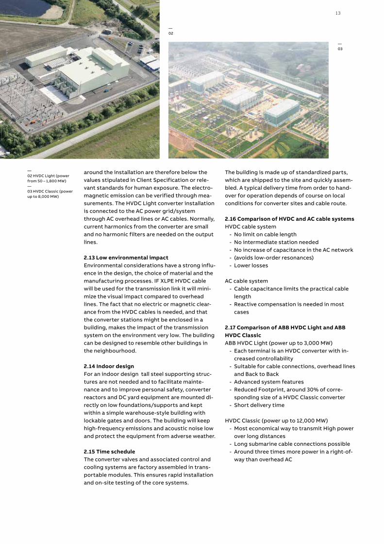
vide remote, off-the-grid locations with reliable, environmentally friendly power supplies. If the re-mote load is located in a tourist or otherwise sen-sitive area, there are reasons other than strict economics to consider a transmission alternative. Fees on pollution and carbon dioxide emissions from diesel generators or gas turbines may also make HVDC transmission solutions more competitive and attractive.
As a bi-product of DC transmission a fibre optic cable could easily be attached to the same infra-structure when laying the cable or installing the transmission line, thus improving the quality of life for the population in the remote location.
A transmission link also makes sense if local re-newable generation such as hydro, solar or wind power exists or is planned, because the surplus energy produced can easily be exported and the back-bone AC network supported as needed.
In the case of sea crossings to islands and penin-sulas, AC cables are only feasible for relatively short distances, in the range of 50-100 km. An HVDC Light® system has no distance limitation.
The HVDC link can be designed for maintenance kept to a minimum and performed during short biannual periods.
Self-commutation, dynamic voltage control, and black-start capability allow compact HVDC Light® transmission to serve isolated loads long-dis-
tance underground or submarine cables. HVDC Light® technology can operate at variable fre-quency to more efficiently drive large compressor or pumping loads using high-voltage motors, making it a viable power alternative for industrial sites.
3.7.1 Reference projectsThe original Gotland sea cable transmission is a 260 MW bipolar HVDC Classic cable transmission from Västervik on mainland Sweden to Ygne on the island of Gotland. It was built in 1954 and ex-panded in 1983 and 1987. The main reason for choosing HVDC transmission was to replace local generation on the island with a more environmen-tally friendly system, and also due to the consid-erable length of the sea crossing from the main-land, 96 km.
In 1999 a 50 MW HVDC Light underground cable transmission was installed from the southern tip of the island in Näs to Bäcks close to the classic HVDC station in Ygne. Wind farms had been in-stalled in the south of the island, and this new re-newable energy generation needed to be evacu-ated. HVDC Light®’s capacity to overcome the power quality problems in wind power plants and the possibility of transmitting the power via un-derground cables also encouraged the local util-ity, GEAB, to install the system. All equipment was mounted in enclosed modules in the factory and were fully factory tested, so that civil works, in-stallation and commissioning was kept to a mini-mum.

30 H V D C LI G HT IT´S T I M E TO CO N N EC T
-DC
+DC
AC
(aux)
4.1 Conceptual designAs for all complex systems, ABB s selected con-ceptual design for HVDC Light is a trade-off be-tween technical performance and cost. Using a solid base of technology modules, developed and refined since the first delivery in 1997, ABB has succeeded in creating a cost efficient converter solution while retaining all of the operational functionalities valued by customers. The design concept is scalable up to the highest transmis-sion voltages, losses are continuously being re-duced and reliability is high.
The development of HVDC Light converter tech-nology has been ongoing. At first it was a straight forward two-level converter switching the full voltage in a PWM pattern. Then came a three-level converter where the losses were reduced, but at a cost of more IGBTs. Further on Light was back to a two-level converter with reduced number of IGBTs, but keeping the losses down by using opti-mized switching pattern and more optimized IGBT design. Next step was the enhanced two-level type, Cascaded two-level Converter which enables the creation of a nearly sinusoidal output voltage from the converter, which in combination with the low switching frequency per cell signifi-cantly reduces station losses.
—01 Simplified circuit diagram of HVDC Light cascaded two-level con-verter. On the positive arm, a single valve cell is pointed out; in the negative arm, an entire valve arm is highlighted.
—HVDC Light technology
Without the extensive experience gained by ABB during step-by-step development and long term operation over several generations of HVDC Light, it would not be possible to offer such a well-proven, reliable and optimized converter sta-tion design down to the smallest building block.
4.1.1 Enhancement of HVDC Light The enhanced version of HVDC Light adopts a multi-level converter structure that will enable output wave from that is nearly identical to a si-nusoidal form. This further eliminates the output performance while reducing switching frequency on semiconductor level. The converter cells are combined in valves in modularized valves that give high availability and optimized maintenance through design for maintenance. The adaption of the BiGT component enables a higher current rat-ing of the valve that result in an increased power rating at a given voltage rating compared to ear-lier versions. Furthermore has great effort been but reducing the physical footprint and optimiz-ing the main circuit equipment in order to benefit from ABBs vast experience of delivering HVDC Light projects.
31
-DC
+DC
AC
(aux)
ULUCUV
I V
L
L
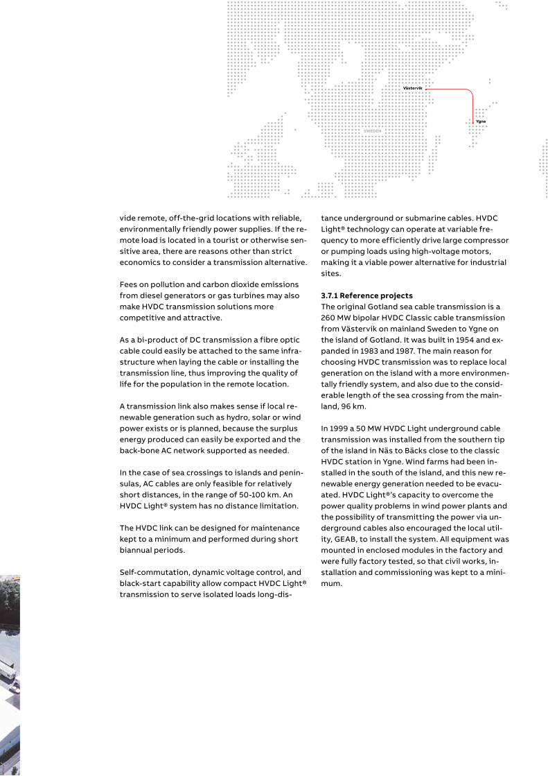
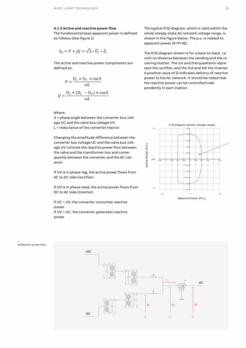
4.1.2 Active and reactive power flowThe fundamental base apparent power is defined as follows (See figure 1)
The active and reactive power components are defined as:
Where: d = phase angle between the converter bus volt-age UC and the valve bus voltage UVL = inductance of the converter reactor
Changing the amplitude difference between the converter bus voltage UC and the valve bus volt-age UV controls the reactive power flow between the valve and the transformer bus and conse-quently between the converter and the AC net-work.
If UV is in phase-lag, the active power flows from AC to DC side (rectifier)
If UV is in phase-lead, the active power flows from DC to AC side (inverter)
If UC > UV, the converter consumes reactive powerIf UV > UC, the converter generates reactive power
—02 Reactive power flow.
The typical P/Q diagram, which is valid within the whole steady-state AC network voltage range, is shown in the figure below. The p.u. is related to apparent power (S=P+iQ).
The P/Q diagram shown is for a back-to-back, i.e. with no distance between the sending and the re-ceiving station. The 1st and 2nd quadrants repre-sent the rectifier, and the 3rd and 4th the inverter. A positive value of Q indicates delivery of reactive power to the AC network. It should be noted that the reactive power can be controlled inde-pendently in each station.
1.25 1 0.75 0.5 0.25 0 0.25 0.5 0.75 1 1.25
1.25
1
0.75
0.5
0.25
0.25
0.5
0.75
1
1.25
P-Q Diagram (whole voltage range)
Reactive Power (P.U.)
Act
ive
Po
wer
(P.
U.)
1.25
1.25−
P φ( )
1.251.25− Q φ( )
H V D C L I G HT TECH N O LO G Y

32 H V D C LI G HT IT´S T I M E TO CO N N EC T
4.2 HVDC Light base modules The different HVDC Light base modules are pre-sented below. The typical power capacity and to-tal losses for different cable lengths are also given for each module. Note that a typical cable size has been chosen for the figures in the tables. The selection of cable size is generally an optimi-
4.2.2 ±150 kV symmetric base modules
4.2.1 ±80 kV symmetric base modules
4.2.3 ±320 kV symmetric base modules
Data for ±80 kV symmetric base modules, typical values
Data for ±150 kV symmetric base modules, typical values
Data for ±320 kV symmetric base modules, typical values
HVDC Light symmetric modules AC Currents
580AAC 1140AAC 1740AAC 2610AAC
DC Voltages
±80 kVDC M1 M2 M3 M3x
±150 kVDC M4 M5 M6 M6x
±320 kVDC M7 M8 M9 M9x
±500 kVDC M10 M11 M12 M12x
±640 kVDC M13 M14 M15 M15x
Symmetric base modules M1 M2 M3 M3x
DC voltage (pole to ground) kVDC 80 80 80 80
Base power MVA 106 209 319 430
AC current AC 580 1,140 1,740 2610
Symmetric base modules M4 M5 M6 M6x
DC voltage (pole to ground) kVDC 150 150 150 150
Base power MVA 200 393 600 766
AC current AC 580 1,140 1,740 2610
Symmetric base modules M7 M8 M9 M9x
DC voltage (pole to ground) kVDC 320 320 320 320
Base power MVA 427 839 1,281 1635
AC current AC 580 1,140 1,740 2610
zation between the production cost of the cable and the economic evaluation of losses. For exam-ple, a larger cross-sectional area results in a more expensive cable, but fewer losses are produced and at a certain cable length, cable life-time and loss evaluation, an optimization point can be found.
—01 Typical layoutHVDC Light 350 MW block—02 Approximate weight: 1,280 tonnes, Example of a 78 MW offshore station.
—01
—02

33
4.2.4 ±500 kV symmetric base modules
4.2.5 ±640 kV symmetric base modules
Data for ±500 kV symmetric base modules, typical values
Data for ±640 kV symmetric base modules, typical values
Symmetric base modules M10 M11 M12 M12x
DC voltage (pole to ground) kVDC 500 500 500 500
Base power MVA 667 1,311 2,001 2554
AC current AC 580 1,140 1,740 2610
Symmetric base modules M13 M14 M15 M15x
DC voltage (pole to ground) kVDC 640 640 640 640
Base power MVA 854 1,678 2,562 3270
AC current AC 580 1,140 1,740 2610
—03 Typical layout HVDC Light 700 MW block.—04 Typical layoutHVDC Light 1,000 MW block
—03
—04
H V D C L I G HT TECH N O LO G Y

34 H V D C LI G HT IT´S T I M E TO CO N N EC T
4.2.6 Asymmetric base modules As previous mentioned also a converter have been introduced to make an asymmetric DC volt-age possible, i.e., voltage from ground to the cho-sen DC voltage level of the pole. Two asymmetric base modules can also be coupled together into a bipolar arrangement, either from the beginning or through expansion at a later stage. (see figure page 29)
The asymmetric base modules are typically bene-
In an asymmetric base module configuration, the ratings and the transfer capability for different cable lengths follow the same principles as for the symmetric configurations described above. The only difference is that only half of the power is available.
4.2.7 Selection of base modules for cable projectsThe optimization of an entire project, including both converters overhead lines and/or cables, must be performed separately for each specific business case, since active/reactive power de-mand, loss evaluation, overhead line length, cable
ficial for transmission systems with:high requirements of reliability and/or availability by using a bipolar arrangement so that only 50 percent of the power is lost following a fault (N-1 criterion)
Need for staged increase of transmitted power Applications with ground or sea electrodes in or-der to save the investment cost of one cable or OH-line section
—01 Bipolar HVDC Light scheme.
HVDC Light asymmetric modules
AC Currents
580AAC 1140AAC 1740AAC 2610AAC
DC Voltages
±80 kVDC M1A M2A M3A M3Ax
±150 kVDC M4A M5A M6A M6Ax
±320 kVDC M7A M8A M9A M9Ax
±500 kVDC M10A M11A M12A M12Ax
±640 kVDC M13A M14A M15A M15Ax
+ DC
neutral
- DC
AC
AC
length, cable cross-sectional area and cable in-stallation must be considered. In general, it is more economical to choose a lower voltage and higher current for short distances.
For longer distances, it is more economical in most cases to choose a higher voltage, even if a higher DC voltage increases the cost of the con-verters. A choice of either a symmetric or asym-metric converter type is typically based on the distance between terminals, reliability require-ments, need for staged increase of power capac-ity and the possibility of using electrodes.

35
4.3 Main circuit & station design
4.3.1 Power transformer The transformer is a single-phase or three-phase AC power transformer with a tap changer, sub-jected to almost no harmonies similar to conven-tional AC transformers. However, for asymmetri-cal configurations, the transformer will be exposed to a DC-offset in the valve side AC volt-ages, which will result in a slightly more compli-cated transformer design. The tap changer is generally located on the valve side for a symmet-rical configuration and on the network side for an asymmetrical configuration, since the tap chang-ers have difficulty in handling the DC-offset.
4.3.2 Converter reactorsThe converter reactor is one of the key compo-nents in the converter station, the main purpose of which is to:
Provide active and reactive power control. The fundamental frequency voltage across the reac-tor defines the power flow (both active and reac-tive) between the AC and DC sides.Limit short-circuit currents through the valves. The converter reactor impedance, in combination with the transformer impedance, defines the short circuit current for the valve diodes.
There are two converter reactors per phase, one for the positive and negative valve arm respec-tively, which each consist of vertical coils, stand-ing on insulators. The CTL converter reactors are no longer stressed by large switching voltages, as was the case in the conventional two-level con-verter topology, but carries both ac and dc cur-rent.
4.3.3 CapacitorsThe main capacitance for the MMC converter to-
—02 Spare power ABB transformer at an HVDC site.
pology is distributed and integrated as a part of each valve cell, instead of being placed at each pole, as in the two-level topology. A pole capaci-tor also exists for the MMC converter, but is con-siderably smaller. The cell capacitor is charged or discharged, depending on the current direction, each time the cell is switched. The cell capacitor is a dry type capacitor.
4.3.4 AC filtersThe output voltage from a MMC converter topol-ogy is already of sinusoidal character with very low harmonic content, but the possible need for AC filters is mainly decided by the requirements put on filter performance, e.g. permissible volt-age distortion, and the harmonic network imped-ances at the point of connection.
4.3.5 DC filtersFor converters directly coupled to a DC cable, no additional DC filters are generally considered nec-essary, since the inherent suppression of any har-monics is sufficient. However, overhead lines di-rectly coupled to the converter station will require a more detailed investigation and the final out-come mainly depends on the project-specific re-quirements put on filter performance.
A typical requirement can be expressed as an equivalent weighted residual current fed into the DC transmission at each station. The current is calculated as where:
- Ieq is the psophometrically weighted, 800 Hz equivalent disturbing current
- Ih is the vector sum of harmonic currents in cable pair conductors and screens at har-monic h
- Phf1 is the psophometric weight at the fre-quency of h times the fundamental frequency
H V D C L I G HT TECH N O LO G Y

36 H V D C LI G HT IT´S T I M E TO CO N N EC T
4.3.6 High-frequency (HF) filtersThe necessarily high dv/dt in the switching of the valves means that HF noise is generated. To pre-vent this HF noise from spreading from the con-verter to the connected power grids, particular attention is given to the design of the valves, to the shielding of the housings and to ensuring proper HF grounding connections.
To further limit HF interference, Radio Interfer-ence (RI) filters may be installed. If power line car-rier (PLC) systems are used nearby in the con-nected power grid, additional PLC filters may be required.
4.3.7 Valves The semiconductor used in HVDC Light is the StakPak™ BiGT (BiModegate bipolar transistor) from ABB Semiconductors. As a conducting de-vice, the bipolar transistor with its low forward voltage drop is used for handling high currents and instead of the regular current-controlled base. The BiGT has a voltage-controlled capaci-tive gate, as in the MOSFET device. A StakPak™ BiGT has two, four or six sub-modules, which de-termine the current rating of the BiGT.
A complete BiGT position consists of a BiGT, a gate unit electronics and a water-cooled heat sink. Each gate unit includes gate-driving circuits, surveillance circuits and optical interface. The gate-driving electronics control the gate voltage and current at turn-on and turn-off, in order to achieve optimal turn-on and turn-off processes of the BiGT. The voltage across the IGBT during switching is measured, and the information is sent to the valve control unit through an optical fiber. The high-voltage electronics connected
across the IGBT provides the gate unit with the current needed to drive the gate and feed the op-tical communication circuits and the control elec-tronics.
The IGBT cellAn HVDC Light valve is built up by cells. A cell con-sists of two switches and one capacitor module One of the switches can, during on state, lead the current through the cell capacitor, whereas the other switch can bypass the capacitor. The flexi-bility of the BiGT as a semiconducting device also makes it possible to block the current immedi-ately if a short circuit is detected.
The valve armIn order for the converter to be able to handle high voltages, several cells are connected in se-ries. A set of series-connected cells from the AC phase to the DC pole is called a valve arm. The main advantage of using this topology is that each switching only corresponds to a small volt-age step, minimizing the harmonics generated by the converter. An HVDC Light converter has six valve arms, two for each phase. The diagram be-low shows the principle schematics of an HVDC Light converter.
Mechanical designThe converter valves are normally mounted in valve halls and built up by a number of series-con-nected, mechanically constructed IGBT cells.
The valve is suspended from the ceiling in the valve hall by polymeric insulators, which makes the valve resistant to earthquakes and other movements. To make a compact design, special corona shields are attached to the valve struc-

37
ture. The BiGTs are water cooled and the water pipes are placed in the bottom of the valve to minimize the risk and consequences of water leakage. All BiGTs and heat sinks in a module are mounted tightly together under very high pres-sure, in order to minimize contact resistance and increase cooling capacity. The assembling method with BiGT cells hanging in the valve hall, together with controlled humidity levels, makes it possible to reduce the distances between high-voltage parts and the surroundings. Most of the HVDC Light converter parts can be pre-as-sembled at the production location to minimize the assembly work on site.
Valve testingThe applicable standard for HVDC Light converter valve testing is IEC 62501. This standard defines how to perform relevant testing for assuring ade-quate electromechanical design, voltage and cur-rent withstand capability, production quality etc. The tests are divided into dielectric, operational and production tests. The dielectric test verifies the electromechanical design with respect to voltage, whereas the operational test verifies the operation of the valve, i.e. current, voltage and temperature stresses. Production tests are per-formed on every BiGT module before delivery, thus ensuring quality and consistency in the pro-duction.
4.3.8 Valve cooling systemAll HVDC Light positions are equipped with wa-ter-cooled heat sinks providing high-efficiency cooling. To be able to use water as cooling liquid in direct contact with high voltage potentials, it is of great importance that the water has very low conductivity. The water is circulating through the heat sink in close contact with each BiGT, which efficiently transports the heat away from the semiconductor. The cooling water circuit is a closed system, and the water is cooled through
Customer
Station
Responsible departmentProject
Prepared
Approved
Title
Document kind Cont. pagePage No
Lang.
Rev. id.Status Doc. Id.
Customer doc. id. Cust. rev. id.
Ref. designation Function Ref. designation Product
We
rese
rve
allr
ight
sin
this
docu
men
tand
inth
ein
form
atio
nco
ntai
ned
here
in.
Rep
rodu
ctio
n,us
eor
disc
losu
reto
third
parti
esw
ithou
texp
ress
auth
ority
isst
rictly
forb
idde
n.©
AB
BA
B(S
E)
DCC
Single Line Diagram Draft -1.-01
A A
B B
C C
D D
E E
F F
G G
H H
J J
K K
L L
M M
1
1
2
2
3
3
4
4
5
5
6
6
7
7
8
8
9
9
10
10
11
11
12
12
13
13
14
14
15
15
16
16
Converter valves
To DC line
Converter reactorsAC area
To AC network
DC area
To DC line
heat exchangers using either air or a secondary water circuit as cooling medium. The water in the valve cooling system passes continuously through a de-ionizing system, to keep the con-ductivity of the water low. The temperature of the water in the valves is controlled by a MACH-based cooling control system, for example regulating the number of fans to be operated in order to achieve the necessary cooling capacity. In addi-tion to temperature measurements, the cooling system is also equipped with sensors for pres-sure, water flow, level and conductivity, and it controls motor-operated valves, pumps and fans. If necessary, electrical heaters or glycol can be added to prevent the water from freezing if the converter station is located in a cold area.
—01 Single-line diagram of a HVDC Light converter

38 H V D C LI G HT IT´S T I M E TO CO N N EC T
All major parts of the valve cooling system are provided with redundant equipment. The control system consists of two separate systems that measure all parameters using different transmit-ters, all in order to minimize the risk of an un-wanted stop. Both systems are able to control the two main pump motors, and the low-voltage switchgear has switchover functions to ensure uninterruptible operation. The software also per-forms weekly changeovers of the pumps in opera-tion, in order to ensure equal wear of the equip-ment. The redundancy of all the equipment also simplifies the maintenance of the valve cooling system. If maintenance is necessary, it is possible to change which pump will run manually directly from the operator computer. Some parts of the cooling system can be closed and disconnected to allow maintenance to be carried out without in-terrupting the power transmission. The valve cooling system used for HVDC Light is based on the valve cooling system used for thyristor valves in conventional HVDC converters since 1980.
4.3.9 Station service powerThe station service power system is vital for reli-able operation. The design of the station service power focuses on:
Redundant power supplies, one from the internal AC bus and one from an external source.
The supply to the internal AC bus can be taken from an additional winding on the converter transformer, if available. In this way, the power supply is guaranteed at all times when the station is in operation. The output voltage is normally around 20 kV, which means that an intermediate transformer is necessary to provide a 400 V sys-tem. The external power supply is generally taken from a local AC system and is used as back-up source.
Valve cooling pumps: the duplicated valve cooling pumps are controlled by frequency converters for maximum flexibility. The frequency converter also makes it possible to use a DC backup source to keep the pump running, if auxiliary power is lost.
Station battery system: the control equipment and other DC loads are supplied from a dupli-cated battery system with a backup time of at least two hours. Critical AC loads within the con-trol equipment, such as servers, computers, LAN switches, etc., are supplied from a DC/AC inverter fed from the station battery and with an auto-matic switchover to the alternative AC supply in the event of inverter failure or overload.

39
4.3.10 Fire protection In general, all areas with sensitive equipment are equipped with air sampling systems. The air sam-pling system can detect smoke at a very early stage, which can prevent unnecessary tripping or shutdown of the station.
If a water pumping system is required, it will con-sist of one electric pump and one standby die-sel-driven pump. A ring main water loop will then be located on the site (underground). It is con-nected to an isolation valve that will bring redun-dancy in the ring main loop for firefighting water. Fire hydrants will be positioned at strategic loca-tions around the site area close to the main loop. Water supply storage will be connected to the firefighting water loop. The signals from the de-tection system and the pumps will be connected to a fire alarm panel in the operator control room.
4.3.11 Civil, installation and commissioningGeneral
- Both the civil engineering works and equip-ment installation are normally contracted to a local contractor, who will perform the works under the supervision of ABB engineers.
On-site inspection and test activities comprise: - Verifications and inspection during civil engi-
neering work - Pre-installation verifications - Verifications during installation - Equipment tests
Testing of subsystems of the HVDC system - Subsystem functional (circuit) tests - Start up of auxiliary systems
System tests of the HVDC system - Terminal test - High-voltage energizing - Terminal operation - Transmission test
In addition to the tests specified above, acceptance tests will be performed according to the contract agreement. During inspections, the environmental impact requirements specified in the various design drawings will also be verified. All tests will be performed or supervised by ABB commissioning engineers and ABB experts. All tests under high-voltage conditions, terminal tests and transmission tests will be directed by ABB’s test manager with the assistance of ABB commissioning engineers, but under full opera-tional responsibility of the customer’s opera-tional organization.
4.3.12 Availability When designing a modern HVDC Light transmis-sion system, one of the main design objectives is to minimize the number of forced outages and to maximize energy availability (EA).
HVDC Light transmission is designed according to the following principles in order to assure high reliability and availability:
- Simple station design - Use of components with proven high reliabil-
ity - Automatic supervision - Use of redundant control systems and equip-
ment - Available spare units - The design must allow maintenance activities
(forced and scheduled) to be performed with minimum curtailment of the system operation
- Scheduled maintenance that requires link shut-down must be minimized
4.3.13 MaintainabilityUnavailability due to scheduled maintenance de-pends both on the design of transmission and on organization of the maintenance work. The mod-ern design of HVDC Light, which incorporates ex-tensive redundancies for essential systems such as cooling systems, duplicated control systems and station service power, allows most mainte-
H V D C L I G HT TECH N O LO G Y

40 H V D C LI G HT IT´S T I M E TO CO N N EC T
nance work to be done with no interruption of op-eration. Scheduled unavailability per year is gen-erally estimated to be below 0.5 percent. The service interval can be designed with a two year interval.
4.3.14 Quality assuranceABB has developed an effective and efficient quality assurance program complying with ISO 9001 (certified by Bureau Veritas) and an environ-ment management system complying with ISO 14000. The know-how acquired by long experi-ence of HVDC projects, solid technical resources and closely developed relations with key sub sup-pliers ensures reliable products in compliance with the specification. All equipment is in line with applicable IEC standards.
The quality assurance program provides tools that ensure the work in different phases is exe-cuted in a predictable manner. Several systems for feedback of experience are used, including follow-up and testing during equipment manu-facturing, installation, commissioning and com-mercial operation.
ABB is working with health, safety and environ-mental issues as highest priority during all phases of project execution. ABB was certified in accordance with ISO 14001 in 1998 and according to OHSAS 18001 in 2009.
4.3.15 Acoustic noiseAcoustic generation of all main equipment can be predicted during the system design preventing and secure that the HVDC Light converter comply to the projects requirements. The sound require-ments usually apply to the areas outside the sta-tion; the space inside the station and the inside of the buildings varies depending on national regu-lations.Common sound requirements for areas outside the station can typically be:
- At the property line ~ 60-65 decibels (dB) - At the nearest residences ~ 40-45 dB
Typical noise sources in the HVDC Light station are: - Power transformers - Converter reactors - Cooling fans for cooling systems - Air-conditioning equipment
+ DC
ACL
IGBT cell
Valve arm
Module
- DC
—01 Bipolar HVDC Light scheme.—02 One IGBT module—03 StakPak™ IGBT with six sub-modules.
—01
—02
—03

41
Prediction modelThe calculation to predict the sound contribution from equipment is usually done in a three-dimen-sional (3-D) model of the plant and its surround-ings. All significant sound sources in the plant are included in the model. The most essential ele-ments of station surroundings which may influ-ence the sound propagation from the station are also included. The 3-D model makes it possible to study different possible layouts and different con-figurations of the equipment for the future sta-tion. The result of the prediction may be shown as a sound contribution map for the area around the station and can also be supplemented with tables containing the exact sound level values for the cho-sen locations of interest.
4.4 System engineering
4.4.1 Feasibility studyDuring the development of a new project, it is com-mon to perform a feasibility study in order to iden-tify any special requirements to be met by the sys-tem design. ABB can supply models of HVDC Light transmissions in PSS®E, DIgSILENT PowerFactory, PSS®NETOMAC as well as PSLF simulation tools.
4.4.2 System design The flow diagram below illustrates the types of engineering required in a delivery project. The main circuit design includes the following de-sign studies:
- Main circuit parameters - Single-line diagram - Insulation coordination - Harmonic performance - Radio interference study - Transient overvoltages - Transient currents - Calculation of losses - Availability calculation - Audible noise study
Control system design specifies the require-ments to be met by the control and protection system, and all the main circuit apparatus. Con-trol system characteristics are optimized during the detailed design phase. The rating includes all relevant continuous and transient stresses. The auxiliary system design includes the design of auxiliary power, valve cooling, the air-condition-ing system and fire protection system. The lay-out of the main circuit equipment is determined by the electro-mechanical design, and the sta-tion design specifies buildings and foundations.
4.4.3 Validation DPSThe performance of the combined AC and DC system is validated in a dynamic performance study (DPS). The setup includes a detailed repre-sentation of the main circuit equipment, and the control model is a copy of the code that will be delivered to site. The AC systems are repre-sented with a detailed representation of the im-mediate vicinity of the AC system. Typical faults and contingencies are simulated to show that the total system responds appropriately.
FSTDuring the factory system test (FST), the control equipment to be delivered is connected to a re-al-time simulator. Tests are performed according to a test sequence list in order to validate that the control and protection system performs as required.
Site testDuring the commissioning of the converter sta-tions, tests are performed according to a test sequence list in order to validate the specified functionality of the system.
H V D C L I G HT TECH N O LO G Y

42 H V D C LI G HT IT´S T I M E TO CO N N EC T
4.5 HVDC Light control and protection system To operate an HVDC Light transmission as effi-ciently as possible, a powerful, flexible and reli-able control and protection system is required. To fulfill current and future requirements, ABB has developed a fully computerized control and pro-tection system using state-of-the-art computers, microcontrollers and digital signal processors connected by high-performance industrial stan-dard buses and fiber optic communication links.
The system is called MACH (Modular Advanced Control for HVDC and SVC), and is designed spe-cifically for converters in power applications. All critical parts of the system are designed with in-herent parallel and serial redundancy and use the same switchover principles as used by ABB for HVDC applications since the early 1980s.
Because of the extensive use of computers and microcontrollers, it has been possible to include very powerful internal supervision, which will eliminate periodic maintenance for the control equipment. As a consequence of placing all func-tions in computers and micro-controllers, soft-ware plays the most important role in system de-sign. By using a fully graphical functional block programming language and a graphic debugging tool running on networked standard computers, it is possible to establish a very efficient develop-ment and test environment to produce high qual-ity programs and documentation.
To achieve high reliability, quality is built into ev-ery detail from the beginning of the engineering design phase. This is assured by careful compo-nent selection, strict design rules and, finally, by the extensive factory system testing of the con-trol system connected to a real-time HVDC simu-lator.
Developments in the field of electronics are ex-tremely rapid at present, and the best way to en-sure that the designs can follow and benefit from this is to build systems based on open interfaces. This is achieved by using international and indus-try standards, as these standards have long life-times and ensure that spare and upgrade parts are readily available.
4.5.1 Control and protection system designThe HVDC Light control and protection system consists of the station control and monitoring servers, operator workstations, control and pro-tection main computers, I/O systems and valve control units typically arranged as shown in the figure below. Thanks to the modularity and high performance of the MACH equipment, the type of hardware and system software used for an ABB HVDC Light control system are the same as in a classic control system. In fact, only the applica-tion software and the valve control differs.
Control system redundancy designThe design criterion for the control system is 100 percent availability for the transmission system, i.e. no single point of failure should interrupt op-eration. Therefore, redundancy is provided for all system parts involved in the power transfer. The redundant control systems are designed as dupli-cated and parallel systems acting as active or hot standby. At any time, only one of the two systems is active, controlling the converter and associated equipment. The other system, the standby sys-tem, is running but the outputs from that system are disabled.
Control system changeoverThe system switchover commands can be initi-ated manually or automatically. If a fault is de-tected in the active system, the standby system automatically takes over control, becoming the

43
active system. The internal supervision giving switchover orders includes hardware supervision, auxiliary power supervision, program execution supervision (stall alarm), memory testing and su-pervision of the communication. The faulty sys-tem (the previously active system) should be checked before being taken back into operation as the standby system. The switchover com-mands are always initiated from the active sys-tem. This switchover philosophy means that a fault or testing activity in the standby system cannot result in an unintentional switchover. Fur-thermore, a manual switchover order to a faulty standby system is not possible.
Protection redundancy designBoth systems have main computer protection, with identical protection functions fed from sep-arate primary sensors. Normally, the protection computers in both systems are active simultane-ously. It is enough that the protections in one computer detect a fault for a protective action to be initiated. In that way, the correct protective ac-tion can be taken even if some measurement is malfunctioning.
To improve the overall reliability of the HVDC Light® transmission, it is important to avoid un-necessary trips caused by control problems. Therefore, some protections initiate a fast changeover of control system before a trip order is given. If the redundant control system is healthy and successfully re-establishes undis-turbed power transfer on the HVDC link, and the power transmission will continue without any protection actions.
Self supervisionInadvertent trips are avoided as each system is provided with extensive self-supervision, which further enhances system reliability. Examples of methods for self-supervision are:Inherent supervision in measuring systemsSupervision of data bus communicationsSupervision of auxiliary power
Any detected failures in the control and protec-tion hardware will result in a request for change-over, which will be executed if a standby system is available and ready to take over. Otherwise, de-pending on the severity of the fault, the system either stays active and only produces an alarm, or orders a trip. As a last resort, there is also hard-wired backup trip logic to handle the loss of both systems.
4.5.2 Main computersTo take full advantage of the rapid electronic de-velopments, the main computers of the MACH system are based on high-performance industrial computer components. This ensures that ABB can take full advantage of the extremely rapid devel-opments in the field of processors and design the control and protection system for the highest possible performance. The main computers are built around COM Express modules with Intel Em-bedded multi core processors, giving the main computers very good performance and, at the same time, very low power consumption. The low power consumption means that the main com-puters can be designed with self-convection cool-ing. Problems with dust and maintenance require-ments connected with forced air-cooling are
GatewayServer
Main Computer System A
SystemServers
OperatorWorkstation
MaintenanceWorkstation
PCPA
Field Bus System A
I/O System 1A
I/O System nA
Valve Control A
Valve Control B
Field Bus System B
I/O System 1B
I/O System nB
Main Computer System B
PCPB
LAN
—01 MACH Control and Protection system structure.
H V D C L I G HT TECH N O LO G Y

44 H V D C LI G HT IT´S T I M E TO CO N N EC T
—01 ABB workers at the Tjele HVDC Light converter station in Denmark
therefore avoided. The main computers are de-signed for mounting on DIN rails in the rear-mounting plane of control and protection cu-bicles.
4.5.3 I/O systemThe interface between the main computers and the rest of the HVDC facility is the I/O system. It is placed in cubicles where electric signals to and from the main circuit equipment is connected to I/O units or distributed out in junction boxes in the switch yard. The I/O units can be of different types such as digital input, digital output, voltage and current measurements and switch control boards. The units are built in a modular design ensures that it is easy to adapt the I/O system to project-specific requirements and also facilitates easy addition of new functions to the control sys-tem. Each redundant system has its own full set of I/O units. The I/O system are connected to the main computer cubicles using optical field bus connections, to avoid electromagnetic interfer-ence.
4.5.4 CommunicationThe communication inside the converter station uses a hierarchy of serial buses. A general rule for the use of serial buses is to use standardized buses and protocols as long as possible. The ob-jective is to ensure a long economic lifetime for the buses and to ensure that the components used to build the bus structures are available from independent sources. The following text gives some examples of used communication protocols:
Local communicationThe local area network used in the control system is based on the ubiquitous IEEE 802.3 standard (Ethernet). Some parts are using layer 2 Ethernet on Gigabit networks to archive short latency, for example between two main computers, and other are based on TCP/IP for communication control
and protection main computers and the various clients on the network such as servers and opera-tor workstations.
Field buses• CAN busISO standard buses, ISO 11898, also known as CAN (Control Area Network), are used for commu-nication with binary type I/O devices (disconnec-tors and breakers etc.), within some parts of the I/O systems. The CAN bus combines a set of properties important for use in an HVDC station, namely:It is a high-speed bus with an efficient short mes-sage structure and very low latencyThere is no master/slave arrangement, which means that the bus is never dependent on the function of any single node to operate correctlyEfficient CRC checks and hardware features to re-move a faulty node from the network.
• eTDM busFiber optic communications on eTDM are used for fast communication between the Digital Signal Processors in the main computers and the I/O system. The eTDM bus in the MACH system is a high-speed, single fiber, optical data bus for digi-tized analog measurements, digital signals, sta-tus information and CAN messages. The eTDM bus is characterized by large data carrying capac-ity, very low latency and “no jitter” operation. This is absolutely essential when used to feed the HVDC controls with high bandwidth measured signals. Each eTDM bus is able to transmit over 1,000,000 samples per second (one sample every µS).
• EtherCATEtherCAT is a high performance standard Ether-net based Field bus, , IEC61158, used for commu-nication between I/O units and the main comput-ers. The bus is used for analog and digital signals using a sampling speed of up to 10kHz.
—01

45
Remote communicationIf station-to-station communication is included, it is handled by communication boards in the main computer of the pole control and protection (PCP) cubicles. This pole-level communication gives a more robust design than a centralized sta-tion-level telecommunication unit. The communi-cation is synchronous and conforms to ISO 3309 (HDLC frames) for high security. If available, a LAN/WAN type of communication is also used. This eliminates the need for special communica-tion boards and provides even higher perfor-mance. ABB has experience with all types of tele-communication, ranging from 50 and 300 bps radio links, via the 1,200, 2,400 or 9,600 bps com-munication links using analogue voice channels, up to high speed links obtained with optical fiber connections.
4.5.5 Control functionsEach HVDC Light converter is able to control ac-tive and reactive power independently by simulta-neously regulating the amplitude and phase angle of the fundamental component of the converter output voltage (refer to section 4.1.3). The gen-eral control scheme of one converter station is shown in the figure below.
DC voltage controlForces the maximum DC system voltage to track the reference setting via feedback control, and produces an active current order. This control function is not accessible to the operator.
Active power controlThe active power control generates a contribu-tion to the DC voltage reference depending on the active power reference. This voltage differ-ence between the stations drives the desired DC current. A feedback control keeps the power at the desired value. When the operator orders a new power setting, the power is ramped to the desired level at a selected ramp speed. It is possi-ble to ramp through zero transmitted power when reversing power direction. Only one station is allowed to be in DC voltage control mode, and this station is controlling the DC voltage. The other station(s) is/are in Active power control mode. If a switch between active power control and DC voltage control is initiated, this is super-vised and coordinated by the control software to make a smooth transition. All other power orders in the system, such as emergency power control actions and frequency control contribution, are also routed via the active power controller. This is to ensure smooth transitions between normal op-eration and automatic system actions.
Reactive power controlThe HVDC Light converter can either generate or consume reactive power, independently in each
station. The reactive power control tracks the ref-erence value and generates a current reference, controlling the reactive power at the network side of the transformer to a level set by the operator. A new operator order is fulfilled by the control sys-tem at a selected ramp speed, giving a smooth change in reactive power. If the AC voltage is out-side the predefined limitations, the converter control will no longer follow the reactive power order; instead it will temporary switch to AC volt-age control in order to keep the AC voltage within limits.
The selection of AC voltage control and reactive power control is exclusive; only one of these con-trol modes is active at a time. The system will up-date the reference value automatically at start-up, shut-down or when changing between the control modes during operation, to have minimal effect on the AC network.
AC voltage controlIf the converter station is set to AC voltage con-trol, the control system tracks the internal AC voltage reference and generates a reference for the current control. AC voltage setting and ramp speed is adjustable by the operator. In AC voltage control, the reactive power can be any value within the PQ capability, as described in 4.1.3. The internal AC voltage reference may differ slightly from the operator setting depending on the droop gain. This means that a higher reactive power load will give a larger difference from the AC voltage order, ensuring stable operation also if the UQ characteristic of the network is flat. This is especially important in strong AC networks.
AC current controlThe AC current control includes two types of reg-ulators; one controlling the active current compo-nent and one controlling the reactive current component. The outputs from the DC voltage control and AC voltage or reactive power control serve as inputs to the AC current control.
The output of the AC Current controller is the con-verter AC voltage reference. This control function is not accessible to the operator.
Converter firing controlConverter Firing Control (CFC) decides how to switch the converter cells in order to achieve the converter AC voltage requested by the AC voltage reference.
Tap changer controlThis device controls the stepping of the trans-former tap changer. The purpose is to keep the converter bus voltage and the relationship be-tween the AC and DC voltage (modulation index) within specified ranges.
H V D C L I G HT TECH N O LO G Y

46 H V D C LI G HT IT´S T I M E TO CO N N EC T
Islanded network controlIf the converter station is connected to an is-landed network, the reactive power and active power is determined by the difference between the total load and total generation within the is-landed network. This means that the converter operates as an infinite source, instead of the nor-mal mode of controlling the active and reactive power to a set point. When a load is connected, there will be an instantaneous change in the transmitted power corresponding to the size of the load.
4.5.6 Additional control functions
Emergency power controlThe fast control of active and reactive power can enhance grid dynamic performance following dis-turbances. For example, if a severe contingency threatens the systems transient stability, fast ac-tive power run-back, run-up or an instant power reversal can be used to maintain synchronized grid operation. Emergency power actions may be initiated by external inputs or signals derived within the control system.
Frequency controlHVDC systems can enhance stability problems by drawing energy from the remote system, and thereby control the local network frequency. Be-cause of its ability to change the operating point instantaneously, HVDC can feed (or reduce) active power into a disturbed system and obtain a much faster frequency control than a generator. Coordi-nation with other control functions, such as emergency power control and islanded network control, is performed automatically in the control system.
Damping controlA converters’ fast control capability can be used to mitigate low-frequency oscillations in the grid by active and/or reactive power modulation. In particular inter-area oscillations, where tradi-tional power system stabilizers are less effective, can generally be handled effectively by means of a well-designed HVDC modulation scheme. The ability to simultaneously modulate active and re-active power also makes the damping effect of HVDC less dependent on its converter location in the AC network.
Overvoltage functionalityThe control system may be configured to react to AC voltage rises above predefined limits. It will then order the converter to consume as much re-active power as possible in order to get the AC voltage back within the normal operating range.
4.5.7 Protections
Protection system philosophyThe purpose of the protection system is to ensure the prompt removal of any element of the electri-cal system in the event of a fault. The protective system is aided in this task by the AC cir-cuit-breakers, which disconnect the AC network from the converters and are capable of de-ener-gizing the converter transformer. Protective actions and effectsWhen a protection operates, the following fault clearing actions are chosen from, depending on the type of fault:
AlarmsAlarms are sometimes generated as a first action to notify the operator that something is wrong, but the system will still continue in operation as before the alarm.
Temporary blockingIf the converter cells suffer from high current or voltage, a temporary turn-off pulse is sent to all IGBT positions. When the current and voltages re-turns to a safe level again, normal operation is re-sumed.
Permanent blockingThe permanent blocking sends a turn-off pulse to all IGBT positions and always precedes the AC cir-cuit-breaker trip.
AC circuit-breaker tripTripping of the AC circuit-breaker disconnects the AC network from the converter equipment. All protective trip orders to the AC circuit-breakers energize both the A and B coils of the breakers through two redundant devices. Two redundant auxiliary power supplies also feed the redundant trip orders.
Set lockout of the AC circuit-breakerIf a trip order has been sent to the AC cir-cuit-breaker, an order to lock out the breaker may also be executed. This is done to prevent the breaker from closing before the operator has in-vestigated the cause of the trip. The operator can manually reset the lockout of the breaker.
Pole isolationThe pole isolation sequence disconnects the DC side (positive and negative poles) from the DC ca-ble. This is done either manually during normal shutdown or automatically by order from protec-tions, for example a cooling water leakage.

47
—01 Control block diagram with simple single-line diagram.
Start breaker failure protectionAt the same time as a trip order is sent to the AC breaker, an order may also be sent to start the breaker failure protection. If the breaker does not open properly within a certain time, the breaker failure protection orders retripping and/or trip-ping of the next breaker.
4.5.8 Human-machine interfaceA well-designed and flexible human-machine in-terface (HMI) is essential, and to avoid human er-rors, all parts of these systems must be easy to use. The HMI must be able to announce alarms and perform operator controls in a safe and reli-able way. For example, several thousands of mea-sured values, indications and alarms of different types need to be handled. All changes in the state of these signals must be recorded and time tagged with high resolution for accurate re-al-time and post-fault analysis.
The integrated HMI used by ABB, the Station Con-trol and Monitoring (SCM) system, employs ad-vanced software concepts with regard to system
openness, flexibility and ergonomic aspects. The SCM system comprises several operator worksta-tions (OWS) and servers.
The SCM system integrates a large number of fea-tures such as:
- Control of the HVDC Light from process im-ages
- Sequential event recorder - Archiving of events - Powerful alarm handling via list windows - Effective user-defined data filtering - Flexible handling of both on-line and historical
trends - On-line help functions and direct access to
plant documentation - Transient fault recording and analysis - Remote control via gateway station communi-
cation interface
Converter FiringControl
Reactive Power Control
AC Voltage Control
Active Power Control
Operator Input
Path of informationAC Voltage Reference
Reactive Power Reference
Active Power Reference
iprim
upcc
fpccuc
iv,pos
iv,neg
TCpos
Measurementupcc
Qmeas (calculated from upcc and ipcc)
udc,pos
udc,neg
Valve Control
Pmeas (calculated from
upcc and ipcc)
Active Power Control Activated? AC Voltage
Control?
Islanded Network Operation?
Tap Changer Control
TCposucupcc
udc,pos
udc,neg
DC Voltage Control
udc,pos udc,neg
AC Current Control
iv,posiv,neg
Islanded Network Control fpcc
upcc
uc
H V D C L I G HT TECH N O LO G Y
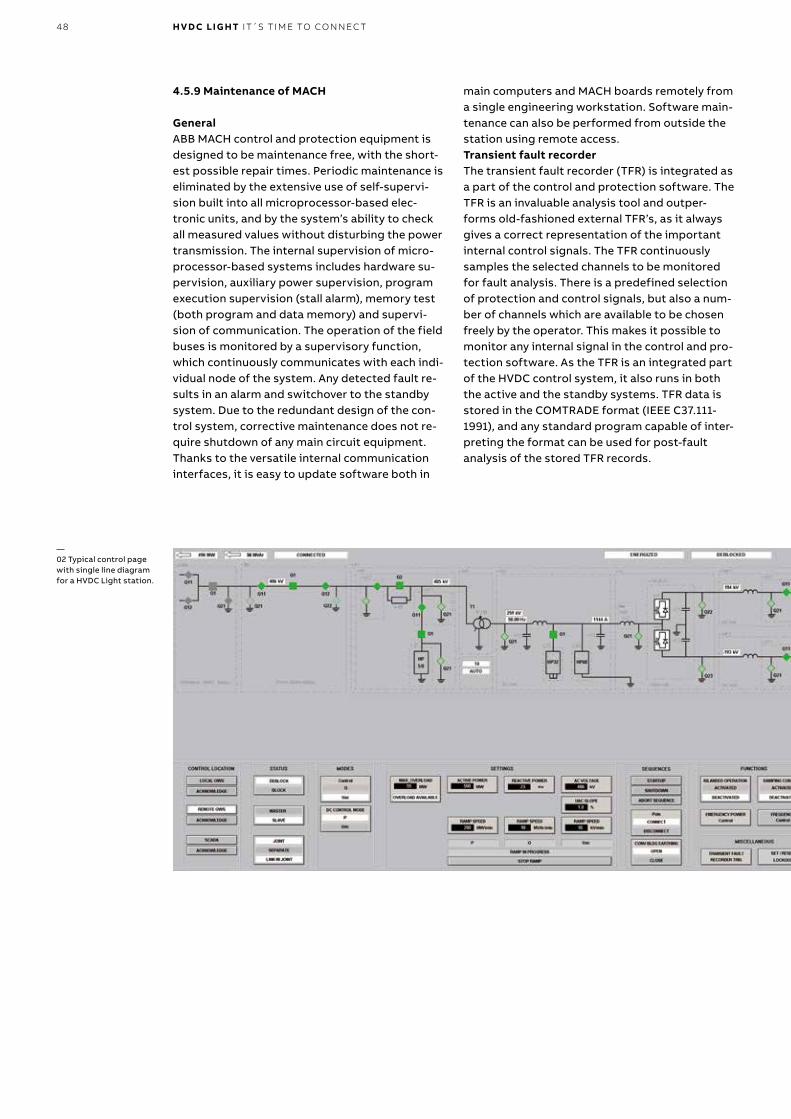
48 H V D C LI G HT IT´S T I M E TO CO N N EC T
4.5.9 Maintenance of MACH
GeneralABB MACH control and protection equipment is designed to be maintenance free, with the short-est possible repair times. Periodic maintenance is eliminated by the extensive use of self-supervi-sion built into all microprocessor-based elec-tronic units, and by the system’s ability to check all measured values without disturbing the power transmission. The internal supervision of micro-processor-based systems includes hardware su-pervision, auxiliary power supervision, program execution supervision (stall alarm), memory test (both program and data memory) and supervi-sion of communication. The operation of the field buses is monitored by a supervisory function, which continuously communicates with each indi-vidual node of the system. Any detected fault re-sults in an alarm and switchover to the standby system. Due to the redundant design of the con-trol system, corrective maintenance does not re-quire shutdown of any main circuit equipment. Thanks to the versatile internal communication interfaces, it is easy to update software both in
main computers and MACH boards remotely from a single engineering workstation. Software main-tenance can also be performed from outside the station using remote access.Transient fault recorderThe transient fault recorder (TFR) is integrated as a part of the control and protection software. The TFR is an invaluable analysis tool and outper-forms old-fashioned external TFR’s, as it always gives a correct representation of the important internal control signals. The TFR continuously samples the selected channels to be monitored for fault analysis. There is a predefined selection of protection and control signals, but also a num-ber of channels which are available to be chosen freely by the operator. This makes it possible to monitor any internal signal in the control and pro-tection software. As the TFR is an integrated part of the HVDC control system, it also runs in both the active and the standby systems. TFR data is stored in the COMTRADE format (IEEE C37.111-1991), and any standard program capable of inter-preting the format can be used for post-fault analysis of the stored TFR records.
—02 Typical control page with single line diagram for a HVDC Light station.

49
Transformer Differential Protection
Transformer and Main AC Bus
Overcurrent Protection
Transformer Protective Relays
Transformer Restricted Earth Fault Protection
Circuit Breaker Failure Protection
Pre - Insertion ResistorProtection
Converter Differential Protection
Converter Bus Abnormal Voltage Protection
Converter Bus Earth Ground Fault Protection
Harmonic OverloadProtection
Converter Overcurrent Protection
IGBT Short CircuitProtection
IGBT Failure Protection
Valve Cooling Protection
Abnormal Cell Voltage Protection
Abnormal Pole Voltage Protection
DC Voltage Unbalance Protection
DC Cable Fault Indication
—01 Simple single-line diagram with examples of protection functions.
H V D C L I G HT TECH N O LO G Y

50 H V D C LI G HT IT´S T I M E TO CO N N EC T
ABB’s goal is to maintain high availability and reli-ability in HVDC systems for our customers around the world, supported by ABB’s global footprint and unmatched capacity to act locally in collaboration with customers and partners. ABB commits to the entire system lifecycle, striving always to earn and maintain customer trust over the long term. Our people have extensive experience with HVDC sys-tems, while our process and service solutions safely optimize the lifecycle of customer systems.
During the warranty period of an HVDC system de-livery contract, we work with customers to mini-mize future outages and unnecessary stoppages. Following a customer takeover, an ABB support team takes responsibility for all issues that may arise during the warranty period. With a post-war-ranty service contract, an ABB HVDC support team proactively schedules preventive support activi-ties and also handles any rapid response issues that may arise.
—HVDC CareLifecycle Services for HVDC
Health and Safety is a top ABB priority, encom-passing all employees, contractors, visitors and the public. ABB staff strive to maintain a safe and healthy working environment at all production sites and facilities by ensuring that adequate steps are taken to prevent accidents and injuries and minimize the hazards inherent in the working environment as far as is reasonably practicable. At the job site Health and Safety is always our first priority, and zero injuries is our expectation and goal.
Lifecycle Services for HVDC consists of service categories divided into service products, each with a specific customer value.
We keep the power flowing, always strive for our customers trust, and never leave our Customer.
—01 Lifecycle Services for HVDC consists of service categories divided into service products, each with a specific customer value.
Lifecyclemanagement
Rapidresponse
Performanceimprovement
Operationalexcellence
24/7phone
Upgrades
Cybersecurity
Conditionassessment
24/7remote
Partialupgrades
MaintenanceSimulationmodels
24/7on-site
Spareparts
SoftwareupdatesTraining
HVDC systemavailability and
reliability
HVDC Care Agreements

51

52 H V D C LI G HT IT´S T I M E TO CO N N EC T
5.1 Upgrades – boosting efficiency and perfor-mance in existing HVDC stationsAfter some years of operation, an assessment of equipment or systems can extend an installa-tion’s lifecycle and reduce downtime. Not only can updated generation hardware and software de-liver new functionalities, but the upgrade can be completed within a relatively short time, and is a proven, efficient way to prolong high perfor-mance. To upgrade older HVDC installations, ABB adapts modern systems and equipment and inte-grates them into existing systems. Proactively upgrading a system before a severe outage occurs can save time and money. The need for an upgrade mainly depends on a system’s age, the condition of the equipment, and the potential scarcity of spare parts.
Modernizing an HVDC installation has been shown to:
- extend system lifetime - improve availability and reliability - increase cost efficiency - improve performance - increase operating efficiency
5.2 Partial Upgrades – a step-by-step approachAn upgrade may consist of a new control system, new functionality and a new generation of hard-ware and software. Partial upgrades may include one or more of the following items:
- MACH control system - Cooling system - Thyristor valve
5.3 ABB HVDC Care – service tailored to your needsABB’s cutting-edge HVDC systems, upgrades and services are supported by HVDC Care Service Products. This extensive service portfolio can be tailored to the needs of individual systems, pro-viding different levels and options of service de-pending on the type of installation and its lifecy-cle status.
Customers need to focus on the core business of providing reliable power throughout the entire life cycle of an HVDC investment. ABB HVDC Ser-vice provides a lifetime of experienced technical support from the company that invented HVDC transmission and built the world’s first commer-cial HVDC power link more than 60 years ago. As well as designing and building HVDC systems, ABB has serviced, upgraded and refurbished HVDC installations around the world, including systems built by other manufacturers. HVDC Care provides a HVDC Care Agreements; 24/7 remote and on-site support; maintenance support; cyber security support; spare parts sup-port; training, and everything else that is needed to service HVDC systems and equipment.
5.4 HVDC Care Agreements – flexible service adapted to your needsA service agreement defines the level of service re-quired, the period of validity, and whether it is a re-current (licensed) support plan or a one-time deliv-ery. HVDC support services are available for all phases of an installation’s life cycle, and in many cases, corrective action is needed only occasion-ally. ABB is committed to the concept of custom-ized support, and provides several service options.
ABB HVDC 24/7 rapid response provides expert support via phone, e-mail, or another agreed means of contact. Quick response from a knowl-edgeable ABB engineer provides customers with immediate access to solutions, saving valuable time. Minor incidents can be quickly resolved, and in the event of a major issue, immediate support is available. Remote service allows ABB to imme-diately start troubleshooting and monitoring a converter station from a secure remote location within the ABB network.
ABB recommends Rapid Response Service (24/7 phone support, corrective maintenance, and other optional HVDC Care Service Products customized to specific needs). HVDC Care is the foundation an ABB HVDC Care Agreements. Upgrade projects are handled as separate agreements.
5.5 ABB Ability™ - HVDC digital solutionsThe ABB Ability portfolio of digital solutions helps HVDC customers take full advantage of digitaliza-tion in their installations, ranging from remote monitoring to systems that maximize availability, reliability and security. Many customers have al-ready deployed these solutions.
ABB Ability brings together all of our digital products and services.ABB digitalization for HVDC is built on ABB’s ex-tensive knowledge of HVDC systems, OT & IT technology, critical infrastructure and digital ex-pertise. These products include:
- Cyber security for HVDC - SW updates and backups for HVDC - Remote assistance for HVDC - MACH control and protection systems for
HVDC - Digital site assessment and maintenance tools
providing customers with system insights and optimized planning.
- Digital models and studies
ABB has used digital solutions for many years to support the reliability and availability of customer installations, and has long been committed to op-timal cyber security standards. ABB experts con-tinuously monitor evolving cyber security stan-dards and adapt ABB systems and processes to meet evolving requirements.

53

54 H V D C LI G HT IT´S T I M E TO CO N N EC T
A common challenge of planning power networks is the difficulty of investigating a full range of op-tions and solutions. To help customers identify best alternatives, ABB has developed a simulation model for complex components that demon-strates whether HVDC technology is the best pos-sible network solution.
The concept involves a common model of HVDC converters in as many simulation tools as possible. Developers use accustomed simulation programs while accessing and integrating simulations of the latest HVDC technology. The common model com-ponent is a set of tool-independent code repre-senting the full control functionality of HVDC Light® to ensure performance is virtually identical between different RMS simulation tools.
The ABB model interacts with different simulation programs and the user’s network to demonstrate the operation and control of HVDC converter mod-els. Load flow and dynamic simulations help plan-ners visualize the impact of an HVDC plant on the power network.
—HVDC digital models
Presently, HVDC Light (based on voltage source converter (VSC) technology) and HVDC Classic (based on line commutated converter (LCC) tech-nology) models are available for simulation tools PSS/E (version 28 - 33) and DIgSILENT PowerFac-tory power system analysis software (version 14 and 15). The HVDC Light model is also available in PSS®NETOMAC. More interfaces are coming, and ABB is committed to maintaining its models to the latest software.
ABB’s HVDC simulation packages come in a self-extracting, executable file that contains com-piled code for the HVDC model, a user’s guide and benchmark examples of a wide variety of cases. Download requires a login, and requests for access are sent via the ABB HVDC web page www.abb.com/hvdc. Under the heading, Our offering, select Service, then System simulation models. Regis-tered users will be informed of new versions and can obtain support and provide feedback about the models via an e-mail address that will be pro-vided when access is granted.

55
All reference is availibe on http://new.abb.com/systems/hvdc Technical papers.
—References

56 H V D C LI G HT IT´S T I M E TO CO N N EC T
—Index
1 Introducing ABB HVDC .......................................................................................................... 4
1.1 This is ABB HVDC .................................................................................................................. 4
1.2 The benefits of ABB HVDC ................................................................................................... 4
1.3 The development of HVDC technology ............................................................................... 4
1.4 The development of HVDC Light technology .................................................................... 6
1.5 Market outlook ...................................................................................................................... 6
1.6 How can HVDC support renewable energy systems? .........................................................7
1.7 What else can HVDC do? .......................................................................................................7
1.8 Lifetime service support for HVDC installations ................................................................7
2 This is HVDC Light ...............................................................................................................10
2.1 Independent power transfer and power quality control .................................................10
2.2 Absolute and predictable power transfer and voltage control ......................................10
2.3 Low power operation ..........................................................................................................10
2.4 Power reversal ......................................................................................................................10
2.5 Reduced power losses in connected AC systems ............................................................10
2.6 Increased transfer capacity in the existing system ........................................................10
2.7 Powerful damping control using P and Q simultaneously .............................................. 11
2.8 Fast restoration after blackouts ........................................................................................ 11
2.9 Islanded operation ..............................................................................................................12
2.10 Flexibility in design .............................................................................................................12

57
2.11 Undergrounding ..................................................................................................................12
2.12 No relevant magnetic fields ...............................................................................................12
2.13 Low environmental impact .................................................................................................13
2.14 Indoor design .......................................................................................................................13
2.15 Time schedule ......................................................................................................................13
2.16 Comparison of HVDC and AC cable systems ....................................................................13
2.17 Comparison of ABB HVDC Light and ABB HVDC Classic .................................................13
2.18 Operating Configurations ..................................................................................................16
2.18.1 Back-to-back ........................................................................................................................ 17
2.18.2 HVDC Grid ............................................................................................................................. 17
2.19 Drivers for choosing HVDC Light ........................................................................................ 17
3 Applications ........................................................................................................................ 20
3.1 Connecting remote generation ......................................................................................... 20
3.1.1 Reference projects ............................................................................................................. 20
3.1.2 Solar ......................................................................................................................................21
3.2 Interconnections ..................................................................................................................21
3.2.1 Reference project ................................................................................................................22
3.3 Connecting remote offshore wind ....................................................................................22
3.3.1 Reference projects ............................................................................................................. 24
3.4 DC links in AC grids ............................................................................................................ 25
3.4.1 Reference projects ............................................................................................................. 26
3.5 Power-from-shore .............................................................................................................. 26
3.5.1 Reference projects ............................................................................................................. 26
3.6 City center infeed ................................................................................................................27
3.6.1 Reference projects ............................................................................................................. 28
IN D E X

58 H V D C LI G HT IT´S T I M E TO CO N N EC T
3.7 Connecting remote loads .................................................................................................. 28
3.7.1 Reference projects ............................................................................................................. 29
4 HVDC Light technology ...................................................................................................... 30
4.1 Conceptual design .............................................................................................................. 30
4.1.1 Enhancement of HVDC Light ............................................................................................. 30
4.1.2 Active and reactive power flow ..........................................................................................31
4.2 HVDC Light base modules ................................................................................................. 32
4.2.1 ±80 kV symmetric base modules ...................................................................................... 32
4.2.2 ±150 kV symmetric base modules .................................................................................... 32
4.2.3 ±320 kV symmetric base modules .................................................................................... 32
4.2.4 ±500 kV symmetric base modules .................................................................................... 33
4.2.5 ±640 kV symmetric base modules .................................................................................... 33
4.2.6 Asymmetric base modules ................................................................................................ 34
4.2.7 Selection of base modules for cable projects ................................................................. 34
4.3 Main circut & station design ............................................................................................. 35
4.3.1 Power transformer ............................................................................................................. 35
4.3.2 Converter reactors ............................................................................................................. 35
4.3.3 Capacitors ........................................................................................................................... 35
4.3.4 AC filters .............................................................................................................................. 35
4.3.5 DC filters .............................................................................................................................. 35
4.3.6 High-frequency (HF) filters ............................................................................................... 36
4.3.7 Valves ................................................................................................................................... 36
4.3.8 Valve cooling system ...........................................................................................................37
4.3.9 Station service power ........................................................................................................ 38
4.3.10 Fire protection .................................................................................................................... 39

59
4.3.11 Civil, installation and commissioning ............................................................................... 39
4.3.12 Availability ........................................................................................................................... 39
4.3.13 Maintainability .................................................................................................................... 39
4.3.14 Quality Assurance ............................................................................................................... 40
4.3.15 Acoustic noise ..................................................................................................................... 40
4.4 System Engineering ............................................................................................................41
4.4.1 Feasibility study ..................................................................................................................41
4.4.2 System design ......................................................................................................................41
4.4.3 Validation ..............................................................................................................................41
4.5 HVDC Light control and protection system .................................................................... 42
4.5.1 Control and protection system design ............................................................................ 42
4.5.2 Main Computers ................................................................................................................. 43
4.5.3 I/O system ........................................................................................................................... 44
4.5.4 Communication .................................................................................................................. 44
4.5.5 Control functions ................................................................................................................ 45
4.5.6 Additional control functions ............................................................................................. 46
4.5.7 Protections .......................................................................................................................... 46
4.5.8 Human machine interface .................................................................................................. 47
4.5.9 Maintenance of MACH ....................................................................................................... 48
5 HVDC Care ............................................................................................................................ 50
5.1 Upgrades – boosting efficiency and performance in existing HVDC stations ............ 52
5.2 Partial Upgrades – a step-by-step approach ................................................................... 52
5.3 ABB HVDC Care – service tailored to your needs ............................................................ 52
5.4 HVDC Care Agreements – flexible service adapted to your needs ............................... 52
5.5 ABB Ability™ - HVDC digital solutions ............................................................................. 55
IN D E X

60 H V D C LI G HT IT´S T I M E TO CO N N EC T
6 HVDC digital models ........................................................................................................... 54
References ......................................................................................................................................... 55
Index ............................................................................................................................................... 56
Notes ............................................................................................................................................... 62

61IN D E X

62 H V D C LI G HT IT´S T I M E TO CO N N EC T
—Notes

63N OTE S

AB
B ID
NO
: PO
W0
038
RE
V. 0
9
© Copyright 2017 ABB. All rights reserved. Specifications subject to change without notice.
—ABB ABUno Lamm HVDC CenterSE-771 80 LudvikaSwedenPhone: +46 21 32 50 00
abb.com/hvdc