Embed Size (px)
Citation preview
1
HVDC Transmission Overview
IEEE PES T&D
Conference & Exposition
April 22, 2008
Michael. P. Bahrman, P.E.
HVD
C T
rans
mis
sion
Ove
rvie
w -
2
TopicsHVDC Transmission CharacteristicsTransmission Distance EffectsCore HVDC Technologies
Conventional HVDCVSC-based HVDC
High Power HVDC TransmissionComparison of HVDC & EHV TransmissionApplicationsHVDC Project ExamplesSummary
2
HVD
C T
rans
mis
sion
Ove
rvie
w -
3
Characteristics of HVDC TransmissionControllable - power injected where neededBypass congested circuits – no inadvertent flowFacilitates integration of remote diverse resourcesHigher power, fewer lines, lower losses, no intermediate S/S neededTwo circuits on less expensive lineNo stability distance limitationReactive power demand limited to terminalsNarrower ROW, no EMF constraintsNo limit to underground cable lengthAsynchronous, ‘firewall’ against cascading outages
HVD
C T
rans
mis
sion
Ove
rvie
w -
4
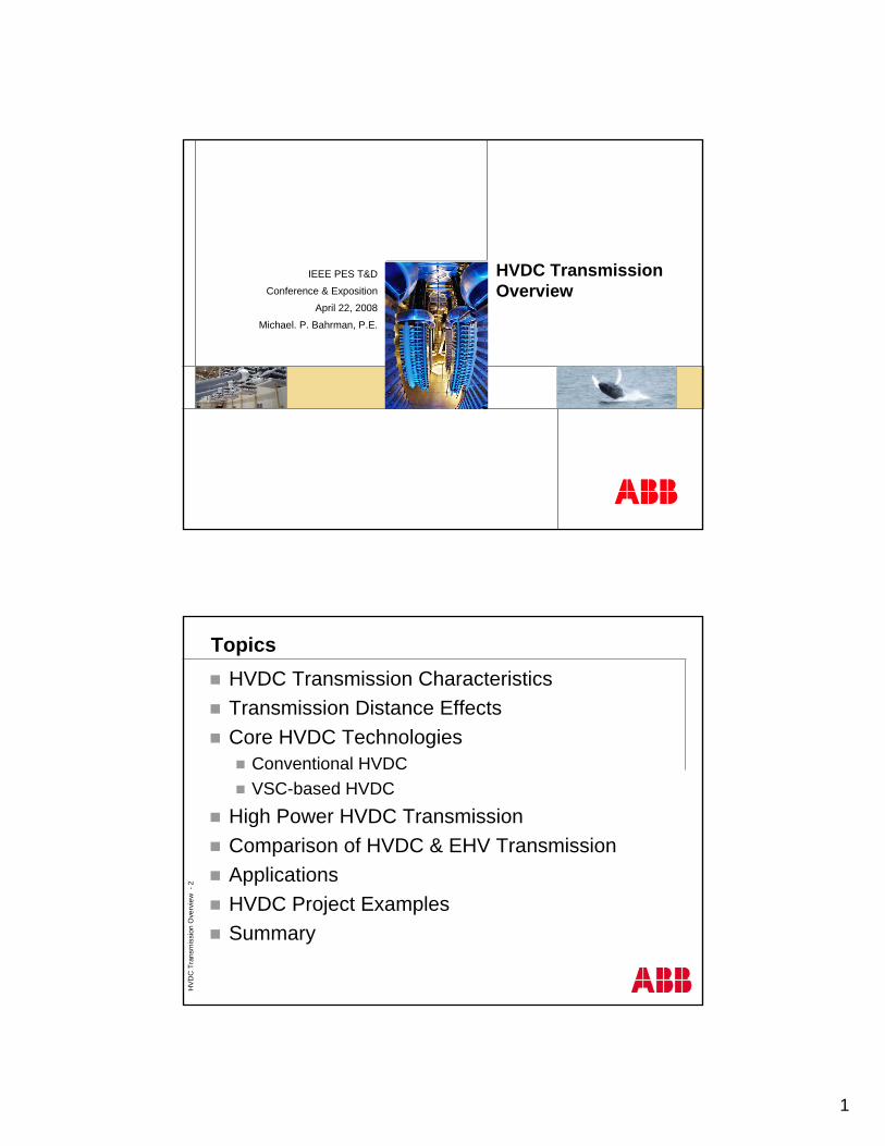
Transmission Line Delivery CapabilityAC line distance effects:
Intermediate switching stations, e.g. every ~250 mi maximumLower stability limits (voltage, angle)Increase stability limits & mitigate parallel flow with FACTS: SVC & SCHigher reactive demand with loadHigher charging at light loadParallel flow issues more prevalentThermal limit remains the same
DC line distance effects:No distance effect on stability (voltage, angle)No need for intermediate stationsNo parallel flow issues due to controlMinor change in short circuit levelsNo increase in reactive power demand
Reactive Power v Power Transfer (200 mi line)
-500
0
500
1000
1500
0 1000 2000 3000 4000 5000
Power Transfer (MW)
Rea
ctiv
e Po
wer
per
Ter
min
al
(MVA
r) 345 kV500 kV765 kV
Max Line Capability v Distance with 3000 A Ratings
0100020003000400050006000
0 100 200 300 400 500 600Transmission Distance (mi)
Max
Lin
e Lo
adin
g (M
W)
345 kV AC
500 kV AC 765 kV AC
± 500 kV DC± 660 kV DC± 800 kV DC
3000 A Limit
3
HVD
C T
rans
mis
sion
Ove
rvie
w -
5
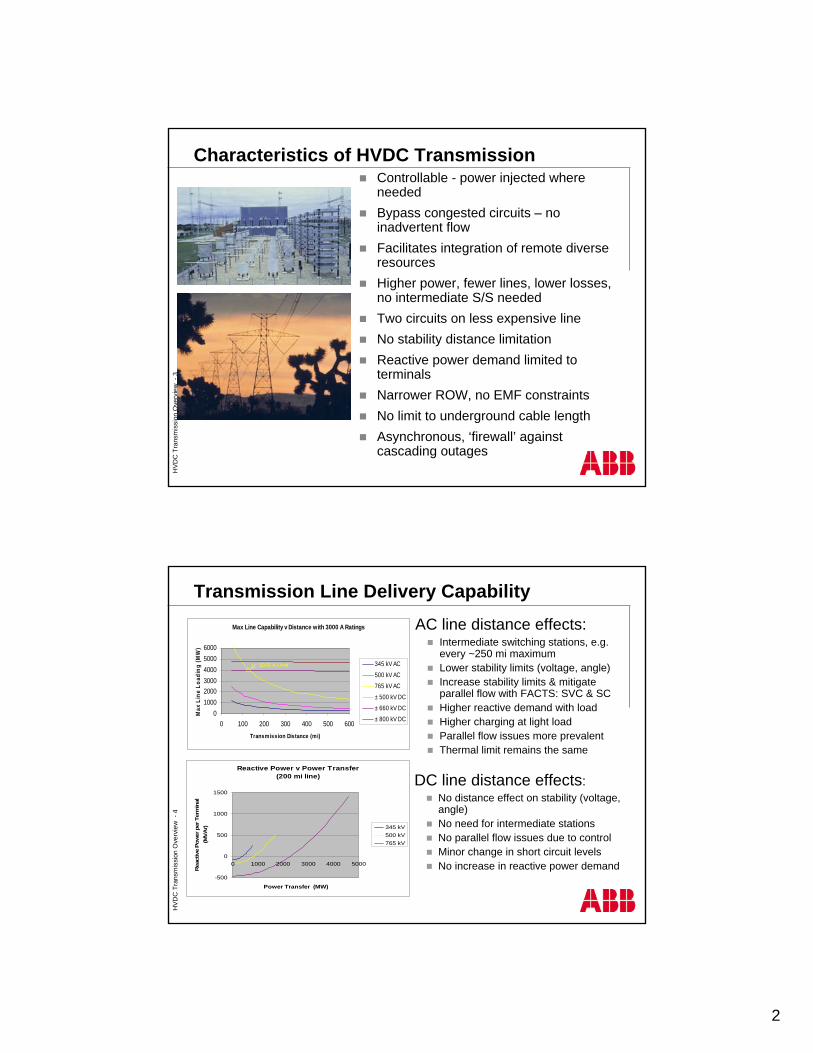
Core HVDC Technologies
AC DC
HVDCHVDC--CSCCSC
Indoor
Outdoor
AC FiltersAC Filters
DC FiltersDC Filters
Thyristor ValvesThyristor Valves
Converter Converter TransformersTransformers
AC DC
HVDCHVDC--CSCCSC
Indoor
Outdoor
AC FiltersAC Filters
DC FiltersDC Filters
Thyristor ValvesThyristor Valves
Converter Converter TransformersTransformers
AC DC
HVDCHVDC--VSCVSC
Indoor
Outdoor
IGBT ValvesIGBT Valves
AC DC
HVDCHVDC--VSCVSC
Indoor
Outdoor
IGBT ValvesIGBT Valves
HVDC ClassicCurrent source convertersLine-commutated thyristor valvesRequires 50% reactive compensation (35% harmonic filter)Converter transformersMinimum short circuit capacity > 2x converter rating, > 1.3x with capacitor commutation
HVDC LightVoltage sourced convertersSelf-commutated IGBT valvesRequires no reactive power compensation (~15% HF)Standard transformersWeak system, black startU/G or OVHDRadial wind outlet regardless of type of wind T-GMore compact
Monopole
HVD
C T
rans
mis
sion
Ove
rvie
w -
6
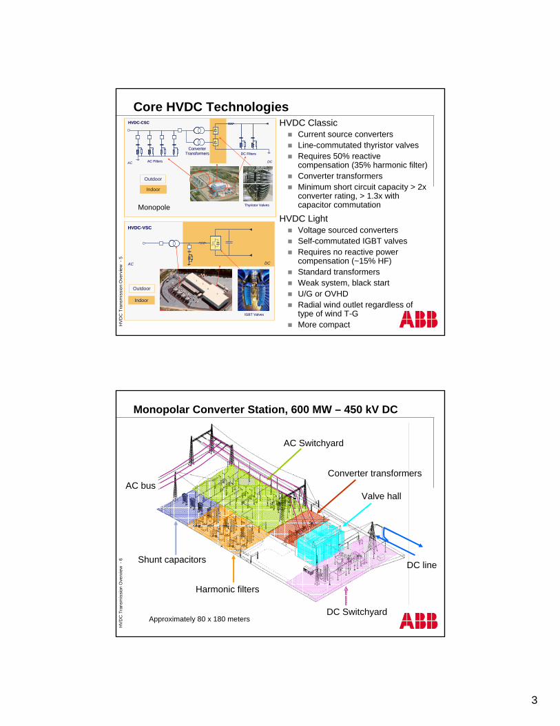
Monopolar Converter Station, 600 MW – 450 kV DC
Shunt capacitors
AC Switchyard
Approximately 80 x 180 meters
AC bus
DC line
Valve hall
Converter transformers
DC Switchyard
Harmonic filters
4
HVD
C T
rans
mis
sion
Ove
rvie
w -
7
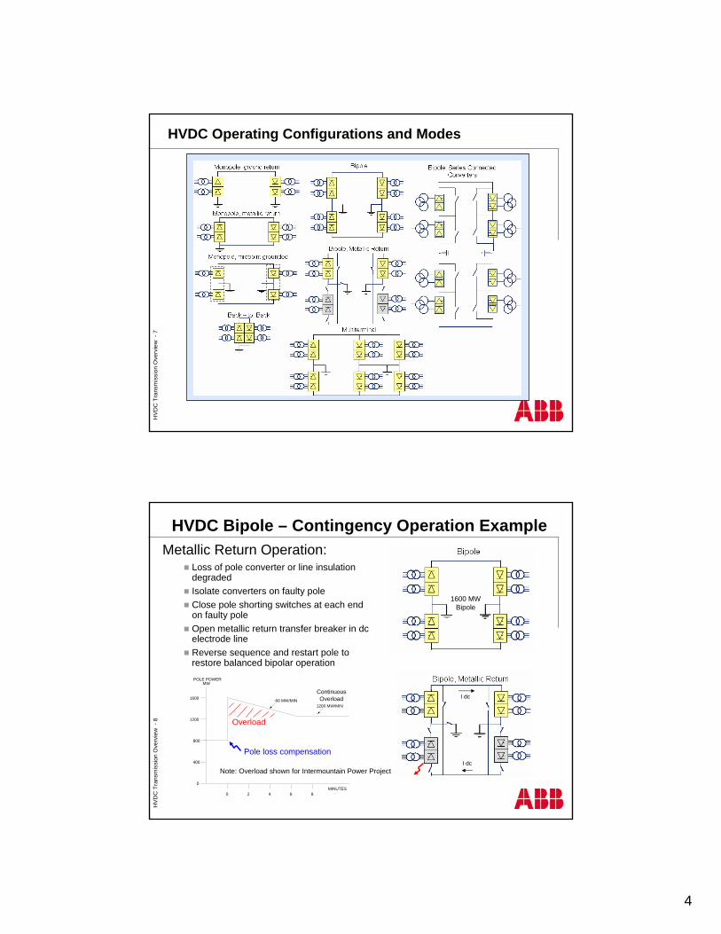
HVDC Operating Configurations and ModesH
VDC
Tra
nsm
issi
on O
verv
iew
-8
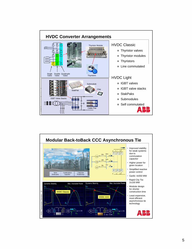
HVDC Bipole – Contingency Operation Example
0
400
800
1200
1600
POLE POWERMW
0 2 64 8MINUTES
-60 MW/MIN1200 MW/MIN
Overload
Pole loss compensation
Metallic Return Operation:Loss of pole converter or line insulation degradedIsolate converters on faulty poleClose pole shorting switches at each end on faulty poleOpen metallic return transfer breaker in dc electrode lineReverse sequence and restart pole to restore balanced bipolar operation
1600 MWBipole
ContinuousOverload I dc
I dcNote: Overload shown for Intermountain Power Project
5
HVD
C T
rans
mis
sion
Ove
rvie
w -
9
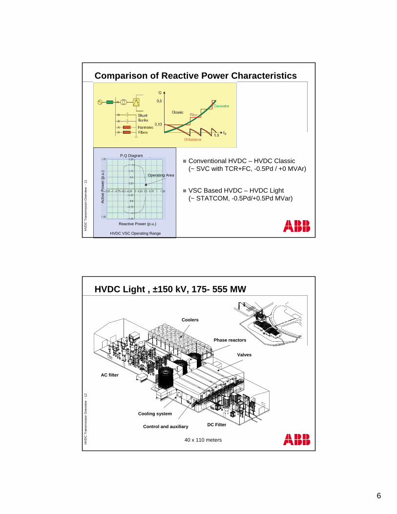
HVDC Converter Arrangements
HVDC ClassicThyristor valves
Thyristor modules
Thyristors
Line commutated
HVDC LightIGBT valves
IGBT valve stacks
StakPaks
Submodules
Self commutated
SingleValve
DoubleValve
QuadrupleValve
Thyristor Module
Thyristors
IGBT Valve Stacks
StakPak
Submodule
Chip
Cable Pair
HVD
C T
rans
mis
sion
Ove
rvie
w -
10
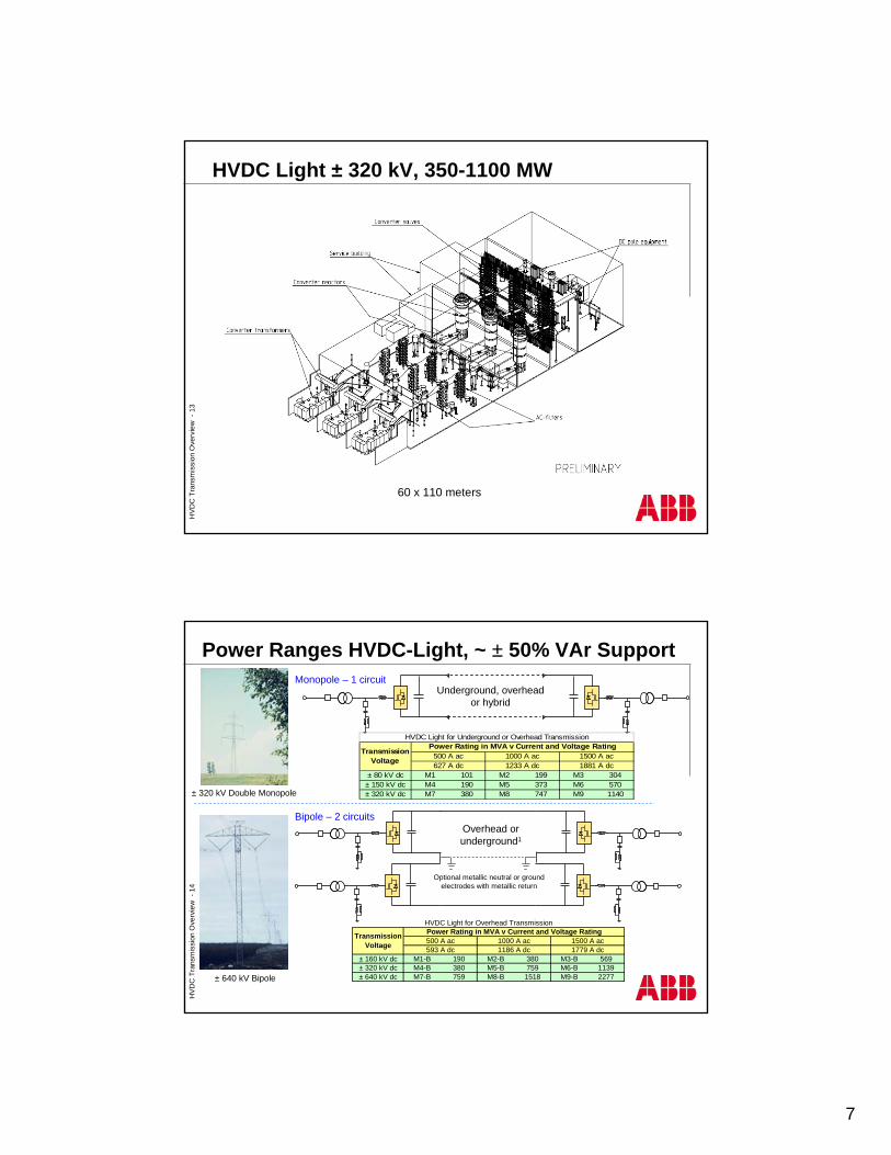
Modular Back-toBack CCC Asynchronous Tie
HVDC Classic
HVDC CCC
Improved stability for weak systems due to commutation capacitor
Higher power for given location
Simplified reactive power control
Garibi: 4x550 MW
Rapid City Tie: 2x100 MW
Modular design for shorter construction time
Least expensive, most efficient asynchronous tie technology
6
HVD
C T
rans
mis
sion
Ove
rvie
w -
11
Comparison of Reactive Power Characteristics
Conventional HVDC – HVDC Classic (~ SVC with TCR+FC, -0.5Pd / +0 MVAr)
VSC Based HVDC – HVDC Light (~ STATCOM, -0.5Pd/+0.5Pd MVar)
Reactive Power (p.u.)
Act
ive
Pow
er (p
.u.)
Operating Area
P-Q Diagram
HVDC VSC Operating Range
HVD
C T
rans
mis
sion
Ove
rvie
w -
12
HVDC Light , ±150 kV, 175- 555 MW
Phase reactors
Coolers
Cooling system
DC Filter
AC filter
Control and auxiliary
Valves
40 x 110 meters
7
HVD
C T
rans
mis
sion
Ove
rvie
w -
13
HVDC Light ± 320 kV, 350-1100 MW
60 x 110 meters
HVD
C T
rans
mis
sion
Ove
rvie
w -
14
± 160 kV dc M1-B 190 M2-B 380 M3-B 569± 320 kV dc M4-B 380 M5-B 759 M6-B 1139± 640 kV dc M7-B 759 M8-B 1518 M9-B 2277
HVDC Light for Overhead Transmission
593 A dc 1186 A dc 1779 A dc
Transmission Voltage
Power Rating in MVA v Current and Voltage Rating500 A ac 1000 A ac 1500 A ac
± 80 kV dc M1 101 M2 199 M3 304± 150 kV dc M4 190 M5 373 M6 570± 320 kV dc M7 380 M8 747 M9 1140
1881 A dc
HVDC Light for Underground or Overhead Transmission
Transmission Voltage
Power Rating in MVA v Current and Voltage Rating500 A ac 1000 A ac 1500 A ac627 A dc 1233 A dc
± 640 kV Bipole
± 320 kV Double Monopole
Underground, overhead or hybrid
Overhead or underground1
Optional metallic neutral or ground electrodes with metallic return
Power Ranges HVDC-Light, ~ ± 50% VAr Support Monopole – 1 circuit
Bipole – 2 circuits
8
HVD
C T
rans
mis
sion
Ove
rvie
w -
15
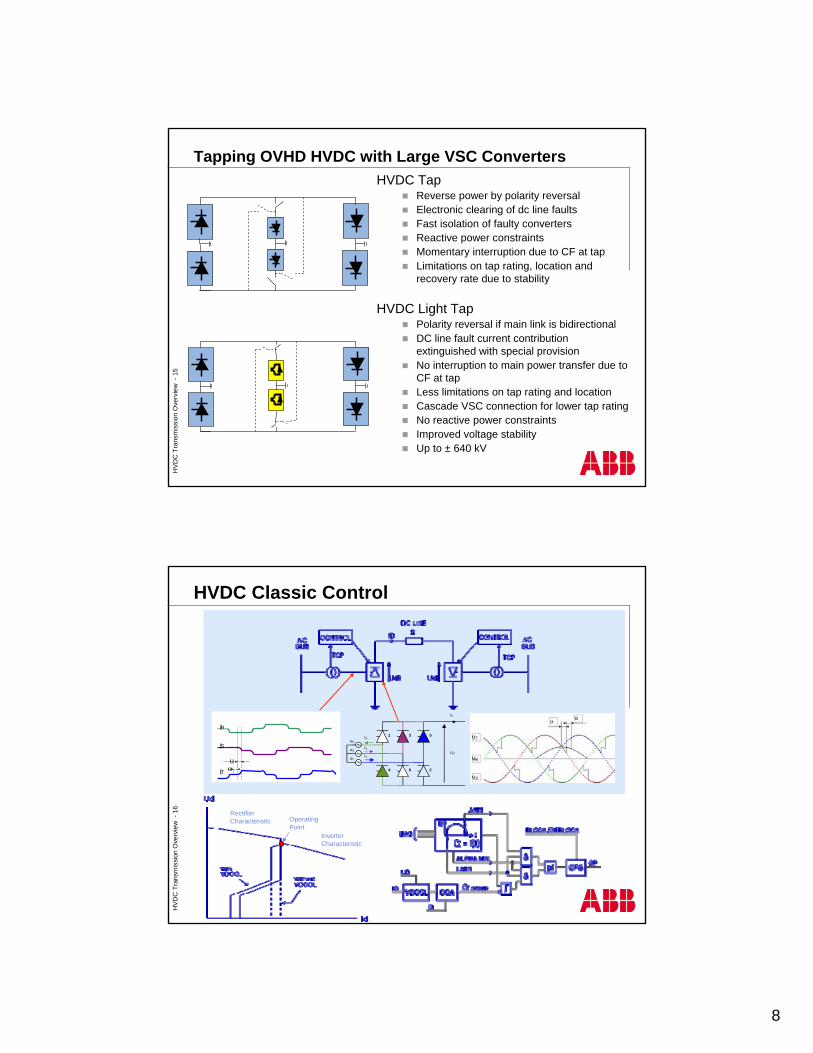
Tapping OVHD HVDC with Large VSC ConvertersHVDC Tap
Reverse power by polarity reversalElectronic clearing of dc line faultsFast isolation of faulty convertersReactive power constraintsMomentary interruption due to CF at tapLimitations on tap rating, location and recovery rate due to stability
HVDC Light TapPolarity reversal if main link is bidirectionalDC line fault current contribution extinguished with special provisionNo interruption to main power transfer due to CF at tapLess limitations on tap rating and locationCascade VSC connection for lower tap ratingNo reactive power constraintsImproved voltage stabilityUp to ± 640 kV
HVD
C T
rans
mis
sion
Ove
rvie
w -
16
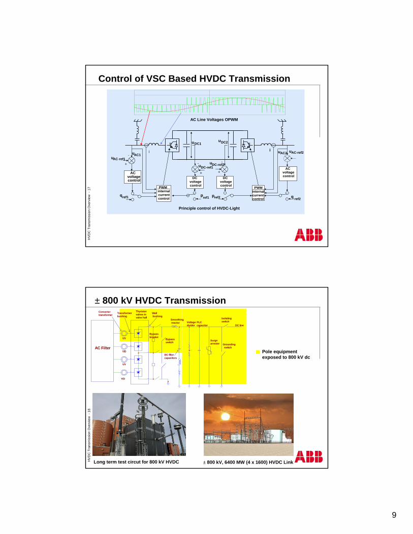
HVDC Classic Control
uR
uS
uT
1 3 5
4 6 2
Id
Ud
IR
IS
IT
IR
IS
αu
IT
Inverter Characteristic
Rectifier Characteristic Operating
Point
9
HVD
C T
rans
mis
sion
Ove
rvie
w -
17
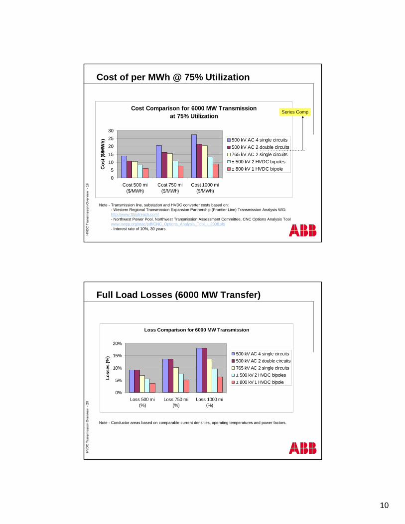
Control of VSC Based HVDC Transmission
Principle control of HVDC-Light
DCvoltagecontrol
uDC-ref1
uDC1
+
-
uAC1uAC-ref1
pref1
DCvoltagecontrol
uDC-ref2
uDC2
+
-
uAC2 uAC-ref2
pref2 q ref2
ACvoltagecontrol
PWMinternalcurrentcontrol
PWMinternalcurrentcontrol
qref1
ACvoltagecontrol
+
-i i
K
K
K
K
AC Line Voltages OPWM
HVD
C T
rans
mis
sion
Ove
rvie
w -
18
Bypassbreaker
Y/D
Y/Y
Convertertransformer
Transformerbushing
Thyristor valves in valve hall
Wall bushing
AC Filter
Y/D
Y/Y
DC line
Grounding switch
Isolating switch
Surgearrester
Smoothing reactor PLC
capacitor
DC filter capacitors
Voltage divider
Bypass switch
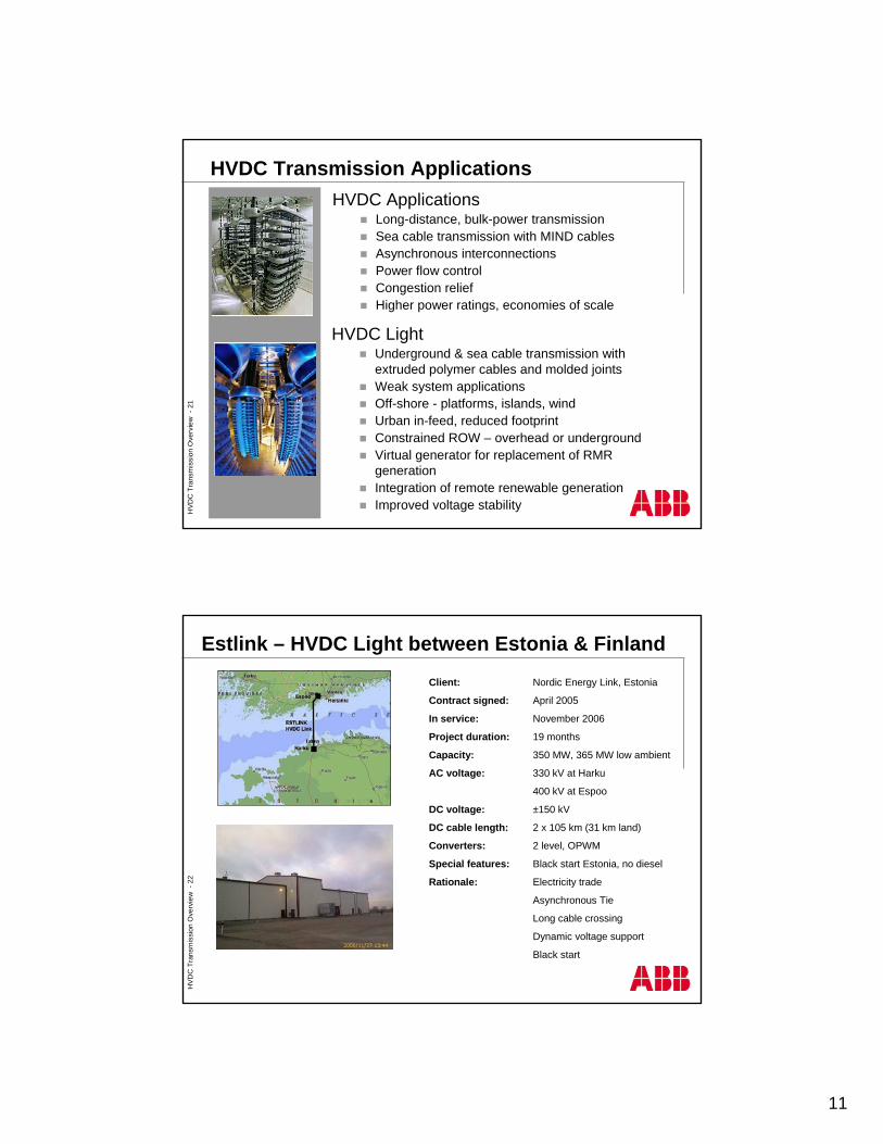
Pole equipment exposed to 800 kV dc
Long term test circut for 800 kV HVDC ± 800 kV, 6400 MW (4 x 1600) HVDC Link
± 800 kV HVDC Transmission
10
HVD
C T
rans
mis
sion
Ove
rvie
w -
19
Cost Comparison for 6000 MW Transmission at 75% Utilization
05
1015
202530
Cost 500 mi($/MWh)
Cost 750 mi($/MWh)
Cost 1000 mi($/MWh)
Cos
t ($/
MW
h) 500 kV AC 4 single circuits500 kV AC 2 double circuits765 kV AC 2 single circuits± 500 kV 2 HVDC bipoles± 800 kV 1 HVDC bipole
Series Comp
Cost of per MWh @ 75% Utilization
Note - Transmission line, substation and HVDC converter costs based on:- Western Regional Transmission Expansion Partnership (Frontier Line) Transmission Analysis WG:http://www.ftloutreach.com/- Northwest Power Pool, Northwest Transmission Assessment Committee, CNC Options Analysis Toolwww.nwpp.org/ntac/pdf/CNC_Options_Analysis_Tool_-_2006.xls- Interest rate of 10%, 30 years
HVD
C T
rans
mis
sion
Ove
rvie
w -
20
Full Load Losses (6000 MW Transfer)
Loss Comparison for 6000 MW Transmission
0%
5%
10%
15%
20%
Loss 500 mi(%)
Loss 750 mi(%)
Loss 1000 mi(%)
Loss
es (%
) 500 kV AC 4 single circuits500 kV AC 2 double circuits765 kV AC 2 single circuits± 500 kV 2 HVDC bipoles± 800 kV 1 HVDC bipole
Note - Conductor areas based on comparable current densities, operating temperatures and power factors.
11
HVD
C T
rans
mis
sion
Ove
rvie
w -
21
HVDC ApplicationsLong-distance, bulk-power transmissionSea cable transmission with MIND cablesAsynchronous interconnectionsPower flow controlCongestion reliefHigher power ratings, economies of scale
HVDC Transmission Applications
HVDC LightUnderground & sea cable transmission with extruded polymer cables and molded jointsWeak system applicationsOff-shore - platforms, islands, windUrban in-feed, reduced footprintConstrained ROW – overhead or undergroundVirtual generator for replacement of RMR generationIntegration of remote renewable generationImproved voltage stability
HVD
C T
rans
mis
sion
Ove
rvie
w -
22
Client: Nordic Energy Link, Estonia
Contract signed: April 2005
In service: November 2006
Project duration: 19 months
Capacity: 350 MW, 365 MW low ambient
AC voltage: 330 kV at Harku
400 kV at Espoo
DC voltage: ±150 kV
DC cable length: 2 x 10⁵ km (31 km land)
Converters: 2 level, OPWM
Special features: Black start Estonia, no diesel
Rationale: Electricity trade
Asynchronous Tie
Long cable crossing
Dynamic voltage support
Black start
Estlink – HVDC Light between Estonia & Finland
12
HVD
C T
rans
mis
sion
Ove
rvie
w -
23
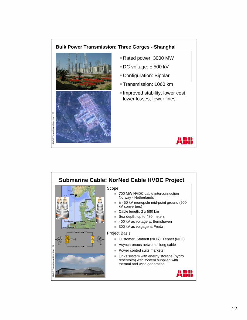
Bulk Power Transmission: Three Gorges - Shanghai
Rated power: 3000 MW
DC voltage: ± 500 kV
Configuration: Bipolar
Transmission: 1060 km
Improved stability, lower cost, lower losses, fewer lines
HVD
C T
rans
mis
sion
Ove
rvie
w -
24
Scope700 MW HVDC cable interconnection Norway - Netherlands± 450 kV monopole mid-point ground (900 kV converters)Cable length: 2 x 580 kmSea depth: up to 480 meters400 kV ac voltage at Eemshaven300 kV ac volgage at Freda
Project BasisCustomer: Statnett (NOR), Tennet (NLD)Asynchronous networks, long cablePower control suits marketsLinks system with energy storage (hydro reservoirs) with system supplied with thermal and wind generation
Submarine Cable: NorNed Cable HVDC Project
13
HVD
C T
rans
mis
sion
Ove
rvie
w -
25
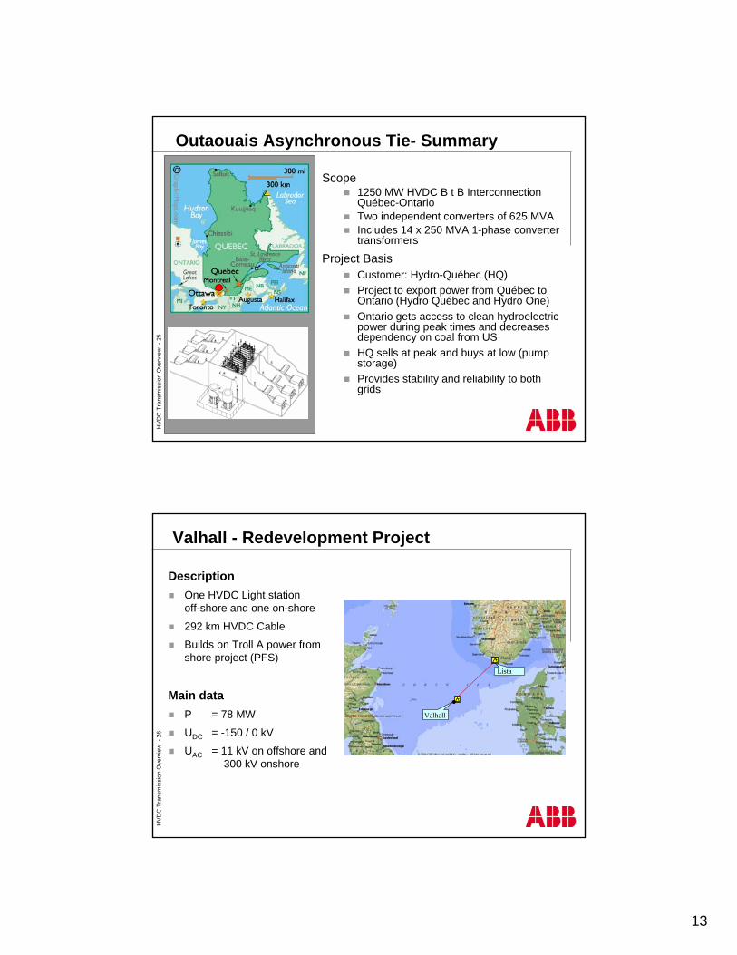
Outaouais Asynchronous Tie- Summary
Scope1250 MW HVDC B t B Interconnection Québec-OntarioTwo independent converters of 625 MVAIncludes 14 x 250 MVA 1-phase converter transformers
Project BasisCustomer: Hydro-Québec (HQ)Project to export power from Québec to Ontario (Hydro Québec and Hydro One)Ontario gets access to clean hydroelectric power during peak times and decreases dependency on coal from USHQ sells at peak and buys at low (pump storage)Provides stability and reliability to both grids
HVD
C T
rans
mis
sion
Ove
rvie
w -
26
DescriptionOne HVDC Light station off-shore and one on-shore
292 km HVDC Cable
Builds on Troll A power from shore project (PFS)
Main dataP = 78 MW
UDC = -150 / 0 kV
UAC = 11 kV on offshore and300 kV onshore
Valhall
Lista
Valhall - Redevelopment Project
14
HVD
C T
rans
mis
sion
Ove
rvie
w -
27
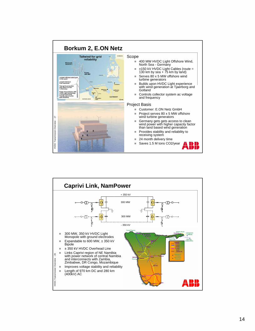
Borkum 2, E.ON NetzScope
400 MW HVDC Light Offshore Wind, North Sea - Germany±150 kV HVDC Light Cables (route = 130 km by sea + 75 km by land)Serves 80 x 5 MW offshore wind turbine generatorsBuilds upon HVDC Light experience with wind generation at Tjaerborg and GotlandControls collector system ac voltage and frequency
Project BasisCustomer: E.ON Netz GmbHProject serves 80 x 5 MW offshore wind turbine generators Germany gets gets access to clean wind power with higher capacity factor than land based wind generationProvides stability and reliability to receiving system24 month delivery timeSaves 1.5 M tons CO2/year
HVD
C T
rans
mis
sion
Ove
rvie
w -
28
Caprivi Link, NamPower+ 350 kV
- 350 kV
300 MW
300 MW
300 MW, 350 kV HVDC Light Monopole with ground electrodesExpandable to 600 MW, ± 350 kV Bipole± 350 kV HVDC Overhead LineLinks Caprivi region of NE Namibia with power network of central Namibia and interconnects with Zambia, Zimbabwe, DR Congo, MozambiqueImproves voltage stability and reliabilityLength of 970 km DC and 280 km (400kV) AC
15
HVD
C T
rans
mis
sion
Ove
rvie
w -
29
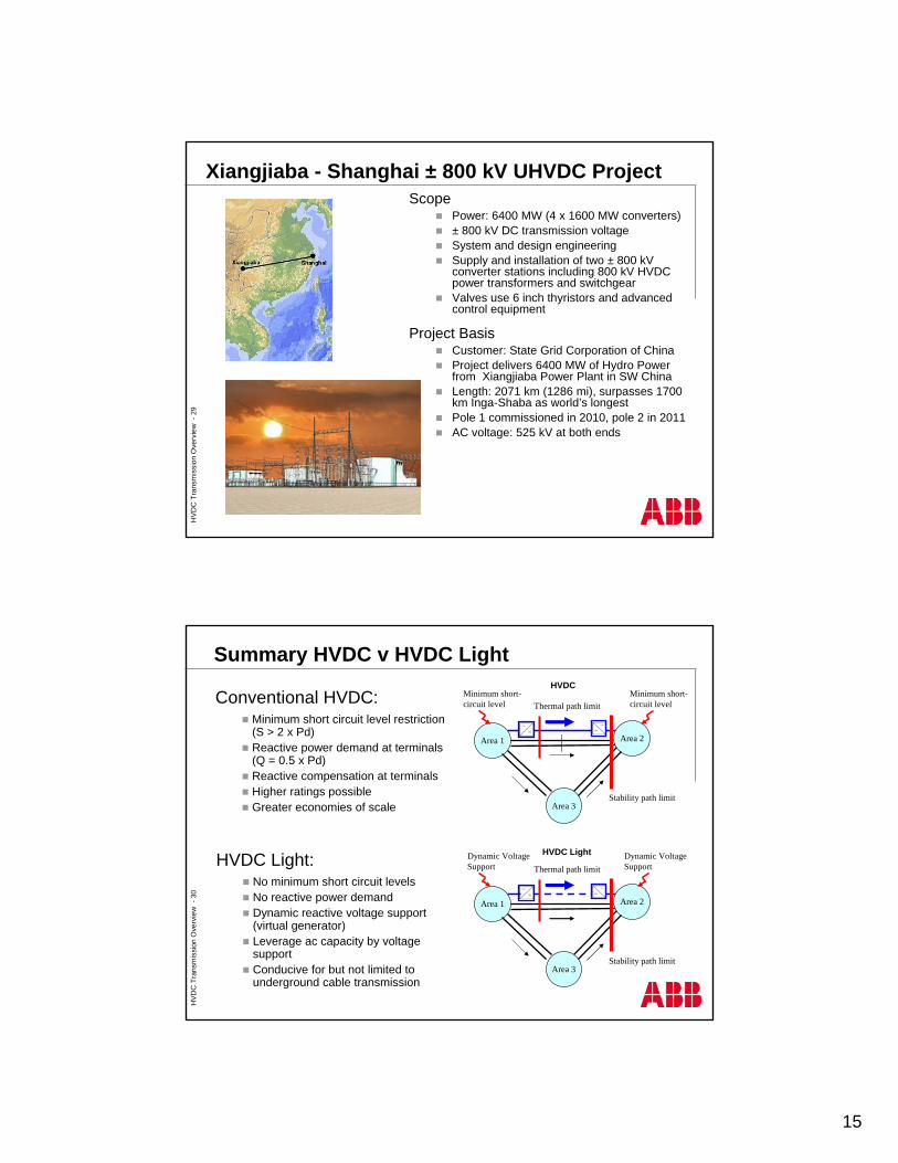
Xiangjiaba - Shanghai ± 800 kV UHVDC ProjectScope
Power: 6400 MW (4 x 1600 MW converters)± 800 kV DC transmission voltageSystem and design engineeringSupply and installation of two ± 800 kV converter stations including 800 kV HVDC power transformers and switchgearValves use 6 inch thyristors and advanced control equipment
Project BasisCustomer: State Grid Corporation of ChinaProject delivers 6400 MW of Hydro Power from Xiangjiaba Power Plant in SW China Length: 2071 km (1286 mi), surpasses 1700 km Inga-Shaba as world’s longest Pole 1 commissioned in 2010, pole 2 in 2011AC voltage: 525 kV at both ends
HVD
C T
rans
mis
sion
Ove
rvie
w -
30
Area 1
Area 3
Area 2
Thermal path limit
Area 1
Area 3
Area 2
Thermal path limit
Stability path limit
Stability path limit
Minimum short-circuit level
Minimum short-circuit level
Dynamic Voltage Support
Dynamic Voltage Support
HVDC
HVDC Light
Conventional HVDC:Minimum short circuit level restriction (S > 2 x Pd)Reactive power demand at terminals (Q = 0.5 x Pd)Reactive compensation at terminalsHigher ratings possibleGreater economies of scale
HVDC Light:No minimum short circuit levelsNo reactive power demandDynamic reactive voltage support (virtual generator)Leverage ac capacity by voltage supportConducive for but not limited to underground cable transmission
Summary HVDC v HVDC Light