Embed Size (px)
Citation preview
HVAC TECHNOLOGY
Lecture_MT_362
Instructor: Mr. Adnan Qamar
1
2
The specific objectives of this chapter are to:
1. Important requirements of an air conditioning duct
2. General rules for duct design
3. Classification of duct systems
4. Commonly used duct design methods
5. Principle of velocity method
6. Principle of equal friction method
7. Principle of static regain method
8. Performance of duct systems
9. System balancing and optimization
10. Introduction to fans and fan laws
11. Interaction between fan and duct system
DESIGN OF AIR CONDITIONING DUCTS
3
At the end of the chapter, the student should be able to:
1. State the important requirements of an air conditioning duct and the general rules to
be followed in the design of ducts
2. Classify air conditioning ducts based on air velocity and static pressure
3. Design air conditioning ducts using velocity method, equal friction method or static
regain method
4. Explain typical performance characteristics of a duct system
5. Explain the importance of system balancing and optimization
6. State and explain the importance of fan laws, and use the performance of fans under
off-design conditions
7. Describe interaction between fan and duct and the concept of balance point
DESIGN OF AIR CONDITIONING DUCTS

INTRODUCTION:
The chief requirements of an air conditioning duct system are:
1. It should convey specified rates of air flow to prescribed locations
2. It should be economical in combined initial cost, fan operating cost and cost of building space
3. It should not transmit or generate objectionable noise
Generally at the time of designing an air conditioning duct system, the required airflow
rates are known from load calculations. The location of fans and air outlets are fixed
initially. The duct layout is then made taking into account the space available and ease of
construction. In principle, required amount of air can be conveyed through the air
conditioning ducts by a number of combinations. However, for a given system, only one set
results in the optimum design. Hence, it is essential to identify the relevant design
parameters and then optimize the design.
4
DESIGN OF AIR CONDITIONING DUCTS
5
DESIGN OF AIR CONDITIONING DUCTS
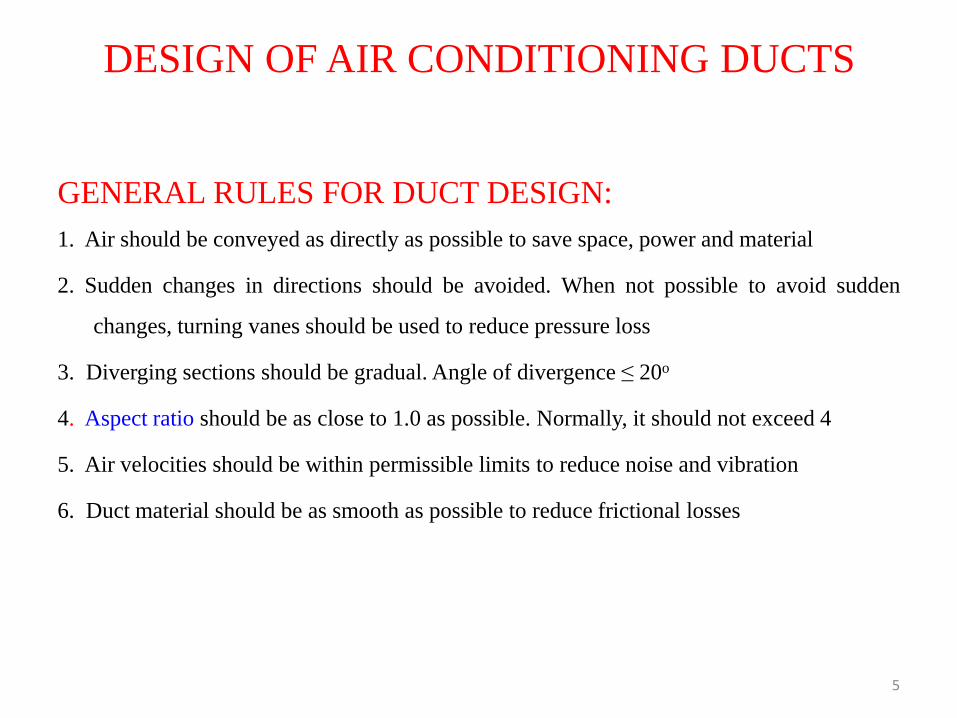
GENERAL RULES FOR DUCT DESIGN:
1. Air should be conveyed as directly as possible to save space, power and material
2. Sudden changes in directions should be avoided. When not possible to avoid sudden
changes, turning vanes should be used to reduce pressure loss
3. Diverging sections should be gradual. Angle of divergence ≤ 20o
4. Aspect ratio should be as close to 1.0 as possible. Normally, it should not exceed 4
5. Air velocities should be within permissible limits to reduce noise and vibration
6. Duct material should be as smooth as possible to reduce frictional losses
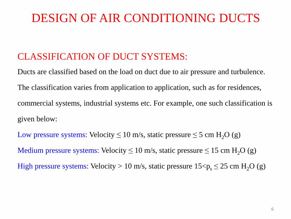
CLASSIFICATION OF DUCT SYSTEMS:
Ducts are classified based on the load on duct due to air pressure and turbulence.
The classification varies from application to application, such as for residences,
commercial systems, industrial systems etc. For example, one such classification is
given below:
Low pressure systems: Velocity ≤ 10 m/s, static pressure ≤ 5 cm H2O (g)
Medium pressure systems: Velocity ≤ 10 m/s, static pressure ≤ 15 cm H2O (g)
High pressure systems: Velocity > 10 m/s, static pressure 15<ps ≤ 25 cm H2O (g)
6
DESIGN OF AIR CONDITIONING DUCTS
7
DESIGN OF AIR CONDITIONING DUCTS
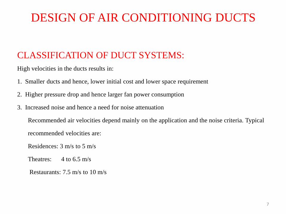
CLASSIFICATION OF DUCT SYSTEMS:
High velocities in the ducts results in:
1. Smaller ducts and hence, lower initial cost and lower space requirement
2. Higher pressure drop and hence larger fan power consumption
3. Increased noise and hence a need for noise attenuation
Recommended air velocities depend mainly on the application and the noise criteria. Typical
recommended velocities are:
Residences: 3 m/s to 5 m/s
Theatres: 4 to 6.5 m/s
Restaurants: 7.5 m/s to 10 m/s
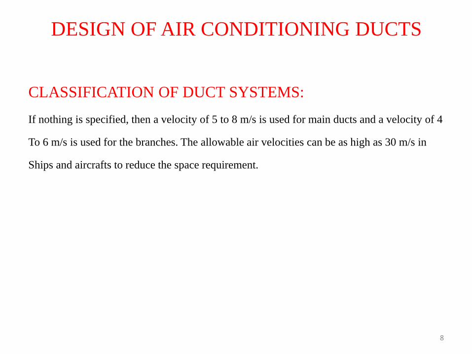
CLASSIFICATION OF DUCT SYSTEMS:
If nothing is specified, then a velocity of 5 to 8 m/s is used for main ducts and a velocity of 4
To 6 m/s is used for the branches. The allowable air velocities can be as high as 30 m/s in
Ships and aircrafts to reduce the space requirement.
8
DESIGN OF AIR CONDITIONING DUCTS
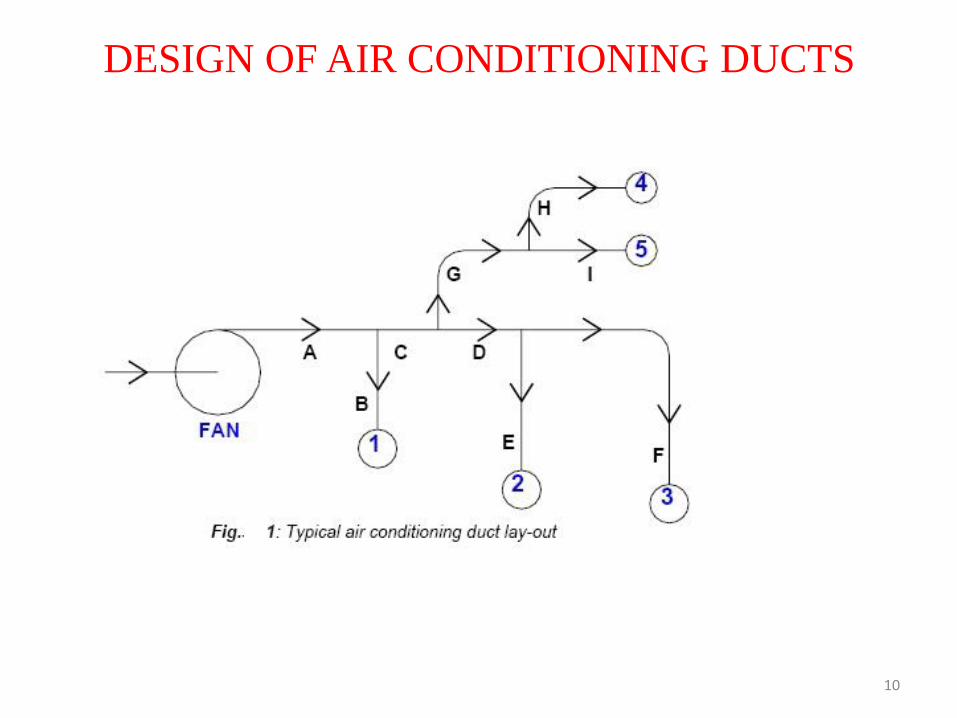
COMMONLY USED DUCT DESIGN METHODS:
Figure.1 shows the schematic of a typical supply air duct layout. As shown in the
figure, supply air from the fan is distributed to five outlets (1 to 5), which are located
in five different conditioned zones. The letters A to I denote the portions of the duct
to different outlets. Thus A-B is the duct running from the supply air fan to zone 1,
A-B-C is the duct running from supply fan to conditioned zone and so on. These are
known as duct runs. The run with the highest pressure drop is called as the index
run. From load and psychometric calculations the required supply airflow rates to
each conditioned space are known. From the building layout and the location of the
supply fan, the length of each duct run is known.
9
DESIGN OF AIR CONDITIONING DUCTS
10
DESIGN OF AIR CONDITIONING DUCTS
COMMONLY USED DUCT DESIGN METHODS:
The purpose of the duct design is to select suitable dimensions of duct for each run and then
to select a fan, which can provide the required supply airflow rate to each conditioned zone.
Due to the several issues involved, the design of an air conditioning duct system in large
buildings could be a sophisticated operation requiring the use of Computer Aided Design
(CAD) software. However, the following methods are most commonly used for simpler lay-
outs such as the one shown in Fig.1.
1. Velocity method
2. Equal Friction Method
3. Static Regain method
11
DESIGN OF AIR CONDITIONING DUCTS
VELOCITY METHOD:
The various steps involved in this method are:
1. Select suitable velocities in the main and branch ducts
2. Find the diameters of main and branch ducts from airflow rates and velocities
for circular ducts. For rectangular ducts, find the cross-sectional area from flow
rate and velocity, and then by fixing the aspect ratio, find the two sides of the
rectangular duct
3. From the velocities and duct dimensions obtained in the previous step, find the
frictional pressure drop for main and branch ducts using friction chart or
equation.
12
DESIGN OF AIR CONDITIONING DUCTS
VELOCITY METHOD:
4. From the duct layout, dimensions and airflow rates, find the dynamic pressure losses for
all the bends and fittings.
5. Select a fan that can provide sufficient FTP for the index run
6. Balancing dampers have to be installed in each run. The damper in the index run is left
completely open, while the other dampers are throttled to reduce the flow rate to the
required design values.
13
DESIGN OF AIR CONDITIONING DUCTS
VELOCITY METHOD:
The velocity method is one of the simplest ways of designing the duct system
for both supply and return air. However, the application of this method requires
selection of suitable velocities in different duct runs, which requires experience.
Wrong selection of velocities can lead to very large ducts, which, occupy large
building space and increases the cost, or very small ducts which lead to large
pressure drop and hence necessitates the selection of a large fan leading to
higher fan cost and running cost. In addition, the method is not very efficient as
it requires partial closing of all the dampers except the one in the index run, so
that the total pressure drop in each run will be same.
14
DESIGN OF AIR CONDITIONING DUCTS

VELOCITY METHOD:
For example, let the duct run A-C-G-H be the index run and the total pressure drop in the
index run is 100 Pa. If the pressure drop in the shortest duct run (say A-B) is 10 Pa, then the
damper in this run has to be closed to provide an additional pressure drop of 90 Pa, so that the
required airflow rate to the conditioned zone 1 can be maintained. Similarly the dampers in
the other duct runs also have to be closed partially, so that the total pressure drop with damper
partially closed in each run will be equal to the pressure drop in the index run with its damper
left open fully.
15
DESIGN OF AIR CONDITIONING DUCTS
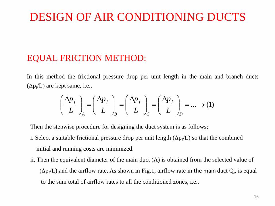
EQUAL FRICTION METHOD:
In this method the frictional pressure drop per unit length in the main and branch ducts
(Δpf/L) are kept same, i.e.,
16
DESIGN OF AIR CONDITIONING DUCTS
Then the stepwise procedure for designing the duct system is as follows:
i. Select a suitable frictional pressure drop per unit length (Δpf/L) so that the combined
initial and running costs are minimized.
ii. Then the equivalent diameter of the main duct (A) is obtained from the selected value of
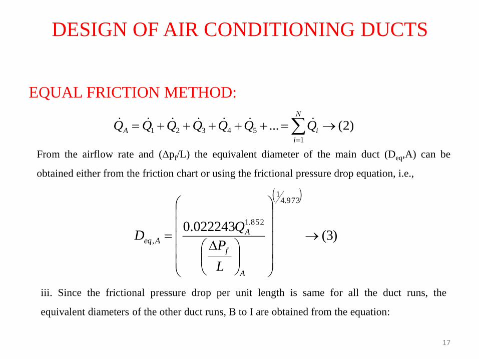
(Δpf/L) and the airflow rate. As shown in Fig.1, airflow rate in the main duct QA is equal
to the sum total of airflow rates to all the conditioned zones, i.e.,
)1(...
D
f
C
f
B
f
A
f
L
p
L
p
L
p
L
p
EQUAL FRICTION METHOD:
17
DESIGN OF AIR CONDITIONING DUCTS
From the airflow rate and (Δpf/L) the equivalent diameter of the main duct (Deq,A) can be
obtained either from the friction chart or using the frictional pressure drop equation, i.e.,
iii. Since the frictional pressure drop per unit length is same for all the duct runs, the
equivalent diameters of the other duct runs, B to I are obtained from the equation:
)2(...1
54321
N
i
iA QQQQQQQ
)3(022243.0
973.41
852.1
,
A
f
AAeq
L
P
QD
18
DESIGN OF AIR CONDITIONING DUCTS
EQUAL FRICTION METHOD:
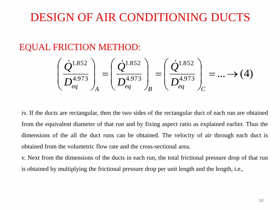
iv. If the ducts are rectangular, then the two sides of the rectangular duct of each run are obtained
from the equivalent diameter of that run and by fixing aspect ratio as explained earlier. Thus the
dimensions of the all the duct runs can be obtained. The velocity of air through each duct is
obtained from the volumetric flow rate and the cross-sectional area.
v. Next from the dimensions of the ducts in each run, the total frictional pressure drop of that run
is obtained by multiplying the frictional pressure drop per unit length and the length, i.e.,
)4(...973.4
852.1
973.4
852.1
973.4
852.1
CeqBeqAeq D
Q
D
Q
D
Q
19
DESIGN OF AIR CONDITIONING DUCTS
EQUAL FRICTION METHOD:
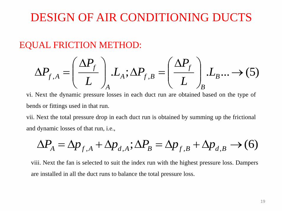
vi. Next the dynamic pressure losses in each duct run are obtained based on the type of
bends or fittings used in that run.
vii. Next the total pressure drop in each duct run is obtained by summing up the frictional
and dynamic losses of that run, i.e.,
viii. Next the fan is selected to suit the index run with the highest pressure loss. Dampers
are installed in all the duct runs to balance the total pressure loss.
)5(....;. ,,
B
B
f
BfA
A
f
Af LL
PPL
L
PP
)6(; ,,,, BdBfBAdAfA ppPppP
20
DESIGN OF AIR CONDITIONING DUCTS
Equal friction method is simple and is most widely used conventional method. This method
usually yields a better design than the velocity method as most of the available pressure drop is
dissipated as friction in the duct runs, rather than in the balancing dampers. This method is
generally suitable when the ducts are not too long, and it can be used for both supply and return
ducts. However, similar to velocity method, the equal friction method also requires partial
closure of dampers in all but the index run, which may generate noise. If the ducts are too long
then the total pressure drop will be high and due to dampering, ducts near the fan get over-
pressurized.
EQUAL FRICTION METHOD:
21
DESIGN OF AIR CONDITIONING DUCTS
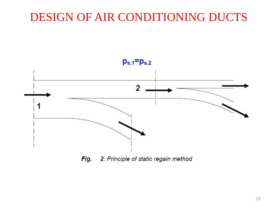
STATIC REGAIN METHOD:
This method is commonly used for high velocity systems with long duct runs,
especially in large systems. In this method the static pressure is maintained same
before each terminal or branch. The procedure followed is as given below:
i. Velocity in the main duct leaving the fan is selected first.
ii. Velocities in each successive runs are reduced such that the gain in static
pressure due to reduction in velocity pressure equals the frictional pressure drop in
the next duct section. Thus the static pressure before each terminal or branch is
maintained constant. For example, Fig.2 shows a part of the duct run with two
sections 1 and 2 before two branch take-offs.
22
DESIGN OF AIR CONDITIONING DUCTS
23
DESIGN OF AIR CONDITIONING DUCTS
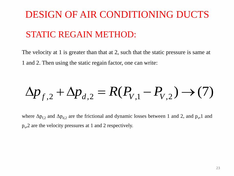
The velocity at 1 is greater than that at 2, such that the static pressure is same at
1 and 2. Then using the static regain factor, one can write:
)7()( 2,1,2,2, VVdf PPRpp
where Δpf,2 and Δpd,2 are the frictional and dynamic losses between 1 and 2, and pv,1 and
pv,2 are the velocity pressures at 1 and 2 respectively.
STATIC REGAIN METHOD:
24
DESIGN OF AIR CONDITIONING DUCTS
iii. If section 1 is the outlet of the fan, then its dimensions are known from the flow rate
and velocity (initially selected), however, since both the dimensions and velocity at
section 2 are not known, a trial-and-error method has to be followed to solve the above
equation, which gives required dimensions of the section at 2.
iv. The procedure is followed in the direction of airflow, and the dimensions of the
downstream ducts are obtained.
v. As before, the total pressure drop is obtained from the pressure drop in the longest run
and a fan is accordingly selected.
Static Regain method yields a more balanced system and does not call for unnecessary
dampering. However, as velocity reduces in the direction of airflow, the duct size may
increase in the airflow direction. Also the velocity at the exit of the longer duct runs may
become too small for proper air distribution in the conditioned space.
STATIC REGAIN METHOD:
25
DESIGN OF AIR CONDITIONING DUCTS
PERFORMANCE OF DUCT SYSTEMS:
For the duct system with air in turbulent flow, the total pressure loss (Δpt) is proportional
to the square of flow rate; i.e.,
)8()(,Pr 2 QPessureDropTotal t
)9()(,Pr 2 QCPessureDroporTotal t
where C is the resistance offered by the duct system. Once the duct system is designed
and installed, the value of C is supposed to remain constant. However, if the air filters
installed in the duct become dirty and/or if the damper position is altered, then the value
of C changes.
26
DESIGN OF AIR CONDITIONING DUCTS
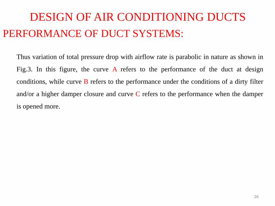
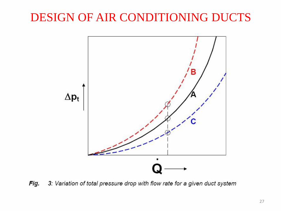
Thus variation of total pressure drop with airflow rate is parabolic in nature as shown in
Fig.3. In this figure, the curve A refers to the performance of the duct at design
conditions, while curve B refers to the performance under the conditions of a dirty filter
and/or a higher damper closure and curve C refers to the performance when the damper
is opened more.
PERFORMANCE OF DUCT SYSTEMS:
27
DESIGN OF AIR CONDITIONING DUCTS

28
DESIGN OF AIR CONDITIONING DUCTS
From the duct characteristic curve for constant resistance, one can write
)10(2
2
2
1
2,
1,
Q
Q
p
p
t
t
Thus knowing the total pressure drop and airflow rate at design condition (say 1),
one can obtain the total pressure drop at an off-design condition 2, using the above
equation.
PERFORMANCE OF DUCT SYSTEMS:
29
DESIGN OF AIR CONDITIONING DUCTS
SYSTEM BALANCING AND OPTIMIZATION:
In large buildings, after the Air Handling Unit is installed, it has to be balanced for
satisfactory performance. System balancing requires as a first step, measurements of actual
airflow rates at all supply air outlets and return air inlets. Then the dampers are adjusted so
that the actual measured flow rate corresponds to the specified flow rates. System
balancing may also require adjusting the fan speed to get required temperature drop across
the cooling or heating coils and required airflow rates in the conditioned zone. Balancing a
large air conditioning system can be a very expensive and time consuming method and
may require very accurate instruments for measuring air flow rates and temperatures.
However, system balancing is always recommended to get the full benefit from the total
cost incurred on air conditioning system.
30
DESIGN OF AIR CONDITIONING DUCTS
Large air conditioning systems require optimization of the duct design so as to
minimize the total cost, which includes the initial cost of the system and the lifetime
operating cost. At present very sophisticated commercial computer software are
available for optimizing the duct design. One such method is called as T-Method. The
reader should refer to advanced textbooks or ASHRAE handbooks for details on duct
optimization methods.
SYSTEM BALANCING AND OPTIMIZATION:

31
DESIGN OF AIR CONDITIONING DUCTS
Fans:
The fan is an essential and one of the most important components of almost all air
conditioning systems. Thus a basic understanding of fan performance characteristics is
essential in the design of air conditioning systems. The centrifugal fan is most
commonly used in air conditioning systems as it can efficiently move large quantities
of air over a large range of pressures. The centrifugal fan with forward-curved blades is
widely used in low-pressure air conditioning systems. The more efficient backward-
curved and airfoil type fans are used in large capacity, high-pressure systems.

32
DESIGN OF AIR CONDITIONING DUCTS Fans Laws:
The fan laws are a group of relations that are used to predict the effect of change of
operating parameters of the fan on its performance. The fan laws are valid for fans,
which are geometrically and dynamically similar. The fan laws have great practical use,
as it is not economically feasible to test fans of all sizes under all possible conditions.
The important operating parameters of a fan of fixed diameter are:
1. Density of air (ρ) which depends on its temperature and pressure
2. Operating speed of the fan (ω in rps), and
3. Size of the fan.
33
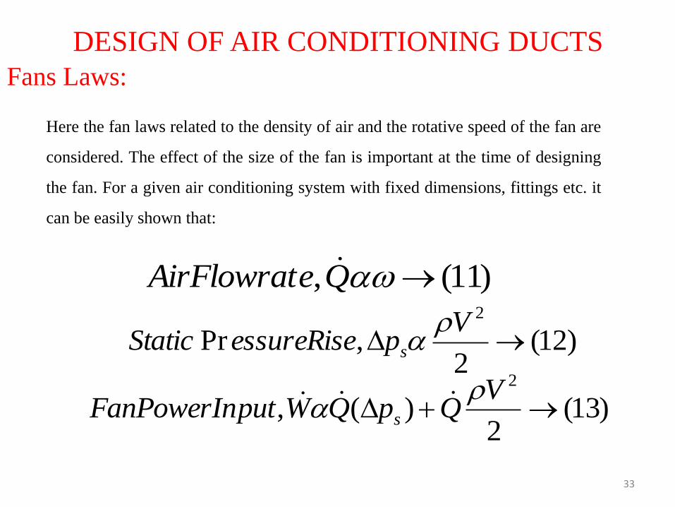
DESIGN OF AIR CONDITIONING DUCTS Fans Laws:
Here the fan laws related to the density of air and the rotative speed of the fan are
considered. The effect of the size of the fan is important at the time of designing
the fan. For a given air conditioning system with fixed dimensions, fittings etc. it
can be easily shown that:
)11(, QeAirFlowrat
)12(2
,Pr2
V
pessureRiseStatic s
)13(2
)(,2
V
QpQWputFanPowerIn s
34
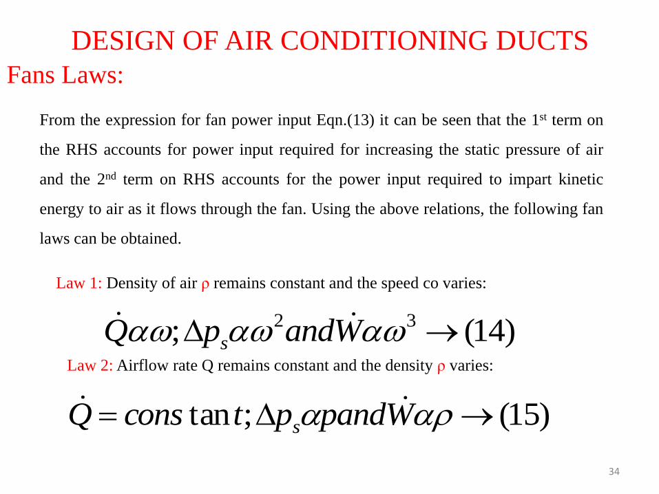
DESIGN OF AIR CONDITIONING DUCTS Fans Laws:
From the expression for fan power input Eqn.(13) it can be seen that the 1st term on
the RHS accounts for power input required for increasing the static pressure of air
and the 2nd term on RHS accounts for the power input required to impart kinetic
energy to air as it flows through the fan. Using the above relations, the following fan
laws can be obtained.
Law 1: Density of air ρ remains constant and the speed co varies:
)14(; 32 WandpQ s
Law 2: Airflow rate Q remains constant and the density ρ varies:
)15(;tan WpandptconsQ s
35
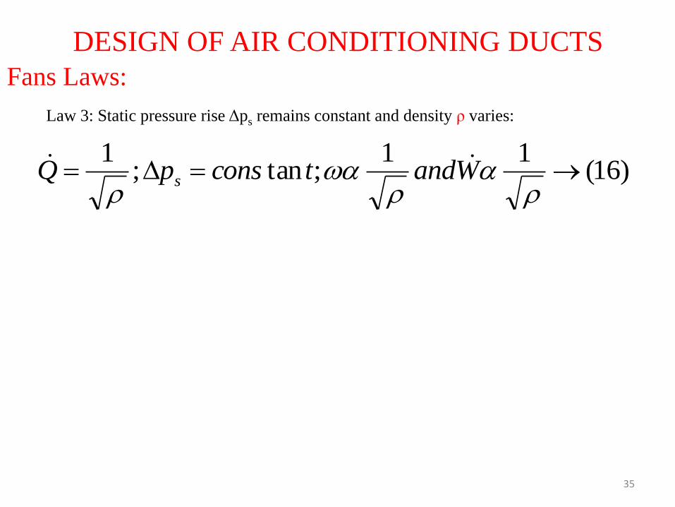
DESIGN OF AIR CONDITIONING DUCTS Fans Laws:
Law 3: Static pressure rise Δps remains constant and density ρ varies:
)16(11
;tan;1
WandtconspQ s
36
DESIGN OF AIR CONDITIONING DUCTS
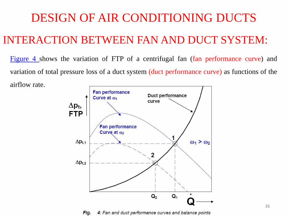
INTERACTION BETWEEN FAN AND DUCT SYSTEM:
Figure 4 shows the variation of FTP of a centrifugal fan (fan performance curve) and
variation of total pressure loss of a duct system (duct performance curve) as functions of the
airflow rate.
37
DESIGN OF AIR CONDITIONING DUCTS
INTERACTION BETWEEN FAN AND DUCT SYSTEM:
As shown in the figure, the point of intersection of the fan performance curve and the
duct performance curve yield the balance point for the combined performance of
fan and duct system. Point 1 gives a balance point between the fan and duct system
when the rotative speed of fan is ω1. At this condition the airflow rate is Q1 and the
total pressure loss which is equal to the FTP is Δpt,1. Now if the flow rate is reduced
to Q2, then the total pressure loss reduces to Δpt,2. To match the reduced flow rate and
the reduced pressure loss, the speed of the fan has to be reduced to ω2 or the position
of the inlet guide vanes of the centrifugal fan have to be adjusted to reduce the flow
rate. This will give rise to a new balance point at 2. Thus the fan and duct system
have to be matched when there is a change in the operating conditions.


![[O] cOmpaniessavarinocompanies.com/content/documents/bids... · hvac general notes hvac abbreviations hvac ductwork symbols hvac control symbols chaintreuil jensen stark architectural](https://img.pdfslide.us/doc/110x75/5ae5a13f7f8b9a29048c7dfa/o-compan-general-notes-hvac-abbreviations-hvac-ductwork-symbols-hvac-control-symbols.jpg)