Embed Size (px)
Citation preview

Honeywell
Application Manual
SmartVFD HVAC / SmartDrive HVAC
Variable Frequency Drivesfor Variable Torque Applications
FW0078V013
38-00002-01


Honeywell • 0
INDEXDocument: DPD01378A
Version release date: 9.12.13Corresponds to application version FW0078V013
1. Safety ..................................................................................................................31.1 Danger ............................................................................................................................ 31.2 Warnings......................................................................................................................... 41.3 Earthing and earth fault protection.................................................................................. 5
2. Startup wizard ....................................................................................................62.1 Using the startup wizard ................................................................................................. 62.2 PID mini-wizard............................................................................................................... 82.3 Pump and fan cascade mini-wizard ................................................................................ 92.4 Fire mode wizard ............................................................................................................ 92.5 Resonance sweep wizard ............................................................................................. 10
3. Keypad of the drive .........................................................................................133.1 Keypad with Advanced Commissioning Human Machine Interface (HMI).................... 143.1.1 Display unit ................................................................................................................... 143.1.2 Using the advanced commissioning HMI...................................................................... 143.2 Keypad with Multi-language Human Machine Interface (HMI)...................................... 203.2.1 Display unit ................................................................................................................... 203.2.2 Using the Multi-language Human Machine Interface .................................................... 213.3 Menu structure .............................................................................................................. 233.3.1 Quick setup ................................................................................................................... 243.3.2 Monitor .......................................................................................................................... 243.3.3 Parameters ................................................................................................................... 253.3.4 Diagnostics ................................................................................................................... 253.3.5 I/O and hardware .......................................................................................................... 283.3.6 User settings ................................................................................................................. 363.3.7 Favourites ..................................................................................................................... 37
4. Commissioning................................................................................................384.1 Specific functions of SmartVFD HVAC/SmartDrive HVAC ........................................... 384.2 Example of control connections .................................................................................... 394.3 Quick setup parameters................................................................................................ 414.4 Monitor group................................................................................................................ 434.4.1 Multimonitor view with advanced commissioning HMI.................................................. 434.4.2 Basic ............................................................................................................................. 434.4.3 Timer functions monitoring............................................................................................ 454.4.4 PID1 controller monitoring ............................................................................................ 454.4.5 PID2 controller monitoring ............................................................................................ 454.4.6 Multi-pump .................................................................................................................... 464.4.7 Maintenance timers....................................................................................................... 464.4.8 Fieldbus data monitoring............................................................................................... 464.4.9 Temperature inputs....................................................................................................... 474.5 Application parameters ................................................................................................. 484.5.1 Column explanations .................................................................................................... 494.5.2 Parameter programming ............................................................................................... 504.5.3 Group 3.1: Motor settings ............................................................................................. 544.5.4 Group 3.2: Start/Stop setup .......................................................................................... 574.5.5 Group 3.3: Control reference settings........................................................................... 584.5.6 Group 3.4: Ramp & Brakes Setup ................................................................................ 604.5.7 Group 3.5: I/O Configuration......................................................................................... 624.5.8 Group 3.6: Fieldbus Data Mapping ............................................................................... 69
Honeywell • 1
4.5.9 Group 3.7: Prohibit Frequencies ................................................................................... 704.5.10Group 3.8: Limit supervisions....................................................................................... 714.5.11Group 3.9: Protections ................................................................................................. 724.5.12Group 3.10: Automatic reset ........................................................................................ 754.5.13Group 3.11: Application Settings.................................................................................. 764.5.14Group 3.12: Timer functions......................................................................................... 774.5.15Group 3.13: PID-controller 1 ........................................................................................ 794.5.16Group 3.14: PID-controller 2 ........................................................................................ 854.5.17Group 3.15: Pump and Fan Cascade........................................................................... 874.5.18Group 3.16: Maintenance counters .............................................................................. 884.5.19Group 3.17: Fire mode ................................................................................................. 894.5.20User levels.................................................................................................................... 904.6 HVAC Application - Additional parameter information .................................................. 914.7 Fault tracing ................................................................................................................ 1264.7.1 Fault appears .............................................................................................................. 1264.7.2 Fault history ................................................................................................................ 1274.7.3 Fault codes ................................................................................................................. 128
Safety Honeywell • 2
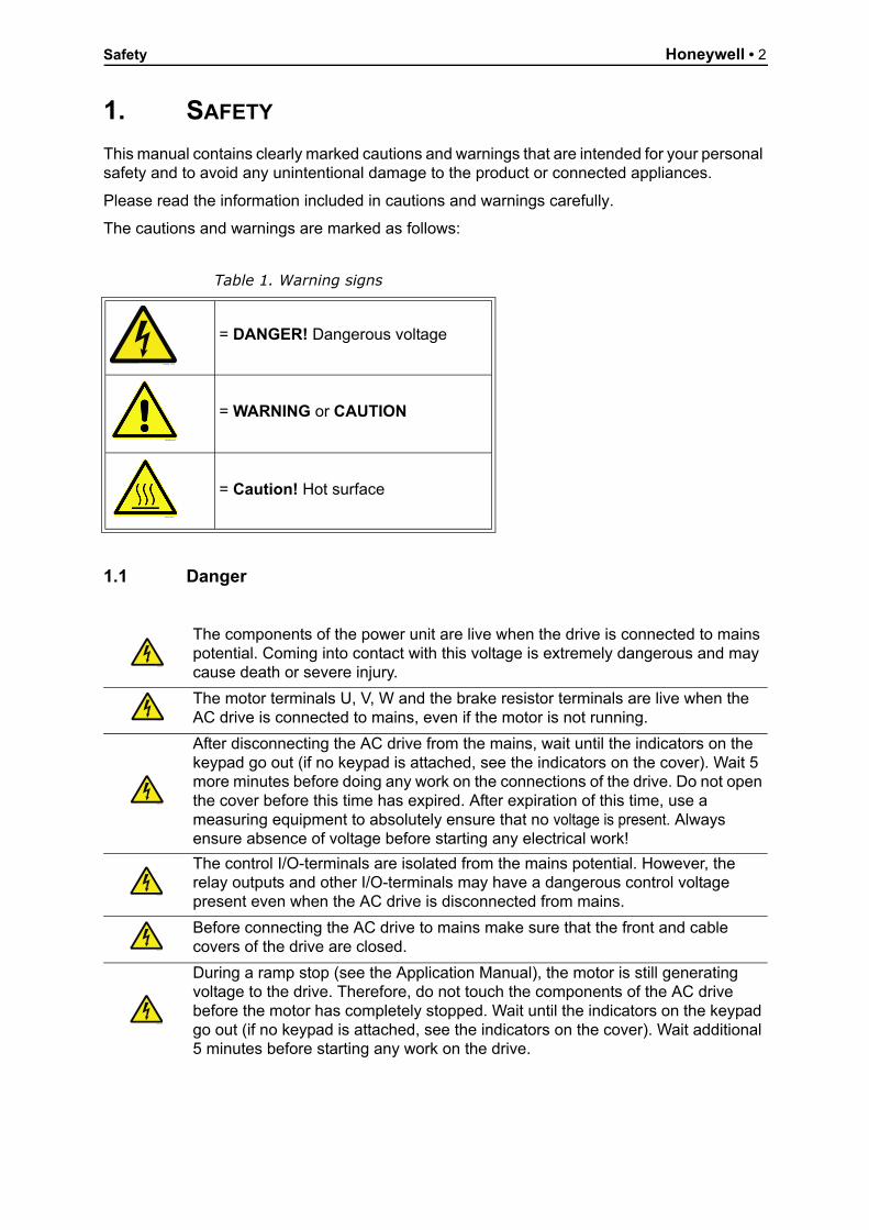
1. SAFETY
This manual contains clearly marked cautions and warnings that are intended for your personal safety and to avoid any unintentional damage to the product or connected appliances.
Please read the information included in cautions and warnings carefully.
The cautions and warnings are marked as follows:
1.1 Danger
Table 1. Warning signs
= DANGER! Dangerous voltage
= WARNING or CAUTION
= Caution! Hot surface
The components of the power unit are live when the drive is connected to mains potential. Coming into contact with this voltage is extremely dangerous and may cause death or severe injury.
The motor terminals U, V, W and the brake resistor terminals are live when the AC drive is connected to mains, even if the motor is not running.
After disconnecting the AC drive from the mains, wait until the indicators on the keypad go out (if no keypad is attached, see the indicators on the cover). Wait 5 more minutes before doing any work on the connections of the drive. Do not open the cover before this time has expired. After expiration of this time, use a measuring equipment to absolutely ensure that no voltage is present. Always ensure absence of voltage before starting any electrical work!
The control I/O-terminals are isolated from the mains potential. However, the relay outputs and other I/O-terminals may have a dangerous control voltage present even when the AC drive is disconnected from mains.
Before connecting the AC drive to mains make sure that the front and cable covers of the drive are closed.
During a ramp stop (see the Application Manual), the motor is still generating voltage to the drive. Therefore, do not touch the components of the AC drive before the motor has completely stopped. Wait until the indicators on the keypad go out (if no keypad is attached, see the indicators on the cover). Wait additional 5 minutes before starting any work on the drive.
9000 emf
13006.emf
9001.emf
9000.emf
9000.emf
9000.emf
9000.emf
9000.emf
9000.emf

Honeywell • 3 Safety
1.2 Warnings
The AC drive is meant for fixed installations only.
Do not perform any measurements when the AC drive is connected to the mains.
The earth leakage current of the AC drives exceeds 3.5mA AC. According to standard EN61800-5-1, a reinforced protective ground connection must be ensured. See Chapter 1.3.
If the AC drive is used as a part of a machine, the machine manufacturer is responsible for providing the machine with a supply disconnecting device (EN 60204-1).
Only spare parts delivered by Vacon can be used.
At power-up, power brake or fault reset the motor will start immediately if the start signal is active, unless the pulse control for Start/Stop logic has been selected.Futhermore, the I/O functionalities (including start inputs) may change if parameters, applications or software are changed. Disconnect, therefore, the motor if an unexpected start can cause danger.
The motor starts automatically after automatic fault reset if the auto restart function is activated. See the Application Manual for more detailed information.
Prior to measurements on the motor or the motor cable, disconnect the motor cable from the AC drive.
Do not touch the components on the circuit boards. Static voltage discharge may damage the components.
Check that the EMC level of the AC drive corresponds to the requirements of your supply network.
13006.emf
13006.emf
13006.emf
13006.emf
13006.emf
13006.emf
13006.emf
13006.emf
13006.emf
13006.emf

Safety Honeywell • 4
1.3 Earthing and earth fault protection
The AC drive must always be earthed with an earthing conductor connected to the earthing terminal marked with .
The earth leakage current of the drive exceeds 3.5mA AC. According to EN61800-5-1, one or more of the following conditions for the associated protective circuit must be satisfied:
a) The protective conductor must have a cross-sectional area of at least 10 mm2 Cu or 16 mm2 Al, through its total run.
b) Where the protective conductor has a cross-sectional area of less than 10 mm2 Cu or 16 mm2 Al, a second protective conductor of at least the same cross-sectional area must be provided up to a point where the protective conductor has a cross-sectional area not less than 10 mm2 Cu or 16 mm2 Al.
c) Automatic disconnection of the supply in case of loss of continuity of the protective conductor.
The cross-sectional area of every protective earthing conductor which does not form part of the supply cable or cable enclosure must, in any case, be not less than:
- 2.5mm2 if mechanical protection is provided or- 4mm2 if mechanical protection is not provided.
The earth fault protection inside the AC drive protects only the drive itself against earth faults in the motor or the motor cable. It is not intended for personal safety.
Due to the high capacitive currents present in the AC drive, fault current protective switches may not function properly.
NOTE! You can download the English and French product manuals with applicable safety, warning and caution information from https://customer.honeywell.com/en-US/Pages/de-fault.aspx.
REMARQUE Vous pouvez télécharger les versions anglaise et française des manuels produit contenant l’ensemble des informations de sécurité, avertissements et mises en garde applica-bles sur le site https://customer.honeywell.com/en-US/Pages/default.aspx.
CAUTION!
Do not perform any voltage withstand tests on any part of the AC drive. There is a certain procedure according to which the tests must be performed. Ignoring this procedure can cause damage to the product.
13006.emf
13006.emf

Honeywell • 5 STARTUP WIZARD
2. STARTUP WIZARD
2.1 Using the startup wizard
In the Startup Wizard, you will be prompted for essential information needed by the drive so that it can start controlling your process. In the Wizard, you will need the following keypad buttons:
Left/Right arrows. Use these to easily move between digits and decimals.
Up/Down arrows. Use these to move between options in menu and to change value.
OK button. Confirm selection with this button.
Back/Reset button. Pressing this button, you can return to the previous question in the Wizard. If pressed at the first question, the Startup Wizard will be cancelled.
Once you have connected power to the drive, follow these instructions to easily set up your drive.
NOTE: You can have your drive equipped with either an advanced commissioning keypad or a text keypad. In the following examples, image of the advanced commissioning keypad is on the left, LCD keypad on the right.
Push the OK button unless you want to set all parameter values manually.
1 Language selection varies according to the installed language package
2Daylight saving Russia
USEUOFF
3 Time hh:mm:ss
4 Day mm.dd.
5 Year yyyy
6 Run Startup Wizard? YesNo
BACKRESET

STARTUP WIZARD Honeywell • 6
Parameters affected:
Ramp table for fan setup:
Now the Startup Wizard is completed.
The Startup Wizard can be re-initiated by activating the parameter Restore factory defaults (par. P6.5.1) in the Parameter backup submenu (M6.5).
NOTE: Neigher parameter Restore factory defaults (par. P6.5.1) nor the Startup Wizard will work if there is an external RUN command on the I/O!
7 Choose your process PumpFan
P3.4.2 P3.4.3 P3.2.4 P3.2.5 P3.4.8 P3.4.10 P3.3.1 P3.1.2.7
Pump 5.0 5.0 1 1 False 60.0 20.0 Untouched
Fan Fromtable
Fromtable
1 0 True 120.0 20.0 1
P3.4.2 Acceleration Time
P3.4.3 Deceleration Time
P3.2.4 Start Function
P3.2.5 Stop Function
P3.4.8 RampTimeOptimizerEnable
P3.4.10 RampTimeOptimizerMaxLimit
P3.3.1 MinFrequency
P3.1.2.7 U/F Ratio
Ramp times
400 V / 480 V 230 V
20 s 400-1P1 - 400-7P5 / C 0015 – C 0100 230-P55 - 230-4P0 / A 0007 – A 0050
30 s 400-11P - 400-22P / C 0150 – C 0300 230-5P5 - 230-11P / A 0075 – A 0150
45 s 400-30P - 400-55P / C 0400 – C 0750 230-15P - 230-30P / A 0200 – A 0400
60 s 400-75P - 400-90P / C 1000 – C 1250 230-37P - 230-45P / A 0500 – A 0750
90 s 400-110 - 400-160 / C 1500 – C 2500 230-55P / A 1000 – A 1250
8 Set value for Motor Nominal Speed (according to nameplate)
Range: 24...19,200 rpm
9 Set value for Motor Nominal Current (according to nameplate)
Range: Varies
2

Honeywell • 7 STARTUP WIZARD
2.2 PID mini-wizard
The PID Mini Wizard can be initiated by choosing Activate for parameter P1.18 in the Quick setup menu. This wizard presupposes that you are going to use the PID controller in the "one feedback / one setpoint" mode. The control place will be I/O A and the default process unit ‘%’.
The PID mini wizard asks for the following values to be set:
If any other process unit than ‘%’ is selected the following questions appear:
If not the Wizard will directly jump to step 5.
If one of the analogue input signals is selected the question 6 appears. Otherwise you will be taken to question 7.
If one of the analogue input signals is selected the question 9 appears. Otherwise you will be taken to question 11.If either of the options Keypad Setpoint 1 or 2 is chosen the question 10 will appear.
If option ‘Yes’ is selected you will be prompted for three more values:
1 Process unit selection(Several selections. See par. P3.13.1.4)
2 Process unit min
3 Process unit max
4 Process unit decimals 0...4
5 Feedback 1 source selection See par. P3.13.2.4.
6 Analogue input signal range0 = 0…10V / 0…20mA1 = 2…10V / 4…20mASee par. P3.5.2.3.
7 Error inversion0 = Normal1 = Inverted
8 Setpoint source selection See par. P3.13.2.4 for selections.
9 Analogue input signal range0 = 0…10V / 0…20mA1 = 2…10V / 4…20mASee par. P3.5.2.3.
10 Keypad setpoint
11 Sleep function?NoYes
12Sleep frequency limit 1 P3.13.2.8 Sleep delay 1 P3.13.2.9 Wake-up level 1
0.00...320.00 Hz

STARTUP WIZARD Honeywell • 8
2.3 Pump and fan cascade mini-wizard
The PFC mini-wizard asks the most important questions for setting up a PFC system. The PID mini-wizard always precedes the PFC mini-wizard. The keypad will guide you through the questions as in chapter 2.2 then to be followed by the set of questions below:
If Autochange function is enabled the following three questions will appear. If Autochange will not be used the Wizard jumps directly to question 21.
After this, the keypad will show the digital input and relay output configuration recommended by the application (Advanced commissioning keypad only). Write these values down for future reference.
2.4 Fire mode wizard
NOTE! THE WARRANTY IS VOID, IF THE FIRE MODE FUNCTION IS ACTIVATED.
Test Mode can be used to test the Fire Mode function without voiding the warranty.
Fire Mode Wizard is intended for easy commissioning of the Fire Mode function. The Fire Mode Wizard can be initiated by choosing Activate for parameter 1.1.2 in the Quick setup menu.
13 Sleep delay 1 0...3000 s
14 Wake-up level 1Range depends on selected pro-cess unit.
15 Number of motors 1...5
16 Interlock function0 = Not used1 = Enabled
17 Autochange0 = Disabled1 = Enabled
18 Include FC0 = Disabled1 = Enabled
19 Autochange interval 0.0...3000.0 h
20 Autochange: Frequency limit 0.00...50.00 Hz
21 Bandwidth 0...100%
22 Bandwidth delay 0...3600 s
1 Fire Mode frequency source (P3.17.2)
Several selections, see chapter 4.17.
2

Honeywell • 9 STARTUP WIZARD
If any other source than ‘Fire mode frequency’ is selected the wizard will jump directly to question 3.
2.5 Resonance sweep wizard
Initiating the resonance sweep function
1. Locate parameter P3.7.9 and press OK.
2. Select value 1 ‘Activate’ with the arrow buttons and press OK.
3. With text ‘Start sweep’ on the display, press the Start button. Sweeping starts.
4. Press the OK button every time the resonance stops in order to tag where the range starts and ends.
5. After successful sweeping you will be prompted to save. If yes, press OK.
6. If the Resonance sweeping function was succesfully completed text ‘Successful’ appears on the display. Then press OK and the display will return to the parameter P3.7.9 display with value ‘Inactive’.
2 Fire Mode frequency (P3.17.3) 8.00 Hz...MaxFreqRef (P3.3.1.2)
3 Signal activation?
Should the signal activate on opening or closing contact?0 = Open contact1 = Closed contact
4Fire Mode activation on OPEN (P3.17.4)/Fire Mode activation on CLOSE(P3.17.5)
Choose the digital input to activate Fire mode. See also chapter 8.13.
5 Fire Mode reverse (P3.17.6)
Choose the digital input to activate the reverse direction in Fire mode. DigIn Slot0.1 = Always direction FORWARDDigIn Slot0.2 = Always direction REVERSE
6 Fire Mode password (P3.17.1)
Choose password to enable the Fire Mode function.1234 = Enable Test mode1002 = Enable Fire Mode

STARTUP WIZARD Honeywell • 10
Figure 1. Resonance sweep
�
Pressto tag resonance ranges
2

Honeywell • 11 KEYPAD OF THE DRIVE
3. KEYPAD OF THE DRIVE
The control keypad is the interface between the drive and the user. With the control keypad it is possible to control the speed of a motor, to supervise the state of the equipment and to set the frequency converter's parameters.
There are two keypad types you can choose for your user interface: keypad with an advanced commissioning Human Machine Interface (HMI) and keypad with a Multi-language Human Ma-chine Interface (HMI).
The button section of the keypad is identical for both keypad types.
Figure 2. Keypad buttons
Scroll menu upIncrease value
Scroll menu downDecrease value
thgirrosrucevoMtfelrosrucevoM
Move backward in menuExit edit modeReset faults with long press
Change control place
nottubtratSnottubpotS
Enter active level/itemConfirm selection
OK7078.emf

KEYPAD OF THE DRIVE Honeywell • 12
3.1 Keypad with Advanced Commissioning Human Machine Interface (HMI)
The advanced commissioning Human Machine Interface (HMI) features a graphical LCD dis-play and 9 buttons with an integrated copy function for parameters.
3.1.1 Display unit
The display unit indicates the status of the motor and the drive and any irregularities in motor or drive functions. On the display, the user sees information about his present location in the menu structure and the item displayed. If the text on the text line is too long to fit in the display, the text will scroll from left to right to reveal the whole text string.
3.1.1.1 Main menu
The data on the control keypad are arranged in menus and submenus. Use the Up and Down arrows to move between the menus. Enter the group/item by pressing the OK button and return to the former level by pressing the Back/Reset button.
The Location field indicates your current location. The Status field gives information about the present status of the drive. See Figure 3.
Figure 3. Main menu
3.1.2 Using the advanced commissioning HMI
3.1.2.1 Editing values
Change value of a parameter following the procedure below:
7. Locate the parameter.
8. Press OK to enter the Edit mode.
9. Set new value with the arrow buttons up/down. You can also move from digit to digit with the arrow buttons left/right if the value is numerical and change then the value with the arrow buttons up/down.
10. Confirm change with OK button or ignore change by returning to previous level with Back/Reset button.
9159.emf
Main Menu
Quick Setup( 17 )
Parameters
( 12 )
STOP READY I/O
ID: M1
( 5 )Monitor
Status fieldSTOP/RUN
Direction ALARM
Status fieldREADY/NOT READY/FAULT
Control place:PC/IO/KEYPAD/FIELDBUS
Activated group/item:Press OK to enter
Number of itemsin the group
Location field(Parameter ID number andcurrent menu location

Honeywell • 13 KEYPAD OF THE DRIVE
Figure 4. Editing values on advanced commissioning HMI
3.1.2.2 Resetting fault
Instructions for how to reset a fault can be found in chapter 4.7.1 on page 125.
3.1.2.3 Local/remote control button
The LOC/REM button is used for two functions: to quickly access the Control page and to easily change between the Local (Keypad) and Remote control places.
Control places
The control place is the source of control where the drive can be started and stopped. Every control place has its own parameter for selecting the frequency reference source. In the HVAC drive, the Local control place is always the keypad.The Remote control place is determined by parameter P1.15 (I/O or Fieldbus). The selected control place can be seen on the status bar of the keypad.
Remote control place
I/O A, I/O B and Fieldbus can be used as remote control places. I/O A and Fieldbus have thelowest priority and can be chosen with parameter P3.2.1 (Rem Control Place). I/O B, again, can bypass the remote control place selected with parameter P3.2.1 using a digital input. The digital input is selected with parameter P3.5.1.5 (I/O B Ctrl Force).
Local control
Keypad is always used as control place while in local control. Local control has higher prioritythan remote control. Therefore, if, for example, bypassed by parameter P3.5.1.5 through digital input while in Remote, the control place will still switch to Keypad if Local is selected. Switching between Local and Remote Control can be done by pressing the Loc/Rem-button on the keypad or by using the "Local/Remote" (ID211) parameter.
�STOP READY I/O
ID:172 M3.2.1 �STOP READY I/O
ID: M3.2.1 �STOP READY I/O
M3.2.1
�STOP READY I/O
ID:172 M3.2.1 �STOP READY I/O
M3.2.1
9435_uk
OK OK
OK
LOCREM
OR:
Start/Stop Setup
Rem Control PlaceI/O Control
KeypadStopButtonYes
Start FunctionRamping
Edit
Help
Add to favorites
Rem Control Place Rem Control Place
I/O Control
FieldbusCTRL
Start/Stop Setup
Rem Control PlaceI/O Control
KeypadStopButtonYes
Start FunctionRamping
Rem Control Place
I/O Control
FieldbusCTRL
KEYPAD OF THE DRIVE Honeywell • 14
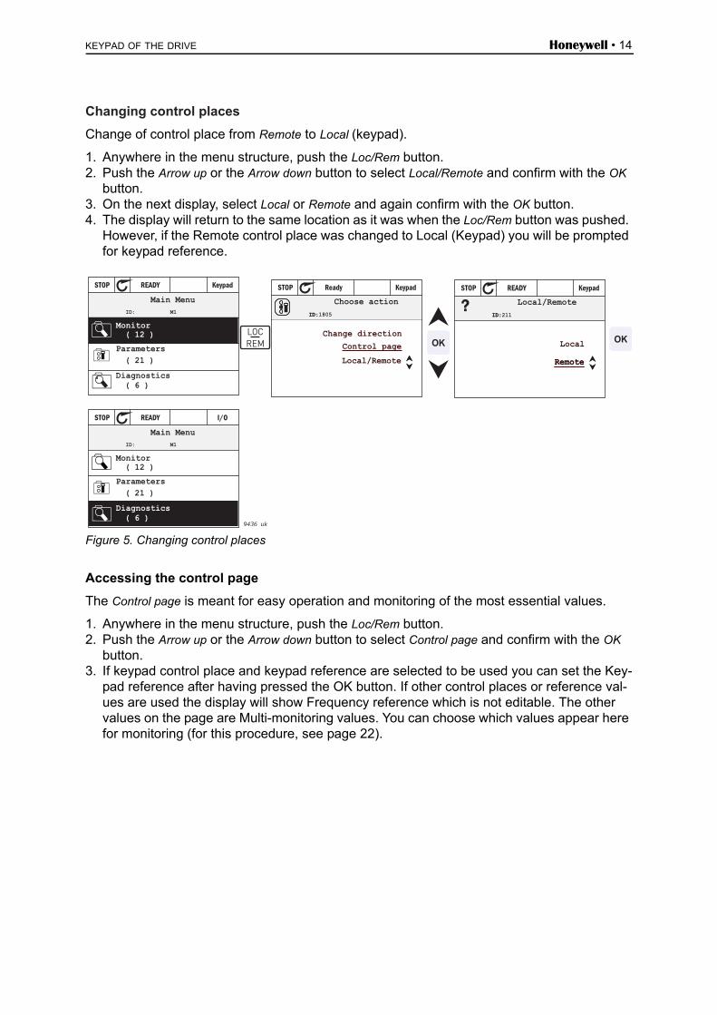
Changing control places
Change of control place from Remote to Local (keypad).
1. Anywhere in the menu structure, push the Loc/Rem button.2. Push the Arrow up or the Arrow down button to select Local/Remote and confirm with the OK
button.3. On the next display, select Local or Remote and again confirm with the OK button.4. The display will return to the same location as it was when the Loc/Rem button was pushed.
However, if the Remote control place was changed to Local (Keypad) you will be prompted for keypad reference.
Figure 5. Changing control places
Accessing the control page
The Control page is meant for easy operation and monitoring of the most essential values.
1. Anywhere in the menu structure, push the Loc/Rem button.2. Push the Arrow up or the Arrow down button to select Control page and confirm with the OK
button.3. If keypad control place and keypad reference are selected to be used you can set the Key-
pad reference after having pressed the OK button. If other control places or reference val-ues are used the display will show Frequency reference which is not editable. The other values on the page are Multi-monitoring values. You can choose which values appear here for monitoring (for this procedure, see page 22).
( 21 )�
�
STOP READY Keypad
ID: M1
( 12 )�
( 6 )
ID:
STOP Ready Keypad
ID:1805?
ID:
STOP READY Keypad
ID:211
( 21 )�
�
STOP READY I/O
ID: M1
( 12 )�
( 6 )9436 uk
LOCREM OK OK
Remote
Main Menu
Parameters
Diagnostics
Monitor
Choose action
Local/Remote
Control pageChange direction
Local/Remote
Remote
Local
Main Menu
Parameters
Diagnostics
Monitor

Honeywell • 15 KEYPAD OF THE DRIVE
Figure 6. Accessing Control page
3.1.2.4 Help texts
The advanced commissioning HMI features instant help and information displays for various items. All parameters offer an instant help display. Select Help and press the OK button.
Text information is also available for faults, alarms and the startup wizard.
Figure 7. Help text example
3.1.2.5 Adding item to favourites
You might need to refer to certain parameter values or other items often. Instead of locating them one by one in the menu structure, you may want to add them to a folder called Favourites where they can easily be reached.
To remove an item from the Favourites, see chapter 3.3.7.
Figure 8. Adding item to Favourites
( 15 )�
�
STOP READY I/O
ID: M1
( 7 )�
( 6 )
ID:
STOP Ready Keypad
ID:1805
STOP READY Keypad
( 6 )
0.00 Hz
0.00Hz
0.00A
0.00%
0.00%
ID:184
0.00 Hz
0.00Hz
0.00A
0.00%
0.00%
STOP READY Keypad
( 6 )
ID:168
0.00 Hz
0.00Hz
0.00A
0.00%
0.00% 9437_uk
OK
OK
Keypad ReferenceMain Menu
Parameters
Diagnostics
Monitor
Choose action
Local/Remote
Control pageChange direction
Output Frequency
Motor Current
Motor Torque
Motor Power
Keypad Reference
Output Frequency
Motor Current
Motor Torque
Motor Power
LOCREM OK
( 6 )
STOP READY I/O
ID:403 P3.5.1.1
( 6 )
STOP READY I/O
ID:403 P3.5.1.1
STOP READY I/O
ID:403 P3.5.1.1
9165
.em
f
OK OK
Digital Inputs
Ctrl Signal 1 A
Ctrl Signal 1 B
Ctrl Signal 2 A
Add to favorites
Ctrl signal 1 A
Edit
Help
Start Signal 1 for control PlaceI/O A. Start Signal 1functionality chosen with I/O ALogic in Start/Stop Setup Menu.
Ctrl signal 1 A
Basic Settings
Motor Nom Voltg230.00 V
Motor Nom Speed
1430 rpm
STOP READY I/O
Motor Nom Freq50.00 Hz
Edit
Help
Motor Nom Freq
STOP READY I/O
Add to favorites
Motor Nom Freq
was added tofavorites. Press OKto continue.
STOP READY I/O
9166
.em
f
OK OK

KEYPAD OF THE DRIVE Honeywell • 16
3.1.2.6 Copying parameters
NOTE: This feature is available in Advanced commissioning HMI only.
The parameter copy function can be used to copy parameters from one drive to another.
The parameters are first saved to the keypad, then the keypad is detached and connected toanother drive. Finally the parameters are downloaded to the new drive restoring them from the keypad.Before any parameters can successfully be copied from one drive to another the drive has tobe stopped when the parameters are downloaded.First go into User settings menu and locate the Parameter backup submenu. In the Parameter backup submenu, there are three possible functions to be selected: Restore factory defaults will re-establish the parameter settings originally made at the factory.By selecting Save to keypad you can copy all parameters to the keypad. Restore from keypad will copy all parameters from keypad to a drive.
Figure 9. Copying parameters
NOTE: If the keypad is changed between drives of different sizes, the copied values of theseparameters will not be used:
Motor nominal current (P3.1.1.4)Motor nominal voltage (P3.1.1.1)Motor nominal speed (P3.1.1.3)Motor nominal power (P3.1.1.6)Motor nominal frequency (P3.1.1.2)Motor cos phii (P3.1.1.5)Switching frequency (P3.1.2.1)Motor current limit (P3.1.1.7)Stall current limit (P3.9.12)Stall time limit (P3.9.13)Stall frequency (P3.9.14)
Maximum frequency (P3.3.2)
3.1.2.7 Multi-monitor
NOTE: This feature is available in Advanced commissioning HMI only.
On the multi-monitor page, you can collect nine values that you wish to monitor.
STOP READY Keypad
Main Menu
Favourites( 0 )
( 4 )
ID: M6
User settings
I/O and Hardware( 8 ) OK
STOP READY Keypad
Drive name
( 3 )
ID:
User settings
Application selectionHVAC
5.6M 5.6M
Parameter backup
Drive
STOP READY Keypad
Restore from keypad
ID:
Restore factory defaults
1.5.6M 5.6M
Save to keypad
Parameter backup
OK
7079.emf
Honeywell • 17 KEYPAD OF THE DRIVE
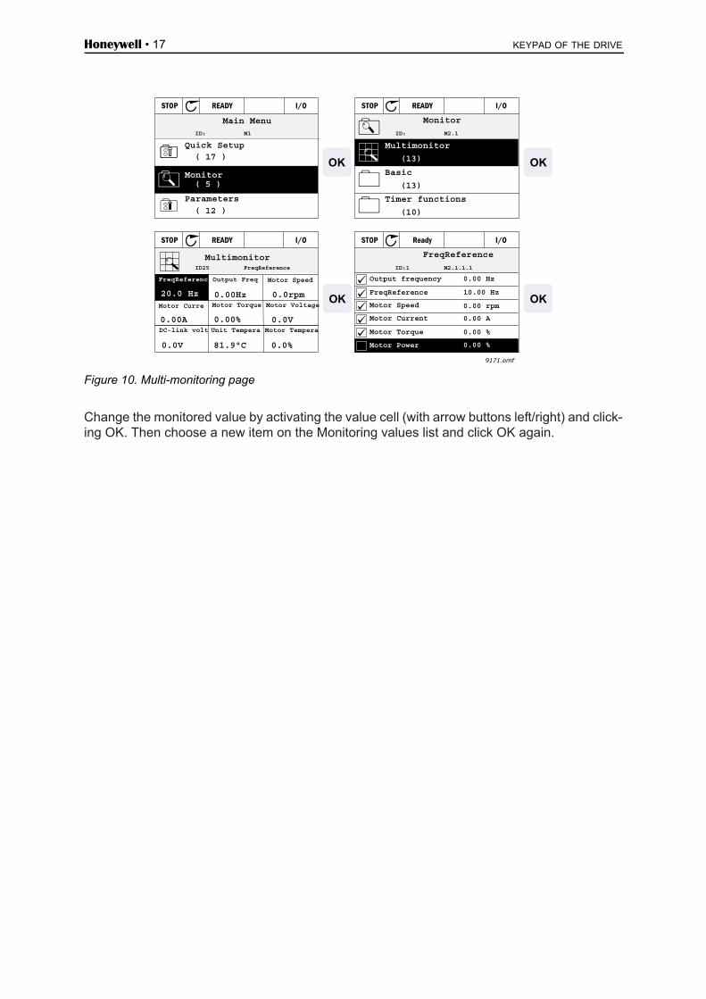
Figure 10. Multi-monitoring page
Change the monitored value by activating the value cell (with arrow buttons left/right) and click-ing OK. Then choose a new item on the Monitoring values list and click OK again.
Main Menu
Quick Setup( 17 )
Parameters
( 12 )
ID: M1
STOP READY I/O
( 5 )Monitor
Monitor
Multimonitor
(13)
Basic
(13)
Timer functions
(10)
STOP READY I/O
ID: M2.1
0.0rpm
STOP READY I/O
Multimonitor
0.00 HzID25 FreqReference
Output Freq
0.00HzMotor Curre
0.00A
Motor Torque
0.00%
Motor Voltage
Motor Speed
Motor TemperaUnit TemperaDC-link volt
20.0 Hz
FreqReferenc
0.0V
0.0V 81.9°C 0.0%
ID:1 M2.1.1.1
STOP Ready I/O
FreqReference
Output frequency
Motor Power
FreqReference
Motor Speed
Motor Current
Motor Torque
0.00 Hz
10.00 Hz
0.00 rpm
0.00 A
0.00 %
0.00 %
9171.emf
OK OK
OKOK

KEYPAD OF THE DRIVE Honeywell • 18
3.2 Keypad with Multi-language Human Machine Interface (HMI)
You can also choose a Keypad with Multi-language Human Machine Interface (HMI) for your user interface. It has mainly the same functionalities as the keypad with advanced commission-ing HMI although some of these are somewhat limited.
3.2.1 Display unit
The display unit indicates the status of the motor and the drive and any irregularities in motor or drive functions. On the display, the user sees information about his present location in the menu structure and the item displayed. If the text on the text line is too long to fit in the display, the text will scroll from left to right to reveal the whole text string.
3.2.1.1 Main menu
The data on the control keypad are arranged in menus and submenus. Use the Up and Down arrows to move between the menus. Enter the group/item by pressing the OK button and return to the former level by pressing the Back/Reset button.
9167
.em
f
Indicators: Status
Indicators: Alarm, Fault
Indicators: Direction
Indicators: Control place
Group or parameter name
Menu location

Honeywell • 19 KEYPAD OF THE DRIVE
3.2.2 Using the Multi-language Human Machine Interface
3.2.2.1 Editing values
Change value of a parameter following the procedure below:
1. Locate the parameter.
2. Enter the Edit mode by pressing OK.
3. Set new value with the arrow buttons up/down. You can also move from digit to digit with the arrow buttons left/right if the value is numerical and change then the value with the arrow buttons up/down.
4. Confirm change with OK button or ignore change by returning to previous level with Back/Reset button.
Figure 11. Editing values
3.2.2.2 Resetting fault
Instructions for how to reset a fault can be found in chapter 4.7.1 on page 125.
3.2.2.3 Local/remote control button
The LOC/REM button is used for two functions: to quickly access the Control page and to easily change between the Local (Keypad) and Remote control places.
Control places
The control place is the source of control where the drive can be started and stopped. Every control place has its own parameter for selecting the frequency reference source. In the HVAC drive, the Local control place is always the keypad.The Remote control place is determined by parameter P1.15 (I/O or Fieldbus). The selected control place can be seen on the status bar of the keypad.
Remote control place
I/O A, I/O B and Fieldbus can be used as remote control places. I/O A and Fieldbus have thelowest priority and can be chosen with parameter P3.2.1 (Rem Control Place). I/O B, again, can bypass the remote control place selected with parameter P3.2.1 using a digital input. The digital input is selected with parameter P3.5.1.5 (I/O B Ctrl Force).
Local control
Keypad is always used as control place while in local control. Local control has higher prioritythan remote control. Therefore, if, for example, bypassed by parameter P3.5.1.5 through digital input while in Remote, the control place will still switch to Keypad if Local is selected. Switching between Local and Remote Control can be done by pressing the Loc/Rem-button on the keypad or by using the "Local/Remote" (ID211) parameter.
9168.emf
BACKRESET

KEYPAD OF THE DRIVE Honeywell • 20
Changing control places
Change of control place from Remote to Local (keypad).
1. Anywhere in the menu structure, push the Loc/Rem button.
2. Using the arrow buttons, select Local/Remote and confirm with the OK button.
3. On the next display, select Local or Remote and again confirm with the OK button.
4. The display will return to the same location as it was when the Loc/Rem button was pushed. However, if the Remote control place was changed to Local (Keypad) you will be prompted for keypad reference.
Figure 12. Changing control places
Accessing the control page
The Control page is meant for easy operation and monitoring of the most essential values.
1. Anywhere in the menu structure, push the Loc/Rem button.
2. Push the Arrow up or the Arrow down button to select Control page and confirm with the OK button.
3. The control page appears If keypad control place and keypad reference are selected to be used you can set the Key-pad reference after having pressed the OK button. If other control places or reference val-ues are used the display will show Frequency reference which is not editable.
Figure 13. Accessing Control page
9438_uk
LOCREM OK OK
9170A_uk
OKOK
LOCREM

Honeywell • 21 KEYPAD OF THE DRIVE
3.3 Menu structure
The basic menu structure is depicted in Figure 14. The menu structure is referenced by its in-dex. The HMI contains the same indices as the PC tool. The indices contain a letter indicating the type of information. Those vary slightly between HMI and PC-tool:
• Px.x.x: Parameter• Vx.x.x: Monitored value (only in HMI)• Mx.x.x: Monitored value (only in PC-tool)• Mx.x: Menu with several values/parameters below (only in HMI)
Figure 14.Basic menu structure as shown in pc-tool

KEYPAD OF THE DRIVE Honeywell • 22
3.3.1 Quick setup
The Quick Setup Menu includes the minimum set of most commonly used parameters during installation and commissioning. More detailed information on the parameters of this group you will find in chapter 4.3.
3.3.2 Monitor
Multi-monitor
NOTE: This menu is not available in Multi-language HMI.
On the multi-monitor page, you can collect nine values that you wish to monitor. See chapter 4.4
Figure 15. Multi-monitoring page
Change the monitored value by activating the value cell (with arrow buttons left/right) and click-ing OK. Then choose a new item on the Monitoring values list and click OK again.
Basic
The basic monitoring values are the actual values of selected parameters and signals as well as statuses and measurements.
Timer functions
Monitoring of timer functions and the Real Time Clock. See chapter 4.4.3.
PID Controller 1
Monitoring of PID controller values. See chapters 4.4.4 and 4.4.5.
PID Controller 2
Monitoring of PID controller values. See chapters 4.4.4 and 4.4.5.
Multi-pump
Monitoring of values related to the use of several drives. See chapter 4.4.6.
Fieldbus data
Fieldbus data shown as monitor values for debugging purposes at e.g. fieldbus commissioning. See chapter 4.4.8.
Main Menu
Quick Setup( 17 )
Parameters
( 12 )
ID: M1
STOP READY I/O
( 5 )Monitor
Monitor
Multimonitor
(13)
Basic
(13)
Timer functions
(10)
STOP READY I/O
ID: M2.1
0.0rpm
STOP READY I/O
Multimonitor
0.00 HzID25 FreqReference
Output Freq
0.00HzMotor Curre
0.00A
Motor Torque
0.00%
Motor Voltage
Motor Speed
Motor TemperaUnit TemperaDC-link volt
20.0 Hz
FreqReferenc
0.0V
0.0V 81.9°C 0.0%
ID:1 M2.1.1.1
STOP Ready I/O
FreqReference
Output frequency
Motor Power
FreqReference
Motor Speed
Motor Current
Motor Torque
0.00 Hz
10.00 Hz
0.00 rpm
0.00 A
0.00 %
0.00 %
9171.emf
OK OK
OKOK

Honeywell • 23 KEYPAD OF THE DRIVE
3.3.3 Parameters
Through this submenu, you can reach the application parameter groups and parameters. More information on parameters in chapter 4.
3.3.4 Diagnostics
Under this menu, you can find Active faults, Reset faults, Fault history, Counters and Software info.
3.3.4.1 Active faults
3.3.4.2 Reset faults
3.3.4.3 Fault history
3.3.4.4 Total counters*
Menu Function Note
Active faults When a fault/faults appear(s), the display with the name of the fault starts to blink. Press OK to return to the Diagnostics menu. The Active faults submenu shows the number of faults. Select the fault and push OK to see the fault-time data.
The fault remains active until it is cleared with the Reset button (push for 2 s) or with a reset signal from the I/O terminal or fieldbus or by choos-ing Reset faults (see below).The memory of active faults can store the maximum of 10 faults in the order of appearance.
Menu Function Note
Reset faults In this menu you can reset faults. For closer instructions, see chapter 4.7.1.
CAUTION! Remove external Control signal before resetting the fault to prevent unintentional restart of the drive.
Menu Function Note
Fault history 40 latest faults are stored in the Fault history.
Entering the Fault history and click-ing OK on the selected fault shows the fault time data (details).
Index Parameter Min Max Unit Default ID Description
V4.4.1 Energy counter Varies 2291
Amount of energy taken from supply network. No reset.NOTE FOR MULTI-LAN-GUAGE HMI: The highest energy unit shown on the standard keypad is MW. Should the counted energy exceed 999.9 MW, no unit is shown on the keypad.
V4.4.3Operating time
(advanced commis-sioning HMI)
a d hh:min 2298 Control unit operating time.
V4.4.4Operating time
(multi-language HMI)a
Control unit operating time in total years.
KEYPAD OF THE DRIVE Honeywell • 24
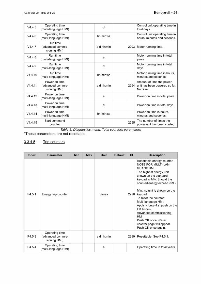
Table 2. Diagnostics menu, Total counters parameters*These parameters are not resettable.
3.3.4.5 Trip counters
V4.4.5Operating time
(multi-language HMI)d
Control unit operating time in total days.
V4.4.6Operating time
(multi-language HMI)hh:min:ss
Control unit operating time in hours, minutes and seconds.
V4.4.7Run time
(advanced commis-sioning HMI)
a d hh:min 2293 Motor running time.
V4.4.8Run time
(multi-language HMI)a
Motor running time in total years.
V4.4.9Run time
(multi-language HMI)d
Motor running time in total days.
V4.4.10Run time
(multi-language HMI)hh:min:ss
Motor running time in hours, minutes and seconds
V4.4.11Power on time
(advanced commis-sioning HMI)
a d hh:min 2294Amount of time the power unit has been powered so far. No reset.
V4.4.12Power on time
(multi-language HMI)a Power on time in total years.
V4.4.13Power on time
(multi-language HMI)d Power on time in total days.
V4.4.14Power on time
(multi-language HMI)hh:min:ss
Power on time in hours, minutes and seconds.
V4.4.15Start command
counter2295
The number of times the power unit has been started.
Index Parameter Min Max Unit Default ID Description
P4.5.1 Energy trip counter Varies 2296
Resettable energy counter.NOTE FOR MULTI-LAN-GUAGE HMI: The highest energy unit shown on the standard keypad is MW. Should the counted energy exceed 999.9
MW, no unit is shown on the keypad.To reset the counter:Multi-language HMI:Apply a long (4 s) push on theOK button.Advanced commissioning HMI:Push OK once. Resetcounter page will appear.Push OK once again.
P4.5.3Operating time
(advanced commis-sioning HMI)
a d hh:min 2299 Resettable. See P4.5.1.
P4.5.4Operating time
(multi-language HMI)a Operating time in total years.

Honeywell • 25 KEYPAD OF THE DRIVE
Table 3. Diagnostics menu, Trip counters parameters
3.3.4.6 Software info
Table 4. Diagnostics menu, Software info parameters
P4.5.5Operating time
(multi-language HMI)d Operating time in total days.
P4.5.6Operating time
(multi-language HMI)hh:min:ss
Operating time in hours, minutes and seconds.
Index Parameter Min Max Unit Default ID Description
V4.6.1Software package
(advanced commis-sioning HMI)
2524
Code for softwareidentification.
V4.6.2Software package ID(multi-language HMI)
V4.6.3Software package
version(multi-language HMI)
V4.6.4 System load 0 100 % 2300 Load on control unit CPU.
V4.6.5Application name
(advanced commis-sioning HMI)
2525 Name of application.
V4.6.6 Application ID 837 Application code.
V4.6.7 Application version 838

KEYPAD OF THE DRIVE Honeywell • 26
3.3.5 I/O and hardware
Various options-related settings are located in this menu.
3.3.5.1 Basic I/O
Monitor here the statuses of inputs and outputs.
Table 5. I/O and Hardware menu, Basic I/O parameters
Index Parameter Min Max Unit Default ID Description
M5.1.1 Digital input 1 0 1 2502 Status of digital input signal
M5.1.2 Digital input 2 0 1 2503 Status of digital input signal
M5.1.3 Digital input 3 0 1 2504 Status of digital input signal
M5.1.4 Digital input 4 0 1 2505 Status of digital input signal
M5.1.5 Digital input 5 0 1 2506 Status of digital input signal
M5.1.6 Digital input 6 0 1 2507 Status of digital input signal
M5.1.7 Analog input 1 mode 1 3 2508
Shows the selected (withjumper) mode for Analogueinput signal1 = 0...20mA3 = 0...10V
M5.1.8 Analog input 1 0 100 % 2509 Status of analog input signal
M5.1.9 Analog input 2 mode 1 3 2510
Shows the selected (withjumper) mode for Analogueinput signal1 = 0...20mA3 = 0...10V
M5.1.10 Analog input 2 0 100 % 2511 Status of analog input signal
M5.1.11 Analog output 1 mode 1 3 2512
Shows the selected (withjumper) mode for Analogueoutput signal1 = 0...20mA3 = 0...10V
M5.1.12 Analog output 1 0 100 % 2513Status of analog output sig-nal
M5.1.13 Relay output 1 0 1 Status of digital output signal
M5.1.14 Relay output 2 0 1 Status of digital output signal
M5.1.15 Relay output 3 0 1 Status of digital output signal
M5.1.16 Thermistor input 0 1Status of thermistor input. See P3.9.21.

Honeywell • 27 KEYPAD OF THE DRIVE
3.3.5.2 Option board slots
The parameters of this group depend on the option board installed. If no option board is placed in slots D or E, no parameters are visible. See chapter 4.5.2 for the location of the slots.
3.3.5.3 Real time clock
Table 6. I/O and Hardware menu, Real time clock parameters
3.3.5.4 Power unit settings, fan control
Table 7. Power unit settings, Fan control
Table 8. Power unit settings, brake chopper
Menu Function Note
Slot D Settings Option board related settings.
Monitoring Monitor option board-related info.
Slot E Settings Option board related settings.
Monitoring Monitor option board-related info.
Index Parameter Min Max Unit Default ID Description
V5.5.1 Battery state 1 3 2 2205
Status of battery. 1 = Not installed2 = Installed3 = Change battery
P5.5.2 Time hh:mm:ss 2201 Current time of day
P5.5.3 Date dd.mm. 2202 Current date
P5.5.4 Year yyyy 2203 Current year
P5.5.5 Daylight saving 1 4 1 2204
Daylight saving rule1 = Off2 = EU3 = US4 = Russia
Index Parameter Min Max Unit Default ID Description
P5.6.1.1 Fan control modeAlways
onOpti-mised
Always on
2377 Fan control mode
M5.6.1.5 Fan lifetime h 0 849 Fan lifetime
P5.6.1.6 Fan lifetime alarm limit 0200,00
0h 50 000 824 Fan lifetime alarm limit
P5.6.1.7 Fan lifetime reset 0 823 Fan lifetime reset
Index Parameter Min Max Unit Default ID Description
P5.6.2.1 Brake chopper modeDis-
abledEnabled Disabled 2526 Brake chopper mode

KEYPAD OF THE DRIVE Honeywell • 28
Table 9. Power unit settings, sine filter
3.3.5.5 Keypad
Table 10. I/O and Hardware menu, Keypad parameters
Index Parameter Min Max Unit Default ID Description
P5.6.4.1 Sine filterDis-
abledEnabled Disabled 2527 Sine filter
Index Parameter Min Max Unit Default ID Description
P5.7.1 Timeout time 0 60 min 0 804
Time after which the display returns to page defined with parameter P5.7.2.0 = Not used
P5.7.2 Default page 0 4 0 2318
0 = None1 = Enter menu index2 = Main menu3 = Control page4 = Multimonitor
P5.7.3 Menu index 0 255 2499Set menu index for desired page and activate with parameter P5.7.2 = 1.
P5.7.4Contrast (advanced commissioning HMI
only)30 70 % 50 830
Set contrast of the display (30...70%).
P5.7.5 Backlight time 0 60 min 5 818
Set the time until the back-light of the display turns off (0...60 min). If set to 0 s, backlight is always on.

Honeywell • 29 KEYPAD OF THE DRIVE
3.3.5.6 Fieldbus
Parameters related to different fieldbus boards can also be found in the I/O and Hardware menu. These parameters are explained in more detail in the respective fieldbus manual.
Submenu level 1 Submenu level 2 Submenu level 3 Submenu level 4
RS-485 Common settings Protocol Modbus/RTUN2BACnet MS/TP
Modbus/RTU Parameters Slave address
Baud rate
Parity type
Stop bits
Communication timeout
Operate mode
Monitoring Fieldbus protocol status
Communication status
Illegal functions
Illegal data addresses
Illegal data values
Slave device busy
Memory parity error
Slave device failure
Last fault response
Control word
Status word
N2 Parameters Device address
Communication timeout
Monitoring Fieldbus protocol status
Communication status
Invalid data
Invalid commands
Command not accepted
Control word
Status word

KEYPAD OF THE DRIVE Honeywell • 30
RS-485 BACnet MS/TP Parameters Baud rate
Autobauding
MAC address
Instance number
Communication timeout
Monitoring Fieldbus protocol status
Communication status
Actual instance number
Fault code
Control word
Status word
Ethernet Common settings IP address mode
Fixed IP IP address
Subnet mask
Default gateway
IP address
Subnet mask
Default gateway
Modbus/TCP Common settings Connection limit
Slave address
Communication timeout
Monitoring* Fieldbus protocol status
Communication status
Illegal functions
Illegal data addresses
Illegal data values
Slave device busy
Memory parity error
Slave device failure
Last fault response
Control word
Status word
BACnet/IP Settings Instance number
Communication timeout
Protocol in use
BBMD IP
BBMD Port
Time to live
Monitoring Fieldbus protocol status
Communication status
Actual instance number
Control word
Status word

Honeywell • 31 KEYPAD OF THE DRIVE
Table 11. Common settings, protocol
Table 12. Modbus RTU parameters (This table is only visible when P5.8.1.1 Protocol = 4/Modbus RTU.)
Table 13. Modbus RTU monitoring (This table is only visible when P5.8.1.1 Protocol = 4/Modbus RTU)
Table 14. N2 parameters (This table is only visible when P5.8.1.1 Protocol = 5/N2)
Index Parameter Min Max Unit Default ID Description
P5.8.1.1 Protocol 0 9 0 2208
0 = No protocol4 = Modbus RTU5 = N29 = BACNet MSTP
Index Parameter Min Max Unit Default ID Description
P5.8.3.1.1 Slave address 1 247 1 2320 Slave address
P5.8.3.1.2 Baud rate 300 230 400 bps 9600 2378 Baud rate
P5.8.3.1.3 Parity type Even None None 2379 Parity type
P5.8.3.1.4 Stop bits 1 2 2 2380 Stop bits
P5.8.3.1.5Communication
timeout0 65 535 s 10 2321 Comm. timeout
P5.8.3.1.6 Operate mode Slave Master Slave 2374 Operate mode
Index Parameter Min Max Unit Default ID Description
M5.8.3.2.1Fieldbus protocol
status0 2381 Fieldbus protocol status
P5.8.3.2.2Communication
status0 0 0 2382 Communication status
M5.8.3.2.3 Illegal functions 0 2383 Illegal functions
M5.8.3.2.4 Illegal data addresses 0 2384 Illegal data addresses
M5.8.3.2.5 Illegal data values 0 2385 Illegal data values
M5.8.3.2.6 Slave device busy 0 2386 Slave device busy
M5.8.3.2.7 Memory parity error 0 2387 Memory parity error
M5.8.3.2.8 Slave device failure 0 2388 Slave device failure
M5.8.3.2.9 Last fault response 0 2389 Last fault response
M5.8.3.2.10 Control word 16#0 2390 Control word
M5.8.3.2.11 Status word 16#0 2391 Status word
Index Parameter Min Max Unit Default ID Description
P 5.8.3.1.1 Device address 1 255 1 2350 Device address
P 5.8.3.1.2Communication
timeout0 255 10 2351
Communication timeout
Index Parameter Min Max Unit Default ID Description
M5.8.3.2.1Fieldbus protocol
status0 2399 Fieldbus protocol status
M5.8.3.2.2Communication
status0 2400 Communication status

KEYPAD OF THE DRIVE Honeywell • 32
Table 15. N2 monitoring (This table is only visible when P5.8.1.1 Protocol = 5/N2)
Table 16. BACnet MSTP parameters (This table is only visible when P5.8.1.1 Protocol = 9/BACNetMSTP)
Table 17. BACnet MSTP monitoring (This table is only visible when P5.8.1.1 Protocol = 9/BACNetMSTP)
Table 18. Ethernet common settings
Table 19. Fixed IP
M5.8.3.2.3 Invalid data 0 2401 Invalid data
M5.8.3.2.4 Invalid commands 0 2402 Invalid commands
M5.8.3.2.5 Command NACK 0 2403 Command NACK
M5.8.3.2.6 Control word 16#0 2404 Control word
M5.8.3.2.7 Status word 16#0 2405 Status word
Index Parameter Min Max Unit Default ID Description
P5.8.3.1.1 Baud rate 9600 76 800 bps 9600 2392 Baud rate
P5.8.3.1.2 Autobauding 0 1 0 2330 Autobauding
P5.8.3.1.3 MAC address 1 127 1 2331 MAC address
P5.8.3.1.4 Instance number 04 194 303
0 2332 Instance number
P5.8.3.1.5Communication
timeout0 65 535 10 2333
Communication timeout
Index Parameter Min Max Unit Default ID Description
M5.8.3.2.1Fieldbus protocol
status0 2393
Fieldbus protocol status
M5.8.3.2.2Communication
status0 2394
Communication status
M5.8.3.2.3 Actual instance 0 2395 Actual instance
M5.8.3.2.4 Fault code 0 2396 Fault code
M5.8.3.2.5 Control word 16#0 2397 Control word
M5.8.3.2.6 Status word 16#0 2398 Status word
Index Parameter Min Max Unit Default ID Description
P5.9.1.1 IP address mode 0 1 1 24820 = Fixed IP1 = DHCP with AutoIP
Index Parameter Min Max Unit Default ID Description
P5.9.1.2.1 IP address 192.168.0.10 2529This parameter is in use if P5.9.1.1 = 0/Fixed IP
P5.9.1.2.2 Subnet mask 255.255.0.0 2530This parameter is in use if P5.9.1.1 = 0/Fixed IP
P5.9.1.2.3 Default gateway 192.168.0.1 2531This parameter is in use if P5.9.1.1 = 0/Fixed IP
M5.9.1.3 IP address 0 2483 IP address
M5.9.1.4 Subnet mask 0 2484 Subnet mask
M5.9.1.5 Default gateway 0 2485 Default gateway
M5.9.1.6 MAC address 2486 MAC address

Honeywell • 33 KEYPAD OF THE DRIVE
Table 20. Modbus TCP common settings
Table 21. BACnet IP settings
Table 22. BACnet IP monitoring
Index Parameter Min Max Unit Default ID Description
P5.9.2.1.1 Connection limit 0 3 3 2446 Connection limit
P5.9.2.1.2 Slave address 0 255 255 2447 Slave address
P5.9.2.1.3Communication
timeout0 65 535 s 10 2448
Communication timeout
Index Parameter Min Max Unit Default ID Description
P5.9.3.1.1 Instance number 04 194 303
0 2406 Instance number
P5.9.3.1.2Communication
timeout0 65 535 0 2407
Communication timeout
P5.9.3.1.3 Protocol in use 0 1 0 2408 Protocol in use
P5.9.3.1.4 BBMD IP 192.168.0.1 2409 BBMD IP
P5.9.3.1.5 BBMD Port 1 65 535 47 808 2410 BBMD Port
P5.9.3.1.6 Time to live 0 255 0 2411 Time to live
Index Parameter Min Max Unit Default ID Description
M5.9.3.2.1Fieldbus protocol
status0 2412 Fieldbus protocol status
P5.9.3.2.2Communication
status0 0 0 2413 Communication status
M5.9.3.2.3 Actual instance 0 2414 Actual instance
M5.9.3.2.4 Control word 16#0 2415 Control word
M5.9.3.2.5 Status word 16#0 2416 Status word

KEYPAD OF THE DRIVE Honeywell • 34
3.3.6 User settings
Table 23. User settings menu, General settings
3.3.6.1 Parameter backup
* = Only available with Advanced Commissioning HMI
Table 24. User settings menu, Parameter backup
Table 25. User settings menu, Parameter compare
Index Parameter Min Max Unit Default ID Description
P6.1 Language selections Varies Varies Varies 802Depends on language pack-age.
M6.5 Parameter backup See Table 24 below.
M6.6 Parameter compare See Table 25 below.
P6.7 Drive name Give name of drive if needed.
Index Parameter Min Max Unit Default ID Description
P6.5.1Restore factory
defaults831
Restores factory default set-tings.NOTE: Restarts the drive if motor is not running.
P6.5.2 Save to keypad * 2487Save parameter values tokeypad to e.g. copy them toanother drive.
P6.5.3 Restore from keypad * 2488Load parameter values fromkeypad to the drive.
P6.5.4 Save to Set 1 2489Save parameter values to parameter set 1.
P6.5.5 Restore from Set 1 2490Load parameter values from parameter set 1.
P6.5.6 Save to Set 2 2491Save parameter values to parameter set 2.
P6.5.7 Restore from Set 2 2492Load parameter values from parameter set 2.
Index Parameter Min Max Unit Default ID Description
P6.6.1 Active set - Set 1 0 2493Starts comparing parame-ters to the selected set
P6.6.2 Active set - Set 2 0 2494Starts comparing parame-ters to the selected set
P6.6.3 Active set - Defaults 0 2495Starts comparing parame-ters to the selected set
P6.6.4 Active set - Keypad set 0 2496Starts comparing parame-ters to the selected set
P6.7 Drive name Drive 2528 The name of the drive

Honeywell • 35 KEYPAD OF THE DRIVE
3.3.7 Favourites
NOTE: This menu is available in Advanced Commissioning HMI only.
Favourites are typically used to collect a set of parameters or monitoring signals from any of the keypad menus. You can add items or parameters to the Favourites folder, see chapter
To remove an item or a parameter from the Favourites folder, do the following:
Motor Nom Freq
50.00 Hz
Favorites
STOP READY I/O
Help
Motor Nom Freq
STOP READY I/O
Monitor
Rem from favorites
9172
.em
f
OK OK

COMMISSIONING Honeywell • 36
4. COMMISSIONING
The parameters of this application are listed in chapter 4.5 of this manual and explained in more detail in chapter 4.6.
4.1 Specific functions of SmartVFD HVAC/SmartDrive HVAC
The SmartVFD HVAC/SmartDrive HVAC is an easy-to-use application for basic Pump and Fan applications where only one motor and one drive is needed and also offers extensive possibil-ities for PID control.
Features
• Startup Wizard for extremely fast setup for basic pump or fan applications• Mini-Wizards to ease the setup of standalone PID, Cascade and Fire Mode control
applications• Loc/Rem-button for easy change between Local (keypad) and Remote control place.
The remote control place is selectable by parameter (I/O or Fieldbus)• Control page for easy operation and monitoring of the most essential values.• Run interlock input (Damper interlock). Drive will not start before this input is activated.• Different pre-heat modes used to avoid condensation problems• Real-time clock and timer functions available (optional battery required). Possible to
program 3 time channels to achieve different functions on the drive (e.g. Start/Stop and Preset frequencies)
• External PID-controller available. Can be used to control e.g. a valve using the drive's I/O
• Sleep mode function which automatically enables and disables drive running with user defined levels to save energy.
• 2-zone PID-controller (2 different feedback signals; minimum and maximum control)• Two setpoint sources for the PID-control. Selectable with digital input• PID setpoint boost function• Feedforward function to improve the response to the process changes• Process value supervision• Pump and Fan Cascade control for controlling a system with multiple pumps or fans• Power ride-through for automatically adapting the operation to avoid faults in
e.g.short-time voltage loss• Overtemperature ride-through for automatically adapting the operation to avoid faults
in abnormal ambient temperatures• Pressure loss compensation for compensating pressure losses in the pipework e.g.
when sensor is incorrectly placed near the pump or fan• Single input control where the analogue signal (0-10V or 4-20mA) can also be used
to start and stop the motor without additional inputs• Resonance sweep wizard to very easily set up skip frequency areas to avoid reso-
nances in the system • RTO - Ramp Time Optimizer to automatically adapt to the system to avoid fast accel-
erations and decelerations which might harm the water pipes or air ducts • Pump soft fill function to prevent overpressures when filling the pipework with liquid• Sine filter feature is available

Honeywell • 37 COMMISSIONING
4.2 Example of control connections
Table 26. Connection example, standard I/O board
Terminal Signal Default
1 +10 Vref Reference output
2 AI1+Analogue input, voltage or current*
Voltage3 AI1- Analogue input common
(current)
4 AI2+ Analogue input, voltage or current
Current5 AI2- Analogue input common
(current)
6 24Vout 24V aux. voltage
7 GND I/O ground
8 DI1 Digital input 1 Start FWD
9 DI2 Digital input 2 Start REV
10 DI3 Digital input 3 Fault
11 CM Common A for DIN1-DIN6**
12 24Vout 24V aux. voltage
13 GND I/O ground
14 DI4 Digital input 4Preset freq select 1
15 DI5 Digital input 5Preset freq select 2
16 DI6 Digital input 6 Fault reset
17 CM Common A for DIN1-DIN6**
18 AO1+ Analogue signal (+output) Output frequency19 AO-/GND Analogue output common
30 +24 Vin 24V auxiliary input voltage
A RS485 Serial bus, negative
B RS485 Serial bus, positive
Reference potentiometer 1...10 kΩ
Remote reference4...20mA/0...10V(programmable)
mA
To Relay board 1 or 2
*Selectable with DIP switches, see Installation Manual**Digital inputs can be isolated from ground. See Instal-lation Manual.
9343A uk
I/O ground
I/O ground

COMMISSIONING Honeywell • 38
Table 27. Connection example, Relay board
Table 28. Connection example, Relay board 2
9344.emf
Relay board 1Default
Terminal Signal
21 RO1/1 NCRelay output 122 RO1/2 CM
23 RO1/3 NO24 RO2/1 NC25 RO2/2 CM26 RO2/3 NO32 RO3/1 CM
33 RO3/2 NO
FromStandard I/O board
From term.#13
From term.#6 or 12
RUN RUN
Relay output 2 FAULT
Relay output 3 READY
Relay board 2Default
Terminal Signal
21 RO1/1 NCRelay output 122 RO1/2 CM
23 RO1/3 NO24 RO2/1 NC25 RO2/2 CM26 RO2/3 NO28 TI1+29 TI1-
From Standard I/O board
From term. #13
From term. #12
RUN RUN
Relay output 2 FAULT
NOACTIONThermistor input
9439_uk
Honeywell • 39 COMMISSIONING
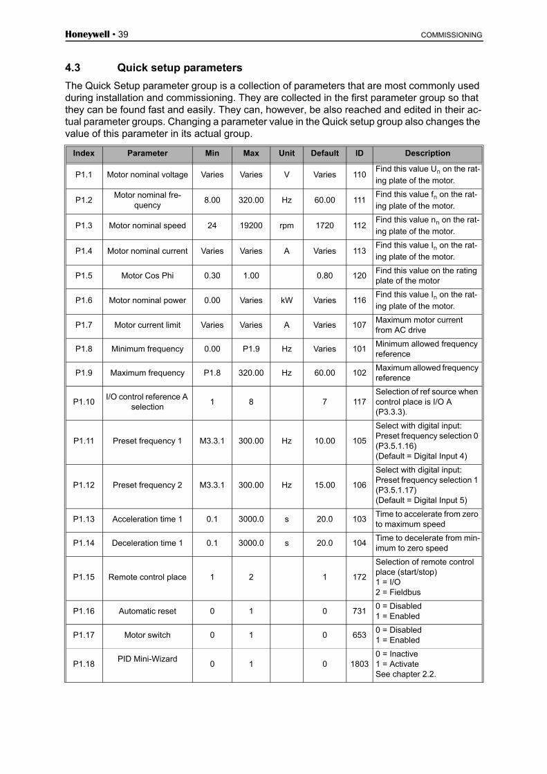
4.3 Quick setup parameters
The Quick Setup parameter group is a collection of parameters that are most commonly used during installation and commissioning. They are collected in the first parameter group so that they can be found fast and easily. They can, however, be also reached and edited in their ac-tual parameter groups. Changing a parameter value in the Quick setup group also changes the value of this parameter in its actual group.
Index Parameter Min Max Unit Default ID Description
P1.1 Motor nominal voltage Varies Varies V Varies 110Find this value Un on the rat-
ing plate of the motor.
P1.2Motor nominal fre-
quency8.00 320.00 Hz 60.00 111
Find this value fn on the rat-
ing plate of the motor.
P1.3 Motor nominal speed 24 19200 rpm 1720 112Find this value nn on the rat-
ing plate of the motor.
P1.4 Motor nominal current Varies Varies A Varies 113Find this value In on the rat-
ing plate of the motor.
P1.5 Motor Cos Phi 0.30 1.00 0.80 120Find this value on the rating plate of the motor
P1.6 Motor nominal power 0.00 Varies kW Varies 116Find this value In on the rat-
ing plate of the motor.
P1.7 Motor current limit Varies Varies A Varies 107Maximum motor current from AC drive
P1.8 Minimum frequency 0.00 P1.9 Hz Varies 101Minimum allowed frequency reference
P1.9 Maximum frequency P1.8 320.00 Hz 60.00 102Maximum allowed frequency reference
P1.10I/O control reference A
selection1 8 7 117
Selection of ref source when control place is I/O A (P3.3.3).
P1.11 Preset frequency 1 M3.3.1 300.00 Hz 10.00 105
Select with digital input:Preset frequency selection 0 (P3.5.1.16)(Default = Digital Input 4)
P1.12 Preset frequency 2 M3.3.1 300.00 Hz 15.00 106
Select with digital input: Preset frequency selection 1 (P3.5.1.17)(Default = Digital Input 5)
P1.13 Acceleration time 1 0.1 3000.0 s 20.0 103Time to accelerate from zero to maximum speed
P1.14 Deceleration time 1 0.1 3000.0 s 20.0 104Time to decelerate from min-imum to zero speed
P1.15 Remote control place 1 2 1 172
Selection of remote control place (start/stop)1 = I/O2 = Fieldbus
P1.16 Automatic reset 0 1 0 7310 = Disabled1 = Enabled
P1.17 Motor switch 0 1 0 6530 = Disabled1 = Enabled
P1.18PID Mini-Wizard
0 1 0 18030 = Inactive1 = ActivateSee chapter 2.2.

COMMISSIONING Honeywell • 40
Table 29. Quick setup parameter group
P1.19 PFC Wizard * 0 1 00 = Inactive1 = ActivateSee chapter 2.3.
P1.20 Firemode Wizard 0 1 00 = Inactive1 = Active

Honeywell • 41 COMMISSIONING
4.4 Monitor group
The drive provides you with a possibility to monitor the actual values of parameters and signals as well as statuses and measurements. Some of the values to be monitored are customizable.
4.4.1 Multimonitor view with advanced commissioning HMI
On the multi-monitor page, you can collect nine values that you wish to monitor. See page 22 for more information.
4.4.2 Basic
See Table 30 in which the basic monitoring values are presented.
NOTE!
Only Basic I/O board statuses are available in the Monitor menu. Statuses for all I/O board signals can be found as raw data in the I/O and Hardware system menu.
Check expander I/O board statuses when required in the I/O and Hardware system menu.
Index Monitoring value Unit ID Description
V2.2.1 Output frequency Hz 1 Output frequency to motor
V2.2.2 Frequency reference Hz 25 Frequency reference to motor control
V2.2.3 Motor speed rpm 2 Motor speed in rpm
V2.2.4 Motor current A 3
V2.2.5 Motor torque % 4 Calculated shaft torque
V2.2.7 Motor shaft power % 5 Total power consumption of AC drive
V2.2.8 Motor shaft power kW/hp 73
V2.2.9 Motor voltage V 6
V2.2.10 DC link voltage V 7
V2.2.11 Unit temperature °C/°F 8 Heatsink temperature
V2.2.12 Motor temperature % 9 Calculated motor temperature
V2.2.13 Analog input 1 % 59 Signal in percent of used range
V2.2.14 Analog input 2 % 60 Signal in percent of used range
V2.2.15 Analog output 1 % 81 Signal in percent of used range
V2.2.16 Motor preheat 1228 0 = OFF1 = Heating (feeding DC-current)
V2.2.17 Drive Status Word 43 Bit coded status of driveB1=ReadyB2=RunB3=FaultB6=RunEnableB7=AlarmActiveB10=DC Current in stopB11=DC Brake ActiveB12=RunRequestB13=MotorRegulatorActive
V2.2.18 Last active fault 37 The fault code of latest activated fault that has not been reset.

COMMISSIONING Honeywell • 42
Table 30. Monitoring menu items
V2.2.19 Fire mode status 1597 0=Disabled1=Enabled2=Activated (Enabled + DI open)3=Test mode
V2.2.20 Appl.StatusWord1 89 B0 = Interlock 1B1 = Interlock 2B5 = I/O A Control Act.B6 = I/O B Control Act.B7 = Fieldbus Control Act.B8 = Local Control Act.B9 = PC Control Act.B10 = Preset Frequencies Act.B12 = FireMode Act.B13 = PreHeat Act.
V2.2.21 Appl.StatusWord2 90 B0 = Acc/Dec ProhibitedB1 = Motor Switch Act.
Index Monitoring value Unit ID Description

Honeywell • 43 COMMISSIONING
4.4.3 Timer functions monitoring
Here you can monitor values of timer functions and the Real Time Clock.
Table 31. Monitoring of timer functions
4.4.4 PID1 controller monitoring
Table 32. PID1-controller value monitoring
4.4.5 PID2 controller monitoring
Table 33. PID2-controller value monitoring
Index Monitoring value Unit ID Description
V2.3.1 TC 1, TC 2, TC 3 1441 Possible to monitor the statuses of the three Time Channels (TC)
V2.3.2 Interval 1 1442 Status of timer interval
V2.3.3 Interval 2 1443 Status of timer interval
V2.3.4 Interval 3 1444 Status of timer interval
V2.3.5 Interval 4 1445 Status of timer interval
V2.3.6 Interval 5 1446 Status of timer interval
V2.3.7 Timer 1 s 1447 Remaining time on timer if active
V2.3.8 Timer 2 s 1448 Remaining time on timer if active
V2.3.9 Timer 3 s 1449 Remaining time on timer if active
V2.3.10 Real time clock 1450
Index Monitoring value Unit ID Description
V2.4.1 PID1 setpoint Varies 20 Process units selected with parameter
V2.4.2 PID1 feedback Varies 21 Process units selected with parameter
V2.4.3 PID1 error value Varies 22 Process units selected with parameter
V2.4.4 PID1 output % 23 Output to motor control or external control (AO)
V2.4.5 PID1 status 24 0=Stopped1=Running3=Sleep mode4=In dead band (see page 78)
Index Monitoring value Unit ID Description
V2.5.1 PID2 setpoint Varies 83 Process units selected with parameter
V2.5.2 PID2 feedback Varies 84 Process units selected with parameter
V2.5.3 PID2 error value Varies 85 Process units selected with parameter
V2.5.4 PID2 output % 86 Output to external control (AO)
V2.5.5 PID2 status 87 0=Stopped1=Running2=In dead band (see page 78)

COMMISSIONING Honeywell • 44
4.4.6 Multi-pump
Table 34. Pump and fan cascade monitoring
4.4.7 Maintenance timers
Table 35. Maintenance timers monitoring
4.4.8 Fieldbus data monitoring
Index Monitoring value Unit ID Description
V2.6.1 Motors running 30 The number of motors running when PFC function is used.
V2.6.2 Autochange 1114 Informs the user if autochange is requested.
Index Monitoring value Unit ID Description
V2.7.1 Counter 1 h/revs 1101 Status of counter (Revs*1000 or hours)
V2.7.2 Counter 2 h/revs 1102 Status of counter (Revs*1000 or hours)
V2.7.3 Counter 3 h/revs 1103 Status of counter (Revs*1000 or hours)
Index Monitoring value Unit ID Description
V2.8.1 FB Control Word 874 Fieldbus control word used by application in bypass mode/format. Depending on the fieldbus type or profile the data can be modified before sent to application.
V2.8.2 FB speed reference 875 Speed reference scaled between minimum and maxi-mum frequency at the moment it was received by the application. Minimum and maximum frequencies can changed after the reference was received without affect-ing the reference.
V2.8.3 FB data in 1 876 Raw value of process data in 32-bit signed format
V2.8.4 FB data in 2 877 Raw value of process data in 32-bit signed format
V2.8.5 FB data in 3 878 Raw value of process data in 32-bit signed format
V2.8.6 FB data in 4 879 Raw value of process data in 32-bit signed format
V2.8.7 FB data in 5 880 Raw value of process data in 32-bit signed format
V2.8.8 FB data in 6 881 Raw value of process data in 32-bit signed format
V2.8.9 FB data in 7 882 Raw value of process data in 32-bit signed format
V2.8.10 FB data in 8 883 Raw value of process data in 32-bit signed format
V2.8.11 FB Status Word 864 Fieldbus status word sent by application in bypass mode/format. Depending on the FB type or profile the data can be modified before sent to the FB.
V2.8.12 FB speed actual 865 Actual speed in %. 0 and 100% correspond to minimum and maximum frequencies respectively. This is continu-ously updated depending on the momentary min and max frequencies and the output frequency.
V2.8.13 FB data out 1 866 Raw value of process data in 32-bit signed format
V2.8.14 FB data out 2 867 Raw value of process data in 32-bit signed format
V2.8.15 FB data out 3 868 Raw value of process data in 32-bit signed format
V2.8.16 FB data out 4 869 Raw value of process data in 32-bit signed format

Honeywell • 45 COMMISSIONING
Table 36. Fieldbus data monitoring
4.4.9 Temperature inputs
V2.8.17 FB data out 5 870 Raw value of process data in 32-bit signed format
V2.8.18 FB data out 6 871 Raw value of process data in 32-bit signed format
V2.8.19 FB data out 7 872 Raw value of process data in 32-bit signed format
V2.8.20 FB data out 8 873 Raw value of process data in 32-bit signed format
Index Monitoring value Min Max Unit ID Description
V2.9.1 Temperature Input 1 -50.00 200.00 °C/°F 50 Measured value of Tempera-ture Input 1. The list of temper-ature inputs are filled by taking the 3 first available tempera-ture inputs starting from slot D and going to slot E. If input is available but no sensor is con-nected, the maximum value is shown because measured resistance is endless.
V2.9.2 Temperature Input 2 -50.00 200.00 °C/°F 51 Measured value of Tempera-ture Input 2. The list of temper-ature inputs are filled by taking the 3 first available tempera-ture inputs starting from slot D and going to slot E. If input is available but no sensor is con-nected, the maximum value is shown because measured resistance is endless.
V2.9.3 Temperature Input 3 -50.00 200.00 °C/°F 52 Measured value of Tempera-ture Input 3. The list of temper-ature inputs are filled by taking the 3 first available tempera-ture inputs starting from slot D and going to slot E. If input is available but no sensor is con-nected, the maximum value is shown because measured resistance is endless.
Index Monitoring value Unit ID Description

COMMISSIONING Honeywell • 46
4.5 Application parameters
Find the parameter menu and the parameter groups as guided below.
The HVAC Application embodies the following parameter groups:
Table 37. Parameter groups
Menu and Parameter group Description
Group 3.1: Motor settings Basic and advanced motor settings
Group 3.2: Start/Stop setup Start and stop functions
Group 3.3: Control reference settings Frequency reference setup
Group 3.4: Ramp & Brakes Setup Acceleration/Deceleration setup
Group 3.5: I/O Configuration I/O programming
Group 3.6: Fieldbus Data Mapping Process data in/out mapping
Group 3.7: Prohibit Frequencies Prohibit frequencies programming
Group 3.8: Limit supervisions Programmable limit controllers
Group 3.9: Protections Protections configuration
Group 3.10: Automatic reset Auto reset after fault configuration
Group 3.11: Application SettingsMotor power and temperature units configura-tion
Group 3.12: Timer functionsConfiguration of 3 timers based on Real Time Clock.
Group 3.13: PID-controller 1Parameters for PID Controller 1. Motor control or external usage.
Group 3.14: PID-controller 2Parameters for PID Controller 2. External usage.
Group 3.15: Pump and Fan Cascade Parameters for Pump and Fan Cascade.
Group 3.16: Maintenance counters Parameters for Maintenance counters.
Group 3.17: Fire mode Parameters for Fire Mode.
STOP READY Keypad
Motor Settings( 2 )
Start/Stop Setup
( 7 )
References( 18 )
Parameters
ID: M3.1
STOP READY Keypad
Main Menu
Quick Setup( 17 )
( 6 )MonitorParameters
( 13 )
ID: M3.1
9151
.em
f
OK

Honeywell • 47 COMMISSIONING
4.5.1 Column explanations
Index = Location indication on the keypad; Shows the operator the parameter number.
Parameter = Name of parameterMin = Minimum value of parameterMax = Maximum value of parameterUnit = Unit of parameter value; Given if availableDefault = Value preset by factoryID = ID number of the parameterDescription = Short description of parameter values or its function
= More detailed information on this parameter is available in chapter 4.6. HVAC Application; In the digital document a click on the parameter name leads you sometimes to the detailed description

COMMISSIONING Honeywell • 48
4.5.2 Parameter programming
The programming of digital inputs is very flexible. There are no digital terminals assigned only for certain function. You can choose the terminal of your choice for the certain function, in other words, functions appear as parameters which the operator defines a certain input for. For a list of functions for the digital inputs, see Table 44 on page 61.
Also Time Channels can be assigned to digital inputs. See more information on page 76.
The selectable values of the programmable parameters are of type
DigIN SlotA.1 (advanced commissioning HMI) or
dI A.1 (multi-language HMI)
in which
‘DigIN / dI’ stand for digital input.‘Slot_’ refers to the board; A and B are basic boards, D and E are option boards (see Figure 16). See chapter 4.5.2.3.The number after the board letter refers to the respective terminal on the selected board. Hence, SlotA.1 means terminal DIN1 on the basic board in board slot A. The parameter (signal) is not connected to any terminal, i.e. it is not used, if, instead of a letter, the final number is preceded by a ‘0’ (for example DigIN Slot0.1 / dI 0.1).
Figure 16. Option board slots
Optionboardslot E
Optionboardslot D

Honeywell • 49 COMMISSIONING
EXAMPLE:
You want to connect the Control signal 2 A (parameter P3.5.1.2) to digital input DI2 on Basic I/O board.
4.5.2.1 Example programming with advanced commissioning HMI
Note: For slot 0.x, the function of the value of x is:
1 = always false
2-9=always true
1 Locate the parameter Control signal 2 A (P3.5.1.2) on the keypad.
2 Enter the Edit mode.
3
Change the value: The editable part of the value (DigIN Slot0) is underlined and blinking. Change the slot to DigIN SlotA (or assign the signal to Time Channel) with the arrow keys up and down. Make the terminal value (.1) editable by press-ing the right key once and change the value to ‘2’ with arrow keys up and down.
Accept the change with OK button or return to previous menu level with BACK/RESET button.
STOP READY Keypad
Main Menu
Quick Setup( 17 )
( 5 )Monitor
ID: M3
Parameters
( 12 )
STOP READY Keypad
References( 18 )
Parameters
I/O Config
( 4 )
Ramps and Brakes( 7 )
ID: M3.5
STOP READY Keypad
I/O Config
Digital Inputs
( 26 )
Analog Inputs( 36 )
Analog Inputs
Digital Outputs
( 1 )
ID: M3.5.1
STOP READY Keypad
Digital Inputs
Ctrl Signal 1 A
Ctrl Signal 2 ADigIn Slot0.1
DigIn Slot0.1
DigIn SlotA.1
Ctrl Signal 1 B
ID:404 M3.5.1.2
9149
.em
f
OK OK OK
STOP READY Keypad
Digital Inputs
Ctrl Signal 1 A
Ctrl Signal 2 ADigIn Slot0.1
DigIn Slot0.1
DigIn SlotA.1
Ctrl Signal 1 B
ID:404 M3.5.1.2
STOP READY Keypad
Ctrl signal 2 A
Edit
Help
Add to favorites
ID: M3.5.1.2
STOP READY Keypad
Ctrl signal 2 A
Min:
Max:
ID:404 M3.5.1.2
DigIN SlotA.2DigIN Slot0DigIN SlotADigIN SlotBDigIN SlotCDigIN SlotDDigIN SlotETimeChannelFieldbus CWLLP signal
0-10VariesVariesVariesVariesVaries1-30-311-5
9150
.em
f
OK OK

COMMISSIONING Honeywell • 50
4.5.2.2 Example programming with multi-language HMI
1 Locate the parameter Control signal 2 A (P3.5.1.2) on the keypad Parameters > I/O Config > Digital Inputs.
2Enter the Edit mode by pressing OK. The initial character starts to blink. Change the value of signal source to ‘A’ with the arrow buttons.Then press the arrow button right. Now the terminal number blinks. Connect the parameter Control signal 2 A (P3.5.1.2) to terminal DI2 by setting the terminal number to ‘2’.
9156
.em
fOK OK
OK
9157
.em
fOK OK

Honeywell • 51 COMMISSIONING
4.5.2.3 Descriptions of signal sources:
Table 38. Descriptions of signal sources
Source Function
Slot0 0= Always FALSE, 1-9 = Always TRUE
SlotA Number corresponds to digital input in the slot.
SlotB Number corresponds to digital input in the slot.
SlotC Number corresponds to digital input in the slot.
SlotD Number corresponds to digital input in the slot.
SlotE Number corresponds to digital input in the slot.
TimeChannel (tCh)
1=Time Channel1, 2=Time Channel2, 3=Time Channel3

COMMISSIONING Honeywell • 52
4.5.3 Group 3.1: Motor settings
4.5.3.1 Basic Settings
Table 39. Basic motor settings
Index Parameter Min Max Unit Default ID Description
P3.1.1.1 Motor nominal voltage Varies Varies V Varies 110
Find this value Un on the
rating plate of the motor. This parameter sets the volt-age at the field weakening point to 100% * UnMotor.
Note also used connection (Delta/Star).
P3.1.1.2Motor nominal fre-
quency8.00 320.00 Hz 60.00 111
Find this value fn on the rat-
ing plate of the motor.
P3.1.1.3 Motor nominal speed 24 19200 rpm 1720 112Find this value nn on the rat-
ing plate of the motor.
P3.1.1.4 Motor nominal current Varies Varies A Varies 113Find this value In on the rat-
ing plate of the motor.
P3.1.1.5 Motor Cos Phi 0.30 1.00 0.80 120Find this value on the rating plate of the motor
P3.1.1.6 Motor nominal power Varies Varies kW Varies 116Find this value In on the rat-ing plate of the motor.
P3.1.1.7 Motor current limit Varies Varies A Varies 107Maximum motor current from drive
P3.1.1.8 Motor type 0 1 0 6500=IM1=PMM

Honeywell • 53 COMMISSIONING
4.5.3.2 Motor Control Settings
Index Parameter Min Max Unit Default ID Description
P3.1.2.1 Switching frequency 1.5 Varies kHz Varies 601
Motor noise can be mini-mised using a high switch-ing frequency. Increasing the switching frequency reduces the capacity of the drive. It is recommended to use a lower frequency when the motor cable is long in order to minimize capaci-tive currents in the cable.
P3.1.2.2 Motor switch 0 1 0 653
Enabling this function pre-vents the drive from tripping when the motor switch is closed and opened e.g. using flying start.0 = Disabled1 = Enabled
P3.1.2.3 Zero frequency voltage 0.00 40.00 % Varies 606
This parameter defines the zero frequency voltage of the U/f curve. The default value varies according to unit size.
P3.1.2.4 Motor preheat function 0 3 0 1225
0 = Not used1 = Always in stop state2 = Controlled by DI3 = Temperature limit (heat-sink)NOTE: Virtual digital input can be activated by Real Time Clock
P3.1.2.5Motor preheat temper-
ature limit-20 80 °C/°F 0 1226
Motor preheat is switched on when the heatsink tem-perature goes below this level (if par. P3.1.2.4 is set to Temperature limit.If limit is e.g. 10°C feeding current starts at 10 °C and stops at 11°C (1-degree hysteresis).
P3.1.2.6 Motor preheat current 0 0.5*IL A Varies 1227
DC current for pre-heating of motor and drive in stop state. Activated by digital input or by temperature limit.
P3.1.2.7 U/F ratio selection 0 1 0 108
Type of U/f curve between zero frequency and the field weakening point.0 = Linear1 = Squared
P3.1.2.8 Overvoltage controller 0 1 1 6070 = Disabled1 = Enabled
P3.1.2.9Undervoltage control-
ler0 1 1 608
0 = Disabled1 = Enabled
P3.1.2.10 Energy optimization 0 1 0 6660 = Disabled1 = Enabled

COMMISSIONING Honeywell • 54
Table 40. Advanced motor settings
P3.1.2.11 Flying start options 0 1 0 15900 = Both directions1 = FreqRef direction

Honeywell • 55 COMMISSIONING
4.5.4 Group 3.2: Start/Stop setup
Start/Stop commands are given differently depending on the control place.
Remote control place (I/O A): Start, stop and reverse commands are controlled by 2 digital inputs chosen with parameters P3.5.1.1 and P3.5.1.2. The functionality/logic for these inputs is then selected with parameter P3.2.6 (in this group).
Remote control place (I/O B): Start, stop and reverse commands are controlled by 2 digital inputs chosen with parameters P3.5.1.3 and P3.5.1.4. The functionality/logic for these inputs is then selected with parameter P3.2.7 (in this group).Local control place (Keypad): Start and stop commands come from the keypad buttons, while the direction of rotation is selected by the parameter P3.3.7.Remote control place (Fieldbus): Start, stop and reverse commands come from fieldbus.
Index Parameter Min Max Unit Default ID Description
P3.2.1Remote control
place0 1 0 172
Selection of remote control place (start/stop). Can be used to change back to remote control from PC e.g. in case of a broken panel.0=I/O control1=Fieldbus control
P3.2.2 Local/Remote 0 1 0 211
Switch between local and remote control places0=Remote 1=Local
P3.2.3Keypad Master
Stop0 1 1 1806
0=Disable1=Enable
P3.2.4 Start function 0 1 0 5050=Ramping1=Flying start
P3.2.5 Stop function 0 1 0 5060=Coasting1=Ramping
P3.2.6I/O A start/stop
logic0 3 0 300
Logic = 0Ctrl sign 1 = Start fwdCtrl sign 2 = Start bwdLogic = 1Ctrl sign 1 = Start fwd pulse (3-wire)Ctrl sign 2 = Stop pulse(3-wire)Logic = 2Ctrl sign 1 = Start fwd pulseCtrl sign 2 = Start bwd pulseLogic = 3Ctrl sign 1 = StartCtrl sign 2 = ReverseLogic = 4Ctrl sign 1 = Start pulseCtrl sign 2 = Reverse pulseLogic = 5Ctrl sign 1 = AI1 thresholdCtrl sign 2 = AI1 threshold
P3.2.7I/O B start/stop
logic0 3 0 363 See above.

COMMISSIONING Honeywell • 56
Table 41. Start/Stop Setup menu
P3.2.8 AI1 start threshold 3.00 100.00 % 20.00 185
If P3.2.6 (I/O Start/Stop Logic) is set to value 3 (AI1 threshold) the motor will start at the level set with parame-ter this parameter and stop at the same -2% AI1 can also be used as frequency reference at the same time.
P3.2.9 Fieldbus start logic 0 1 1 8890=Rising edge required1=State

Honeywell • 57 COMMISSIONING
4.5.5 Group 3.3: Control reference settings
The requency reference source is programmable for all control places except PC, which always takes the reference from the PC tool.Remote control place (I/O A): The source of frequency reference can be selected with parameter P3.3.3.Remote control place (I/O B): The source of frequency reference can be selected with parameter P3.3.4.Local control place (Keypad): If the default selection for parameter P3.3.5 is used the reference set with parameter P3.3.6 applies.Remote control place (Fieldbus): The frequency reference comes from fieldbus if the default value for parameter P3.3.9 is kept.
Index Parameter Min Max Unit Default ID Description
P3.3.1 Minimum frequency 0.00 P3.3.2 Hz 20.00 101Minimum allowed frequency reference
P3.3.2 Maximum frequency P3.3.1 320.00 Hz 50 / 60 102Maximum allowed frequency reference
P3.3.3I/O control reference A
selection1 8 6 117
Selection of ref source when control place is I/O A1 = Preset Frequency 02 = Keypad reference3 = Fieldbus4 = AI15 = AI26 = AI1+AI27 = PID 1 reference8 = Motor potentiometer
P3.3.4I/O control reference B
selection1 8 4 131
Selection of ref source when control place is I/O B. See above.NOTE: I/O B control place can only be forced active with digital input (P3.5.1.5).
P3.3.5Keypad Ctrl Refer-
ence selection1 8 2 121
Selection of ref source when control place is keypad:1 = Preset Frequency 02 = Keypad3 = Fieldbus4 = AI15 = AI26 = AI1+AI27 = PID 1 reference8 = Motor potentiometer
P3.3.6 Keypad reference 0.00 P3.3.2 Hz 0.00 184The frequency reference can be adjusted on the keypad with this parameter.
P3.3.7 Keypad direction 0 1 0 1230 = Forward1 = Reverse
P3.3.8Keypad reference
copy0 2 1 181
Selects function for Run state & Reference copy when changing to Keypad control:0 = Copy reference1 = Copy ref & Run State2 = No copying
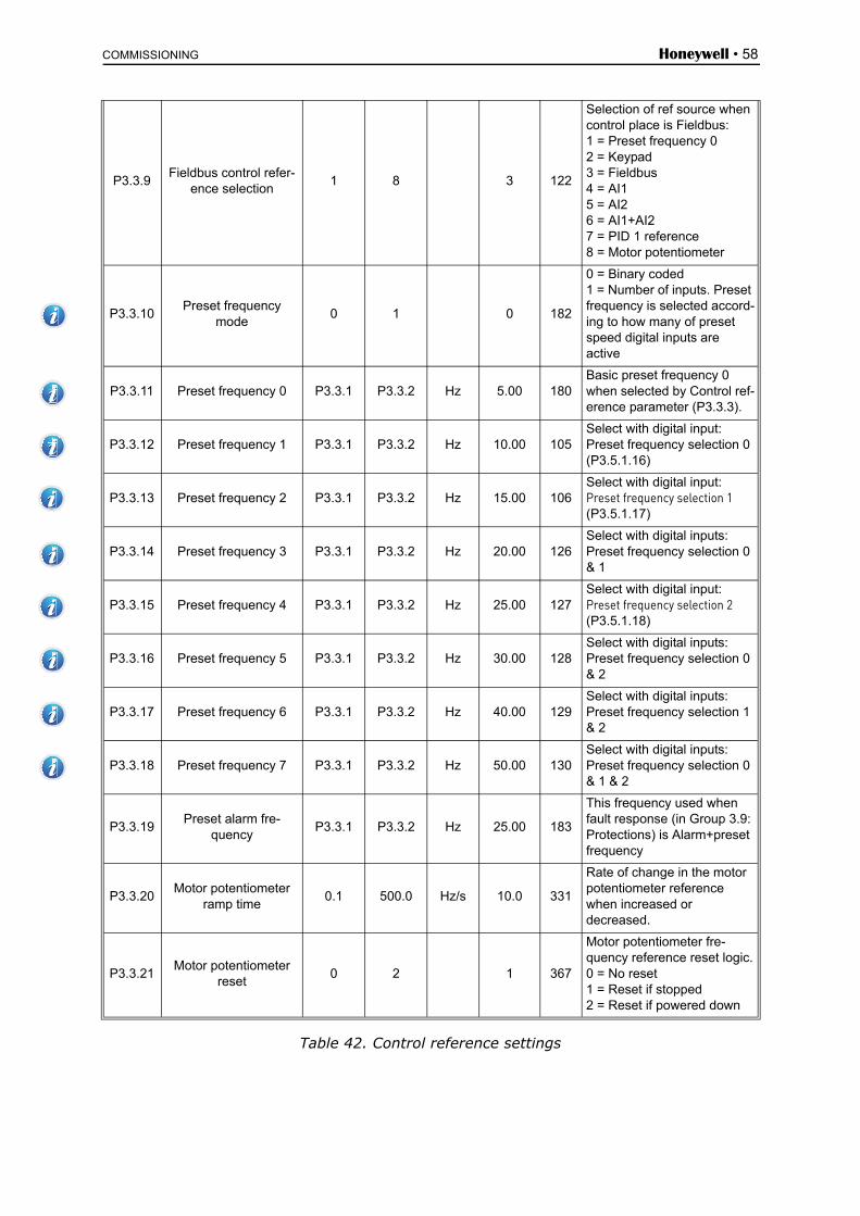
COMMISSIONING Honeywell • 58
Table 42. Control reference settings
P3.3.9Fieldbus control refer-
ence selection1 8 3 122
Selection of ref source when control place is Fieldbus:1 = Preset frequency 02 = Keypad3 = Fieldbus4 = AI15 = AI26 = AI1+AI27 = PID 1 reference8 = Motor potentiometer
P3.3.10Preset frequency
mode0 1 0 182
0 = Binary coded1 = Number of inputs. Preset frequency is selected accord-ing to how many of preset speed digital inputs are active
P3.3.11 Preset frequency 0 P3.3.1 P3.3.2 Hz 5.00 180Basic preset frequency 0 when selected by Control ref-erence parameter (P3.3.3).
P3.3.12 Preset frequency 1 P3.3.1 P3.3.2 Hz 10.00 105Select with digital input:Preset frequency selection 0 (P3.5.1.16)
P3.3.13 Preset frequency 2 P3.3.1 P3.3.2 Hz 15.00 106Select with digital input: Preset frequency selection 1 (P3.5.1.17)
P3.3.14 Preset frequency 3 P3.3.1 P3.3.2 Hz 20.00 126Select with digital inputs: Preset frequency selection 0 & 1
P3.3.15 Preset frequency 4 P3.3.1 P3.3.2 Hz 25.00 127Select with digital input: Preset frequency selection 2 (P3.5.1.18)
P3.3.16 Preset frequency 5 P3.3.1 P3.3.2 Hz 30.00 128Select with digital inputs: Preset frequency selection 0 & 2
P3.3.17 Preset frequency 6 P3.3.1 P3.3.2 Hz 40.00 129Select with digital inputs: Preset frequency selection 1 & 2
P3.3.18 Preset frequency 7 P3.3.1 P3.3.2 Hz 50.00 130Select with digital inputs: Preset frequency selection 0 & 1 & 2
P3.3.19Preset alarm fre-
quencyP3.3.1 P3.3.2 Hz 25.00 183
This frequency used when fault response (in Group 3.9: Protections) is Alarm+preset frequency
P3.3.20Motor potentiometer
ramp time0.1 500.0 Hz/s 10.0 331
Rate of change in the motor potentiometer reference when increased or decreased.
P3.3.21Motor potentiometer
reset0 2 1 367
Motor potentiometer fre-quency reference reset logic.0 = No reset1 = Reset if stopped2 = Reset if powered down
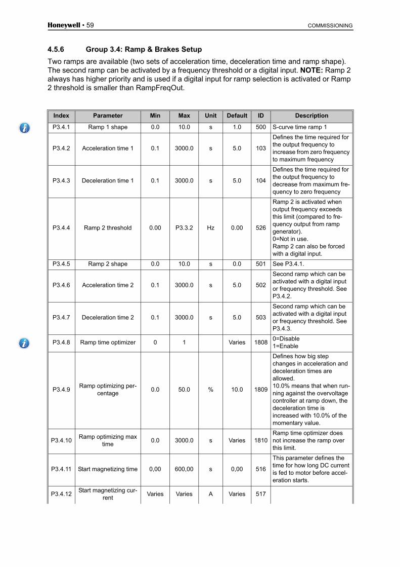
Honeywell • 59 COMMISSIONING
4.5.6 Group 3.4: Ramp & Brakes Setup
Two ramps are available (two sets of acceleration time, deceleration time and ramp shape). The second ramp can be activated by a frequency threshold or a digital input. NOTE: Ramp 2 always has higher priority and is used if a digital input for ramp selection is activated or Ramp 2 threshold is smaller than RampFreqOut.
Index Parameter Min Max Unit Default ID Description
P3.4.1 Ramp 1 shape 0.0 10.0 s 1.0 500 S-curve time ramp 1
P3.4.2 Acceleration time 1 0.1 3000.0 s 5.0 103
Defines the time required for the output frequency to increase from zero frequency to maximum frequency
P3.4.3 Deceleration time 1 0.1 3000.0 s 5.0 104
Defines the time required for the output frequency to decrease from maximum fre-quency to zero frequency
P3.4.4 Ramp 2 threshold 0.00 P3.3.2 Hz 0.00 526
Ramp 2 is activated when output frequency exceeds this limit (compared to fre-quency output from ramp generator).0=Not in use.Ramp 2 can also be forced with a digital input.
P3.4.5 Ramp 2 shape 0.0 10.0 s 0.0 501 See P3.4.1.
P3.4.6 Acceleration time 2 0.1 3000.0 s 5.0 502
Second ramp which can be activated with a digital input or frequency threshold. See P3.4.2.
P3.4.7 Deceleration time 2 0.1 3000.0 s 5.0 503
Second ramp which can be activated with a digital input or frequency threshold. See P3.4.3.
P3.4.8 Ramp time optimizer 0 1 Varies 18080=Disable1=Enable
P3.4.9Ramp optimizing per-
centage0.0 50.0 % 10.0 1809
Defines how big step changes in acceleration and deceleration times are allowed. 10.0% means that when run-ning against the overvoltage controller at ramp down, the deceleration time is increased with 10.0% of the momentary value.
P3.4.10Ramp optimizing max
time0.0 3000.0 s Varies 1810
Ramp time optimizer does not increase the ramp over this limit.
P3.4.11 Start magnetizing time 0,00 600,00 s 0,00 516
This parameter defines the time for how long DC current is fed to motor before accel-eration starts.
P3.4.12Start magnetizing cur-
rentVaries Varies A Varies 517

COMMISSIONING Honeywell • 60
Table 43. Ramp and brakes setup
P3.4.13DC braking time at
stop0,00 600,00 s 0,00 508
Determines if braking is ON or OFF and the braking time of the DC-brake when the motor is stopping.
P3.4.14 DC brake current Varies Varies A Varies 507
Defines the current injected into the motor during DC-braking. 0 = Disabled
P3.4.15Frequency to start DC braking at ramp stop
0,10 10,00 Hz 1,50 515The output frequency at which the DC-braking is applied.
P3.4.16 Flux braking 0 1 0 5200=Disabled1=Enabled
P3.4.17 Flux braking current 0 Varies A Varies 519Defines the current level for flux braking.

Honeywell • 61 COMMISSIONING
4.5.7 Group 3.5: I/O Configuration
4.5.7.1 Digital inputsDigital inputs are very flexible to use. Parameters are functions that are connected to the re-quired digital input terminal. The digital inputs are represented as, for example, DigIN Slot A.2, meaning the second input on slot A.
It is also possible to connect the digital inputs to time channels which are also represented as terminals.
Unless otherwise mentioned, all parameter functions are ON when the input is active (TRUE).
NOTE! The statuses of digital inputs and the digital output can be monitored in the Multi-monitoring view, see chapter 4.4.1.Default Settings can be made by using DigiIN Slot0.
Slot0.1= FALSE (=0V), Slot0.2 .... Slot0.9 = TRUE (=24VDC)
Index Parameter Default ID Description
P3.5.1.1 Control signal 1 A DigIN SlotA.1 403Start signal 1 when control place is I/O 1 (FWD)
P3.5.1.2 Control signal 2 A DigIn SlotA.2 404Start signal 2 when control place is I/O 1 (REV)
P3.5.1.3 Control signal 1 B DigIN Slot0.1 423 Start signal 1 when control place is I/O B
P3.5.1.4 Control signal 2 B DigIN Slot0.1 424 Start signal 2 when control place is I/O B
P3.5.1.5 I/O B control force DigIN Slot0.1 425 TRUE = Force the control place to I/O B
P3.5.1.6 I/O B reference force DigIN Slot0.1 343TRUE = Used frequency reference is speci-fied by I/O reference B parameter (P3.3.4).
P3.5.1.7 External fault close DigIN SlotA.3 405FALSE = OK TRUE = External fault
P3.5.1.8 External fault open DigIN Slot0.2 406FALSE = External faultTRUE = OK
P3.5.1.9 Fault reset DigIN SlotA.6 414 Resets all active faults
P3.5.1.10 Run enable DigIN Slot0.2 407 Must be on to set drive in Ready state
P3.5.1.11 Run interlock 1 DigIN Slot0.2 1041Drive may be ready but start is blocked as long as interlock contact is not TRUE.
P3.5.1.12 Run interlock 2 DigIn Slot0.2 1042 As above.
P3.5.1.13 Acceleration/Deceleration DigIN Slot0.1 408
Used for switching between ramps 1 and 2. FALSE=Ramp 1 shape, Acceleration time 1 and Deceleration time 1. TRUE=Ramp 2 shape, Acceleration time 2 and Deceleration time 2.
P3.5.1.14 Motor preheat ON DigIN Slot0.1 1044
FALSE = No actionTRUE = Uses the motor preheat DC-Current in Stop stateUsed when parameter P3.1.2.4 is set to 2.
P3.5.1.16 Preset Speed B0 DigIN SlotA.4 419Binary selector for Preset frequencies (0-7). See page 58.
P3.5.1.17 Preset Speed B1 DigIN SlotA.5 420Binary selector for Preset frequencies (0-7). See page 58.
P3.5.1.18 Preset Speed B2 DigIN Slot0.1 421Binary selector for Preset frequencies (0-7). See page 58.
P3.5.1.19 Timer 1 DigIN Slot0.1 447Rising edge starts Timer 1 programmed in Group 3.12: Timer functions parameter group
P3.5.1.20 Timer 2 DigIN Slot0.1 448 See above

COMMISSIONING Honeywell • 62
Table 44. Digital input settings
P3.5.1.21 Timer 3 DigIN Slot0.1 449 See above
P3.5.1.22 PID1 setpoint boost DigIN Slot0.1 1047FALSE = No boostTRUE = Boost
P3.5.1.23 PID1 select setpoint DigIN Slot0.1 1046FALSE = Setpoint 1TRUE = Setpoint 2
P3.5.1.24 PID2 start signal DigIN Slot0.2 1049
FALSE = PID2 in stop modeTRUE = PID2 regulatingThis parameter will have no effect if PID2 con-troller is not enabled in the Basic menu for PID2
P3.5.1.25 PID2 select setpoint DigIN Slot0.1 1048FALSE = Setpoint 1TRUE = Setpoint 2
P3.5.1.26 Motor 1 interlock DigIn Slot0.2 426FALSE = Not activeTRUE = Active
P3.5.1.27 Motor 2 interlock DigIN Slot0.1 427FALSE = Not activeTRUE = Active
P3.5.1.28 Motor 3 interlock DigIN Slot0.1 428FALSE = Not activeTRUE = Active
P3.5.1.29 Motor 4 interlock DigIN Slot0.1 429FALSE = Not activeTRUE = Active
P3.5.1.30 Interlock 5 DigIN Slot0.1 430FALSE = Not activeTRUE = Active
P3.5.1.31Reset Maintenance
counter 1DigIN Slot0.1 490 TRUE = Reset
P3.5.1.32Reset Maintenance
counter 2DigIN Slot0.1 491 TRUE = Reset
P3.5.1.33Reset Maintenance
counter 3DigIN Slot0.1 492 TRUE = Reset
P3.5.1.36 Motor potentiometer UP DigIN Slot0.1 418
FALSE = Not activeTRUE = Active (Motor potentiometer reference INCREASES until the contact is opened)
P3.5.1.37Motor potentiometer
DOWNDigIN Slot0.1 417
FALSE = Not activeTRUE = Active (Motor potentiometer reference DECREASES until the contact is opened)
P3.5.1.38 FireMode PresetFreqSel0 DigIn Slot0.1 15531 Fire Mode prset frequency selection.
P3.5.1.39 FireMode PresetFreqSel1 DigIn Slot0.1 15532 Fire Mode preset frequency selection.

Honeywell • 63 COMMISSIONING
4.5.7.2 Analog inputs
Index Parameter Min Max Unit Default ID Description
P3.5.2.1 AI1 signal selectionAnIN
SlotA.1377
Connect the AI1 signal to the analog input of your choice with this parameter. Programmable.
P3.5.2.2 AI1 signal filter time 0.00 300.00 s 0.1 378 Filter time for analog input
P3.5.2.3 AI1 signal range 0 1 0 3790 = 0…10V / 0…20mA1 = 2…10V / 4…20mA
P3.5.2.4 AI1 custom. min -160.00 160.00 % 0.00 380Custom range min setting20% = 4-20 mA/2-10 V
P3.5.2.5 AI1 custom. max -160.00 160.00 % 100.00 381 Custom range max setting
P3.5.2.6 AI1 signal inversion 0 1 0 3870 = Normal1 = Signal inverted
P3.5.2.7 AI2 signal selectionAnIN
SlotA.2388 See P3.5.2.1.
P3.5.2.8 AI2 signal filter time 0.00 300.00 s 0.1 389 See P3.5.2.2.
P3.5.2.9 AI2 signal range 0 1 1 3900 = 0…10V / 0…20mA1 = 2…10V / 4…20mA
P3.5.2.10 AI2 custom. min -160.00 160.00 % 0.00 391 See P3.5.2.4.
P3.5.2.11 AI2 custom. max -160.00 160.00 % 100.00 392 See P3.5.2.5.
P3.5.2.12 AI2 signal inversion 0 1 0 398 See P3.5.2.6.
P3.5.2.13 AI3 signal selectionAnIN
Slot0.1141
Connect the AI3 signal to the analog input of your choice with this parameter. Programmable.
P3.5.2.14 AI3 signal filter time 0.00 300.00 s 0.1 142 Filter time for analog input
P3.5.2.15 AI3 signal range 0 1 0 1430 = 0…10V / 0…20mA1 = 2…10V / 4…20mA
P3.5.2.16 AI3 custom. min -160.00 160.00 % 0.00 144 20% = 4-20 mA/2-10 V
P3.5.2.17 AI3 custom. max -160.00 160.00 % 100.00 145 Custom range max setting
P3.5.2.18 AI3 signal inversion 0 1 0 1510 = Normal1 = Signal inverted
P3.5.2.19 AI4 signal selectionAnIN
Slot0.1152
See P3.5.2.13. Programma-ble.
P3.5.2.20 AI4 signal filter time 0.00 300.00 s 0.1 153 See P3.5.2.14.
P3.5.2.21 AI4 signal range 0 1 0 1540 = 0…10V / 0…20mA1 = 2…10V / 4…20mA
P3.5.2.22 AI4 custom. min -160.00 160.00 % 0.00 155 See P3.5.2.16.
P3.5.2.23 AI4 custom. max -160.00 160.00 % 100.00 156 See P3.5.2.17.
P3.5.2.24 AI4 signal inversion 0 1 0 162 See P3.5.2.18.
P3.5.2.25 AI5 signal selectionAnIN
Slot0.1188
Connect the AI5 signal to the analog input of your choice with this parameter. Programmable.
P3.5.2.26 AI5 signal filter time 0.00 300.00 s 0.1 189 Filter time for analog input
P3.5.2.27 AI5 signal range 0 1 0 1900 = 0…10V / 0…20mA1 = 2…10V / 4…20mA
P3.5.2.28 AI5 custom. min -160.00 160.00 % 0.00 191 20% = 4-20 mA/2-10 V
P3.5.2.29 AI5 custom. max -160.00 160.00 % 100.00 192 Custom range max setting

COMMISSIONING Honeywell • 64
Table 45. Analog input settings
P3.5.2.30 AI5 signal inversion 0 1 0 1980 = Normal1 = Signal inverted
P3.5.2.31 AI6 signal selectionAnIN
Slot0.1199
See P3.5.2.13. Programma-ble.
P3.5.2.32 AI6 signal filter time 0.00 300.00 s 0.1 200 See P3.5.2.14.
P3.5.2.33 AI6 signal range 0 1 0 2010 = 0…10V / 0…20mA1 = 2…10V / 4…20mA
P3.5.2.34 AI6 custom. min -160.00 160.00 % 0.00 202 See P3.5.2.16.
P3.5.2.35 AI6 custom. max -160.00 160.00 % 100.00 203 See P3.5.2.17.
P3.5.2.36 AI6 signal inversion 0 1 0 209 See P3.5.2.18.

Honeywell • 65 COMMISSIONING
4.5.7.3 Digital outputs, slot B (Basic)
Table 46. Digital output settings on basic I/O board
Index Parameter Min Max Unit Default ID Description
P3.5.3.2.1 Basic RO1 function 0 36 2 11001
Function selection for Basic R01:0 = None1 = Ready2 = Run3 = General fault4 = General fault inverted5 = General alarm6 = Reversed7 = At speed8 = Motor regulator active9 = Preset speed active10 = Keypad control active11 = I/O B control activated12 = Limit supervision 113 = Limit supervision 214 = Start signal active15 = Reserved16 = Fire Mode activation17 = RTC time chnl 1 control18 = RTC time chnl 2 control19 = RTC time chnl 3 control20 = FB ControlWord B1321 = FB ControlWord B1422 = FB ControlWord B1523 = PID1 in Sleep mode24 = Reserved25 = PID1 supervision limits26 = PID2 supervision limits27 = Motor 1 control28 = Motor 2 control29 = Motor 3 control30 = Motor 4 control31 = Motor 5 control32 = Reserved (Always open)33 = Reserved (Always open)34 = Maintenance alarm35 = Maintenance fault36 = Thermistor fault37 = Motor Switch
P3.5.3.2.2 Basic R01 ON delay 0.00 320.00 s 0.00 11002 ON delay for relay
P3.5.3.2.3 Basic R01 OFF delay 0.00 320.00 s 0.00 11003 OFF delay for relay
P3.5.3.2.4 Basic R02 function 0 39 3 11004 See P3.5.3.2.1
P3.5.3.2.5 Basic R02 ON delay 0.00 320.00 s 0.00 11005 See P3.5.3.2.2.
P3.5.3.2.6 Basic R02 OFF delay 0.00 320.00 s 0.00 11006 See P3.5.3.2.3.
P3.5.3.2.7 Basic R03 function 0 39 1 11007See P3.5.3.2.1.Not visible if only 2 output relays are installed
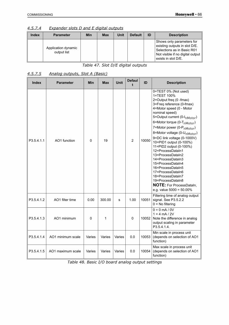
COMMISSIONING Honeywell • 66
4.5.7.4 Expander slots D and E digital outputs
Table 47. Slot D/E digital outputs
4.5.7.5 Analog outputs, Slot A (Basic)
Table 48. Basic I/O board analog output settings
Index Parameter Min Max Unit Default ID Description
Application dynamic output list
Shows only parameters for existing outputs in slot D/E.Selections as in Basic R01Not visible if no digital output exists in slot D/E.
Index Parameter Min Max UnitDefaul
tID Description
P3.5.4.1.1 AO1 function 0 19 2 10050
0=TEST 0% (Not used)1=TEST 100%2=Output freq (0 -fmax)3=Freq reference (0-fmax)4=Motor speed (0 - Motor nominal speed)5=Output current (0-InMotor)
6=Motor torque (0-TnMotor)
7=Motor power (0-PnMotor)
8=Motor voltage (0-UnMotor)
9=DC link voltage (0-1000V)10=PID1 output (0-100%)11=PID2 output (0-100%)12=ProcessDataIn113=ProcessDataIn214=ProcessDataIn315=ProcessDataIn416=ProcessDataIn517=ProcessDataIn618=ProcessDataIn719=ProcessDataIn8NOTE: For ProcessDataIn, e.g. value 5000 = 50.00%
P3.5.4.1.2 AO1 filter time 0.00 300.00 s 1.00 10051Filtering time of analog output signal. See P3.5.2.20 = No filtering
P3.5.4.1.3 AO1 minimum 0 1 0 10052
0 = 0 mA / 0V1 = 4 mA / 2VNote the difference in analog output scaling in parameter P3.5.4.1.4.
P3.5.4.1.4 AO1 minimum scale Varies Varies Varies 0.0 10053Min scale in process unit (depends on selection of AO1 function)
P3.5.4.1.5 AO1 maximum scale Varies Varies Varies 0.0 10054Max scale in process unit (depends on selection of AO1 function)

Honeywell • 67 COMMISSIONING
4.5.7.6 Expander slots D to E analog outputs
Table 49. Slot D/E analog outputs
Index Parameter Min Max Unit Default ID Description
Application dynamic output list
Shows only parameters for existing outputs in slot D/E.Selections as in Basic AO1Not visible if no analog out-put exists in slot D/E.

COMMISSIONING Honeywell • 68
4.5.8 Group 3.6: Fieldbus Data Mapping
The fieldbus data mapping is used in some communication protocols. Please read the fieldbus manuals for more details.
Table 50. Fieldbus data mapping
Fieldbus process data out
Values to monitor through fieldbus are:
Table 51. Fieldbus Process Data Out
Index Parameter Min Max Unit Default ID Description
P3.6.1Fieldbus data out 1
selection0 35000 1 852
Data sent to fieldbus can be chosen with parameter and monitor value ID numbers. The data is scaled to unsigned 16-bit format according to the format on keypad. E.g. 25.5 on keypad equals 255.
P3.6.2Fieldbus data out 2
selection0 35000 2 853
Select Process Data Out with parameter ID
P3.6.3Fieldbus data out 3
selection0 35000 3 854
Select Process Data Out with parameter ID
P3.6.4Fieldbus data out 4
selection0 35000 4 855
Select Process Data Out with parameter ID
P3.6.5Fieldbus data out 5
selection0 35000 5 856
Select Process Data Out with parameter ID
P3.6.6Fieldbus data out 6
selection0 35000 6 857
Select Process Data Out with parameter ID
P3.6.7Fieldbus data out 7
selection0 35000 7 858
Select Process Data Out with parameter ID
P3.6.8Fieldbus data out 8
selection0 35000 37 859
Select Process Data Out with parameter ID
Data Value Scale
Process Data Out 1 Output frequency 0.01 Hz
Process Data Out 2 Motor speed 1 rpm
Process Data Out 3 Motor current 0.1 A
Process Data Out 4 Motor torque 0.1 %
Process Data Out 5 Motor power 0.1 %
Process Data Out 6 Motor voltage 0.1 V
Process Data Out 7 DC-link voltage 1 V
Process Data Out 8 Last active fault code

Honeywell • 69 COMMISSIONING
4.5.9 Group 3.7: Prohibit Frequencies
In some systems it may be necessary to avoid certain frequencies due to mechanical reso-nance problems. By setting up prohibit frequencies it is possible to skip these ranges.
Table 52. Prohibit frequencies
Index Parameter Min Max Unit Default ID Description
P3.7.1Prohibit frequency range 1 low limit
-1 320 Hz 0 509 0 = Not used
P3.7.2Prohibit frequency range 1 high limit
0 320 Hz 0 510 0 = Not used
P3.7.3Prohibit frequency range 2 low limit
0 320 Hz 0 511 0 = Not used
P3.7.4Prohibit frequency range 2 high limit
0 320 Hz 0 512 0 = Not used
P3.7.5Prohibit frequency range 3 low limit
0 320 Hz 0 513 0 = Not used
P3.7.6Prohibit frequency range 3 high limit
0 320 Hz 0 514 0 = Not used
P3.7.7 Ramp time factor 0.1 10 Times 1 518Multiplier of the currently selected ramp time between prohibit frequency limits.
P3.7.8Resonance sweep
ramp0.1 3000 s 60 1812
How fast the resonance sweep should sweep through the frequency range.
P3.7.9 Resonance sweep 0 1 0 18110 = Inactive1 = Activate

COMMISSIONING Honeywell • 70
4.5.10 Group 3.8: Limit supervisions
The limit supervision can be used to activate the relay outputs (P3.5.3.2.ff). The relays are linked with the setting "12 LimSuperv1” and with the setting "13 LimSuperv2”.
Choose here:
1. One or two (P3.8.1/P3.8.5) signal values for supervision.2. Whether the low or high limits are supervised (P3.8.2/P3.8.6)3. The actual limit values (P3.8.3/P3.8.7).4. The hystereses for the set limit values (P3.8.4/P3.8.8).
Table 53. Limits supervision settings
Index Parameter Min Max Unit Default ID Description
P3.8.1Supervision #1 item
selection0 7 0 1431
0 = Output frequency1 = Frequency reference2 = Motor current3 = Motor torque4 = Motor power5 = DC-link voltage6 = Analog input 17 = Analog input 2
P3.8.2 Supervision #1 mode 0 2 0 1432
0 = Not used1 = Low limit supervision(output active over limit)2 = High limit supervision(output active under limit)
P3.8.3 Supervision #1 limit -200.000 200.000 Varies 25.00 1433Supervision limit for selected item. Unit appears automati-cally.
P3.8.4Supervision #1 limit
hysteresis-200.000 200.000 Varies 5.00 1434
Supervision limit hysteresis for selected item. Unit is set automatically.
P3.8.5Supervision #2 item
selection0 7 1 1435 See P3.8.1
P3.8.6 Supervision #2 mode 0 2 0 1436 See P3.8.2
P3.8.7 Supervision #2 limit -200.000 200.000 Varies 40.00 1437 See P3.8.3
P3.8.8Supervision #2 limit
hysteresis-200.000 200.000 Varies 5.00 1438 See P3.8.4
Honeywell • 71 COMMISSIONING
4.5.11 Group 3.9: Protections
Parameters of motor thermal protection (P3.9.6 to P3.9.10)
The motor thermal protection is to protect the motor from overheating. The drive is capable of supplying higher than nominal current to the motor. If the load requires this high current there is a risk that the motor will be thermally overloaded. This is the case especially at low frequen-cies. At low frequencies the cooling effect of the motor is reduced as well as its capacity. If the motor is equipped with an external fan the load reduction at low speeds is small.
The motor thermal protection is based on a calculated model and it uses the output current of the drive to determine the load on the motor.
The motor thermal protection can be adjusted with parameters. The thermal current IT specifies the load current above which the motor is overloaded. This current limit is a function of the out-put frequency.
The thermal stage of the motor can be monitored on the control keypad display. See chapter 4.4.
Parameters of Stall protection (P3.9.11 to P3.9.14)
The motor stall protection protects the motor from short time overload situations such as one caused by a stalled shaft. The reaction time of the stall protection can be set shorter than that of motor thermal protection. The stall state is defined with two parameters, P3.9.12 (Stall cur-rent) and P3.9.14 (Stall frequency limit). If the current is higher than the set limit and the output frequency is lower than the set limit the stall state is true. There is actually no real indication of the shaft rotation. Stall protection is a type of overcurrent protection.
Parameters of Underload protection (P3.9.15 to P3.9.18)
The purpose of the motor underload protection is to ensure that there is load on the motor when the drive is running. If the motor loses its load there might be a problem in the process, e.g. a broken belt or a dry pump.
Motor underload protection can be adjusted by setting the underload curve with parameters P3.9.16 (Underload protection: Field weakening area load) and P3.9.17 (Underload protec-tion: Zero frequency load), see below. The underload curve is a squared curve set between the zero frequency and the field weakening point. The protection is not active below 5Hz (the underload time counter is stopped).
If you use long motor cables (max. 100m / 328 ft) together with small drives (≤1.5 kW / 2.0 HP) the motor current measured by the drive can be much higher than the actual motor cur-rent due to capacitive currents in the motor cable. Consider this when setting up the motor thermal protection functions.
The calculated model does not protect the motor if the airflow to the motor is reduced by blocked air intake grill. If the control board is powered off, the model is initialised based on the value which had been calculated before the power off (memory functionality).
If you use long motor cables (max. 100m / 328 ft) together with small drives (≤1.5 kW / 2.0 HP) the motor current measured by the drive can be much higher than the actual motor cur-rent due to capacitive currents in the motor cable. Con-sider this when setting up the motor thermal protection functions.
13006.emf
13006.emf
13006.emf
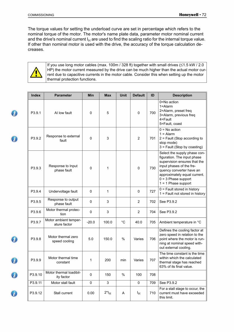
COMMISSIONING Honeywell • 72
The torque values for setting the underload curve are set in percentage which refers to the nominal torque of the motor. The motor's name plate data, parameter motor nominal current and the drive's nominal current IH are used to find the scaling ratio for the internal torque value. If other than nominal motor is used with the drive, the accuracy of the torque calculation de-creases.
If you use long motor cables (max. 100m / 328 ft) together with small drives (≤1.5 kW / 2.0 HP) the motor current measured by the drive can be much higher than the actual motor cur-rent due to capacitive currents in the motor cable. Consider this when setting up the motor thermal protection functions.
Index Parameter Min Max Unit Default ID Description
P3.9.1 AI low fault 0 5 0 700
0=No action1=Alarm2=Alarm, preset freq3=Alarm, previous freq4=Fault5=Fault, coast
P3.9.2Response to external
fault0 3 2 701
0 = No action1 = Alarm2 = Fault (Stop according to stop mode)3 = Fault (Stop by coasting)
P3.9.3Response to Input
phase fault0 1 0 730
Select the supply phase con-figuration. The input phase supervision ensures that the input phases of the fre-quency converter have an approximately equal current.0 = 3 Phase support1 = 1 Phase support
P3.9.4 Undervoltage fault 0 1 0 7270 = Fault stored in history1 = Fault not stored in history
P3.9.5Response to output
phase fault0 3 2 702 See P3.9.2
P3.9.6Motor thermal protec-
tion0 3 2 704 See P3.9.2
P3.9.7Motor ambient temper-
ature factor-20.0 100.0 °C 40.0 705 Ambient temperature in °C
P3.9.8Motor thermal zero
speed cooling5.0 150.0 % Varies 706
Defines the cooling factor at zero speed in relation to the point where the motor is run-ning at nominal speed with-out external cooling.
P3.9.9Motor thermal time
constant1 200 min Varies 707
The time constant is the time within which the calculated thermal stage has reached 63% of its final value.
P3.9.10Motor thermal loadibil-
ity factor0 150 % 100 708
P3.9.11 Motor stall fault 0 3 0 709 See P3.9.2
P3.9.12 Stall current 0.00 2*IH A IH 710For a stall stage to occur, the current must have exceeded this limit.
13006.emf

Honeywell • 73 COMMISSIONING
Table 54. Protections settings
P3.9.13 Stall time limit 1.00 120.00 s 15.00 711This is the maximum time allowed for a stall stage.
P3.9.14 Stall frequency limit 1.00 P3.3.2 Hz 25.00 712
For a stall state to occur, the output frequency must have remained below this limit for a certain time.
P3.9.15Underload fault (bro-ken belt/dry pump)
0 3 0 713 See P3.9.2
P3.9.16Underload protection: Field weakening area
load10.0 150.0 % 50.0 714
This parameter gives the value for the minimum torque allowed when the output fre-quency is above the field weakening point.
P3.9.17Underload protection: Zero frequency load
5.0 150.0 % 10.0 715
This parameter gives value for the minimum torque allowed with zero frequency.If you change the value of parameter P3.1.1.4 this parameter is automatically restored to the default value.
P3.9.18Underload protection:
Time limit2.00 600.00 s 20.00 716
This is the maximum time allowed for an underload state to exist.
P3.9.19Response to Fieldbus communication fault
0 4 3 733 See P3.9.1
P3.9.20Slot communication
fault0 3 2 734 See P3.9.2
P3.9.21 Thermistor fault 0 3 0 732 See P3.9.2
P3.9.22 Soft fill timeout 0 3 2 748 See P3.9.2
P3.9.23Response to PID1 supervision fault
0 3 2 749 See P3.9.2
P3.9.24Response to PID2 supervision fault
0 3 2 757 See P3.9.2
P3.9.25Temperature fault sig-
nal0 6 739
0 = Not Used1 = TempInput 12 = TempInput 23 = TempInput 34 = TempInput 1-25 = TempInput 2-36 = TempInput 1-3
P3.9.26 TempAlarm Limit -30.0 200.0 °C/°F 741Temperature for triggering an alarm.
P3.9.27 TempFault Limit -30.0 200.0 °C/°F 742Temperature for triggering a fault.
P3.9.28Temperature fault
response0 200.03 740
0 = No action1 = Alarm2 = Fault3 = Fault, coast

COMMISSIONING Honeywell • 74
4.5.12 Group 3.10: Automatic reset
Table 55. Autoreset settings
Index Parameter Min Max Unit Default ID Description
P3.10.1 Automatic reset 0 1 0 7310 = Disabled1 = Enabled
P3.10.2 Restart function 0 1 1 719
The start mode for Automatic reset is selected with this parameter:0 = Flying start1 = According to par. P3.2.4
P3.10.3 Wait time 0,10 10000,0 s 0,50 717Wait time before the first reset is executed.
P3.10.4Automatic reset: Trial
time0,00 10000,0 s 60,00 718
When the trial time has elapsed, and the fault is still active, the drive will trip to fault.
P3.10.5 Number of trials 1 10 4 759NOTE: Total number of trials (irrespective of fault type)
P3.10.6Autoreset:
Undervoltage0 1 1 720
Autoreset permitted?0 = No1 = Yes
P3.10.7Autoreset:
Overvoltage0 1 1 721
Autoreset permitted?0 = No1 = Yes
P3.10.8Autoreset:
Overcurrent0 1 1 722
Autoreset permitted?0 = No1 = Yes
P3.10.9 Autoreset: AI low 0 1 1 723Autoreset permitted?0 = No1 = Yes
P3.10.10Autoreset: Unit over-
temperature0 1 1 724
Autoreset permitted?0 = No1 = Yes
P3.10.11Autoreset: Motor over-
temperature0 1 1 725
Autoreset permitted?0 = No1 = Yes
P3.10.12Autoreset:
External fault0 1 0 726
Autoreset permitted?0 = No1 = Yes
P3.10.13Autoreset:
Underload fault0 1 0 738
Autoreset permitted?0 = No1 = Yes

Honeywell • 75 COMMISSIONING
4.5.13 Group 3.11: Application Settings
Table 56. Application settings
Index Parameter Min Max Unit Default ID Description
M3.11.1 C°/F° selection 0 1 0 11970 = C°1 = F°
M3.11.2 kW/HP selection 0 1 0 11980 = kW1 = HP

COMMISSIONING Honeywell • 76
4.5.14 Group 3.12: Timer functions
The functions of this parameter group can be made the fullest advantage of if the Real Time . Clock settings have been properly made in Parameters P5.5.ff.
You can program up to five incidents to take place between set points of time (Intervals) and additionally three timer-based functions to last for a set period of time.
Intervals and Timers are assigned to the three available Time Channels .
Example of programming: You want to apply Preset frequency 1 (M3.3.11, set to use with parameter
M3.5.1.15, Preset frequency selection 0) Mondays, from 08:00 until 16:00 hrs .
1. Set the parameters for Interval 1 (3.12.1):M3.12.1.3: From day: ‘1’ (=Monday)M3.12.1.1: ON time: ‘0800’
M3.12.1.2: OFF time: ‘1600’M3.12.1.4: To day: ‘1’ (=Monday)
M3.12.1.5: Assign to channel: ‘1’ (= Time Channel 1)
2. Then assign the selected Time channel to a digital input using the programming method described in chapter 4.5.2.Go to menu Parameters (M3), further down to menu I/O config (M3.5) and Digital inputs (M3.5.1). Locate the parameter Preset frequency selection 0 (M3.5.1.15). Change the value of this parameter to TimeChannel.1.
Now the function Preset frequency selection 0 is activated at 08:00 on Monday and deactivated at 16:00 the same day.
The status of the Intervals and Time channels can be monitored in Menu M2.3.
Index Parameter Min Max Unit Default ID Description
3.12.1 INTERVAL 1
P3.12.1.1 ON time 00:00:00 23:59:59 hh:mm:ss 00:00:00 1464 ON time
P3.12.1.2 OFF time 00:00:00 23:59:59 hh:mm:ss 00:00:00 1465 OFF time
P3.12.1.3 From day 0 6 0 1466
ON day of week0=Sunday1=Monday2=Tuesday3=Wednesday4=Thursday5=Friday6=Saturday
P3.12.1.4 To day 0 6 0 1467 See above
P3.12.1.5 Assign to channel 0 3 0 1468
Select affected time channel (1-3)0=Not used1=Time channel 12=Time channel 23=Time channel 3
3.12.2 INTERVAL 2
P3.12.2.1 ON time 00:00:00 23:59:59 hh:mm:ss 00:00:00 1469 See Interval 1
P3.12.2.2 OFF time 00:00:00 23:59:59 hh:mm:ss 00:00:00 1470 See Interval 1
P3.12.2.3 From day 0 6 0 1471 See Interval 1

Honeywell • 77 COMMISSIONING
Table 57. Timer functions
P3.12.2.4 To day 0 6 0 1472 See Interval 1
P3.12.2.5 Assign to channel 0 3 0 1473 See Interval 1
3.12.3 INTERVAL 3
P3.12.3.1 ON time 00:00:00 23:59:59 hh:mm:ss 00:00:00 1474 See Interval 1
P3.12.3.2 OFF time 00:00:00 23:59:59 hh:mm:ss 00:00:00 1475 See Interval 1
P3.12.3.3 From day 0 6 0 1476 See Interval 1
P3.12.3.4 To day 0 6 0 1477 See Interval 1
P3.12.3.5 Assign to channel 0 3 0 1478 See Interval 1
3.12.4 INTERVAL 4
P3.12.4.1 ON time 00:00:00 23:59:59 hh:mm:ss 00:00:00 1479 See Interval 1
P3.12.4.2 OFF time 00:00:00 23:59:59 hh:mm:ss 00:00:00 1480 See Interval 1
P3.12.4.3 From day 0 6 0 1481 See Interval 1
P3.12.4.4 To day 0 6 0 1482 See Interval 1
P3.12.4.5 Assign to channel 0 3 0 1483 See Interval 1
3.12.5 INTERVAL 5
P3.12.5.1 ON time 00:00:00 23:59:59 hh:mm:ss 00:00:00 1484 See Interval 1
P3.12.5.2 OFF time 00:00:00 23:59:59 hh:mm:ss 00:00:00 1485 See Interval 1
P3.12.5.3 From day 0 6 0 1486 See Interval 1
P3.12.5.4 To day 0 6 0 1487 See Interval 1
P3.12.5.5 Assign to channel 0 3 0 1488 See Interval 1
3.12.6 TIMER 1
P3.12.6.1 Duration 0 72000 s 0 1489The time the timer will run when activated. (Activated by DI)
P3.12.6.2 Assign to channel 0 3 0 1490
Select affected time channel (1-3)0=Not used1=Time channel 12=Time channel 23=Time channel 3
3.12.7 TIMER 2
P3.12.7.1 Duration 0 72000 s 0 1491 See Timer 1
P3.12.7.2 Assign to channel 0 3 0 1492 See Timer 1
3.12.8 TIMER 3
P3.12.8.1 Duration 0 72000 s 0 1493 See Timer 1
P3.12.8.2 Assign to channel 0 3 0 1494 See Timer 1

COMMISSIONING Honeywell • 78
4.5.15 Group 3.13: PID-controller 1
4.5.15.1 Basic settings
Table 58.
Index Parameter Min Max Unit Default ID Description
P3.13.1.1 PID gain 0.00 1000.00 % 100.00 118
If the value of the parameter is set to 100% a change of 10% in the error value causes the controller output to change by 10%.
P3.13.1.2 PID integration time 0.00 600.00 s 1.00 119
If this parameter is set to 1,00 second a change of 10% in the error value causes the controller output to change by 10.00%/s.
P3.13.1.3 PID derivation time 0.00 100.00 s 0.00 132
If this parameter is set to 1,00 second a change of 10% in the error value during 1.00 s causes the controller output to change by 10.00%.
P3.13.1.4 Process unit selection 1 38 1 1036 Select unit for actual value.
P3.13.1.5 Process unit min Varies Varies Varies 0 1033
P3.13.1.6 Process unit max Varies Varies Varies 100 1034
P3.13.1.7 Process unit decimals 0 4 2 1035Number of decimals for pro-cess unit value
P3.13.1.8 Error inversion 0 1 0 340
0 = Normal (Feedback < Set-point -> Increase PID output)1 = Inverted (Feedback < Setpoint -> Decrease PID out-put)
P3.13.1.9 Dead band hysteresis Varies Varies Varies 0 1056
Dead band area around the setpoint in process units.The PID output is locked if the feedback stays within the deadband area for a pre-defined time.
P3.13.1.10 Dead band delay 0.00 320.00 s 0.00 1057
If the feedback stays within the dead band area for a pre-defined time, the output is locked.

Honeywell • 79 COMMISSIONING
4.5.15.2 Setpoints
Index Parameter Min Max Unit Default ID Description
P3.13.2.1 Keypad setpoint 1 Varies Varies Varies 0 167
P3.13.2.2 Keypad setpoint 2 Varies Varies Varies 0 168
P3.13.2.3 Setpoint ramp time 0.00 300.0 s 0.00 1068
Defines the rising and falling ramp times for setpoint changes. (Time to change from minimum to maximum)
P3.13.2.4Setpoint source 1
selection0 16 1 332
0 = Not used1 = Keypad setpoint 12 = Keypad setpoint 23 = AI14 = AI25 = AI36 = AI47 = AI58 = AI69 = ProcessDataIn110 = ProcessDataIn211 = ProcessDataIn312 = ProcessDataIn413 = ProcessDataIn514 = ProcessDataIn615 = ProcessDataIn716 = ProcessDataIn817 = Temp.Input 118 = Temp.Input 219 = Temp.Input 3AI’s, ProcessDataIn and Temp.input are handled as percent (0.00-100.00%) and scaled according to Setpoint minimum and maximum. NOTE: ProcessDataIn use two decimals.
P3.13.2.5 Setpoint 1 minimum -200.00 200.00 % 0.00 1069Minimum value at analog sig-nal minimum.
P3.13.2.6 Setpoint 1 maximum -200.00 200.00 % 100.00 1070Maximum value at analog signal maximum.
P3.13.2.7 Sleep frequency limit 1 0.00 320.00 Hz 0.00 1016
Drive goes to sleep mode when the output frequency stays below this limit for a time greater than that defined by parameter Sleep delay.
P3.13.2.8 Sleep delay 1 0 3000 s 0 1017
The minimum amount of time the frequency has to remain below the Sleep level before the drive is stopped.
P3.13.2.9 Wake-up level 1 Varies 0.0000 1018
Defines the level for the PID feedback value wake-up supervision. Uses selected process units.
P3.13.2.10 Setpoint 1 boost -2.0 2.0 x 1.0 1071The setpoint can be boosted with a digital input.
P3.13.2.11Setpoint source 2
selection0 16 2 431 See par. P3.13.2.4

COMMISSIONING Honeywell • 80
Table 59.
P3.13.2.12 Setpoint 2 minimum -200.00 200.00 % 0.00 1073Minimum value at analog sig-nal minimum.
P3.13.2.13 Setpoint 2 maximum -200.00 200.00 % 100.00 1074Maximum value at analog signal maximum.
P3.13.2.14 Sleep frequency limit 2 0.00 320.00 Hz 0.00 1075 See P3.13.2.7.
P3.13.2.15 Sleep delay 2 0 3000 s 0 1076 See P3.13.2.8.
P3.13.2.16 Wake-up level 2 Varies 0.0000 1077 See P3.13.2.9.
P3.13.2.17 Setpoint 2 boost -2.0 2.0 x 1.0 1078 See P3.13.2.10.

Honeywell • 81 COMMISSIONING
4.5.15.3 Feedbacks
Table 60.
Index Parameter Min Max Unit Default ID Description
P3.13.3.1 Feedback function 1 9 1 333
1=Only Source1 in use2=SQRT(Source1);(Flow=Constant x SQRT(Pressure))3=SQRT(Source1- Source 2)4=SQRT(Source 1) + SQRT (Source 2)5=Source 1 + Source 26=Source 1 - Source 27=MIN (Source 1, Source 2)8=MAX (Source 1, Source 2)9=MEAN (Source1, Source2)
P3.13.3.2Feedback function
gain-1000.0 1000.0 % 100.0 1058
Used e.g. with selection 2 in Feedback function
P3.13.3.3Feedback 1 source
selection0 14 2 334
0 = Not used1 = AI12 = AI23 = AI34 = AI45 = AI56 = AI67 = ProcessDataIn18 = ProcessDataIn29 = ProcessDataIn310 = ProcessDataIn411 = ProcessDataIn512 = ProcessDataIn613 = ProcessDataIn714 = ProcessDataIn815 = Temp.Input 116 = Temp.Input 217 = Temp.Input 3AI’s, ProcessDataIn and Temp.input are handled as % (0.00-100.00%) and scaled according to Feedback min and max. NOTE: ProcessDataIn use two decimals.
P3.13.3.4 Feedback 1 minimum -200.00 200.00 % 0.00 336Minimum value at analog sig-nal minimum.
P3.13.3.5 Feedback 1 maximum -200.00 200.00 % 100.00 337Maximum value at analog signal maximum.
P3.13.3.6Feedback 2
source selection0 14 0 335 See P3.13.3.3
P3.13.3.7 Feedback 2 minimum -200.00 200.00 % 0.00 338Minimum value at analog sig-nal minimum.
P3.13.3.8 Feedback 2 maximum -200.00 200.00 % 100.00 339Maximum value at analog signal maximum.
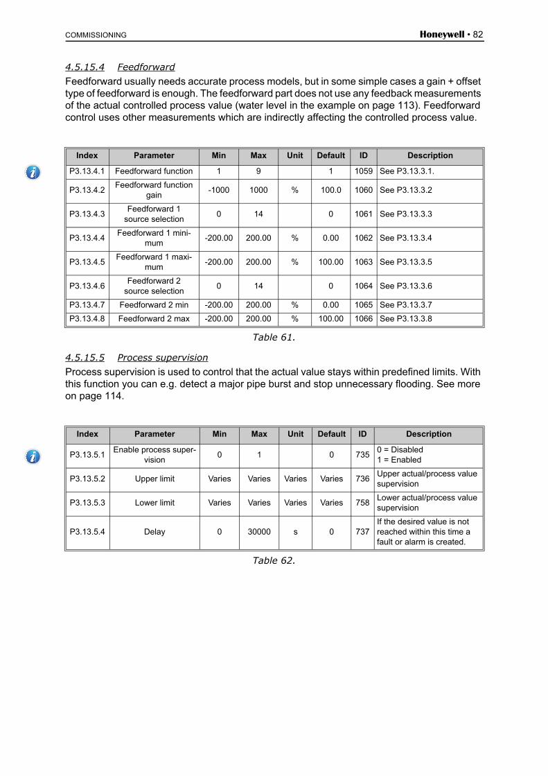
COMMISSIONING Honeywell • 82
4.5.15.4 FeedforwardFeedforward usually needs accurate process models, but in some simple cases a gain + offset type of feedforward is enough. The feedforward part does not use any feedback measurements of the actual controlled process value (water level in the example on page 113). Feedforward control uses other measurements which are indirectly affecting the controlled process value.
Table 61.
4.5.15.5 Process supervisionProcess supervision is used to control that the actual value stays within predefined limits. With this function you can e.g. detect a major pipe burst and stop unnecessary flooding. See more on page 114.
Table 62.
Index Parameter Min Max Unit Default ID Description
P3.13.4.1 Feedforward function 1 9 1 1059 See P3.13.3.1.
P3.13.4.2Feedforward function
gain-1000 1000 % 100.0 1060 See P3.13.3.2
P3.13.4.3Feedforward 1
source selection0 14 0 1061 See P3.13.3.3
P3.13.4.4Feedforward 1 mini-
mum-200.00 200.00 % 0.00 1062 See P3.13.3.4
P3.13.4.5Feedforward 1 maxi-
mum-200.00 200.00 % 100.00 1063 See P3.13.3.5
P3.13.4.6Feedforward 2
source selection0 14 0 1064 See P3.13.3.6
P3.13.4.7 Feedforward 2 min -200.00 200.00 % 0.00 1065 See P3.13.3.7
P3.13.4.8 Feedforward 2 max -200.00 200.00 % 100.00 1066 See P3.13.3.8
Index Parameter Min Max Unit Default ID Description
P3.13.5.1Enable process super-
vision0 1 0 735
0 = Disabled1 = Enabled
P3.13.5.2 Upper limit Varies Varies Varies Varies 736Upper actual/process value supervision
P3.13.5.3 Lower limit Varies Varies Varies Varies 758Lower actual/process value supervision
P3.13.5.4 Delay 0 30000 s 0 737If the desired value is not reached within this time a fault or alarm is created.

Honeywell • 83 COMMISSIONING
4.5.15.6 Pressure loss compensation
Table 63.
4.5.15.7 PID1 Soft FillThe Soft Fill function is used, for example, to avoid pressure pikes, the so-called "water ham-mers" in pipes when the drive starts to regulate. If not controlled, these spikes might lead to damaged pipes. See more information on page 117.
Table 64. PID1 Soft fill parameters
Index Parameter Min Max Unit Default ID Description
P3.13.6.1 Enable setpoint 1 0 1 0 1189
Enables pressure loss com-pensation for setpoint 1.0 = Disabled1 = Enabled
P3.13.6.2Setpoint 1 max com-
pensationVaries Varies Varies Varies 1190
Value added proportionally to the frequency. Setpoint compensation = Max compensation * (FreqOut-MinFreq)/(Max-Freq-MinFreq)
P3.13.6.3 Enable setpoint 2 0 1 0 1191 See P3.13.6.1.
P3.13.6.4Setpoint 2 max com-
pensationVaries Varies Varies Varies 1192 See P3.13.6.2.
Index Parameter Min Max Unit Default ID Description
P3.13.7.1 Enable soft fill 0 1 0 10940=Disable1=Enable
P3.13.7.2 Soft fill frequency P3.3.1 P3.3.2 Hz 0.00 1055The drive accelerates to this frequency before starting to control.
P3.13.7.3 Soft fill level 0 Varies Varies 0.0000 1095
The drive runs at the Soft Fill frequency until the feedback reaches this value. When reached, the controller starts to regulate.
P3.13.7.4 Soft fill timeout 0 30000 s 0 1096
If the desired value is not reached within this time, fault or alarm is triggered (leaking pipe alarm).0=No timeout used

COMMISSIONING Honeywell • 84
4.5.16 Group 3.14: PID-controller 2
4.5.16.1 Basic settingsFor more detailed information, see chapter 4.5.15.
Table 65.
4.5.16.2 Setpoints
Table 66.
Index Parameter Min Max Unit Default ID Description
P3.14.1.1 Enable PID 0 1 0 16300 = Disabled1 = Enabled
P3.14.1.2 Output in Stop 0.0 100.0 % 0.0 1100
The output value of the PID controller in % of its maxi-mum output value while it is stopped from digital input
P3.14.1.3 PID gain 0.00 1000.00 % 100.00 1631
P3.14.1.4 PID integration time 0.00 600.00 s 1.00 1632
P3.14.1.5 PID derivation time 0.00 100.00 s 0.00 1633
P3.14.1.6 Process unit selection 0 40 1 1635
P3.14.1.7 Process unit min Varies Varies Varies 0 1664
P3.14.1.8 Process unit max Varies Varies Varies 100 1665
P3.14.1.9 Process unit decimals 0 4 2 1666
P3.14.1.10 Error inversion 0 1 0 1636
P3.14.1.11 Dead band hysteresis Varies Varies Varies 0.0 1637
P3.14.1.12 Dead band delay 0.00 320.00 s 0.00 1638
Index Parameter Min Max Unit Default ID Description
P3.14.2.1 Keypad setpoint 1 0.00 100.00 Varies 0.00 1640
P3.14.2.2 Keypad setpoint 2 0.00 100.00 Varies 0.00 1641
P3.14.2.3 Setpoint ramp time 0.00 300.00 s 0.00 1642
P3.14.2.4Setpoint source 1
selection0 16 1 1643 See P3.14.2.4
P3.14.2.5 Setpoint 1 minimum -200.00 200.00 % 0.00 1644Minimum value at analog signal minimum.
P3.14.2.6 Setpoint 1 maximum -200.00 200.00 % 100.00 1645Maximum value at analog signal maximum.
P3.14.2.7Setpoint source 2
selection0 16 0 1646 See P3.14.2.4.
P3.14.2.8 Setpoint 2 minimum -200.00 200.00 % 0.00 1647Minimum value at analog signal minimum.
P3.14.2.9 Setpoint 2 maximum -200.00 200.00 % 100.00 1648Maximum value at analog signal maximum.

Honeywell • 85 COMMISSIONING
4.5.16.3 FeedbackFor more detailed information, see chapter 4.5.15.
Table 67.
4.5.16.4 Process supervisionFor more detailed information, see chapter 4.5.15.
Table 68.
Index Parameter Min Max Unit Default ID Description
P3.14.3.1 Feedback function 1 9 1 1650
P3.14.3.2Feedback function
gain-1000.0 1000.0 % 100.0 1651
P3.14.3.3Feedback 1
source selection0 14 1 1652 See P3.14.3.3
P3.14.3.4 Feedback 1 minimum -200.00 200.00 % 0.00 1653Minimum value at analog signal minimum.
P3.14.3.5 Feedback 1 maximum -200.00 200.00 % 100.00 1654Maximum value at analog signal maximum.
P3.14.3.6Feedback 2
source selection0 14 2 1655 See 3.14.3.3
P3.14.3.7 Feedback 2 minimum -200.00 200.00 % 0.00 1656Minimum value at analog signal minimum.
P3.14.3.8 Feedback 2 maximum -200.00 200.00 % 100.00 1657Maximum value at analog signal maximum.
Index Parameter Min Max Unit Default ID Description
P3.14.4.1 Enable supervision 0 1 0 16590 = Disabled1 = Enabled
P3.14.4.2 Upper limit Varies Varies Varies Varies 1660
P3.14.4.3 Lower limit Varies Varies Varies Varies 1661
P3.14.4.4 Delay 0 30000 s 0 1662If the desired value is not reached within this time a fault or alarm is activated.

COMMISSIONING Honeywell • 86
4.5.17 Group 3.15: Pump and Fan Cascade
The PFC functionality allows you to control up to 5 motors (pumps, fans) with PID controller 1. The drive is connected to one motor which is the "regulating" motor connecting and discon-necting the other motors to/from the mains, by means of contactors controlled with relays when needed in order to maintain the right setpoint. The Autochange function controls the order/pri-ority in which the motors are started in order to guarantee their equal wear. The controlling mo-tor can be excluded from the autochange by setting P3.15.4 = 0. Motors can be taken out of use momentarily, e.g. for service, using the motor Interlock function. See page 118. Note: To use this function additional option boards should be installed depending on how many motors you want to cascade as you need more relays.
Table 69. PFC parameters
Index Parameter Min Max Unit Default ID Description
P3.15.1 Number of motors 1 5 1 1001Total number of motors (pumps/fans) used in PFC system
P3.15.2 Interlock function 0 1 1 1032
Enable/Disable use of inter-locks. Interlocks are used to tell the system if a motor is connected or not.0 = Disabled1 = Enabled
P3.15.3 Include FC 0 1 1 1028
Include the drive in the auto-change and interlocking sys-tem.0 = Disabled1 = Enabled
P3.15.4 Autochange 0 1 0 1027
Disable/enable rotation of starting order and priority of motors.0 = Disabled1 = Enabled
P3.15.5 Autochange interval 0.0 3000.0 h 48.0 1029
After the expiry of the time defined with this parameter, the autochange function takes place if the capacity used lies below the level defined with parameters P3.15.6 and P3.15.7.
P3.15.6Autochange: Fre-
quency limit0.00 50.00 Hz 25.00 1031
These parameters define the level below which the capac-ity used must remain so that the autochange can take place.
P3.15.7Autochange: Motor
limit0 4 1 1030
P3.15.8 Bandwidth 0 100 % 10 1097
Percentage of the setpoint. E.g.: Setpoint = 5 bar, Band-width = 10%: As long as the feedback value stays within 4.5...5.5 bar motor discon-nection or removal will not take place.
P3.15.9 Bandwidth delay 0 3600 s 10 1098
With feedback outside the bandwidth, this time must pass before pumps are added or removed.

Honeywell • 87 COMMISSIONING
4.5.18 Group 3.16: Maintenance counters
Three maintenance counters can be programmed and given alarm and fault levels indepen-dently. The alarm or fault level, or both, can be used.
There are two modes (hours or revolutions). Revolutions are estimated by integrating the Motor Speed every second and shown in 1000 revolutions on the keypad.
When one of the limits is reached a warning or a fault is triggered and shown on the panel. It is also possible to send information to a relay that a warning or fault limit has been reached. Timers are also independently resettable with the reset parameter or a digital input.
Table 70. Maintenance counter parameters
Index Parameter Min Max Unit Default ID Description
P3.16.1 Counter 1 mode 0 2 0 11040 = Not used1 = Hours2 = Revs*1000
P3.16.2 Counter 1 alarm limit 0 80000 h/revs 0 1105Defines when to trig a main-tenance alarm for Counter 1. 0 = Not used
P3.16.3 Counter 1 fault limit 0 80000 h/revs 0 1106Defines when to trig a main-tenance fault for Counter 1.0 = Not used
P3.16.4 Counter 1 reset 0 1 0 1107Changing parameter value from 0 to 1 resets counter.
P3.16.5 Counter 2 mode 0 2 0 11080 = Not used1 = Hours2 = Revs*1000
P3.16.6 Counter 2 alarm limit 0 80000 h/revs 0 1109Defines when to trig a main-tenance alarm for Counter 2. 0 = Not used
P3.16.7 Counter 2 fault limit 0 80000 h/revs 0 1110Defines when to trig a main-tenance fault for Counter 2.0 = Not used
P3.16.8 Counter 2 reset 0 1 0 1111Changing parameter value from 0 to 1 resets counter.
P3.16.9 Counter 3 mode 0 2 0 11630 = Not used1 = Hours2 = Revs*1000
P3.16.10 Counter 3 alarm limit 0 80000 h/revs 0 1164Defines when to trig a main-tenance alarm for Counter 3. 0 = Not used
P3.16.11 Counter 3 fault limit 0 80000 h/revs 0 1165Defines when to trig a main-tenance fault for Counter 3.0 = Not used
P3.16.12 Counter 3 reset 0 1 0 1166Changing parameter value from 0 to 1 resets counter.

COMMISSIONING Honeywell • 88
4.5.19 Group 3.17: Fire mode
Drive ignores all commands from keypad, fieldbuses and PC tool and runs at preset frequency when activated. If activated, alarm sign is shown on the keypad and warranty is void. In order to enable the function, you need to set a password in the description field for parameter Fire mode password.
NOTE! THE WARRANTY IS VOID IF THIS FUNCTION IS ACTIVATED! There is also a differ-ent password for test mode to be used for testing the Fire Mode without the warranty becoming void.
Table 71. Fire mode parameters
Index Parameter Min Max Unit Default ID Description
P3.17.1 Fire mode password 0 9999 0 15991001 = Enabled1234 = Test mode
P3.17.2Fire mode activation
on DI openDigIN Slot0.2 1596
Activates fire mode, if fire mode is enabled by cor-rect password.OPEN = ActiveCLOSED = Inactive
P3.17.3Fire mode activation
on DI closeDigIN Slot0.1 1619
Activates fire mode, if fire mode is enabled by cor-rect password.OPEN = InactiveCLOSED = Active
P3.17.4 FireMode Freq Min freqMax freq
0.00 1598Frequency used when Fire Mode is activated.
P3.17.5 Fire mode freq source 0 8 0 1617
0=FireMode Freq1=PresetFreq2=Keypad Ref3=Fieldbus4=AI15=AI26=AI1 + AI27=PID1 Ref8=MotorPot Ref
P3.17.6Fire mode freq
reverseDigIn Slot0.1 1618
Reverse command of rota-tion direction while running in Fire Mode. This DI has no effect in normal opera-tion.
P3.17.7Fire mode preset freq
1Min freq
Max freq
Hz 10.00 15535Preset frequency for Fire Mode.
P3.17.8Fire mode preset freq
2Min freq
Max freq
Hz 20.00 15536Preset frequency for Fire Mode.
P3.17.9Fire mode preset freq
3Min freq
Max freq
Hz 30.00 15537Preset frequency for Fire Mode.
V3.17.10 FireMode status 0 3 0 1597
0=Disabled1=Enabled2=Activated3=Test Mode
V3.17.11 FireMode Counter 1679
The counter tells how many times Fire Mode has been activated. The coun-ter cannot be reset.

Honeywell • 89 COMMISSIONING
4.5.20 User levels
User level parameters are intended to restrict the visibility of parameters and to prevent unau-thorize and inadvertent parametrisation on the keypad.
Index Parameter Min Max Unit Default ID Description
P8.1 User levels 1 3 11941 = Normal2 = Monitoring3 = Favourites
P8.2 Access code 0 99999 0 2362
The user can define his own access code for each user level by entering the access code to this parameter when the desired user level has been selected. The access code is asked when the user level is changed.
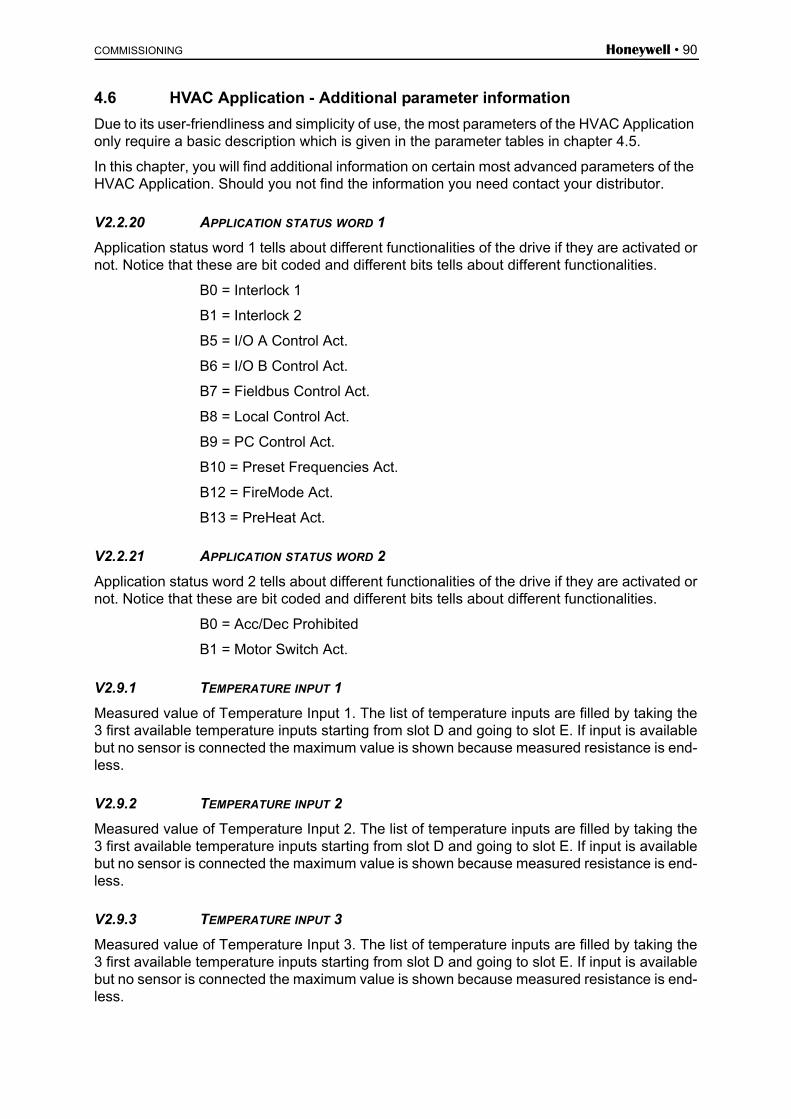
COMMISSIONING Honeywell • 90
4.6 HVAC Application - Additional parameter information
Due to its user-friendliness and simplicity of use, the most parameters of the HVAC Application only require a basic description which is given in the parameter tables in chapter 4.5.
In this chapter, you will find additional information on certain most advanced parameters of the HVAC Application. Should you not find the information you need contact your distributor.
V2.2.20 APPLICATION STATUS WORD 1
Application status word 1 tells about different functionalities of the drive if they are activated ornot. Notice that these are bit coded and different bits tells about different functionalities.
B0 = Interlock 1
B1 = Interlock 2
B5 = I/O A Control Act.
B6 = I/O B Control Act.
B7 = Fieldbus Control Act.
B8 = Local Control Act.
B9 = PC Control Act.
B10 = Preset Frequencies Act.
B12 = FireMode Act.
B13 = PreHeat Act.
V2.2.21 APPLICATION STATUS WORD 2
Application status word 2 tells about different functionalities of the drive if they are activated ornot. Notice that these are bit coded and different bits tells about different functionalities.
B0 = Acc/Dec Prohibited
B1 = Motor Switch Act.
V2.9.1 TEMPERATURE INPUT 1
Measured value of Temperature Input 1. The list of temperature inputs are filled by taking the3 first available temperature inputs starting from slot D and going to slot E. If input is availablebut no sensor is connected the maximum value is shown because measured resistance is end-less.
V2.9.2 TEMPERATURE INPUT 2
Measured value of Temperature Input 2. The list of temperature inputs are filled by taking the3 first available temperature inputs starting from slot D and going to slot E. If input is availablebut no sensor is connected the maximum value is shown because measured resistance is end-less.
V2.9.3 TEMPERATURE INPUT 3
Measured value of Temperature Input 3. The list of temperature inputs are filled by taking the3 first available temperature inputs starting from slot D and going to slot E. If input is availablebut no sensor is connected the maximum value is shown because measured resistance is end-less.

Honeywell • 91 COMMISSIONING
P3.1.1.7 MOTOR CURRENT LIMIT
This parameter (Motor current limit) determines the maximum motor current from the drive. Theparameter value range differs from size to size.
When the current limit is active the drive output frequency is decreased.
NOTE: This is not an overcurrent trip limit.
P3.1.1.8 MOTOR TYPE
This parameter defines the used motor type.
P3.1.2.7 U/F RATIO SELECTION
Figure 17.Linear and squared change of motor voltage
Selection number
Selection name Description
0 Induction motor (IM) Select if an induction motor is used.
1 Permanent Magnet Motor (PM) Select if a permanent magnet motor is used.
Selection number
Selection name Description
0 Linear The voltage of the motor changes linearly as a function of output frequency from zero frequency voltage (P3.1.2.3) to the field weakening point (FWP) voltage at FWP frequency. This default setting should be used if there is no special need for another setting.
1 Squared The voltage of the motor changes from zero point voltage (P3.1.2.3) following a squared curve form from zero to the field weakening point. The motor runs undermagnetised below the field weakeningpoint and produces less torque. Squared U/f ratio can be used in applications where torque demand is proportional to the square of the speed, e.g. in centrifugal fans and pumps.
U[V]
f[Hz]
100K07
Default: Nominalvoltage of the motor
Linear
Squared
Fieldweakeningpoint
Default:Nominal frequencyof the motor

COMMISSIONING Honeywell • 92
t
Outputfrequency
FWD
REV
Ctrl signal 2
Ctrl signal 1
Run enable
Set frequency
Set frequen cy
0 Hz
Keypad stopbutton
Keypad startbutton
1 2 3 4 5 6 7 8 9 10 11 12 13
100K29
P3.1.2.8 OVERVOLTAGE CONTROLLER
P3.1.2.9 UNDERVOLTAGE CONTROLLER
These parameters allow the under-/overvoltage controllers to be switched out of operation.This may be useful, for example, if the mains supply voltage varies more than -15% to +10%and the application will not tolerate this over-/undervoltage.
P3.1.2.10 ENERGY OPTIMIZATION
The drive searches for the minimum motor current in order to save energy and to lower the mo-tor noise. This function can be used e.g. in fan and pump applications.
0 = Disabled
1 = Enabled
P3.1.2.11 FLYING START OPTIONS
When the selection Both directions is chosen, the shaft frequency is searched from both thepositive and negative directions. By selection FreqRef direction, the search is limited to the fre-quency reference direction only to avoid any shaft movement for the other direction.
0 = Both directions
1 = FreqRef direction
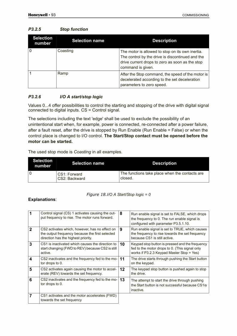
Honeywell • 93 COMMISSIONING
P3.2.5 Stop function
P3.2.6 I/O A start/stop logic
Values 0...4 offer possibilities to control the starting and stopping of the drive with digital signalconnected to digital inputs. CS = Control signal.
The selections including the text 'edge' shall be used to exclude the possibility of an unintentional start when, for example, power is connected, re-connected after a power failure, after a fault reset, after the drive is stopped by Run Enable (Run Enable = False) or when the control place is changed to I/O control. The Start/Stop contact must be opened before the motor can be started.
The used stop mode is Coasting in all examples.
Figure 18.I/O A Start/Stop logic = 0Explanations:
Selection number
Selection name Description
0 Coasting The motor is allowed to stop on its own inertia. The control by the drive is discontinued and the drive current drops to zero as soon as the stop command is given.
1 Ramp After the Stop command, the speed of the motor is decelerated according to the set deceleration parameters to zero speed.
Selection number
Selection name Description
0 CS1: ForwardCS2: Backward
The functions take place when the contacts are closed.
1 Control signal (CS) 1 activates causing the out- put frequency to rise. The motor runs forward.
8 Run enable signal is set to FALSE, which dropsthe frequency to 0. The run enable signal is configured with parameter P3.5.1.10.
2 CS2 activates which, however, has no effect on the output frequency because the first selected direction has the highest priority.
9 Run enable signal is set to TRUE, which causes the frequency to rise towards the set frequency because CS1 is still active.
3 CS1 is inactivated which causes the direction to start changing (FWD to REV) because CS2 is still active.
10 Keypad stop button is pressed and the frequency fed to the motor drops to 0. (This signal only works if P3.2.3 Keypad Master Stop = Yes)
4 CS2 inactivates and the frequency fed to the mo-tor drops to 0.
11 The drive starts through pushing the Start button on the keypad.
5 CS2 activates again causing the motor to accel-erate (REV) towards the set frequency.
12 The keypad stop button is pushed again to stop the drive.
6 CS2 inactivates and the frequency fed to the mo-tor drops to 0.
13 The attempt to start the drive through pushing the Start button is not successful because CS1is inactive.
7 CS1 activates and the motor accelerates (FWD) towards the set frequency

COMMISSIONING Honeywell • 94
Figure 19.I/O A Start/Stop logic = 1Explanations:
Selection number
Selection name Description
1 CS1: Forward (edge)CS2: Inverted stop
1 Control signal (CS) 1 activates causing the output frequency to rise. The motor runs forward.
6 CS1 activates and the motor accelerates (FWD) towards the set frequency because the Run enable signal has been set to TRUE.
2 CS2 inactivates causing the frequency to drop to 0.
7 Keypad stop button is pressed and the frequency fed to the motor drops to 0. (This signal only works if P3.2.3 Keypad Master Stop = Yes)
3 CS1 activates causing the output frequency to rise again. The motor runs forward.
8 CS1 activates causing the output frequency to rise again. The motor runs forward.
4 Run enable signal is set to FALSE, which drops the frequency to 0. The run enable signal is con-figured with parameter P3.5.1.10.
9 CS2 inactivates causing the frequency to drop to 0.
5 Start attempt with CS1 is not successful because Run enable signal is still FALSE.
t
Outputfrequency
FWD
REV
Ctrl signal 2
Ctrl signal 1
Run enable
Set frequency
Set frequency
0Hz
Keypad stopbutton
100K30
71 2 3 4 5 6 98

Honeywell • 95 COMMISSIONING
Figure 20.I/O A Start/Stop logic = 2Explanations:
Selection number
Selection name Description
2 CS1: Forward (edge)CS2: Backward (edge)
Shall be used to exclude the possibility of an unintentional start. The Start/Stop contact must be opened before the motor can be restarted.
1 Control signal (CS) 1 activates causing the output frequency to rise. The motor runs forward.
7 CS1 activates and the motor accelerates (FWD)towards the set frequency
2 CS2 activates which, however, has no effect onthe output frequency because the first selected direction has the highest priority.
8 Run enable signal is set to FALSE, which dropsthe frequency to 0. The run enable signal is con-figured with parameter P3.5.1.10.
3 CS1 is inactivated which causes the direction to start changing (FWD to REV) because CS2 isstill active.
9 Run enable signal is set to TRUE, which, unlike if value 0 is selected for this parameter, has noeffect because rising edge is required to start even if CS1 is active.
4 CS2 inactivates and the frequency fed to the mo-tor drops to 0.
10 Keypad stop button is pressed and the frequency fed to the motor drops to 0. (This signal only works if P3.2.3 Keypad Master Stop = Yes).
5 CS2 activates again causing the motor to accel-erate (REV) towards the set frequency
11 CS1 is opened and closed again which causes the motor to start.
6 CS2 inactivates and the frequency fed to the mo-tor drops to 0.
12 CS1 inactivates and the frequency fed to the motor drops to 0.
t
Outputfrequency
FWD
REV
Ctrl signal 2
Ctrl signal 1
Run enable
Set frequency
Set frequency
0 Hz
Keypad stopbutton
1 2 3 4 5 6 7 8 9 10 11 12
100K31

COMMISSIONING Honeywell • 96
Figure 21.I/O A Start/Stop logic = 3
Explanations:
Selection number
Selection name Description
3 CS1: StartCS2: Reverse
1 Control signal (CS) 1 activates causing the output frequency to rise. The motor runs forward.
7 Run enable signal is set to FALSE, which drops the frequency to 0. The run enable signal is configured with parameter P3.5.1.10.
2 CS2 activates which causes the direction to start changing (FWD to REV).
8 Run enable signal is set to TRUE, which causes the frequency to rise towards the set frequency because CS1 is still active.
3 CS2 is inactivated which causes the direction to start changing (REV to FWD) because CS1 is still active.
9 Keypad stop button is pressed and the frequency fed to the motor drops to 0. (This signal only works if P3.2.3 Keypad Master Stop = Yes)
4 Also CS1 inactivates and the frequency drops to 0.
10 The drive starts through pushing the Start button on the keypad.
5 Despite the activation of CS2, the motor doesnot start because CS1 is inactive.
11 The drive is stopped again with the stop buttonon the keypad.
6 CS1 activates causing the output frequency torise again. The motor runs forward because CS2is inactive.
12 The attempt to start the drive through pushingthe Start button is not successful because CS1is inactive.
t
Outputfrequency
FWD
REV
Ctrl signal 2
Ctrl signal 1
Run enable
Set frequency
Set frequency
0 Hz
Keypad stopbutton
Keypad startbutton
1 2 3 4 6 7 8 9 10 11 12
100K325

Honeywell • 97 COMMISSIONING
Figure 22.I/O A Start/Stop logic = 4Explanations:
Selection number
Selection name Description
4 CS1: Start (edge)CS2: Reverse
Shall be used to exclude the possibility of an unintentional start.The Start/Stop contact must be opened before the motor can be restarted.
1 Control signal (CS) 1 activates causing the output frequency to rise. The motor runs forward because CS2 is inactive.
7 Run enable signal is set to FALSE, which drops the frequency to 0. The run enable signal is configured with parameter P3.5.1.10.
2 CS2 activates which causes the direction to start changing (FWD to REV).
8 Before a successful start can take place, CS1 must be opened and closed again.
3 CS2 is inactivated which causes the direction to start changing (REV to FWD) because CS1 is still active.
9 Keypad stop button is pressed and the frequency fed to the motor drops to 0. (This signal only works if P3.2.3 Keypad Master Stop = Yes)
4 Also CS1 inactivates and the frequency drops to 0.
10 Before a successful start can take place, CS1 must be opened and closed again.
5 Despite the activation of CS2, the motor does not start because CS1 is inactive.
11 CS1 inactivates and the frequency drops to 0.
6 CS1 activates causing the output frequency to rise again. The motor runs forward because CS2 is inactive.
t
Outputfrequency
FWD
REV
Ctrl signal 2
Ctrl signal 1
Run enable
Set frequency
Set frequency
0Hz
Keypad stopbutton
1 2 3 4
5
6 7 8 9 10
100K33
11

COMMISSIONING Honeywell • 98
Figure 23. AI1 threshold
P3.2.3 KEYPAD MASTER STOP
The drive can be forced to stop state from keypad stop button even if it is controlled from an-other control place (Remote). If this measure is taken, the drive goes to the alarm state andcannot be restarted from the remote control place before the start button has been pressed(while in Remote).
You can still momentarily switch to Local and start there but when going back to Remote a startbutton press is needed. This also applies after a power-down as the state of this function is re-tained in memory.
The function can be enabled or disabled with this parameter.
P3.3.10 PRESET FREQUENCY MODE
You can use the preset frequency parameters to define certain frequency references in ad-vance. These references are then applied by activating/inactivating digital inputs connected toparameters P3.5.1.16, P3.5.1.17 and P3.5.1.18 ((Preset frequency selection 0, Preset frequen-cy selection 1 and Preset frequency selection 2). Two different logics can be selected:
Selection number
Selection name Description
5 CS1: Not needed (AI1level will start the device)CS2: Reverse
Special start mode where no separate start signal is needed. Increasing the value of AI1 will act as a start command. AI1 threshold ( P3.2.8) described in Figure 24 will create a safety margin to prevent unintentional starts. So the drive will start after the value of AI1 exceeds the threshold.Control signal 2 can be used for changing the rotation direction.
0% 100% 9179.emf
Startcommand
1 = Active
0 = Not active
AI1 threshold -2%AI1 threshold
AI1

Honeywell • 99 COMMISSIONING
P3.3.11 TO
P3.3.18 PRESET FREQUENCIES 1 TO 7
The values of the preset frequencies are automatically limited between the minimum and max-imum frequencies (P3.3.1 and P3.3.2). See table below.
Table 72. Selection of preset frequencies (B0 = Preset frequency selection 0, B1 = Preset frequency selection 1, B2 = Preset frequency selection 2); = input activated
EXAMPLE
If you want to activate Preset frequency 3, inputs B0 and B1 must be activated. B0 and B1 are by default set to DigIN SlotA.4 and DigIN SlotA.5 respectively. They can be changed by chang-ing the parameters Preset Freq Sel0 (P3.5.1.16) and Preset Freq Sel1 (P3.5.1.17) under Parameters > I/O Config > Digital inputs. By default, Preset frequency 3 is set to 20.00Hz. You can set it to a different value by changing the parameter Preset Freq 3 (P3.3.14) under Parameters > References.
P3.4.1 RAMP 1 SHAPE
The start and end of acceleration and deceleration ramps can be smoothed with this parame-ter. Setting value 0 gives a linear ramp shape which causes acceleration and deceleration toact immediately to the changes in the reference signal.
Setting value 0.1…10 seconds for this parameter produces an S-shaped acceleration/deceler-ation. The acceleration time is determined with parameters P3.4.2 and P3.4.3. See Figure 24.
These parameters are used to reduce mechanical erosion and current spikes when the refer-ence is changed.
Selection number Selection name Note
0 Binary coded Combine activated inputs according to Table 72 to choose the Preset frequency needed.
1 Number (of inputs used) According to how many of the inputs assigned for Preset fre-quency selections are active you can apply the Preset fre-quencies 1 to 3.
Required action Activated frequency
Choose value 1 for parame-ter P3.3.3
Preset frequency 0
B2 B1 B0 Preset frequency 1
B2 B1 B0 Preset frequency 2
B2 B1 B0 Preset frequency 3
B2 B1 B0 Preset frequency 4
B2 B1 B0 Preset frequency 5
B2 B1 B0 Preset frequency 6
B2 B1 B0 Preset frequency 7

COMMISSIONING Honeywell • 100
Figure 24. Acceleration/Deceleration (S-shaped)
P3.4.2 ACCELERATION TIME 1
Acceleration Time 1 defines the time it takes for the output frequency to accelerate from zeroto Maximum Frequency.
P3.4.3 DECELERATION TIME 1
Deceleration Time 1 defines the time it takes for the output frequency to decelerate from Max-imum Frequency to zero.
P3.4.6 ACCELERATION TIME 2
Second ramp which can be activated with a digital input or frequency threshold. Functionalitysame as Accel Time 1.
P3.4.7 DECELERATION TIME 2
Second ramp which can be activated with a digital input or frequency threshold. Functionalitysame as Decel Time 1.
P3.4.8 RAMP TIME OPTIMIZER
If the ramp time optimizer is enabled the deceleration time will be increased by the percentagedefined in parameter P3.4.9 Ramp optimizing percentage every time we hit the overvoltagecontroller during deceleration, or acceleration time when hitting the current limit during accel-eration. There is also a parameter for setting a max limit for the ramp (P3.4.10). The ramp op-timizer will not stretch the ramps above this limit.
NOTE: The ramp time optimizer only affects the settings of Ramp 1. Ramp 2 will not be modi-fied.
P3.4.2, P3.4.3
[Hz]
[t]
P3.4.1
P3.4.1
11096.emf

Honeywell • 101 COMMISSIONING
Figure 25.
P3.4.16 FLUX BRAKING
Instead of DC braking, flux braking is a useful way to raise the braking capacity in cases whereadditional brake resistors are not needed.
When braking is needed, the frequency is reduced and the flux in the motor is increased, whichin turn increases the motor's capability to brake. Unlike DC braking, the motor speed remainscontrolled during braking.
The flux braking can be set ON or OFF.
NOTE: Flux braking converts the energy into heat at the motor, and should be used intermit-tently to avoid motor damage.
P3.5.1.10 RUN ENABLE
Contact open: Start of motor disabled
Contact closed: Start of motor enabled
The drive is stopped according to the selected function at P3.2.5. The follower drive will alwayscoast to stop.
P3.5.1.11 RUN INTERLOCK 1P3.5.1.12 RUN INTERLOCK 2
The drive cannot be started if any of the interlocks are open.
The function could be used for a damper interlock, preventing the drive to start with damperclosed.
Output frequency
Maximumfrequency
Old decelerationtime
New deceleration time(Old optimizing percentage)
Time7072.emf

COMMISSIONING Honeywell • 102
P3.5.1.16 PRESET SPEED B0P3.5.1.17 PRESET SPEED B1P3.5.1.18 PRESET SPEED B2
Connect a digital input to these functions with the programming method presented in chapter4.5.2) to be able to apply Preset frequencies 1 to 7 (see Table 72 and pages 58, 61 and 99).
P3.5.1.30 INTERLOCK 5
Digital input signal used for motor/pump interlock with Multi-Pump system if Interlocks are en-abled in the Multi-Pump menu. If enabled, a closed input tells the system that the motor/pumpis available.
P3.5.1.38 FIRE MODE PRESET FREQ SEL 0P3.5.1.39 FIRE MODE PRESET FREQ SEL 1
Activation for Fire Mode preset frequencies. These two parameters are connected to P3.17.7,P3.17.8 and P3.17.9. By closing and opening contacts different preset frequencies can beused.
P3.5.2.2 AI1 SIGNAL FILTER TIME
When this parameter is given a value greater than 0 the function that filters out disturbancesfrom the incoming analog signal is activated.
NOTE: Long filtering time makes the regulation response slower!
Figure 26. AI1 signal filtering
Fire Mode preset sel 0 Fire Mode preset sel 1 Preset frequency in use
Open contact Open contact None
Closed contact Open contact Preset frequency 1
Open contact Closed contact Preset frequency 2
Closed contact Closed contact Preset frequency 3
%
100%
63%
P3.5.2.2
t [s]
11097.emf
Filtered signal
Unfiltered signal

Honeywell • 103 COMMISSIONING
M3.5.3.2.1 BASIC RO1 FUNCTION
Selection Selection name Description
0 None Output not used
1 Ready The AC drive is ready to operate
2 Run The AC drive operates (motor is running)
3 Fault A fault trip has occurred
4 Fault invert A fault trip has not occurred
5 Alarm An alarm has been initiated
6 Reverse The reverse command has been given
7 At speed The output frequency has reached the set reference
8 MotorRegAct One of the limit regulators (e.g. current limit, torque limit) is activated
9 Preset Speed The preset frequency has been selected with digital input
10 Keypad CTRL Keypad control selected (active control place is keypad)
11 I/O B CTRL I/O control place B selected (active control place is I/O B)
12 LimSuperv1 Activates if the signal value falls below or exceeds the set supervision limit (P3.8.3 or P3.8.7) depending on the selected function.
13 LimSuperv2
14 Start Signal Drive start command is active.
15 Reserved
16 Fire Mode Activation FireMode function is active
17 RTC T1 CTRL Status of Time channel 1
18 RTC T2 CTRL Status of Time channel 2
19 RTC T3 CTRL Status of Time channel 3
20 Fieldbus CW.B13 Digital (relay) output control from Fieldbus control word bit 13.
21 Fieldbus CW.B14 Digital (relay) output control from Fieldbus control word bit 14.
22 Fieldbus CW.B15 Digital (relay) output control from Fieldbus control word bit 15.
23 PID1 Sleep PID-controller is in Sleep mode.
24 Reserved -
25 PID1 Supervision PID-controller value is beyond the supervision limits.
26 PID2 Supervision PID-controller value is beyond the supervision limits.
27 Motor 1 Control Contactor control for Multi-pump function
28 Motor 2 Control Contactor control for Multi-pump function
29 Motor 3 Control Contactor control for Multi-pump function
30 Motor 4 Control Contactor control for Multi-pump function
31 Motor 5 Control Contactor control for Multi-pump function
32 Reserved -
33 Reserved -
34 MaintenAlarm Maintenance counter has reached the alarm limit
35 MaintenFault Maintenance counter has reached the fault limit

COMMISSIONING Honeywell • 104
Table 73. Output signals via RO1
P3.7.9 RESONANCE SWEEP
The anti-resonance function slowly sweeps through frequencies from MinFreq to MaxFreq andback to MinFreq with the ramp times set with this parameter. During this sweep, the user shouldpress the OK-button every time passing a resonance range in order to tag where the rangestarts and ends.
If everything is fine the Prohibit frequency range parameters (in Prohibited Frequencies menu)are provided with right information. If there is a different amount of tags during ramp-up com-pared to ramp-down nothing will be done but an info message is shown. The same will happenif the bands are not reasonable.
Figure 27.
P3.9.1 AI LOW FAULT
This parameter defines the response for F50 - AI Low Fault (Fault ID: 1050).
NOTE: AI Low Fault response 3 (Alarm + Previous Freq) can be used only if analog input 1 oranalog input 2 is used as frequency reference.
36 Thermistor Fault A thermistor fault has occurred.
37 Motor Switch Open motor switch has been detected.
Selection number
Selection name Description
0 No action No action
1 Alarm Trigs Alarm
2 Alarm, preset freq Uses preset frequencies as frequency reference
3 Alarm, previous freq The last valid frequency is kept as frequency reference
4 Fault Stop according to Stop mode P3.2.5
5 Fault, coast Stop by coasting
Selection Selection name Description
9178
.em
f
Min freq Max freq
Tagged withOK button Successful!
Min freq Max freq
Failed!

Honeywell • 105 COMMISSIONING
M3.9.2 RESPONSE TO EXTERNAL FAULT
An alarm message or a fault action and message is generated by an external fault external faultsignal in one of the programmable digital inputs (DI3 by default) using parameters P3.5.1.7 andP3.5.1.8. The information can also be programmed into any of the relay outputs.
P3.9.8 MOTOR THERMAL ZERO SPEED COOLING
Defines the cooling factor at zero speed in relation to the point where the motor is running atnominal speed without external cooling.
The default value is set assuming that there is no external fan cooling the motor. If an externalfan is used this parameter can be set to 90% (or even higher).
If you change the parameter P3.1.1.4 (Motor nominal current), this parameter is automaticallyrestored to the default value.
Setting this parameter does not affect the maximum output current of the drive which is deter-mined by parameter P3.1.1.7 alone.
The corner frequency for the thermal protection is 70% of the motor nominal frequency(P3.1.1.2).
Figure 28. Motor thermal current IT curve
P3.9.9 MOTOR THERMAL TIME CONSTANT
This is the thermal time constant of the motor. The bigger the motor, the bigger the time con-stant. The time constant is the time within which the calculated thermal stage has reached 63%of its final value.
The motor thermal time is specific to the motor design and it varies between different motormanufacturers. The default value of the parameter varies from size to size.
If the motor's t6-time (t6 is the time in seconds the motor can safely operate at six times therated current) is known (given by the motor manufacturer) the time constant parameter can beset basing on it. As a rule of thumb, the motor thermal time constant in minutes equals to 2*t6.If the drive is in stop stage the time constant is internally increased to three times the set pa-
ffn
Par.P3.9.8=40%
0
11098.emf
IT100%Overload area
Pcooling
Corner freq

COMMISSIONING Honeywell • 106
rameter value. The cooling in stop stage is based on convection and the time constant is in-creased. See Figure 29.
P3.9.10 MOTOR THERMAL LOADIBILITY FACTOR
Setting value to 130% means that the nominal temperature will be reached with 130% of motornominal current.
Figure 29. Motor temperature calculation
P3.9.12 STALL CURRENT
The current can be set to 0.0…2*IL. For a stall stage to occur, the current must have exceeded this limit. See Figure 31. If parameter P3.1.1.7 Motor current limit is changed, this parameteris automatically calculated to 90% of the current limit. See Group 3.9: Protections.
NOTE! In order to guarantee desired operation, this limit must be set below the current limit.
105%
Q = (I/IT)2 x (1-e-t/T)
I/IT
11099.emf
Trip area
Motor temperature
TimeMotor temperature
Time constant T*)
*) Changes by motor size and adjusted with P3.9.9
Fault/alarmP3.9.6
Motor•current

Honeywell • 107 COMMISSIONING
Figure 30.Stall characteristics settings
P3.9.13 STALL TIME LIMIT
This time can be set between 1.0 and 120.0s.
This is the maximum time allowed for a stall stage. The stall time is counted by an internal up/down counter.
If the stall time counter value goes above this limit the protection will cause a trip (see P3.9.11). See Group 3.9: Protections.
Figure 31.Stall time count
f
I
Par. P3.9.12
Par. P3.9.14
100K34.fh11
Stall area
Par. P3.9.13
100K36.fh11
Trip area
Time
Stall time counter
StallNo stall
Trip/warningpar. P3.9.11

COMMISSIONING Honeywell • 108
P3.9.16 UNDERLOAD PROTECTION: FIELD WEAKENING AREA LOAD
The torque limit can be set between 10.0-150.0 % x TnMotor..
This parameter gives the value for the minimum torque allowed when the output frequency isabove the field weakening point. See Figure 31.
If you change parameter P3.1.1.4 (Motor nominal current) this parameter is automatically re-stored to the default value. See Group 3.9: Protections.
Figure 32.Setting of minimum load
P3.9.18 UNDERLOAD PROTECTION: TIME LIMIT
This time can be set between 2.0 and 600.0 s.
This is the maximum time allowed for an underload state to exist. An internal up/down countercounts the accumulated underload time. If the underload counter value goes above this limitthe protection will cause a trip according to parameter P3.9.15). If the drive is stopped the underload counter is reset to zero. See Figure 32 and Group 3.9: Protections.
Par.P3.9.16
100K36
Par.P3.9.17
f5 Hz
Underload area
Torque
Fieldweakeningpoint

Honeywell • 109 COMMISSIONING
Figure 33.Underload time counter function
P3.9.25 TEMPERATURE FAULT SIGNAL
This parameter allows you to select the temperature inputs to be used for temperature fault.
0 = Not Used
1 = TempInput 1
2 = TempInput 2
3 = TempInput 3
4 = TempInput 1-2
5 = TempInput 2-3
6 = TempInput 1-3
P3.9.26 TEMPERATURE ALARM LIMIT
Temperature for trigging an alarm.
P3.9.27 TEMPERATURE FAULT LIMIT
Temperature for trigging a fault.
P3.9.28 TEMPERATURE FAULT RESPONSE
Determines the response if limit of P3.9.26 or P3.9.27 is reached.
0 = No action
1 = Alarm
2 = Fault
3 = Fault, coast
M3.10.1 AUTOMATIC RESET
Activate the Automatic reset after fault with this parameter.
Par. P3.9.18
100K37
Trip area
Time
Underload time counter
UnderloadNo underl.
Trip/warningpar. P3.9.15

COMMISSIONING Honeywell • 110
NOTE: Automatic reset is allowed for certain faults only. By giving the parameters P3.10.6 toP3.10.13 the value 0 or 1 you can either allow or deny the automatic reset after the respectivefaults.
P3.10.3 WAIT TIME
P3.10.4 AUTOMATIC RESET: TRIAL TIME
P3.10.5 NUMBER OF TRIALS
The Automatic reset function keeps resetting the faults appearing during the time set with thisparameter. If the number of faults during the trial time exceed the value of parameter P3.10.5a permanent fault is generated. Otherwise the fault is cleared after the trial time has elapsedand the next fault start the trial time count again.
Parameter P3.10.5 determines the maximum number of automatic fault reset attempts during the trial time set by this parameter. The time count starts from the first autoreset. The maximum number is independent of the fault type.
Figure 34. Automatic reset function
11104.emf
Fault trigger
Autoreset
Trial time
Wait timeP3.10.3
Reset 1 Reset 2
Trial timeP3.10.4
Fault active
Alarm
Number of trials: (P3.10.5 = 2)
Wait timeP3.10.3
Wait timeP3.10.3

Honeywell • 111 COMMISSIONING
P3.13.1.4 PROCESS UNIT SELECTION
P3.14.1.6 PROCESS UNIT SELECTION
Table 74. Process units
Process Units Process Units
% °C
1/min GPM
rpm gal/s
ppm gal/min
pps gal/h
l/s lb/s
l/min lb/min
l/h lb/h
kg/s CFM
kg/min ft3/s
kg/h ft3/min
m3/s ft3/h
m3/min ft/s
m3/h in wg
m/s ft wg
mbar PSI
bar lb/in2
Pa hp
kPa F
mVS

COMMISSIONING Honeywell • 112
P3.13.1.9 DEAD BAND HYSTERESIS
P3.13.1.10 DEAD BAND DELAY
The PID controller output is locked if the actual value stays within the deadband area aroundthe reference for a predefined time. This function will prevent unnecessary movement and wearon actuators, e.g. valves.
Figure 35. Dead band
11105.emf
Dead band (P3.12.1.9) Reference
Dead band delay (P3.12.1.10)
Output locked
Actual value

Honeywell • 113 COMMISSIONING
P3.13.2.7 SLEEP FREQUENCY LIMIT 1P3.13.2.8 SLEEP DELAY 1P3.13.2.9 WAKE-UP LEVEL 1
This function will put the drive into sleep mode if the frequency stays below the sleep limit fora longer time than that set with the Sleep Delay (P3.13.2.8). This means that the start com-mand remains on, but the run request is turned off. When the actual value goes below, orabove, the wake-up level depending on the set acting mode the drive will activate the run re-quest again if the start command is still on.
Figure 36. Sleep limit, Sleep delay, Wake-up level
P3.13.4.1 FEEDFORWARD FUNCTION
Feedforward usually needs accurate process models, but in some simple cases a gain + offset type of feedforward is enough. The feedforward part does not use any feedback measurements of the actual controlled process value (water level in the example on page 114). The feedfor-ward control uses other measurements which are indirectly affecting the controlled process val-ue.
Example 1:
Controlling the water level of a tank by means of flow control. The desired water level has beendefined as a setpoint and the actual level as feedback. The control signal acts on the incomingflow.
The outflow could be thought of as a disturbance that can be measured. Based on the mea-surements of the disturbance, we can try to compensate for this disturbance by simple feedfor-ward control (gain and offset) which is added to the PID output.
This way the controller would react much faster to changes in the outflow than if you just hadmeasured the level.
11106.emf
Actual value
Wake-up level(P3.12.2.9)
Frequency
Sleep limit(P3.12.2.7)
Sleep delay
(P3.12.2.8)
SleepRegulating mode Regulating mode

COMMISSIONING Honeywell • 114
Figure 37. Feedforward control
M3.13.5.1 ENABLE PROCESS SUPERVISION
Figure 38. Process supervision
Upper and lower limits around the reference are set. When the actual value goes above or be-low these a counter starts counting up towards the Delay (P3.13.5.4). When the actual valueis within the allowed area the same counter counts down instead. Whenever the counter ishigher than the Delay an alarm or fault (depending on the selected response) is generated.
PID+ +
LT FT
11107.emf
FFWLevel ref
Level control
Outflowcontrol
11108.emf
Regulating mode
Upper limit
P3.12.5.2)
Lower limit
(P3.12.5.3)
Actual value
Delay (P3.12.5.4)
Alarm or fault
Reference

Honeywell • 115 COMMISSIONING
PRESSURE LOSS COMPENSATION
Figure 39. Position of pressure sensor
If pressurizing a long pipe with many outlets, the best place for the sensor would probably be halfway down the pipe (Position 2). However, sensors might, for example, be placed directly after the pump. This will give the right pressure directly after the pump, but farther down in the pipe the pressure will drop depending on the flow.
11109.emf
PTPT
Pressure
No flow
With flow
Pipe length
Position 1 Position 2

COMMISSIONING Honeywell • 116
P3.13.6.1 ENABLE SETPOINT 1P3.13.6.2 SETPOINT 1 MAX COMPENSATION
The sensor is placed in Position 1. The pressure in the pipe will remain constant when we haveno flow. However, with flow, the pressure will drop farther down in the pipe. This can be com-pensated by raising the setpoint as the flow increases. In this case, the flow is estimated by theoutput frequency and the setpoint is linearly increased with the flow as in the figure below.
Figure 40. Enable setpoint 1 for pressure loss compensation
11110.emf
PTPT
Position 1 Position 2
Pressure
No flowWith flow and compensation
Pipe length
Setpoint
Max Freq and FlowMin Freq and Flow
Setpoint + Max compensation
Setpoint
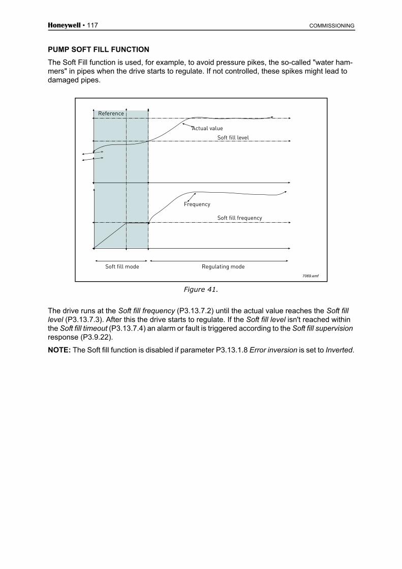
Honeywell • 117 COMMISSIONING
PUMP SOFT FILL FUNCTION
The Soft Fill function is used, for example, to avoid pressure pikes, the so-called "water ham-mers" in pipes when the drive starts to regulate. If not controlled, these spikes might lead to damaged pipes.
Figure 41.
The drive runs at the Soft fill frequency (P3.13.7.2) until the actual value reaches the Soft fill level (P3.13.7.3). After this the drive starts to regulate. If the Soft fill level isn't reached within the Soft fill timeout (P3.13.7.4) an alarm or fault is triggered according to the Soft fill supervision response (P3.9.22).
NOTE: The Soft fill function is disabled if parameter P3.13.1.8 Error inversion is set to Inverted.
7069.emf
Reference
Soft fill level
Actual value
Soft fill mode Regulating mode
Frequency
Soft fill frequency

COMMISSIONING Honeywell • 118
Use of Pump and Fan Cascade
A motor/motors are connected/disconnected if the PID controller is not able to keep the processvalue or feedback within the defined bandwith around the setpoint.
Criteria for connecting/adding motors (also see Figure 42):
• Feedback value outside the bandwidth area.• Regulating motor running at a “close-to-max” frequency (-2Hz)• Conditions above are fulfilled for a time longer than the bandwidth delay• There are more motors available
Figure 42.
Criteria for disconnecting/removing motors:
• Feedback value outside bandwidth area.• Regulating motor running at a “close-to-min” frequency (+2 Hz)• Conditions above are fulfilled for a time longer than the bandwidth delay• There are more motors running than the regulating one.
P3.15.2 INTERLOCK FUNCTION
Interlocks can be used to tell the Multi Pump system that a motor is not available e.g. becauseof the motor is removed from the system for maintenance or bypassed for manual control.
Enable this function to use the interlocks. Choose the needed status for each motor by digitalinputs (parameters P3.5.1.26 to P3.5.1.29). If the input is closed (TRUE) the motor is availablefor the Multi Pump system, otherwise it will not be connected by the Multi Pump logic.
ONOFFONOFF
11111.emf
Motor 2
Motor 3
Delay
Bandwidth
Feedback
Setpoint
Drive is running at maximumor close to maximum frequency

Honeywell • 119 COMMISSIONING
EXAMPLE OF THE INTERLOCK LOGIC:
If the motor starting order is
1->2->3->4->5
Now, the interlock of motor 3 is removed, i.e. the value of parameter P3.5.1.27 is set to FALSE,the order changes to:
1->2->4->5.
If motor 3 is taken into use again (changing the value of parameter P3.5.1.27 to TRUE) the sys-tem runs on without stopping and motor 3 is placed last in the sequence:
1->2->4->5->3
As soon as the system is stopped or goes to sleep mode for the next time, the sequence isupdated to its original order.
1->2->3->4->5
P3.15.3 INCLUDE FC
WIRING
There are two different ways to make the connections depending on whether selection 0 or 1 isset as parameter value.
Selection 0, Disabled:
The drive or the regulating motor is not included in the autochange or interlocks logic. The driveis directly connected to motor 1 as in Figure 43 below. The other motors are auxiliary ones con-nected to the mains by contactors and controlled by relays in the drive.
Selection Selection name Description
0 Disabled Motor 1 (motor connected to drive) is always frequency controlled and not affected by interlocks.
1 Enabled All motors can be controlled and are affected by inter-locks.

COMMISSIONING Honeywell • 120
Figure 43.
Selection 1, Enabled:
If the regulating motor needs to be included in the autochange or interlock logic make the con-nection according to Figure 44 below.
Every motor is controlled with one relay but the contactor logic takes care that the first connect-ed motor is always connected to the drive and next to the mains.
M M M
K2 K3
K2 K3
9145.emf
Motor 1 Motor 2 Motor 3
Motor 1 control from relay Motor 2 control from relay Motor 3 control from relay
NOT USED
Mains
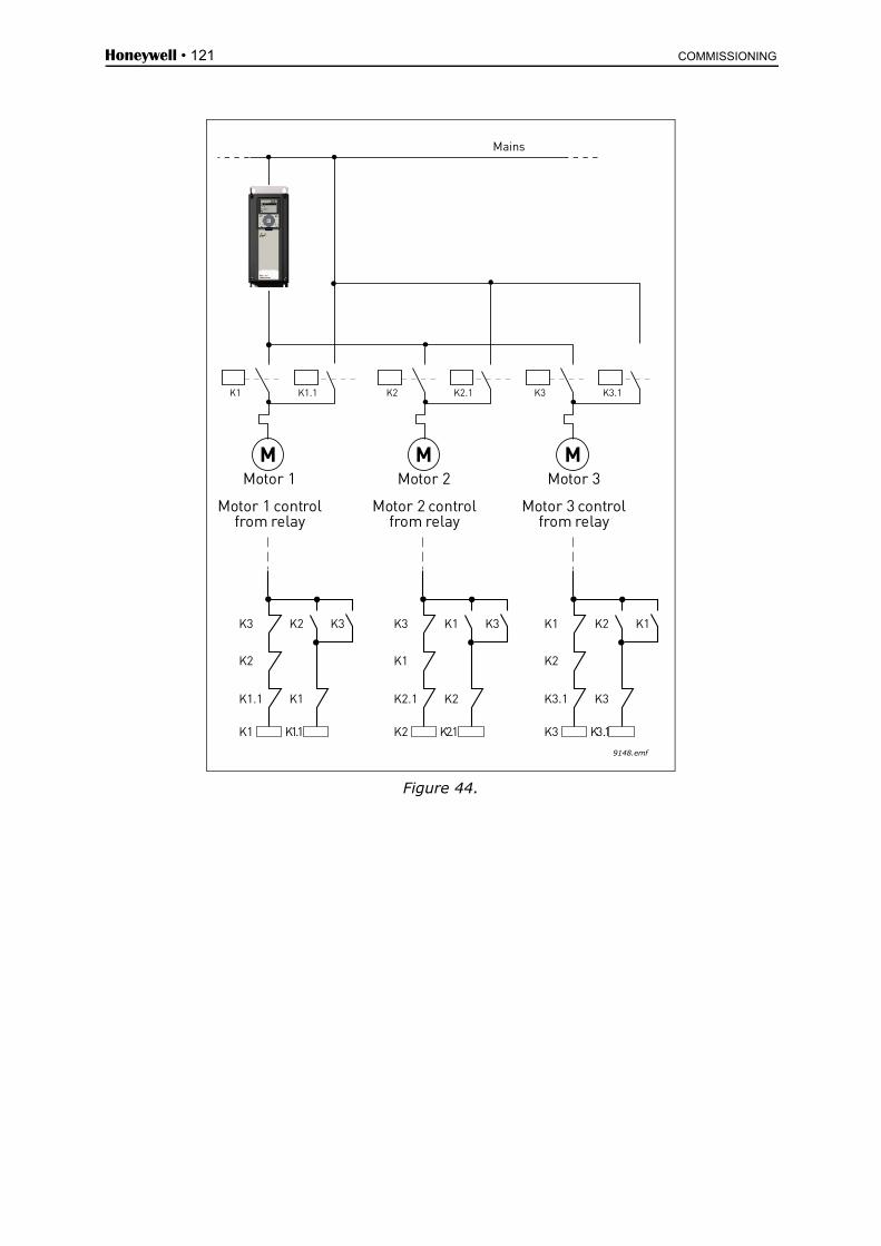
Honeywell • 121 COMMISSIONING
Figure 44.
M M M
K1 K1.1 K2 K2.1 K3 K3.1
9148.emf
K1 K1.1
K1.1 K1
K2
K3 K2 K3
K2 K2.1
K2.1 K2
K1
K3 K1 K3
K3 K3.1
K3.1 K3
K2
K1 K2 K1
Mains
Motor 1 Motor 2 Motor 3
Motor 1 controlfrom relay
Motor 2 controlfrom relay
Motor 3 controlfrom relay
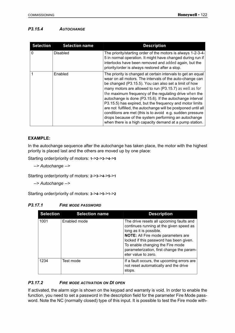
COMMISSIONING Honeywell • 122
P3.15.4 AUTOCHANGE
EXAMPLE:
In the autochange sequence after the autochange has taken place, the motor with the highestpriority is placed last and the others are moved up by one place:
Starting order/priority of motors: 1->2->3->4->5
--> Autochange -->
Starting order/priority of motors: 2->3->4->5->1
--> Autochange -->
Starting order/priority of motors: 3->4->5->1->2
P3.17.1 FIRE MODE PASSWORD
P3.17.2 FIRE MODE ACTIVATION ON DI OPEN
If activated, the alarm sign is shown on the keypad and warranty is void. In order to enable thefunction, you need to set a password in the description field for the parameter Fire Mode pass-word. Note the NC (normally closed) type of this input. It is possible to test the Fire mode with-
Selection Selection name Description
0 Disabled The priority/starting order of the motors is always 1-2-3-4-5 in normal operation. It might have changed during run if interlocks have been removed and added again, but the priority/order is always restored after a stop.
1 Enabled The priority is changed at certain intervals to get an equal wear on all motors. The intervals of the auto-change can be changed (P3.15.5). You can also set a limit of how many motors are allowed to run (P3.15.7) as well as for the maximum frequency of the regulating drive when the autochange is done (P3.15.6). If the autochange interval P3.15.5) has expired, but the frequency and motor limits are not fulfilled, the autochange will be postponed until all conditions are met (this is to avoid e.g. sudden pressure drops because of the system performing an autochange when there is a high capacity demand at a pump station.
Selection Selection name Description
1001 Enabled mode The drive resets all upcoming faults and continues running at the given speed as long as it is possible.NOTE: All Fire mode parameters are locked if this password has been given. To enable changing the Fire mode parameterization, first change the param-eter value to zero.
1234 Test mode If a fault occurs, the upcoming errors are not reset automatically and the drive stops.

Honeywell • 123 COMMISSIONING
out voiding the warranty by using the password that allows the Fire mode to run in test state.In the test state, if an fault occurs, the upcoming errors are not automatically reset and the drivestops.
NOTE: All Fire mode parameters will be locked if Fire mode is enabled and the correct pass-word is given to the Fire mode Password parameter. To change the Fire mode parameteriza-tion, change the Fire Mode Password parameter to zero first.
P3.17.3 FIRE MODE ACTIVATION ON DI CLOSE
See above.
P3.17.4 FIRE MODE FREQ
This parameter defines the constant frequency reference that is used when the Fire mode hasbeen activated and the Fire mode frequency has been selected to the frequency referencesource in parameter P3.17.5.
See parameter P3.17.6 to select or change the motor rotation direction when the Fire modefunction is active.
P3.17.5 FIRE MODE FREQ SOURCE
This parameter defines the frequency source for Fire Mode when Fire mode is enabled.
Selections: 0 = Fire Mode Freq
1 = Preset Freqs
2 = Keypad Ref
3 = Fieldbus
4 = AI1
5 = AI2
6 = AI1 + AI2
7 = PID1 Ref
9138.emf
NormalStart
RunEnable
RunInterlock 2
Fire ModeActivation
(Close contact)
Motor Speed
Stopped
NormalSpeed
Fire ModeSpeed
RunInterlock 1

COMMISSIONING Honeywell • 124
8 = Motor Pot Ref
P3.17.6 FIRE MODE FREQ REVERSE
This parameter defines the digital input signal to select the motor rotation direction with activat-ed Fire Mode function. It has no effect in normal operation.
If the motor is required to run always FORWARD or always REVERSE in Fire Mode, select:
DigIn Slot0.1 = always FORWARD
DigIn Slot0.2 = always REVERSE
P3.17.7 FIRE MODE PRESET FREQ 1P3.17.8 FIRE MODE PRESET FREQ 2P3.17.9 FIRE MODE PRESET FREQ 3
Preset frequency for Fire Mode. When P3.5.1.37 or P3.5.1.38 are in use, these preset frequen-cies are used along with Fire Mode.
V3.17.10 FIRE MODE STATUS
This monitor value shows the status for Fire Mode.
0 = Disabled
1 = Enabled
2 = Activated
3 = Test Mode
V3.17.11 FIRE MODE COUNTER
Fire Mode counter shows how many times the Fire Mode has been activated. The counter can-not be reset. If the monitor value is other than zero, the warranty of the drive has become void.
P8.1 USER LEVELS
User levels can be used to hide certain folders. P8.2 can be set to prevent user level changeswith password.
P8.2 ACCESS CODE
The user can define his own access code for each user level by entering the access code tothis parameter when the desired user level has been selected. The access code will be askedwhen the user level will be changed.
Selection number
Selection name Description
1 Normal All folders visible
2 Monitoring Quick setup, parameters and favourites are hidden
3 Favourites Quick setup, parameters and monitor are hidden

Honeywell • 125 COMMISSIONING
4.7 Fault tracing
When an unusual operating condition is detected by the drive control diagnostics, the drive ini-tiates a notification visible, for example, on the keypad. The keypad will show the code, the name and a short description of the fault or alarm.
The notifications vary in consequence and required action. Faults make the drive stop and re-quire reset of the drive. Alarms inform of unusual operating conditions but the drive will continue running. Infos may require resetting but do not affect the functioning of the drive.
For some faults you can program different responses in the application. See parameter group Protections.
The fault can be reset with the Reset button on the control keypad or via the I/O terminal. The faults are stored in the Fault history menu which can be browsed. The different fault codes you will find in the table below.
NOTE: When contacting technical support because of a fault condition, always write down all texts and codes on the keypad display.
4.7.1 Fault appears
When a fault appears and the drive stops examine the cause of fault, perform the actions ad-vised here and reset the fault as instructed below.
1. With a long (1 s) press on the Reset button on the keypad or2. By entering the Diagnostics Menu (M4), entering Reset faults (M4.2) and selecting Reset
faults parameter.3. For Advanced commissioning HMI only: By selecting value Yes for the parameter and
clicking OK.
NOTE: For the Keypad with advanced commissioning Human Machine Interface (HMI) fea-tures a graphical LCD display.
NOTE: For the Keypad with Multi-language Human Machine Interface (HMI).
STOP READY Keypad
Main Menu
( 6 )MonitorParameters
( 13 )Diagnostics
( 6 )
ID: M3.1
STOP READY Keypad
Reset faults
Reset faults
Help
ID: M4.2
STOP READY Keypad
Diagnostics
Active faults
( 0 )
Reset faults
Fault history
( 39 )
ID: M4.1
9153
.em
f
OK OK

COMMISSIONING Honeywell • 126
4.7.2 Fault history
In menu M4.3 Fault history you find the maximum number of 40 occurred faults. On each fault in the memory you will also find additional information, see below.
NOTE: For the Keypad with advanced commissioning Human Machine Interface (HMI) fea-tures a graphical LCD display.
NOTE: For the Keypad with Multi-language Human Machine Interface (HMI).
Diagnostics
Active faults
( 0 )
Reset faults
Fault history
( 39 )
ID: M4.1
STOP READY I/O
!!!
Fault history
External Fault
Fault old
51
891384s
External Fault
Fault old
51
871061s
Device removed
Info old
39
862537s
ID: M4.3.3
STOP READY I/O
! Device removed
ID: M4.3.3.2
Code 39
ID 380
State Info old
Date 7.12.2009
Time 04:46:33
Operating time 862537s
STOP READY I/O
9154
emf
OK
9155
.em
f
OK OK

Honeywell • 127 COMMISSIONING
s)l-
n-
d.
e-
4.7.3 Fault codes
Fault code ID Fault name Possible cause Remedy
1
1Overcurrent (hardware fault)
Drive has detected too high a current (>4*IH) in the motor cable:
• sudden heavy load increase• short circuit in motor cables• unsuitable motor
Check loading.Check motor.Check cables.Make identification run.2
Overcurrent (software fault)
2
10Overvoltage (hardware fault)
The DC-link voltage has exceeded the limits defined.
• too short a deceleration time• high overvoltage spikes in supply
Make deceleration time lon-ger. Use brake chopper or brakeresistor (available as optionActivate overvoltage controler.Check input voltage.
11Overvoltage (software fault)
3
20Earth fault (hardware fault)
Current measurement has detected that the sum of motor phase current is not zero.
• insulation failure in cables or motor
Check motor cables and motor.
21Earth fault (software fault)
5 40Charging switch
The charging switch is open, when the START command has been given.
• faulty operation• component failure
Reset the fault and restart.Should the fault re-occur, cotact the technical support.
7 60 Saturation
Various causes:• defective component• brake resistor short-circuit or over-
load
Cannot be reset from keypaSwitch off power.DO NOT RE-CONNECT POWER!Contact factory.If this fault appears simultanously with Fault 1, check motor cables and motor

COMMISSIONING Honeywell • 128
n-
e is-
. n-u.
n-u.
e is-
t e-s
rt.
or.
8
600
System fault
Communication between control board and power unit has failed
Reset the fault and restart.Should the fault re-occur, cotact the technical support.
601Communication between control board and power unit has interference but is still working (ALARM)
602 Watchdog has reset the CPU
603Voltage of auxiliary power in power unit is too low
604Phase fault: Voltage of an output phase does not follow the reference
605CPLD has faulted but there is no detailed information about the fault
606Control and power unit software are incompatible
Update software. Should thfault re-occur, contact the dtributor near to you.
607 Software version cannot be read. There is no software in power unit.
Update power unit softwareShould the fault re-occur, cotact the distributor near to yo
608
CPU overload. Some part of the soft-ware (for example application) has caused an overload situation. The source of fault has been suspended Reset the fault and restart.
Should the fault re-occur, cotact the distributor near to yo609
Memory access has failed. For example, retain variables could not be restored.
610Necessary device properties cannot be read.
647 Software error
Update software. Should thfault re-occur, contact the dtributor near to you.
648Invalid function block used in application. System software and application are not compatible.
649
Resource overload. Error when loading parameter initial values. Error when restoring parameters. Error when saving parameters.
9
80Undervoltage (fault)
DC-link voltage is under the voltage lim-its defined.
• most probable cause: too low a supply voltage
• AC drive internal fault• defect input fuse• external charge switch not closed
In case of temporary supplyvoltage break reset the fauland restart the drive. Checkthe supply voltage. If it is adquate, an internal failure haoccurred.Contact the technical suppo
81Undervoltage (alarm)
10 91 Input phase Input line phase is missing.Check supply voltage, fusesand cable.
11 100Output phase supervision
Current measurement has detected that there is no current in one motor phase.
Check motor cable and mot
Fault code ID Fault name Possible cause Remedy

Honeywell • 129 COMMISSIONING
-h-
nd
.-
g
-
el
ot
p
nd
12
110
Brake chopper supervision (hardware fault)
• no brake resistor installed• brake resistor is broken• brake chopper failure
Check brake resistor and cabling.If the these are ok, the chopper is faulty. Contact the tecnical support.111
Brake chopper saturation alarm
13
120Drive under-temperature (fault) Too low temperature measured in power
unit’s heatsink or board. Heatsink tem-perature is under -10°C.
121Drive under-temperature (alarm)
14
130Drive overtem-perature (fault, heatsink)
Too high temperature measured in power unit’s heatsink or board. Heatsink temperature is over 100°C.
Check the correct amount aflow of cooling air.Check the heatsink for dustCheck the ambient temperature.Make sure that the switchinfrequency is not too high in relation to ambient temperature and motor load.
131
Drive overtem-perature (alarm, heat-sink)
132Drive overtem-perature (fault, board)
133Drive overtem-perature (alarm, board)
15 140 Motor stalled Motor stall protection has tripped. Check motor and load.
16 150Motor overtem-perature
Motor overheating has been detected by drive motor temperature model. Motor is overloaded.
Decrease motor load.If no motor overload exists,check the temperature modparameters.
17 160Motor under-load (broken belt/dry pump)
Motor underload protection has tripped.
FAN: Check that the belt is nbroken.PUMP: Check that the pumis not dry.
41 400IGBT tempera-ture
IGBT temperature (unit temperature + I2T) is too high.
Check loading.Check motor size.Make identification run.
51 1051 External fault Digital input
5210521352
Keypad com-munication fault
The connection between the control key-pad and drive is broken
Check keypad connection apossible keypad cable
53 1053Fieldbus com-munication fault
The data connection between the field-bus master and fieldbus board is broken
Check installation and field-bus master.
54
1354145416541754
Slot A faultSlot B faultSlot D faultSlot E fault
Defective option board or slot Check board and slot
Fault code ID Fault name Possible cause Remedy

COMMISSIONING Honeywell • 130
n
e-
ay -
Table 75. Fault codes and descriptions
65 1065PC communi-cation fault
The data connection between the PC and drive is broken
66 1066Thermistor fault
The thermistor input has detected an increase of motor temperature
Check motor cooling and load.Check thermistor connectio(If thermistor input is not in use it has to be short cir-cuited)
68
1301Maintenance counter 1 alarm
Maintenance counter has reached the alarm limit.
Carry out the needed maintnance and reset counter.
1302Maintenance counter 1 fault
Maintenance counter has reached the fault limit.
1303Maintenance counter 2 alarm
Maintenance counter has reached the alarm limit.
1304Maintenance counter 2 fault
Maintenance counter has reached the fault limit.
1305Maintenance counter 3 alarm
Maintenance counter has reached the alarm limit.
1306Maintenance counter 3 fault
Maintenance counter has reached the fault limit.
69
1310
Fieldbus map-ping error
Non-existing ID number is used for map-ping values to Fieldbus Process Data Out.
Check parameters in Field-bus Data Mapping menu (chapter 4.5.8).
1311Not possible to convert one or more val-ues for Fieldbus Process Data Out.
The value being mapped mbe of undefined type. Checkparameters in Fieldbus DataMapping menu (chapter 4.5.8).
1312Overflow when mapping and converting values for Fieldbus Process Data Out (16-bit).
101 1101Process super-vision fault (PID1)
PID controller: Feedback value outside of supervision limits (and the delay if set).
105 1105Process super-vision fault (PID2)
PID controller: Feedback value outside of supervision limits (and the delay if set).
Fault code ID Fault name Possible cause Remedy

Automation and Control SolutionsHoneywell lntemational lnc.1985 Douglas Drive NorthGolden Valley, MN 55422customer.honeywell.com
Honeywell Limited-Honeywell Limitée35 Dynamic DriveToronto, Ontario M1V 4Z9
DPD01378A
38-00008
Automation and Control SolutionsHoneywell GmbHBöblinger Strasse 1771101 SchönaichGermanyPhone (49) 7031 63701Fax (49) 7031 637493http://ecc.emea.honeywell.com
January 2014© 2014 Honeywell International Inc.
Manufactured for and on behalf of the Environmental and Combustion Controls Division of Honeywell Technologies Sàrl, Rolle, Z.A. La Pièce 16, Switzerland by its Authorized Representative:
Subject to change without notice.
EN2B-0374GE51 R0114