Embed Size (px)
Citation preview
Hussong Mfg. Co., Inc. • JOR-30S Report No.: 0216GN033S • Rev. 01, May 2015
HUSSONG MANUFACTURING CO., INC.
ͷDo not store or use gasoline or other flammable vapors and liquids in the vicinity of this or any other appliance. ͷWHAT TO DO IF YOU SMELL GAS• Do not try to light any appliance.• Do not touch any electrical switch; do
not use any phone in your building.• Leave the building immediately.• Immediately call your gas supplier from
a neighbor’s phone. Follow the gas supplier’s instructions.
• If you cannot reach your gas supplier, call the fire department.
ͷ Installation and service must be performed by a qualified installer, service agency or the gas supplier.
WARNING:FIRE OR EXPLOSION HAZARDFailure to follow safety warnings exactly could result in serious injury, death, or property damage.
This appliance may be installed in an aftermarket, permanently located, manufactured home (USA only) or mobile home, where not prohibited by local codes.This appliance is only for use with the type of gas indicated on the rating plate. This appliance is not convertible for use with other gases, unless a certified kit is used.
INSTALLER: Leave this manual with the appliance. CONSUMER: Retain this manual for future reference.
JORDAN-30SModel #JOR-30SDirect Vent Gas Fireplace Insert
Tested &Listed By
OMNI-Test Laboratories, Inc.
C US
PortlandOregon USA
Installation and Operation Manual
English and French installation manuals are available through your local dealer. Visit our website www.kozyheat.com or scan the QR code for our mobile app.
DANGERHOT GLASS WILL
CAUSE BURNSDO NOT TOUCH GLASS
UNTIL COOLEDNEVER ALLOW CHILDREN
TO TOUCH GLASSA barrier designed to reduce the risk of burns from the hot viewing glass is provided with this appliance and shall be installed for the protection of children and other at-risk individuals.

HOMEOWNER REFERENCE 3
Read this manual before installation or operating this appliance.
Please retain this owner’s manual for future reference.
CONGRATULATIONS!
We welcome you as a new owner of a Kozy Heat gas fireplace. Kozy Heat products are designed with superior components
and materials, and assembled by trained craftsmen who take pride in their work. To ensure you receive a quality product, the
burner and valve assembly are 100 percent test-fired, and the complete fireplace is thoroughly inspected before packaging. Our
commitment to quality and customer satisfaction has remained the same for over 30 years. We offer a complete line of gas and
wood fireplaces, along with stylish accessories to complement any decor. Adding a fireplace is one of the best ways to increase
the value of your home, and we are proud to offer a network of dealers throughout the country to help make your experience
everything you imagine. We pride ourselves in being dedicated not only to functionality and reliability, but also customer
safety. We offer our continual support and guidance to help you achieve the maximum benefit and enjoyment from your Kozy
Heat gas fireplace.
Jim HussongPresident
Dudley HussongBoard Chairman
Homeowner Reference InformationWe recommend you record the following information:
Model Name: ___________________________________________
Serial Number: __________________________________________
Dealership Purchased from: _______________________________
Date purchased/installed: _________________________________
Location of fireplace: _____________________________________
Dealer phone: ___________________________________________
Notes: _____________________________________________________________________________________________________________
____________________________________________________________________________________________________________________
____________________________________________________________________________________________________________________
____________________________________________________________________________________________________________________
____________________________________________________________________________________________________________________

TABLE OF CONTENTS 5
TABLE OF CONTENTSTABLE OF CONTENTS ...................................................................5
1.0 INTRODUCTION ......................................................................71.1 Appliance Certification ..................................................................71.2 Requirements for the Commonwealth of Massachusetts ......7
2.0 SPECIFICATIONS ....................................................................82.1 Appliance Components ................................................................82.2 Heating Specifications ..................................................................82.3 Appliance Dimensions ..................................................................92.4 Part Assembly Overview ...............................................................102.5 Safety Barriers ................................................................................11
3.0 EXISTING FIREPLACE REQUIREMENTS .............................123.1 Appliance Placement Considerations ........................................123.2 Existing Fireplace Specifications ...............................................12
4.0 TERMINATION LOCATION .....................................................134.1 Vent Termination Clearances .......................................................13
5.0 INSTALLATION PREPARATION .............................................145.1 Inspect and Clean Existing Chimney .........................................145.2 Flue Damper ...................................................................................145.3 Gas Line...........................................................................................145.4 Electrical Wiring .............................................................................145.5 Fireplace Conversion ...................................................................14
6.0 INSTALLATION ........................................................................156.1 Kozy Heat #816-CL Co-Linear Vent System ............................156.2 Remove Air Duct ...........................................................................166.3 Run Vent System ............................................................................166.4 Connect Vent Pipe to Air Duct ....................................................176.5 Place and Secure Appliance .......................................................17
7.0 GAS LINE CONNECTION ........................................................187.1 Gas Conversion (sold separately) ..............................................187.2 Gas Line Installation ......................................................................18
8.0 FACING AND FINISHING ........................................................198.1 Clearances to Combustibles .......................................................19
8.2 Shroud Installation .........................................................................208.3 Safety Barrier Installation .............................................................20
9.0 GAS FIREPLACE INSERT SETUP ..........................................219.1 Glass Assembly ..............................................................................219.2 Light Kit ............................................................................................219.3 #J30-500 Log Set Installation .....................................................229.4 Control Board Removal and Installation ....................................23
10.0 ELECTRICAL INFORMATION ...............................................2410.1 Electrical Specifications .............................................................2410.2 Wiring Requirements ...................................................................24
11.0 OPERATING INSTRUCTIONS ..............................................2511.1 Setup Proflame 2 IFC Module ...................................................2611.2 Initialize the Control System ......................................................2611.3 Reset the System for Manual Operation .................................2611.4 Automatic Safety Restart ............................................................2611.5 Backup Battery Operation ........................................................2611.6 IFC Module Ignition Sequence .................................................2711.7 Additional Diagnostic Information .............................................2711.8 Remote Control Operation ........................................................28
12.0 ADJUSTMENT .......................................................................3112.1 Pressure Testing ..........................................................................3112.2 Flame Appearance Adjustment .................................................32
13.0 TROUBLESHOOTING ...........................................................33
14.0 MAINTENANCE .....................................................................3514.1 Burner and Pilot System ............................................................3514.2 Fan ..................................................................................................3514.3 Vent System ..................................................................................3514.4 Glass Assembly ...........................................................................35
15.0 REPLACEMENT PARTS LIST ...............................................36
LIMITED WARRANTY .....................................................................37
LIFETIME WARRANTY ...................................................................39


INTRODUCTION 7
1.1 Appliance CertificationLaboratory: OMNI-Test Laboratories in Portland, Oregon
Standards: • ANSI Z21.88-2014/CSA 2.33-2014, Vented Gas Fireplace
Heaters• CGA 2.17-M91 (R2009), Gas-Fired Appliances for Use at High
AltitudesThis installation must conform with local codes, or in the absence of local codes, with the National Fuel Gas Code, ANSI Z223.1/NFPA 54, or the Natural Gas and Propane Installation Code, CSA B149.1.
1.2 Requirements for the Commonwealth of Massachusetts
The following requirements reference various Massachusetts and national codes not contained in this manual.
For all sidewall horizontally vented gas fueled equipment installed in every dwelling, building or structure used in whole or in part for residential purposes, including those owned or operated by the Commonwealth and where the side wall exhaust vent termination is less than (7) feet above finished grade in the area of the venting, including but not limited to decks and porches, the following requirements shall be satisfied:
1.2.1 Installation of Carbon Monoxide Detectors
At time of installation of side wall horizontally vented gas fueled equipment, the installing plumber or gas-fitter shall observe that a hard wired carbon monoxide detector with an alarm and battery back-up is installed on the floor level where the gas equipment is to be installed. In addition, the installing plumber or gas-fitter shall observe that a battery operated or hard wired carbon monoxide detector is installed on each additional level of the dwelling, building or structure served by the side wall horizontal vented gas fueled equipment. It shall be the responsibility of the property owner to secure the services of qualified licensed professionals for the installation of hard wired carbon monoxide detectors.
In the event that the side wall horizontally vented gas fueled equipment is installed in a crawl space or attic, the hard wired carbon monoxide detector with alarm and battery back-up may be installed on the next adjacent floor level. In the event that the requirements of this subdivision can not be met at the time of completion of installation, the owner shall have a period of thirty (30) days to comply with the above requirements; provided, however, that during said thirty (30) day period, a battery operated carbon monoxide detector with an alarm shall be installed.
1.2.2 Approved Carbon Monoxide DetectorsEach carbon monoxide detector as required in accordance with the above provisions shall comply with NFPA 720 and be ANSI/UL 2034 listed and IAS certified.
1.2.3 SignageA metal or plastic identification plate shall be permanently mounted to the exterior of the building at a minimum of eight (8) feet above grade directly in line with the exhaust vent terminal for the horizontally vented gas fueled heating appliance or equipment.
The sign shall read, in print no less the one-half inch (½) in size, “GAS VENT DIRECTLY BELOW. KEEP CLEAR OF ALL OBSTRUCTIONS”.
1.2.4 InspectionThe state or local gas inspector of the side wall horizontally vented gas fueled equipment shall not approve the installation unless, upon inspection, the inspector observes carbon monoxide detectors and signage installed in accordance with the provisions of 248 CMR 5.08 (2) (a) 1 through 4.
1.2.5 ExemptionsThe following equipment is exempt from 248 CMR 5.08 (2) (a) 1 through 4: The equipment listed in Chapter 10 entitled “Equipment Not Required To Be Vented” in the most current edition of NFPA 54 as adopted by the Board; and Product Approved side wall horizontally vented gas fueled equipment installed in a room or structure separate from the dwelling, building or structure used in whole or in part for residential purposes.
1.2.6 Manufacturer Requirements
1.2.6.1 Gas Equipment Venting System ProvidedWhen the manufacturer of Product Approved side wall horizontally vented gas equipment provides a venting system design or venting system components with the equipment, the instructions provided by the manufacturer for installation of the equipment and the venting system shall include:
• Detailed instructions for the installation of the venting system design or the venting system components; and
• A complete parts list for the venting system design or venting system.
1.2.6.2 Gas Equipment Venting System NOT Provided
When the manufacturer of Product Approved side wall horizontally vented gas equipment does not provide the parts for venting the flue gases, but identifies “special venting systems”, the following requirements shall be satisfied by the manufacturer:
• The referenced “special venting systems” instructions shall be included with the appliance or equipment installation instructions and;
• The “special venting systems” shall be Product Approved by the Board, and the instructions for that system shall include a parts list and detailed installation instructions.
A copy of all installation instructions for all Product Approved side wall horizontally vented gas fueled equipment, all venting instructions, all parts lists for venting instructions, and/or all venting design instructions shall remain with the appliance or equipment at the completion of the installation.
1.0 INTRODUCTION
8 SPECIFICATIONS
2.0 SPECIFICATIONS
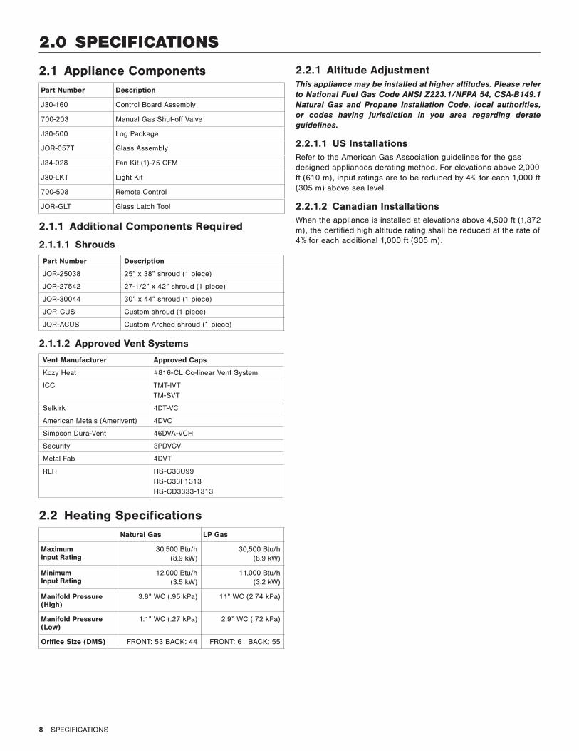
2.1 Appliance ComponentsPart Number Description
J30-160 Control Board Assembly
700-203 Manual Gas Shut-off Valve
J30-500 Log Package
JOR-057T Glass Assembly
J34-028 Fan Kit (1)-75 CFM
J30-LKT Light Kit
700-508 Remote Control
JOR-GLT Glass Latch Tool
2.1.1 Additional Components Required
2.1.1.1 Shrouds
Part Number Description
JOR-25038 25” x 38” shroud (1 piece)
JOR-27542 27-1/2” x 42” shroud (1 piece)
JOR-30044 30” x 44” shroud (1 piece)
JOR-CUS Custom shroud (1 piece)
JOR-ACUS Custom Arched shroud (1 piece)
2.1.1.2 Approved Vent Systems
Vent Manufacturer Approved Caps
Kozy Heat #816-CL Co-linear Vent System
ICC TMT-IVTTM-SVT
Selkirk 4DT-VC
American Metals (Amerivent) 4DVC
Simpson Dura-Vent 46DVA-VCH
Security 3PDVCV
Metal Fab 4DVT
RLH HS-C33U99HS-C33F1313HS-CD3333-1313
2.2 Heating SpecificationsNatural Gas LP Gas
Maximum Input Rating
30,500 Btu/h (8.9 kW)
30,500 Btu/h (8.9 kW)
Minimum Input Rating
12,000 Btu/h (3.5 kW)
11,000 Btu/h (3.2 kW)
Manifold Pressure (High)
3.8” WC (.95 kPa) 11” WC (2.74 kPa)
Manifold Pressure (Low)
1.1” WC (.27 kPa) 2.9” WC (.72 kPa)
Orifice Size (DMS) FRONT: 53 BACK: 44 FRONT: 61 BACK: 55
2.2.1 Altitude AdjustmentThis appliance may be installed at higher altitudes. Please refer to National Fuel Gas Code ANSI Z223.1/NFPA 54, CSA-B149.1 Natural Gas and Propane Installation Code, local authorities, or codes having jurisdiction in you area regarding derate guidelines.
2.2.1.1 US InstallationsRefer to the American Gas Association guidelines for the gas designed appliances derating method. For elevations above 2,000 ft (610 m), input ratings are to be reduced by 4% for each 1,000 ft (305 m) above sea level.
2.2.1.2 Canadian InstallationsWhen the appliance is installed at elevations above 4,500 ft (1,372 m), the certified high altitude rating shall be reduced at the rate of 4% for each additional 1,000 ft (305 m).
SPECIFICATIONS 9
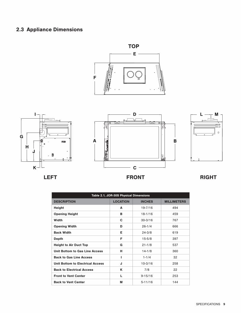
2.3 Appliance Dimensions
Table 2.1, JOR-30S Physical Dimensions
DESCRIPTION LOCATION INCHES MILLIMETERS
Height A 19-7/16 494
Opening Height B 18-1/16 459
Width C 30-3/16 767
Opening Width D 26-1/4 666
Back Width E 24-3/8 619
Depth F 15-5/8 397
Height to Air Duct Top G 21-1/8 537
Unit Bottom to Gas Line Access H 14-1/8 360
Back to Gas Line Access I 1-1/4 32
Unit Bottom to Electrical Access J 10-3/16 258
Back to Electrical Access K 7/8 22
Front to Vent Center L 9-15/16 253
Back to Vent Center M 5-11/16 144
A B
C
DI
G
HJ
K
F
E
L M
TOP
LEFT FRONT RIGHT
10 SPECIFICATIONS
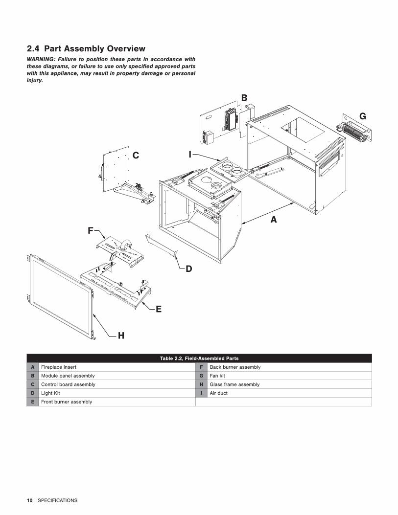
2.4 Part Assembly OverviewWARNING: Failure to position these parts in accordance with these diagrams, or failure to use only specified approved parts with this appliance, may result in property damage or personal injury.
Table 2.2, Field-Assembled Parts
A Fireplace insert F Back burner assembly
B Module panel assembly G Fan kit
C Control board assembly H Glass frame assembly
D Light Kit I Air duct
E Front burner assembly
H
E
F
D
C I
B
A
G
SPECIFICATIONS 11
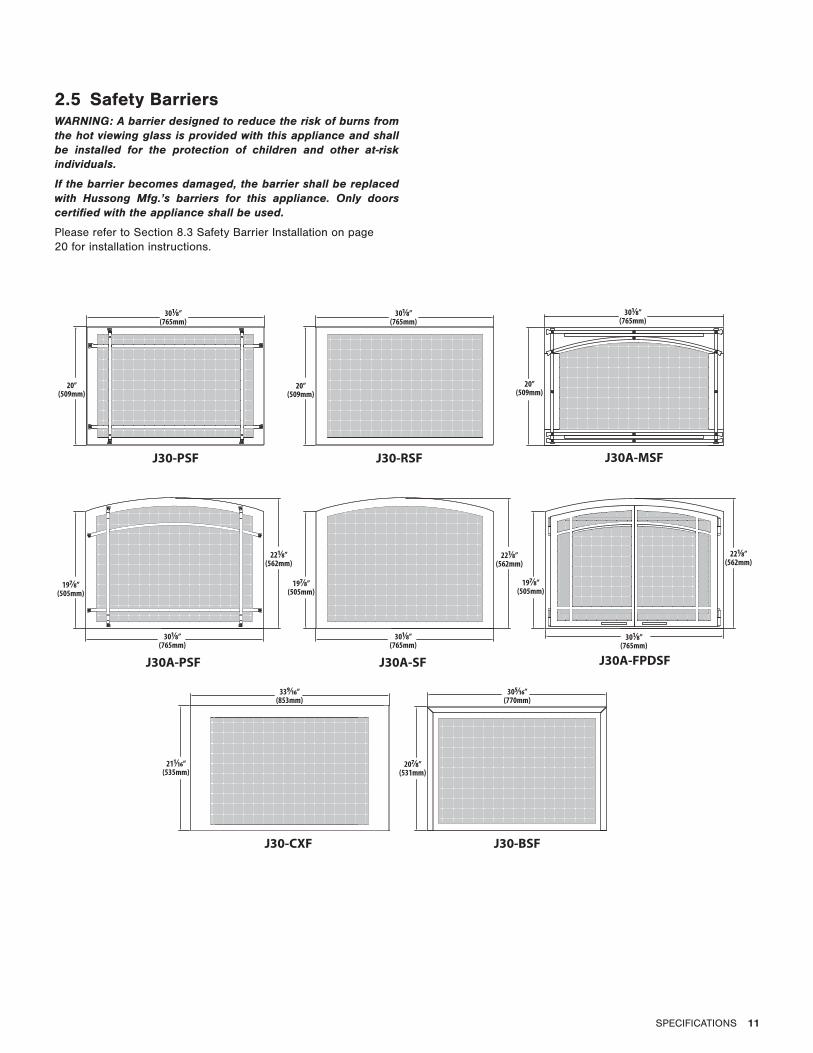
2.5 Safety BarriersWARNING: A barrier designed to reduce the risk of burns from the hot viewing glass is provided with this appliance and shall be installed for the protection of children and other at-risk individuals.
If the barrier becomes damaged, the barrier shall be replaced with Hussong Mfg.’s barriers for this appliance. Only doors certified with the appliance shall be used.
Please refer to Section 8.3 Safety Barrier Installation on page 20 for installation instructions.
20”(509mm)
301⁄8”(765mm)
197⁄8”(505mm)
301⁄8”(765mm)
221⁄8”(562mm)
211⁄16”(535mm)
339⁄16”(853mm)
207⁄8”(531mm)
305⁄16”(770mm)
20”(509mm)
20”(509mm)
301⁄8”(765mm)
301⁄8”(765mm)
221⁄8”(562mm)
221⁄8”(562mm)
197⁄8”(505mm)
197⁄8”(505mm)
301⁄8”(765mm)
301⁄8”(765mm)
J30-CXF J30-BSF
J30A-PSF J30A-SF J30A-FPDSF
J30-PSF J30-RSF J30A-MSF
12 EXISTING FIREPLACE REQUIREMENTS
3.0 EXISTING FIREPLACE REQUIREMENTS
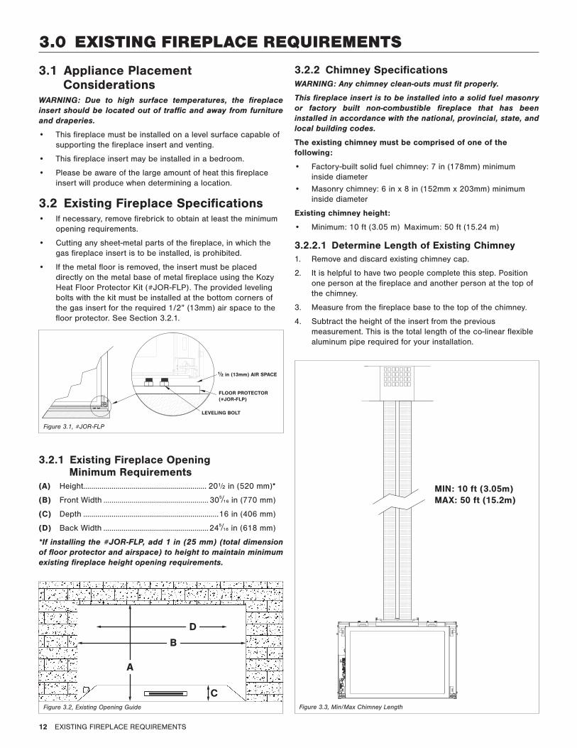
3.1 Appliance Placement Considerations
WARNING: Due to high surface temperatures, the fireplace insert should be located out of traffic and away from furniture and draperies.
• This fireplace must be installed on a level surface capable of supporting the fireplace insert and venting.
• This fireplace insert may be installed in a bedroom.
• Please be aware of the large amount of heat this fireplace insert will produce when determining a location.
3.2 Existing Fireplace Specifications• If necessary, remove firebrick to obtain at least the minimum
opening requirements.
• Cutting any sheet-metal parts of the fireplace, in which the gas fireplace insert is to be installed, is prohibited.
• If the metal floor is removed, the insert must be placed directly on the metal base of metal fireplace using the Kozy Heat Floor Protector Kit (#JOR-FLP). The provided leveling bolts with the kit must be installed at the bottom corners of the gas insert for the required 1/2” (13mm) air space to the floor protector. See Section 3.2.1.
3.2.1 Existing Fireplace Opening Minimum Requirements
(A) Height............................................................. 20½ in (520 mm)*
(B) Front Width .................................................... 305/16 in (770 mm)
(C) Depth ...................................................................16 in (406 mm)
(D) Back Width ....................................................245/16 in (618 mm)
*If installing the #JOR-FLP, add 1 in (25 mm) (total dimension of floor protector and airspace) to height to maintain minimum existing fireplace height opening requirements.
C
A
B
D
3.2.2 Chimney SpecificationsWARNING: Any chimney clean-outs must fit properly.
This fireplace insert is to be installed into a solid fuel masonry or factory built non-combustible fireplace that has been installed in accordance with the national, provincial, state, and local building codes.
The existing chimney must be comprised of one of the following:
• Factory-built solid fuel chimney: 7 in (178mm) minimum inside diameter
• Masonry chimney: 6 in x 8 in (152mm x 203mm) minimum inside diameter
Existing chimney height:
• Minimum: 10 ft (3.05 m) Maximum: 50 ft (15.24 m)
3.2.2.1 Determine Length of Existing Chimney1. Remove and discard existing chimney cap.
2. It is helpful to have two people complete this step. Position one person at the fireplace and another person at the top of the chimney.
3. Measure from the fireplace base to the top of the chimney.
4. Subtract the height of the insert from the previous measurement. This is the total length of the co-linear flexible aluminum pipe required for your installation.
MIN: 10 ft (3.05m)MAX: 50 ft (15.2m)
½ in (13mm) AIR SPACE
FLOOR PROTECTOR(#JOR-FLP)
LEVELING BOLT
Figure 3.1, #JOR-FLP
Figure 3.2, Existing Opening Guide Figure 3.3, Min/Max Chimney Length
TERMINATION LOCATION 13
4.0 TERMINATION LOCATION
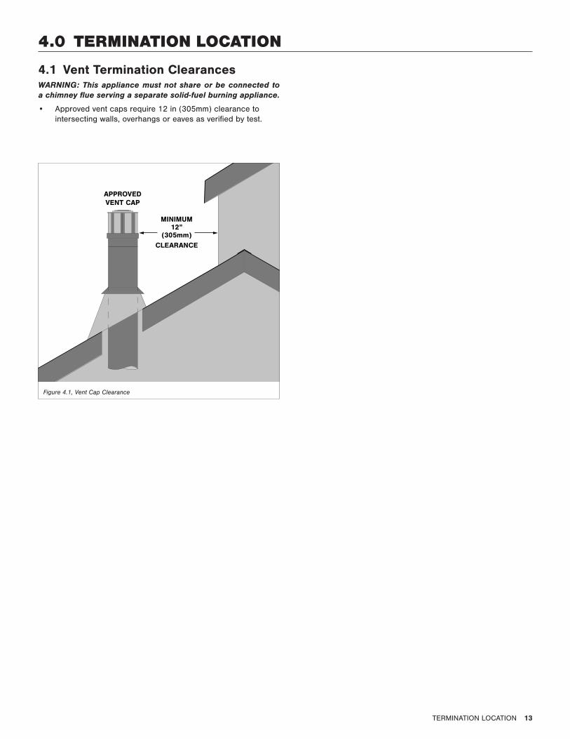
4.1 Vent Termination ClearancesWARNING: This appliance must not share or be connected to a chimney flue serving a separate solid-fuel burning appliance.
• Approved vent caps require 12 in (305mm) clearance to intersecting walls, overhangs or eaves as verified by test.
12”(305mm)
APPROVED VENT CAP
MINIMUM
CLEARANCE
Figure 4.1, Vent Cap Clearance
14 INSTALLATION PREPARATION
5.0 INSTALLATION PREPARATIONNOTE: This gas fireplace insert is approved for installation in masonry and factory-built solid fuel burning fireplaces.
ATTENTION: Any removed parts must be capable of re-installation if this insert is ever removed. Removal of rivets or screws is acceptable.
5.1 Inspect and Clean Existing Chimney• Verify existing chimney is constructed of non-combustible
material.
• Verify existing chimney is clean and in good working order. Clean existing chimney and fireplace to prevent a creosote odor from entering the home.
• Verify combustible mantel and sidewall clearances comply with Section 8.1 Clearances to Combustibles on page 19.
• Any smoke shelves, shields, and baffles may be removed if attached by mechanical fasteners.
• The refractory, glass doors, screen rails, screen mesh, and log grates may be removed from existing fireplace before installing this gas fireplace insert.
5.2 Flue Damper• The fireplace flue damper can be fully blocked open, or
removed for installation of this gas fireplace insert. Remove existing chimney cap.
5.3 Gas Line• A gas line must be able to be installed to the insert. Refer to
Section 7.0 Gas Line Connection on page 18.
• If the factory-built fireplace has no gas access hole(s) provided, an access hole of 1½ in. (37.5 mm) or less may be drilled through the lower sides or bottom of the firebox in a proper workmanship like manner. The access hole must be plugged with non-combustible insulation after the gas supply line has been installed.
• Run gas line to the gas fireplace insert through the gas line hole provided. Do not run gas line in a manner that would obstruct fan operation.
• If the gas fireplace insert is to be installed into minimum opening dimensions, the gas line may need to be run after appliance placement due to space limitations.
5.4 Electrical Wiring• Provisions must be made to provide electrical power for
appliance operation.
• Refer to Section 2.3 Appliance Dimensions on page 9 for electrical outlet box location to run any necessary electrical wiring to the gas fireplace insert.
5.5 Fireplace Conversion • Mechanically attach the label with the following warning to
at the bottom existing firebox so it will be visible if this gas fireplace insert is removed.
WARNING: This fireplace has been converted for use with a gas fireplace insert only and cannot be used for burning wood or solid fuels unless all original parts have been replaced, and the fireplace re-approved by the Authority Having Jurisdiction.
INSTALLATION 15
6.0 INSTALLATION
D
A
C
B
C
E
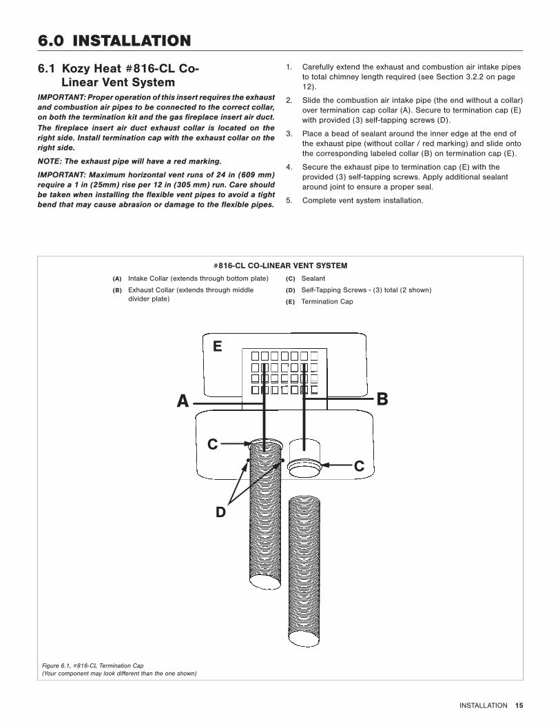
#816-CL CO-LINEAR VENT SYSTEM
(A) Intake Collar (extends through bottom plate)
(B) Exhaust Collar (extends through middle divider plate)
(C) Sealant
(D) Self-Tapping Screws - (3) total (2 shown)
(E) Termination Cap
Figure 6.1, #816-CL Termination Cap (Your component may look different than the one shown)
6.1 Kozy Heat #816-CL Co-Linear Vent System
IMPORTANT: Proper operation of this insert requires the exhaust and combustion air pipes to be connected to the correct collar, on both the termination kit and the gas fireplace insert air duct.The fireplace insert air duct exhaust collar is located on the right side. Install termination cap with the exhaust collar on the right side.
NOTE: The exhaust pipe will have a red marking.
IMPORTANT: Maximum horizontal vent runs of 24 in (609 mm) require a 1 in (25mm) rise per 12 in (305 mm) run. Care should be taken when installing the flexible vent pipes to avoid a tight bend that may cause abrasion or damage to the flexible pipes.
1. Carefully extend the exhaust and combustion air intake pipes to total chimney length required (see Section 3.2.2 on page 12).
2. Slide the combustion air intake pipe (the end without a collar) over termination cap collar (A). Secure to termination cap (E) with provided (3) self-tapping screws (D).
3. Place a bead of sealant around the inner edge at the end of the exhaust pipe (without collar / red marking) and slide onto the corresponding labeled collar (B) on termination cap (E).
4. Secure the exhaust pipe to termination cap (E) with the provided (3) self-tapping screws. Apply additional sealant around joint to ensure a proper seal.
5. Complete vent system installation.
16 INSTALLATION
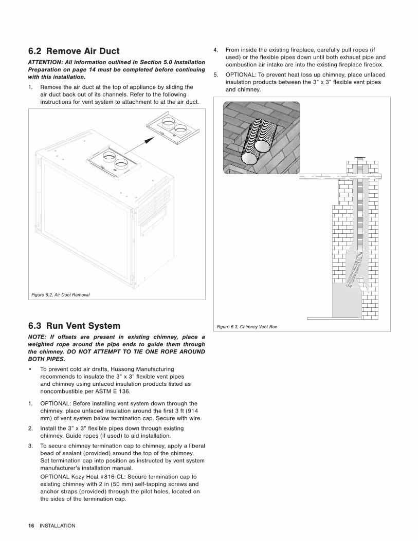
6.3 Run Vent SystemNOTE: If offsets are present in existing chimney, place a weighted rope around the pipe ends to guide them through the chimney. DO NOT ATTEMPT TO TIE ONE ROPE AROUND BOTH PIPES.
• To prevent cold air drafts, Hussong Manufacturing recommends to insulate the 3” x 3” flexible vent pipes and chimney using unfaced insulation products listed as noncombustible per ASTM E 136.
1. OPTIONAL: Before installing vent system down through the chimney, place unfaced insulation around the first 3 ft (914 mm) of vent system below termination cap. Secure with wire.
2. Install the 3” x 3” flexible pipes down through existing chimney. Guide ropes (if used) to aid installation.
3. To secure chimney termination cap to chimney, apply a liberal bead of sealant (provided) around the top of the chimney. Set termination cap into position as instructed by vent system manufacturer’s installation manual.
OPTIONAL Kozy Heat #816-CL: Secure termination cap to existing chimney with 2 in (50 mm) self-tapping screws and anchor straps (provided) through the pilot holes, located on the sides of the termination cap.
Figure 6.3, Chimney Vent Run
6.2 Remove Air Duct ATTENTION: All information outlined in Section 5.0 Installation Preparation on page 14 must be completed before continuing with this installation.
1. Remove the air duct at the top of appliance by sliding the air duct back out of its channels. Refer to the following instructions for vent system to attachment to at the air duct.
Figure 6.2, Air Duct Removal
4. From inside the existing fireplace, carefully pull ropes (if used) or the flexible pipes down until both exhaust pipe and combustion air intake are into the existing fireplace firebox.
5. OPTIONAL: To prevent heat loss up chimney, place unfaced insulation products between the 3” x 3” flexible vent pipes and chimney.
INSTALLATION 17
ALIGNEDGAS INSERT
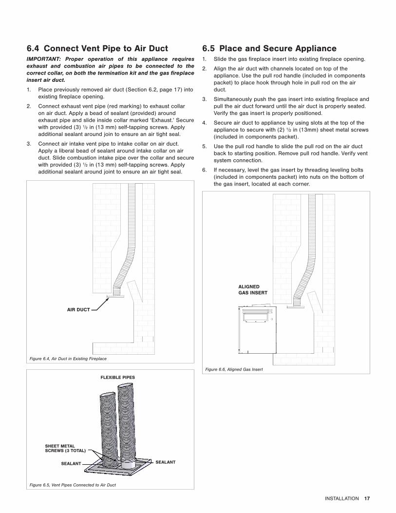
6.4 Connect Vent Pipe to Air DuctIMPORTANT: Proper operation of this appliance requires exhaust and combustion air pipes to be connected to the correct collar, on both the termination kit and the gas fireplace insert air duct.
1. Place previously removed air duct (Section 6.2, page 17) into existing fireplace opening.
2. Connect exhaust vent pipe (red marking) to exhaust collar on air duct. Apply a bead of sealant (provided) around exhaust pipe and slide inside collar marked ‘Exhaust.’ Secure with provided (3) ½ in (13 mm) self-tapping screws. Apply additional sealant around join to ensure an air tight seal.
3. Connect air intake vent pipe to intake collar on air duct. Apply a liberal bead of sealant around intake collar on air duct. Slide combustion intake pipe over the collar and secure with provided (3) ½ in (13 mm) self-tapping screws. Apply additional sealant around joint to ensure an air tight seal.
AIR DUCT
Figure 6.4, Air Duct in Existing Fireplace
FLEXIBLE PIPES
SHEET METAL SCREWS (3 TOTAL)
SEALANT SEALANT
6.5 Place and Secure Appliance1. Slide the gas fireplace insert into existing fireplace opening.
2. Align the air duct with channels located on top of the appliance. Use the pull rod handle (included in components packet) to place hook through hole in pull rod on the air duct.
3. Simultaneously push the gas insert into existing fireplace and pull the air duct forward until the air duct is properly seated. Verify the gas insert is properly positioned.
4. Secure air duct to appliance by using slots at the top of the appliance to secure with (2) ½ in (13mm) sheet metal screws (included in components packet).
5. Use the pull rod handle to slide the pull rod on the air duct back to starting position. Remove pull rod handle. Verify vent system connection.
6. If necessary, level the gas insert by threading leveling bolts (included in components packet) into nuts on the bottom of the gas insert, located at each corner.
Figure 6.5, Vent Pipes Connected to Air Duct
Figure 6.6, Aligned Gas Insert

18 GAS LINE CONNECTION
7.0 GAS LINE CONNECTION
7.1 Gas Conversion (sold separately)ATTENTION: The conversion shall be carried out in accordance with the requirements of the provincial authorities having jurisdiction and in accordance with the requirements of the ANSI Z223.1 installation code.
This fireplace is manufactured for use with natural gas. Follow the instructions included with the conversion kit if converting to LP gas.
7.2 Gas Line InstallationCAUTION: Installation of the gas line must only be done by a qualified person in accordance with local building codes, if any. If not, follow ANSI 223.1. Commonwealth of Massachusetts installations must be done by a licensed plumber or gas fitter.
NOTE: The appliance and its individual shutoff valve must be disconnected from the gas supply piping system during any pressure testing of that system at pressures in excess of ½ psi (3.5 kPa). For test pressures equal to or less than ½ psi (3.5 kPa), the appliance must be isolated from the gas supply piping system by closing its individual manual shut-off valve.
• A listed (and Commonwealth of Massachusetts approved) ½ in. (13 mm) tee handle manual shut-off valve and flexible gas connector are to be connected to the ½ in. (13 mm) control valve inlet. If substituting for these components, please consult local codes for compliance.
• If installing this insert into minimum opening dimensions, the gas line may need to be run after placement due to space limitations. See Section 3.2.1 Existing Fireplace Opening Minimum Requirements on page 12.
• This fireplace is equipped with a ⅜” (10 mm) x 18” (457 mm) long flexible gas connector and manual shut-off valve.
• Run gas line into fireplace. The gas line should be run to the point of connection where the shut-off valve and flexible gas line will connect.
• Do not run gas line in a manner that would obstruct fan operation.
• For high altitude installations, consult the local gas distributor or the authority having jurisdiction for proper rating methods.
Table 7.1, Inlet Gas Supply Pressures
Fuel Minimum Pressure Maximum Pressure
Natural Gas 5” WC (1.25 kPa) 10.5” WC (2.62 kPa)
LP Gas 11” WC (2.74 kPa) 13” WC (3.24 kPa)
FACING AND FINISHING 19
8.0 FACING AND FINISHING
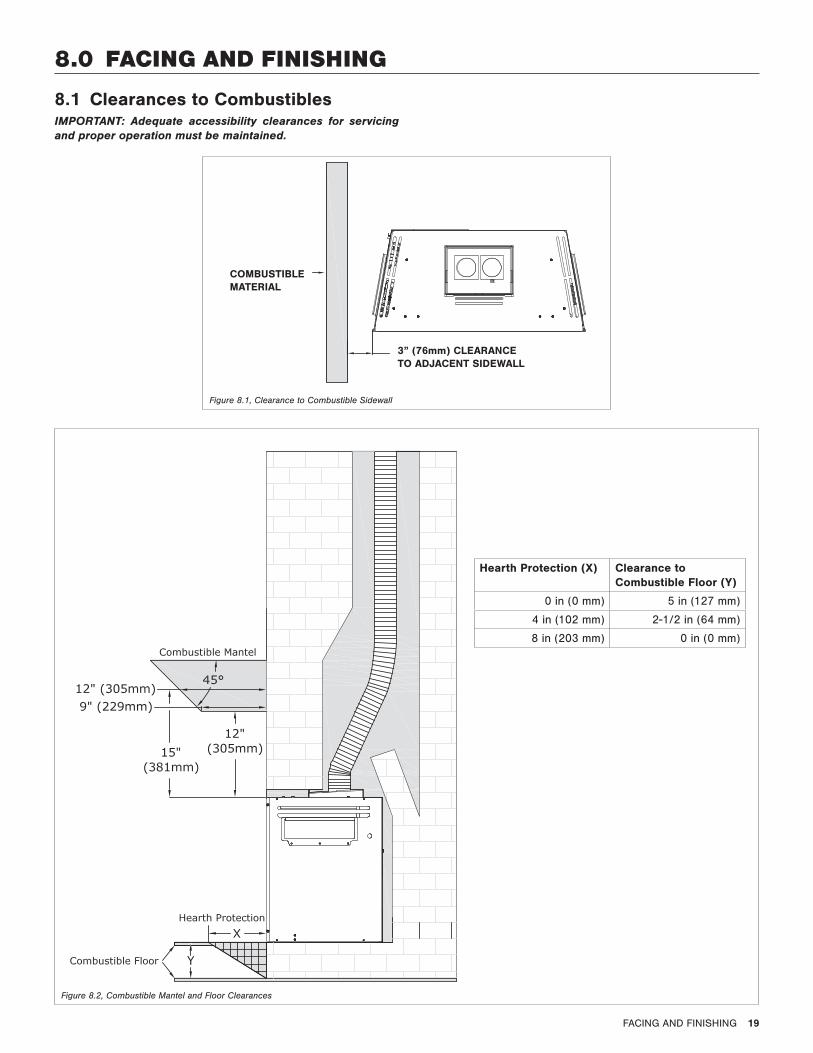
8.1 Clearances to CombustiblesIMPORTANT: Adequate accessibility clearances for servicing and proper operation must be maintained.
COMBUSTIBLEMATERIAL
3” (76mm) CLEARANCE TO ADJACENT SIDEWALL
Hearth Protection (X) Clearance to Combustible Floor (Y)
0 in (0 mm) 5 in (127 mm)
4 in (102 mm) 2-1/2 in (64 mm)
8 in (203 mm) 0 in (0 mm)
Figure 8.1, Clearance to Combustible Sidewall
Figure 8.2, Combustible Mantel and Floor Clearances

20 FACING AND FINISHING
8.2 Shroud InstallationCAUTION: Trim panels or surrounds must not seal ventilation openings in existing fireplace that this appliance is installed in. Draft relief openings must not be covered or blocked.
WARNING: The flow of combustion and ventilation air must not be obstructed.
For shrouds JOR-25038, JOR-27542, JOR-30044, JOR-CUS, and JOR-ACUS.
1. Remove glass frame assembly.
2. Align leg section holes on the shroud to the corresponding mounting nuts in mounting brackets on each side of the insert metal cabinet.
3. Secure with (4) phillips truss head screws (provided).
4. Reinstall glass frame assembly.
8.3 Safety Barrier InstallationFor safety barriers J30-PSF, J30-RSF, J30A-MSF, J30A-PSF, J30A-SF, J30A-FPDSF, J30-CXF, and J30-BSF.
1. Locate the (4) slots on the glass frame (2 each side).
2. Align the tabs located on the back of the safety barrier with the slots on the glass frame.
3. Raise the safety barrier slightly into the slots and allow the tabs to lower into position.
• To remove safety screen: lift the screen up and out of slots.
Figure 8.3, Aligned Mounting Nuts and Brackets
GAS FIREPLACE INSERT SETUP 21
9.0 GAS FIREPLACE INSERT SETUP
9.1 Glass AssemblyWARNING: Do not operate this fireplace with the glass removed, cracked, or broken. Replacement of the glass assembly should be done by a licensed or qualified service person.
9.1.1 Remove Glass AssemblyWARNING: Do not remove the glass assembly when hot.
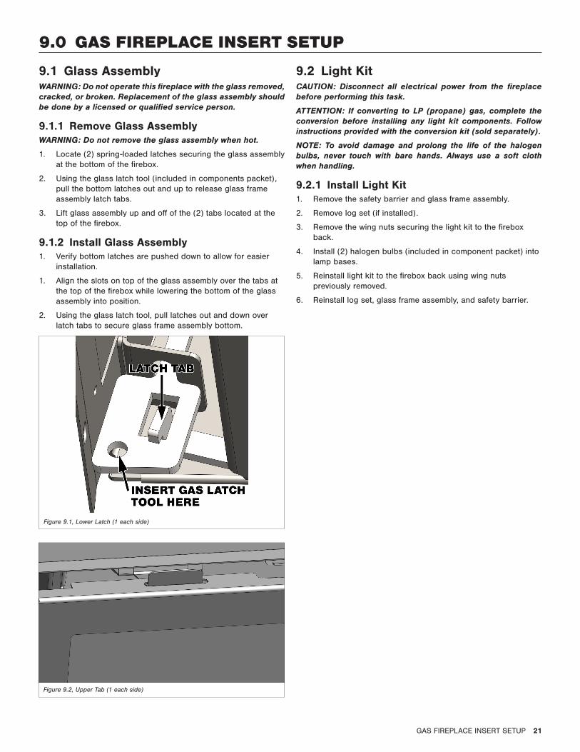
1. Locate (2) spring-loaded latches securing the glass assembly at the bottom of the firebox.
2. Using the glass latch tool (included in components packet), pull the bottom latches out and up to release glass frame assembly latch tabs.
3. Lift glass assembly up and off of the (2) tabs located at the top of the firebox.
9.1.2 Install Glass Assembly1. Verify bottom latches are pushed down to allow for easier
installation.
1. Align the slots on top of the glass assembly over the tabs at the top of the firebox while lowering the bottom of the glass assembly into position.
2. Using the glass latch tool, pull latches out and down over latch tabs to secure glass frame assembly bottom.
Figure 9.1, Lower Latch (1 each side)
Figure 9.2, Upper Tab (1 each side)
9.2 Light KitCAUTION: Disconnect all electrical power from the fireplace before performing this task.
ATTENTION: If converting to LP (propane) gas, complete the conversion before installing any light kit components. Follow instructions provided with the conversion kit (sold separately).
NOTE: To avoid damage and prolong the life of the halogen bulbs, never touch with bare hands. Always use a soft cloth when handling.
9.2.1 Install Light Kit1. Remove the safety barrier and glass frame assembly.
2. Remove log set (if installed).
3. Remove the wing nuts securing the light kit to the firebox back.
4. Install (2) halogen bulbs (included in component packet) into lamp bases.
5. Reinstall light kit to the firebox back using wing nuts previously removed.
6. Reinstall log set, glass frame assembly, and safety barrier.
22 GAS FIREPLACE INSERT SETUP
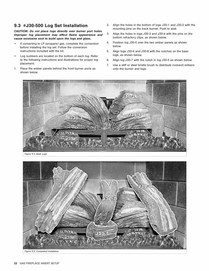
9.3 #J30-500 Log Set InstallationCAUTION: Do not place logs directly over burner port holes. Improper log placement may affect flame appearance and cause excessive soot to build upon the logs and glass.
• If converting to LP (propane) gas, complete the conversion before installing the log set. Follow the conversion instructions included with the kit.
• Log numbers are located on the bottom of each log. Refer to the following instructions and illustrations for proper log placement.
1. Place the ember panels behind the front burner ports as shown below.
2. Align the holes in the bottom of logs J30-1 and J30-2 with the mounting pins on the back burner. Push to seat.
3. Align the holes in logs J30-3 and J30-4 with the pins on the bottom refractory clips, as shown below.
4. Position log J30-5 over the two ember panels as shown below.
5. Align logs J30-6 and J30-8 with the notches on the base logs, as shown below.
6. Align log J30-7 with the notch in log J30-5 as shown below.
7. Use a stiff or steel bristle brush to distribute rockwoll embers onto the burner and logs.
Figure 9.3, Base Logs
Figure 9.4, Completed Installation

GAS FIREPLACE INSERT SETUP 23
9.4 Control Board Removal and Installation
WARNING: If burner and/or pilot have been burning, use appropriate protection to avoid burns or damage to personal property before removing any components. DO NOT OPERATE THIS APPLIANCE WITHOUT THE SEALING GASKET (LOCATED UNDER THE CONTROL BOARD) IN PLACE. IF GASKETING IS DAMAGED, IT MUST BE REPLACED.
CAUTION: Check all connections for leaks with soapy water, whether field or factory made.
9.4.1 Control Board Removal1. Disconnect electrical power.
2. Locate the main shut-off valve upstream of the appliance connector and close valve.
3. Remove safety barrier and glass frame assembly.
4. Remove log set.
5. Remove refractory panel set. Loosen screws securing refractory clips on the baffle (2 each side) to remove left and right panels.
6. Remove back burner assembly (2) screws each side.
7. Remove front burner assembly by lifting it up and off the front burner orifice.
8. Remove (10) screws securing the control board on the left side of the firebox.
9. Pull out control board out to reveal gas line to disconnect the gas line flex tube from fireplace valve.
9.4.2 Control Board Installation1. Place control board on the left side of the firebox and
reconnect gas line to fireplace valve.
2. Verify sealing gasket is in place. Secure board with (10) screws previously removed.
3. Reinstall front burner by positioning the venturi over the front burner orifice, and set into place.
4. Reinstall back burner. Position the burner tube venturi over the back burner orifice and secure with (2) screws previously removed.
5. Reinstall refractory panel set.
6. Reinstall log set.
7. Reconnect electrical power.
8. Reinstall the glass frame assembly and safety barrier.
9. Verify proper log placement, operation of fireplace, and any electrical components.
ON
OFF
Figure 9.5, Control Board Removal and Installation
FRONT BURNER ASSEMBLY
BACK BURNER ASSEMBLY
24 ELECTRICAL INFORMATION
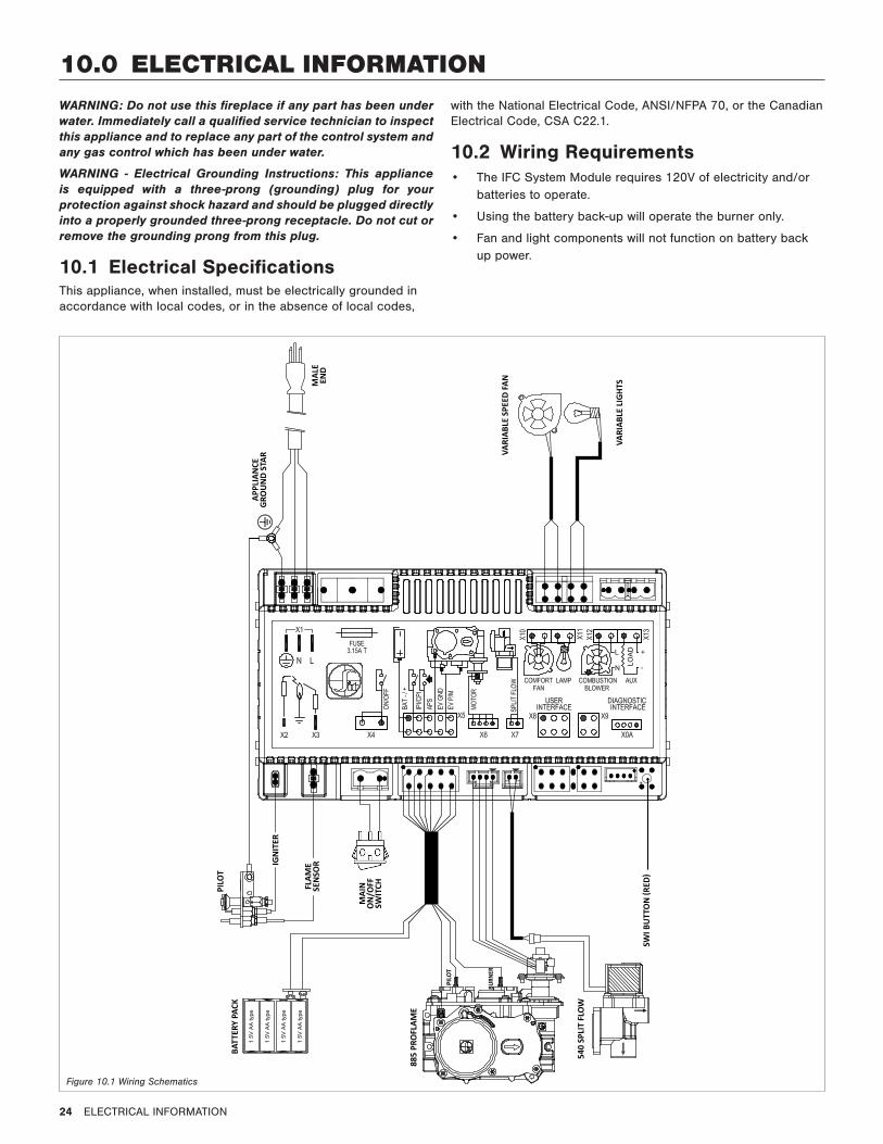
10.0 ELECTRICAL INFORMATIONWARNING: Do not use this fireplace if any part has been under water. Immediately call a qualified service technician to inspect this appliance and to replace any part of the control system and any gas control which has been under water.
WARNING - Electrical Grounding Instructions: This appliance is equipped with a three-prong (grounding) plug for your protection against shock hazard and should be plugged directly into a properly grounded three-prong receptacle. Do not cut or remove the grounding prong from this plug.
10.1 Electrical SpecificationsThis appliance, when installed, must be electrically grounded in accordance with local codes, or in the absence of local codes,
with the National Electrical Code, ANSI/NFPA 70, or the Canadian Electrical Code, CSA C22.1.
10.2 Wiring Requirements• The IFC System Module requires 120V of electricity and/or
batteries to operate.
• Using the battery back-up will operate the burner only.
• Fan and light components will not function on battery back up power.
885
PRO
FLAM
E
MAI
N
ON
/OFF
SW
ITCHFL
AME
SEN
SORIG
NIT
ER
PILO
TBA
TTER
Y PA
CK
PILO
T
BURN
ER
540
SPLI
T FL
OW
SWI B
UTT
ON
(RED
)
VARI
ABLE
SPE
ED FA
N
VARI
ABLE
LIG
HTS
APPL
IAN
CEG
ROU
ND
STAR
MAL
EEN
D
Figure 10.1 Wiring Schematics
OPERATING INSTRUCTIONS 25
WARNINGDo not operate appliance with the glass front removed, cracked, or broken. Replacement of the glass should be done by a licensed or qualified service person.
Under no circumstances should any solid fuel (wood, coal, paper, cardboard, etc.) be used in this appliance.
Children and adults should be alerted to the hazards of high surface temperature and should stay away to avoid burns or clothing ignition.
CAUTIONClothing or other flammable material should not be placed on or near the appliance.
Young children should be carefully supervised when they are in the same room as the appliance. Toddlers, young children and others may be susceptible to accidental contact burns. A physical barrier is recommended if there are at risk individuals in the house. To restrict access to a fireplace or stove, install an adjustable safety gate to keep toddler, young children and other at risk individuals out of the room and away from hot surfaces.
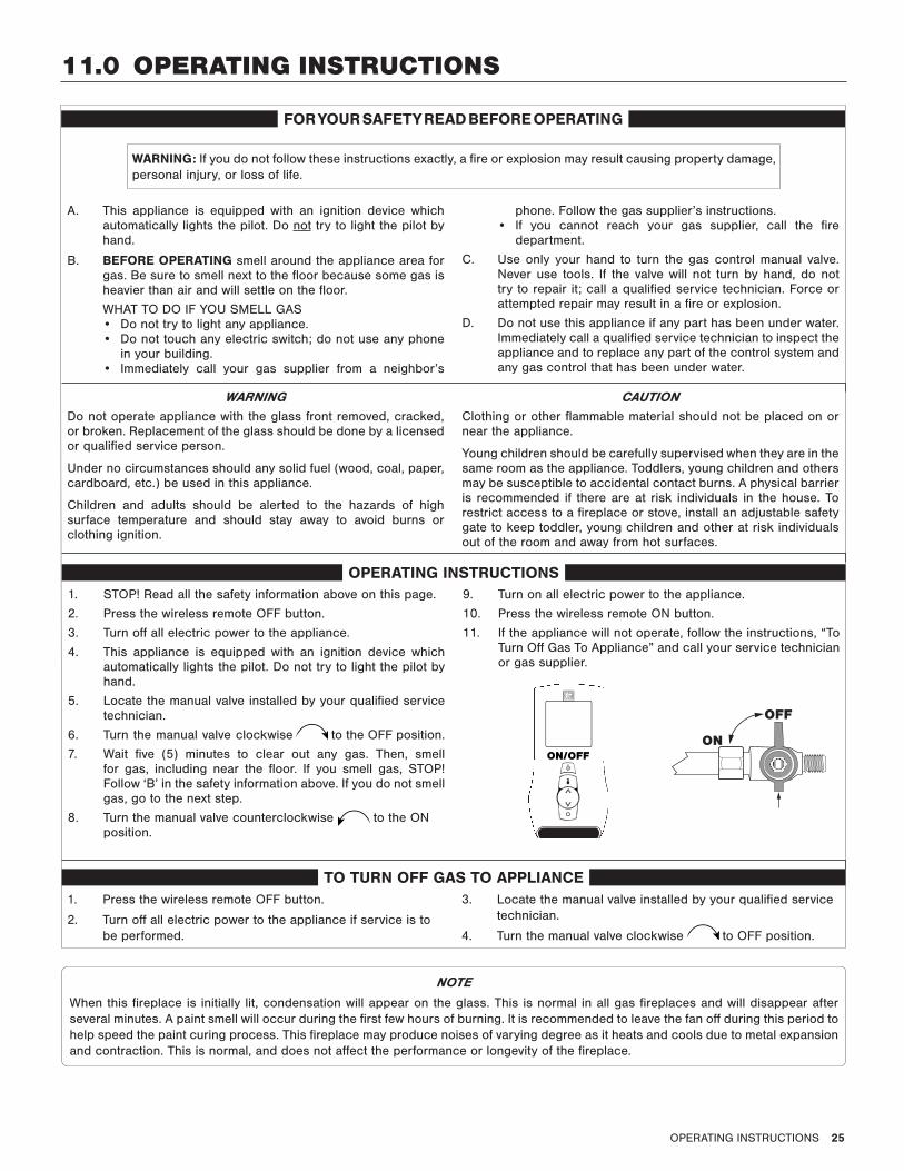
WARNING: If you do not follow these instructions exactly, a fire or explosion may result causing property damage, personal injury, or loss of life.
1. STOP! Read all the safety information above on this page.
2. Press the wireless remote OFF button.
3. Turn off all electric power to the appliance.
4. This appliance is equipped with an ignition device which automatically lights the pilot. Do not try to light the pilot by hand.
5. Locate the manual valve installed by your qualified service technician.
6. Turn the manual valve clockwise to the OFF position.
7. Wait five (5) minutes to clear out any gas. Then, smell for gas, including near the floor. If you smell gas, STOP! Follow ‘B’ in the safety information above. If you do not smell gas, go to the next step.
8. Turn the manual valve counterclockwise to the ON position.
9. Turn on all electric power to the appliance.
10. Press the wireless remote ON button.
11. If the appliance will not operate, follow the instructions, “To Turn Off Gas To Appliance” and call your service technician or gas supplier.
OPERATING INSTRUCTIONS
NOTE
When this fireplace is initially lit, condensation will appear on the glass. This is normal in all gas fireplaces and will disappear after several minutes. A paint smell will occur during the first few hours of burning. It is recommended to leave the fan off during this period to help speed the paint curing process. This fireplace may produce noises of varying degree as it heats and cools due to metal expansion and contraction. This is normal, and does not affect the performance or longevity of the fireplace.
A. This appliance is equipped with an ignition device which automatically lights the pilot. Do not try to light the pilot by hand.
B. BEFORE OPERATING smell around the appliance area for gas. Be sure to smell next to the floor because some gas is heavier than air and will settle on the floor.
WHAT TO DO IF YOU SMELL GAS• Do not try to light any appliance.• Do not touch any electric switch; do not use any phone
in your building.• Immediately call your gas supplier from a neighbor’s
phone. Follow the gas supplier’s instructions. • If you cannot reach your gas supplier, call the fire
department.
C. Use only your hand to turn the gas control manual valve. Never use tools. If the valve will not turn by hand, do not try to repair it; call a qualified service technician. Force or attempted repair may result in a fire or explosion.
D. Do not use this appliance if any part has been under water. Immediately call a qualified service technician to inspect the appliance and to replace any part of the control system and any gas control that has been under water.
ON/OFF ON
OFF
1. Press the wireless remote OFF button.
2. Turn off all electric power to the appliance if service is to be performed.
3. Locate the manual valve installed by your qualified service technician.
4. Turn the manual valve clockwise to OFF position.
FOR YOUR SAFETY READ BEFORE OPERATING
TO TURN OFF GAS TO APPLIANCE
11.0 OPERATING INSTRUCTIONS

26 OPERATING INSTRUCTIONS
11.1 Setup Proflame 2 IFC Module1. Set the main ON/OFF rocker switch in the OFF position.
2. Install (4) AA batteries (included in the components packet) into backup battery holder on the control module.
3. Install (3) AAA batteries (included in the components packet) in the remote control battery bay, located at the base of the remote.
4. Connect the IFC Module to an AC power supply.
11.2 Initialize the Control SystemIMPORTANT: Remove all packaging and combustible material from the firebox before initializing the control system.
NOTE: Performing the next steps will initiate pilot start-up in manual mode, where the pilot igniter will spark repeatedly. The pilot will ignite if gas is supplied to the fireplace.
1. Locate the red SW1 button the IFC module.
2. Press the button. The IFC module will BEEP (3) times and illuminate an amber LED. This indicates the receiver is ready to synchronize with the transmitter.
3. Within (5) seconds, push the ON/OFF button on the remote control. The receiver will BEEP (4) times to indicate the transmitter’s command is accepted, and is set to the transmitter’s particular code. The pilot will automatically ignite.
4. Press the remote control ON/OFF button again. The pilot will extinguish, confirming the remote control command. The control system is now initialized.
5. Set the main ON/OFF rocker switch to ON position for remote control operation of the main burner and fireplace features.
11.3 Reset the System for Manual Operation
1. Set the ON/OFF rocker switch to OFF position.
2. Press the red SWI button on the IFC module until it emits (3) beeps and an amber LED is illuminated.
3. Within (5) seconds, press the red SWI button again. This will close synchronization with the remote control. The pilot will automatically light.
• Turn the main burner ON by setting the ON/OFF switch in ON position. The main burner will only operate on HI.
Figure 11.1, IFC Module
• Turn the main burner OFF by setting the ON/OFF switch in the OFF position. The pilot will remain lit even if burner is turned off, provided CPI mode is turned on.
11.4 Automatic Safety Restart• This system will execute an automatic turn OFF command
within (24) hours of a continued pilot flame ignition. This allows the system to verify correct safety functions.
• After the turn OFF sequence is completed, the IFC module will re-execute the latest command.
11.5 Backup Battery Operation This appliance will operate on the backup battery pack when electric power is interrupted, or in a power outage. The lifespan of the backup batteries depend on various factors, such as the quality of the batteries, number of ignitions, et cetera.
• When the backup battery pack is low, the IFC module will emit a double-beep while receiving an ON/OFF command.
• No commands will be accepted after this alert until the back up batteries are replaced.
• Once replaced, the IFC module will emit a ‘beep’ as soon as it is powered.
SW1 BUTTON
LEDs
OPERATING INSTRUCTIONS 27
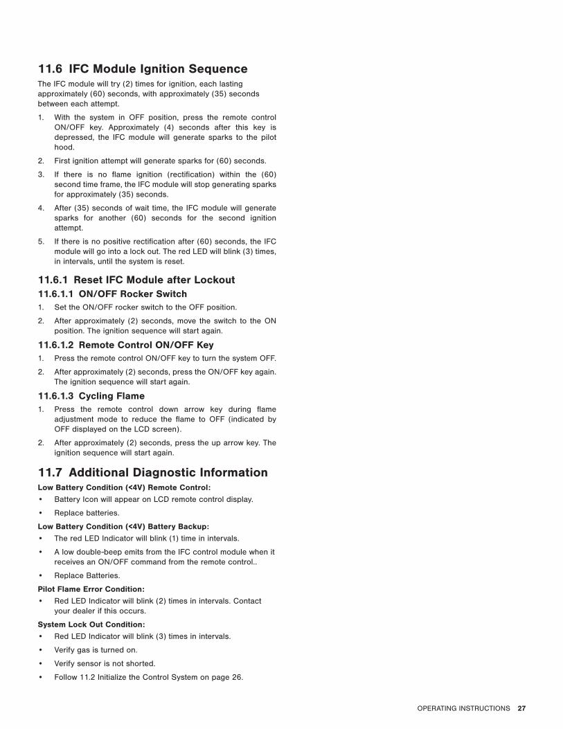
11.6 IFC Module Ignition SequenceThe IFC module will try (2) times for ignition, each lasting approximately (60) seconds, with approximately (35) seconds between each attempt.
1. With the system in OFF position, press the remote control ON/OFF key. Approximately (4) seconds after this key is depressed, the IFC module will generate sparks to the pilot hood.
2. First ignition attempt will generate sparks for (60) seconds.
3. If there is no flame ignition (rectification) within the (60) second time frame, the IFC module will stop generating sparks for approximately (35) seconds.
4. After (35) seconds of wait time, the IFC module will generate sparks for another (60) seconds for the second ignition attempt.
5. If there is no positive rectification after (60) seconds, the IFC module will go into a lock out. The red LED will blink (3) times, in intervals, until the system is reset.
11.6.1 Reset IFC Module after Lockout11.6.1.1 ON/OFF Rocker Switch1. Set the ON/OFF rocker switch to the OFF position.
2. After approximately (2) seconds, move the switch to the ON position. The ignition sequence will start again.
11.6.1.2 Remote Control ON/OFF Key1. Press the remote control ON/OFF key to turn the system OFF.
2. After approximately (2) seconds, press the ON/OFF key again. The ignition sequence will start again.
11.6.1.3 Cycling Flame1. Press the remote control down arrow key during flame
adjustment mode to reduce the flame to OFF (indicated by OFF displayed on the LCD screen).
2. After approximately (2) seconds, press the up arrow key. The ignition sequence will start again.
11.7 Additional Diagnostic InformationLow Battery Condition (<4V) Remote Control: • Battery Icon will appear on LCD remote control display.
• Replace batteries.
Low Battery Condition (<4V) Battery Backup:• The red LED Indicator will blink (1) time in intervals.
• A low double-beep emits from the IFC control module when it receives an ON/OFF command from the remote control..
• Replace Batteries.
Pilot Flame Error Condition: • Red LED Indicator will blink (2) times in intervals. Contact
your dealer if this occurs.
System Lock Out Condition: • Red LED Indicator will blink (3) times in intervals.
• Verify gas is turned on.
• Verify sensor is not shorted.
• Follow 11.2 Initialize the Control System on page 26.
28 OPERATING INSTRUCTIONS
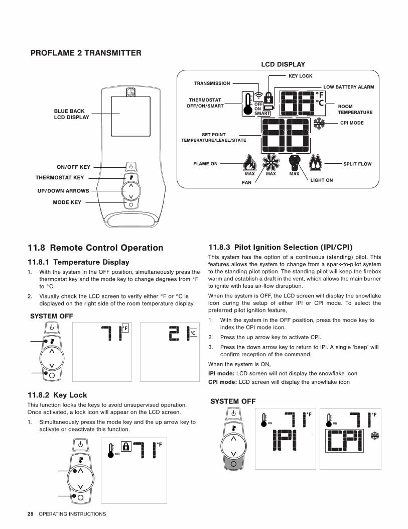
11.8 Remote Control Operation
11.8.1 Temperature Display1. With the system in the OFF position, simultaneously press the
thermostat key and the mode key to change degrees from °F to °C.
2. Visually check the LCD screen to verify either °F or °C is displayed on the right side of the room temperature display.
11.8.2 Key LockThis function locks the keys to avoid unsupervised operation. Once activated, a lock icon will appear on the LCD screen.
1. Simultaneously press the mode key and the up arrow key to activate or deactivate this function.
11.8.3 Pilot Ignition Selection (IPI/CPI) This system has the option of a continuous (standing) pilot. This features allows the system to change from a spark-to-pilot system to the standing pilot option. The standing pilot will keep the firebox warm and establish a draft in the vent, which allows the main burner to ignite with less air-flow disruption.
When the system is OFF, the LCD screen will display the snowflake icon during the setup of either IPI or CPI mode. To select the preferred pilot ignition feature,
1. With the system in the OFF position, press the mode key to index the CPI mode icon.
2. Press the up arrow key to activate CPI.
3. Press the down arrow key to return to IPI. A single ‘beep’ will confirm reception of the command.
When the system is ON,
IPI mode: LCD screen will not display the snowflake icon
CPI mode: LCD screen will display the snowflake icon
SYSTEM OFF
SYSTEM OFF
PROFLAME 2 TRANSMITTER
LOW BATTERY ALARM
KEY LOCK
LIGHT ON
ROOMTEMPERATURE
SET POINTTEMPERATURE/LEVEL/STATE
FLAME ON
THERMOSTATOFF/ON/SMART
FAN
TRANSMISSION
SPLIT FLOW
CPI MODE
ON/OFF KEY
THERMOSTAT KEY
UP/DOWN ARROWS
MODE KEY
BLUE BACKLCD DISPLAY
LCD DISPLAY
OPERATING INSTRUCTIONS 29
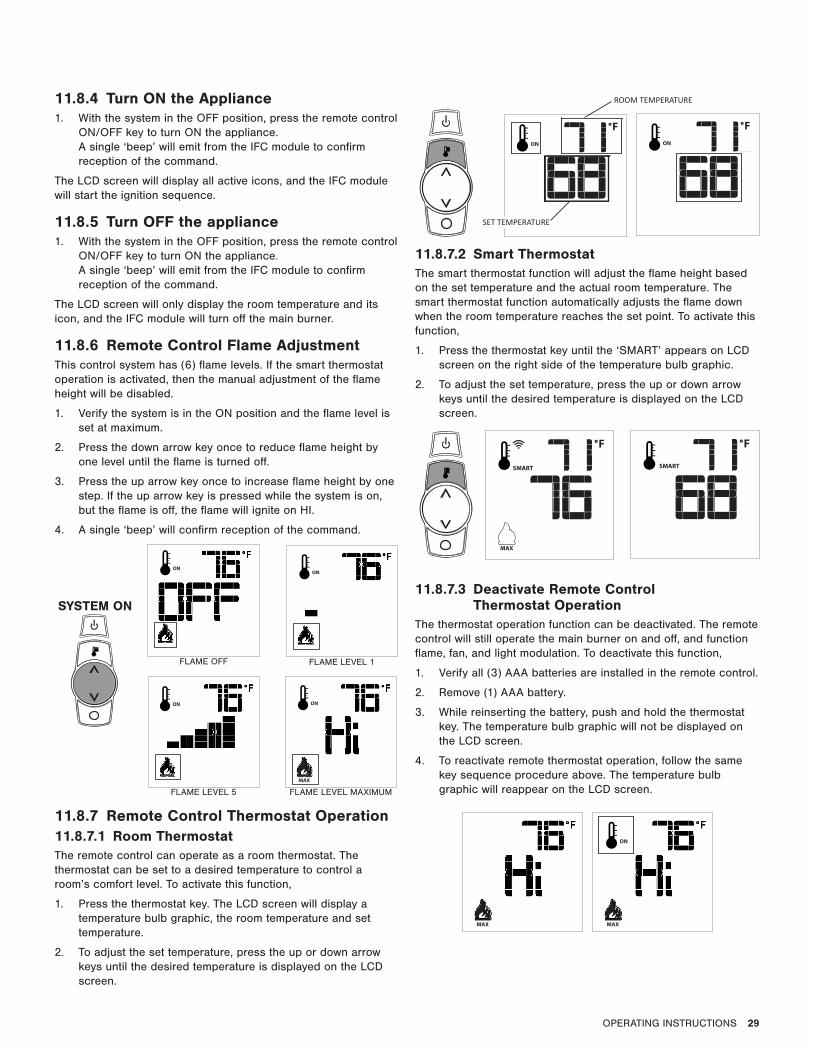
11.8.4 Turn ON the Appliance1. With the system in the OFF position, press the remote control
ON/OFF key to turn ON the appliance. A single ‘beep’ will emit from the IFC module to confirm reception of the command.
The LCD screen will display all active icons, and the IFC module will start the ignition sequence.
11.8.5 Turn OFF the appliance1. With the system in the OFF position, press the remote control
ON/OFF key to turn ON the appliance. A single ‘beep’ will emit from the IFC module to confirm reception of the command.
The LCD screen will only display the room temperature and its icon, and the IFC module will turn off the main burner.
11.8.6 Remote Control Flame AdjustmentThis control system has (6) flame levels. If the smart thermostat operation is activated, then the manual adjustment of the flame height will be disabled.
1. Verify the system is in the ON position and the flame level is set at maximum.
2. Press the down arrow key once to reduce flame height by one level until the flame is turned off.
3. Press the up arrow key once to increase flame height by one step. If the up arrow key is pressed while the system is on, but the flame is off, the flame will ignite on HI.
4. A single ‘beep’ will confirm reception of the command.
11.8.7 Remote Control Thermostat Operation11.8.7.1 Room ThermostatThe remote control can operate as a room thermostat. The thermostat can be set to a desired temperature to control a room’s comfort level. To activate this function,
1. Press the thermostat key. The LCD screen will display a temperature bulb graphic, the room temperature and set temperature.
2. To adjust the set temperature, press the up or down arrow keys until the desired temperature is displayed on the LCD screen.
11.8.7.2 Smart ThermostatThe smart thermostat function will adjust the flame height based on the set temperature and the actual room temperature. The smart thermostat function automatically adjusts the flame down when the room temperature reaches the set point. To activate this function,
1. Press the thermostat key until the ‘SMART’ appears on LCD screen on the right side of the temperature bulb graphic.
2. To adjust the set temperature, press the up or down arrow keys until the desired temperature is displayed on the LCD screen.
11.8.7.3 Deactivate Remote Control Thermostat Operation
The thermostat operation function can be deactivated. The remote control will still operate the main burner on and off, and function flame, fan, and light modulation. To deactivate this function,
1. Verify all (3) AAA batteries are installed in the remote control.
2. Remove (1) AAA battery.
3. While reinserting the battery, push and hold the thermostat key. The temperature bulb graphic will not be displayed on the LCD screen.
4. To reactivate remote thermostat operation, follow the same key sequence procedure above. The temperature bulb graphic will reappear on the LCD screen.
FLAME OFF FLAME LEVEL 1
FLAME LEVEL 5 FLAME LEVEL MAXIMUM
SYSTEM ON
SET TEMPERATURE
ROOM TEMPERATURE
30 OPERATING INSTRUCTIONS
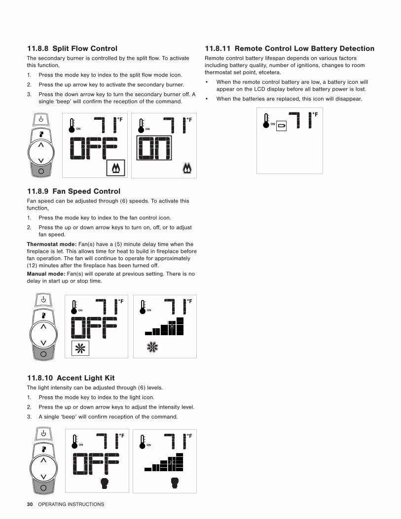
11.8.8 Split Flow ControlThe secondary burner is controlled by the split flow. To activate this function,
1. Press the mode key to index to the split flow mode icon.
2. Press the up arrow key to activate the secondary burner.
3. Press the down arrow key to turn the secondary burner off. A single ‘beep’ will confirm the reception of the command.
11.8.9 Fan Speed ControlFan speed can be adjusted through (6) speeds. To activate this function,
1. Press the mode key to index to the fan control icon.
2. Press the up or down arrow keys to turn on, off, or to adjust fan speed.
Thermostat mode: Fan(s) have a (5) minute delay time when the fireplace is let. This allows time for heat to build in fireplace before fan operation. The fan will continue to operate for approximately (12) minutes after the fireplace has been turned off.
Manual mode: Fan(s) will operate at previous setting. There is no delay in start up or stop time.
11.8.10 Accent Light Kit The light intensity can be adjusted through (6) levels.
1. Press the mode key to index to the light icon.
2. Press the up or down arrow keys to adjust the intensity level.
3. A single ‘beep’ will confirm reception of the command.
11.8.11 Remote Control Low Battery DetectionRemote control battery lifespan depends on various factors including battery quality, number of ignitions, changes to room thermostat set point, etcetera.
• When the remote control battery are low, a battery icon will appear on the LCD display before all battery power is lost.
• When the batteries are replaced, this icon will disappear.
ADJUSTMENT 31
12.0 ADJUSTMENT
12.1 Pressure TestingNOTE: The appliance and its appliance main gas valve must be disconnected from the gas supply piping system during any pressure testing of the system at test pressures in excess of ½ psi (3.5 kPa).
IMPORTANT: Pressure check taps for manifold (outgoing) and inlet (incoming) pressure have been incorporated into the valve. The pressure tap marked OUT measures outgoing pressure. The pressure tap marked IN measures incoming pressure.
12.1.1 Inlet Pressure TestNOTE: Make sure to apply these incoming pressure test with all other gas appliances on, or at full capacity in the house for proper pressure reading.
IMPORTANT: If the inlet pressure reading is too high or too low, contact the gas company. Only a qualified gas service technician should adjust incoming gas pressure.
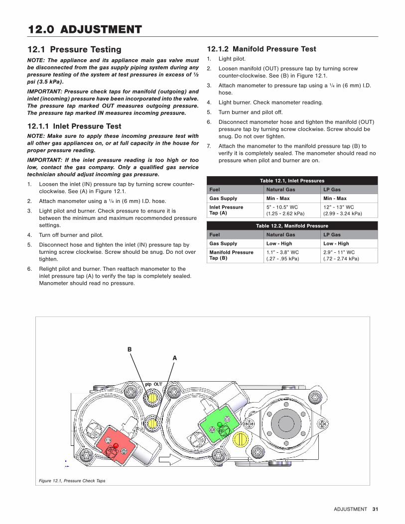
1. Loosen the inlet (IN) pressure tap by turning screw counter-clockwise. See (A) in Figure 12.1.
2. Attach manometer using a ¼ in (6 mm) I.D. hose.
3. Light pilot and burner. Check pressure to ensure it is between the minimum and maximum recommended pressure settings.
4. Turn off burner and pilot.
5. Disconnect hose and tighten the inlet (IN) pressure tap by turning screw clockwise. Screw should be snug. Do not over tighten.
6. Relight pilot and burner. Then reattach manometer to the inlet pressure tap (A) to verify the tap is completely sealed. Manometer should read no pressure.
12.1.2 Manifold Pressure Test1. Light pilot.
2. Loosen manifold (OUT) pressure tap by turning screw counter-clockwise. See (B) in Figure 12.1.
3. Attach manometer to pressure tap using a ¼ in (6 mm) I.D. hose.
4. Light burner. Check manometer reading.
5. Turn burner and pilot off.
6. Disconnect manometer hose and tighten the manifold (OUT) pressure tap by turning screw clockwise. Screw should be snug. Do not over tighten.
7. Attach the manometer to the manifold pressure tap (B) to verify it is completely sealed. The manometer should read no pressure when pilot and burner are on.
Table 12.1, Inlet Pressures
Fuel Natural Gas LP Gas
Gas Supply Min - Max Min - Max
Inlet Pressure Tap (A)
5” - 10.5” WC (1.25 - 2.62 kPa)
12” - 13” WC (2.99 - 3.24 kPa)
Table 12.2, Manifold Pressure
Fuel Natural Gas LP Gas
Gas Supply Low - High Low - High
Manifold Pressure Tap (B)
1.1” - 3.8” WC(.27 - .95 kPa)
2.9” - 11” WC(.72 - 2.74 kPa)
AB
Figure 12.1, Pressure Check Taps
32 ADJUSTMENT
12.2 Flame Appearance AdjustmentWARNING: To avoid property damage or personal injury, allow the fireplace ample time to cool before making any adjustments.
Burner flame appearance and characteristics are affected by altitude, fuel quality, venting configuration, and other factors. After installation, this appliance may need additional adjustments to achieve optimum flame appearance and visual aesthetics.
12.2.1 Burner Venturi WARNING: VENTURI ADJUSTMENT MUST BE DONE BY A QUALIFIED SERVICE TECHNICIAN.
NOTE: Burner venturi air shutter settings have been factory set.
When this appliance is first lit, the burner flames will appear blue. During the first 15 minutes of operation, flame appearance will gradually turn to the desired yellow appearance. If the flames remain blue, or become dark orange with evidence of sooting (black tips), adjustment of the air shutter opening may be necessary.
Regardless of venturi orientation, closing the air shutter will achieve a desired yellow flame, but may produce soot on the glass. Opening the air shutter will cause a short, blue flame that may lift off the burner.
12.2.1.1 Venturi Opening AdjustmentNOTE: If soot is present on the glass, check log positioning before adjusting the venturi. Logs must not block burner ports.
IMPORTANT: Slight adjustments to the venturi opening will create dramatic results. Adjust at slight increments until desired look is achieved. Follow Table 12.4 for guidance.
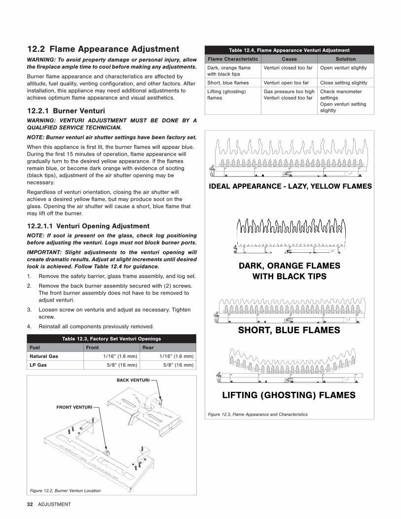
1. Remove the safety barrier, glass frame assembly, and log set.
2. Remove the back burner assembly secured with (2) screws. The front burner assembly does not have to be removed to adjust venturi.
3. Loosen screw on venturis and adjust as necessary. Tighten screw.
4. Reinstall all components previously removed.
Table 12.3, Factory Set Venturi Openings
Fuel Front Rear
Natural Gas 1/16” (1.6 mm) 1/16” (1.6 mm)
LP Gas 5/8” (16 mm) 5/8” (16 mm)
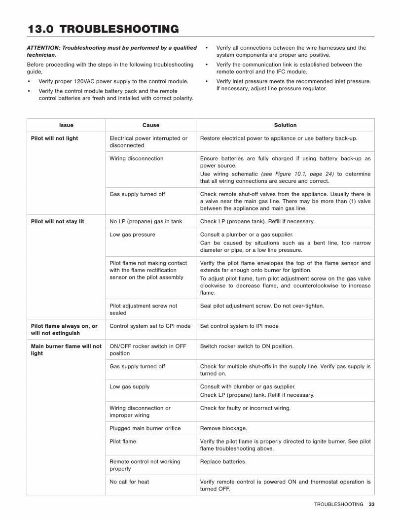
Table 12.4, Flame Appearance Venturi Adjustment
Flame Characteristic Cause Solution
Dark, orange flame with black tips
Venturi closed too far Open venturi slightly
Short, blue flames Venturi open too far Close setting slightly
Lifting (ghosting) flames
Gas pressure too high Venturi closed too far
Check manometer settings Open venturi setting slightly
IDEAL APPEARANCE - LAZY, YELLOW FLAMES
FRONT VENTURI
BACK VENTURI
Figure 12.2, Burner Venturi Location
Figure 12.3, Flame Appearance and Characteristics
SHORT, BLUE FLAMES
LIFTING (GHOSTING) FLAMES
DARK, ORANGE FLAMESWITH BLACK TIPS
TROUBLESHOOTING 33
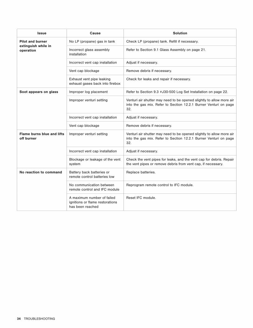
13.0 TROUBLESHOOTINGATTENTION: Troubleshooting must be performed by a qualified technician.
Before proceeding with the steps in the following troubleshooting guide,
• Verify proper 120VAC power supply to the control module.
• Verify the control module battery pack and the remote control batteries are fresh and installed with correct polarity.
• Verify all connections between the wire harnesses and the system components are proper and positive.
• Verify the communication link is established between the remote control and the IFC module.
• Verify inlet pressure meets the recommended inlet pressure. If necessary, adjust line pressure regulator.
Issue Cause Solution
Pilot will not light Electrical power interrupted or disconnected
Restore electrical power to appliance or use battery back-up.
Wiring disconnection Ensure batteries are fully charged if using battery back-up as power source.
Use wiring schematic (see Figure 10.1, page 24) to determine that all wiring connections are secure and correct.
Gas supply turned off Check remote shut-off valves from the appliance. Usually there is a valve near the main gas line. There may be more than (1) valve between the appliance and main gas line.
Pilot will not stay lit No LP (propane) gas in tank Check LP (propane tank). Refill if necessary.
Low gas pressure Consult a plumber or a gas supplier.
Can be caused by situations such as a bent line, too narrow diameter or pipe, or a low line pressure.
Pilot flame not making contact with the flame rectification sensor on the pilot assembly
Verify the pilot flame envelopes the top of the flame sensor and extends far enough onto burner for ignition.
To adjust pilot flame, turn pilot adjustment screw on the gas valve clockwise to decrease flame, and counterclockwise to increase flame.
Pilot adjustment screw not sealed
Seal pilot adjustment screw. Do not over-tighten.
Pilot flame always on, or will not extinguish
Control system set to CPI mode Set control system to IPI mode
Main burner flame will not light
ON/OFF rocker switch in OFF position
Switch rocker switch to ON position.
Gas supply turned off Check for multiple shut-offs in the supply line. Verify gas supply is turned on.
Low gas supply Consult with plumber or gas supplier.
Check LP (propane) tank. Refill if necessary.
Wiring disconnection or improper wiring
Check for faulty or incorrect wiring.
Plugged main burner orifice Remove blockage.
Pilot flame Verify the pilot flame is properly directed to ignite burner. See pilot flame troubleshooting above.
Remote control not working properly
Replace batteries.
No call for heat Verify remote control is powered ON and thermostat operation is turned OFF.
34 TROUBLESHOOTING
Issue Cause Solution
Pilot and burner extinguish while in operation
No LP (propane) gas in tank Check LP (propane) tank. Refill if necessary.
Incorrect glass assembly installation
Refer to Section 9.1 Glass Assembly on page 21.
Incorrect vent cap installation Adjust if necessary.
Vent cap blockage Remove debris if necessary.
Exhaust vent pipe leaking exhaust gases back into firebox
Check for leaks and repair if necessary.
Soot appears on glass Improper log placement Refer to Section 9.3 #J30-500 Log Set Installation on page 22.
Improper venturi setting Venturi air shutter may need to be opened slightly to allow more air into the gas mix. Refer to Section 12.2.1 Burner Venturi on page 32.
Incorrect vent cap installation Adjust if necessary.
Vent cap blockage Remove debris if necessary.
Flame burns blue and lifts off burner
Improper venturi setting Venturi air shutter may need to be opened slightly to allow more air into the gas mix. Refer to Section 12.2.1 Burner Venturi on page 32.
Incorrect vent cap installation Adjust if necessary.
Blockage or leakage of the vent system
Check the vent pipes for leaks, and the vent cap for debris. Repair the vent pipes or remove debris from vent cap, if necessary.
No reaction to command Battery back batteries or remote control batteries low
Replace batteries.
No communication between remote control and IFC module
Reprogram remote control to IFC module.
A maximum number of failed ignitions or flame restorations has been reached
Reset IFC module.

MAINTENANCE 35
14.0 MAINTENANCEATTENTION: Installation and repair should be done by a qualified service person. The appliance should be inspected before use and at least annually by a professional service person. More frequent cleaning might be required due to excessive lint from carpeting, bedding material, et cetera. It is imperative that control compartments, burners, and circulating air passageways of the appliance be kept clean.
WARNING: The appliance area must be kept clear and free from combustible materials, gasoline and other flammable vapors and liquids.
14.1 Burner and Pilot SystemRefer to Section 9.4 Control Board Removal and Installation on page 23 for instructions to access burner and pilot system.
Performed by: Qualified Service Person
Frequency: Annually
Action:
• Vacuum all components of the burner system.
• Visually check burner ports for blockage, especially near the pilot.
• Visually check pilot light and burner flame pattern when in operation. Flames should be steady, not lifting or floating. Refer to Figure 12.3, Flame Appearance and Characteristics on page 32.
14.2 FanCAUTION: Label all wires prior to disconnection when servicing controls. Wiring errors can cause improper and dangerous operation. Verify proper operation after servicing.
Performed by: Qualified Service Person
Frequency: Every 6 months
Action:
• Disconnect the fans from electrical current and vacuum.
• The bearings are sealed and require no oiling.
14.3 Vent SystemNOTE: If the vent-air intake system is disassembled for any reason, reinstall per instructions provided with installation. Section 6.0 Installation on page 15.
Performed by: Qualified Service Person
Frequency: Annually
Action:
• Examination of the vent system is required.
• The flow of combustion and ventilation air must not be obstructed.
14.4 Glass AssemblyCAUTION: Do not operate appliance with the glass assembly removed, cracked, or broken. Use protective gloves to handle any broken or damaged glass assembly components.
WARNING: Do not use substitute materials.
WARNING: Avoid striking or slamming glass assembly. Avoid abrasive cleaner. DO NOT clean glass while it is hot.
IMPORTANT: Any safety screen, guard, or barrier removed for servicing the appliance must be replaced prior to operating the appliance.
Performed by: Homeowner
Frequency: Annually
Action:
• Prepare a work area large enough to accommodate the glass assembly on a flat, stable surface.
• Remove safety screen and glass frame assembly.
• Clean glass with a soft cloth and a non-abrasive cleaner.
• Reinstall glass assembly and safety screen.
• Any safety screen, guard, or barrier removed for servicing the appliance must be replaced prior to operating the appliance.
Performed by: Qualified Service Person
Frequency: Annually
Action:
• Inspect the glass for cracks, scratches, and nicks.
• Verify the glass assembly is properly intact and not damaged.
• Replace the glass and the assembly #JOR-057T as necessary.
• Only Hussong Mfg. Co., Inc. will supply the replacement of glass assembly as a complete unit.
Figure 14.1, Burner and Pilot System
BACK BURNER ORIFICE
FRONT BURNER ORIFICE
PILOT FLAME
BURNER PORTS
36 REPLACEMENT PARTS LIST
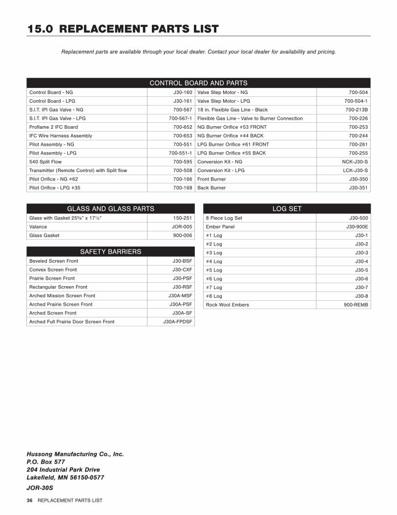
15.0 REPLACEMENT PARTS LIST
Replacement parts are available through your local dealer. Contact your local dealer for availability and pricing.
CONTROL BOARD AND PARTSControl Board - NG J30-160 Valve Step Motor - NG 700-504
Control Board - LPG J30-161 Valve Step Motor - LPG 700-504-1
S.I.T. IPI Gas Valve - NG 700-567 18 in. Flexible Gas Line - Black 700-213B
S.I.T. IPI Gas Valve - LPG 700-567-1 Flexible Gas Line - Valve to Burner Connection 700-226
Proflame 2 IFC Board 700-652 NG Burner Orifice #53 FRONT 700-253
IFC Wire Harness Assembly 700-653 NG Burner Orifice #44 BACK 700-244
Pilot Assembly - NG 700-551 LPG Burner Orifice #61 FRONT 700-261
Pilot Assembly - LPG 700-551-1 LPG Burner Orifice #55 BACK 700-255
540 Split Flow 700-595 Conversion Kit - NG NCK-J30-S
Transmitter (Remote Control) with Split flow 700-508 Conversion Kit - LPG LCK-J30-S
Pilot Orifice - NG #62 700-166 Front Burner J30-350
Pilot Orifice - LPG #35 700-168 Back Burner J30-351
LOG SET8 Piece Log Set J30-500
Ember Panel J30-900E
#1 Log J30-1
#2 Log J30-2
#3 Log J30-3
#4 Log J30-4
#5 Log J30-5
#6 Log J30-6
#7 Log J30-7
#8 Log J30-8
Rock Wool Embers 900-REMB
GLASS AND GLASS PARTSGlass with Gasket 255/8” x 17½” 150-251
Valance JOR-005
Glass Gasket 900-006
Hussong Manufacturing Co., Inc. P.O. Box 577 204 Industrial Park Drive Lakefield, MN 56150-0577
JOR-30S
SAFETY BARRIERSBeveled Screen Front J30-BSF
Convex Screen Front J30-CXF
Prairie Screen Front J30-PSF
Rectangular Screen Front J30-RSF
Arched Mission Screen Front J30A-MSF
Arched Prairie Screen Front J30A-PSF
Arched Screen Front J30A-SF
Arched Full Prairie Door Screen Front J30A-FPDSF
LIMITED WARRANTY 37
LIMITED WARRANTY
Kozy Heat Limited 10 Year WarrantyThis limited 10 Year Warranty will not become effective until the Warranty Registration Form has been completed and mailed to Hussong Manufacturing Co., Inc., P.O. Box 577, Lakefield, MN 56150. This registration form must be received within 30 days of installation. Failure to do so may result in delayed warranty coverage and submission of proof of purchase will be required.
Hussong Manufacturing Co., Inc. warranties to the original purchaser of this Kozy Heat Fireplace, that it is free of defects in materials and workmanship at the time of manufacture.
Subject to the following conditions & requirements, Hussong Manufacturing Co., Inc. extends the following limited warranty under normal use and service, with respect to the Kozy Heat line of gas burning fireplaces.
Year 1Subject to the conditions & requirements listed below, within the first year from date of purchase, Hussong Manufacturing Co., Inc. shall, at its discretion, replace or repair any such defect in material or workmanship, at Hussong Manufacturing Co., Inc.’s expense, including reasonable labor costs to repair or replace the defective component, if a factory pre-authorization is given for the repair.
Years 2 through 10Subject to the conditions & requirements listed below, beginning with the first day of the second year and continuing through the tenth year, Hussong Manufacturing Co., Inc., will at its discretion, provide repair or replacement parts at current list prices for any defect in material or workmanship of components, including optional components and accessories (if available). Hussong Manufacturing Co., Inc. shall not be responsible for any installation, labor, transportation of other indirect costs.
Limitation of LiabilityTo make a claim under this warranty, the purchaser must first contact the dealer/installer from whom the fireplace was purchased.
This limited warranty will be void if the fireplace is not installed by a qualified installer and according to the installation instructions. Use of unauthorized components will make this warranty null and void.
This limited warranty also is void if the fireplace is not operated, at all times, according to the operating instructions furnished.
This warranty is limited to defects in material and workmanship. It does not apply to any product that has been subject to negligence, misapplication, improper installation.
No person is authorized to extend the time of this warranty or to accept on Hussong Manufacturing Co., Inc.’s behalf any additional obligation of liability connected with the unit.
It is expressly agreed and understood that this warranty is Hussong Manufacturing Co., Inc.’s sole obligation and purchaser’s exclusive remedy for defective fireplace equipment. Hussong Manufacturing Co., Inc. shall not be liable for any consequential, incidental or contingent damages whatsoever. The foregoing warranty is exclusive and in lieu of all other expressed warranties. Hussong Manufacturing Co., Inc. shall not be held to implied warranties or merchantability and fitness for a particular purpose. This warranty replaces all previous warranty policies.
Some states do not allow the exclusion or limitation of incidental or consequential damages or limitations on how long an implied warranty lasts, so the above limitations or exclusions may not apply to you. This warranty gives you specific legal rights and you may also have other rights which vary from state to state.
Hussong Manufacturing Co., Inc. reserves the right to make changes at any time, without notice, in design, material, specifications and prices. Hussong Manufacturing Co., Inc. reserves the right to discontinue models and products.
December 2014
Warranty Conditions and Requirements1. You are the original purchaser. This warranty is not transferable.
2. Installation of the fireplace is performed by a qualified installer.
3. Installation and operation must comply with installation and operation instructions.
4. Paint and glass gaskets are covered for 30 days from date of purchase.
5. Remote controls and all optional accessories are covered for 1 year from date of purchase.
6. This warranty does not offer coverage for Light Bulbs, Batteries or Fuses (whether factory, dealer or installer supplied). This includes any damage stemming from either component’s nonuse.
7. Components broken, (including glass panels), during shipping, careless handling of components, or defects resulting from improper installation, misuse of the fireplace and components are not covered under this warranty.
8. This warranty does not cover any part of the fireplace or any components which have been exposed to or submerged underwater.
9. Hussong Manufacturing Co., Inc. must be notified by the dealer the fireplace was purchased from or a qualified installer/service technician of the defect.
10. Annual service of the fireplace as required in the installation manual, is performed by a qualified installer/service technician. (Copies of such service records may be required to claim a warranty).
11. All previous warranty/service has been performed by a qualified installer or service technician. (Copies of such service records may be required to claim a warranty).

LIFETIME WARRANTY 39
LIFETIME WARRANTYLIFETIME WARRANTY COVERAGE WILL BE EXTENDED AS DESCRIBED BELOW PROVIDED ALL WARRANTY CONDITIONS AND
REQUIREMENTS ARE MET AS OUTLINED IN THE 10 YEAR LIMITED WARRANTY POLICY.
Lifetime Warranty CoverageLIFETIME WARRANTY IS EXTENDED AS FOLLOWS: Hussong Manufacturing Co., Inc. warranties to the original purchaser that the firebox, heat exchanger, fiber logs, burner tube and glass panel of this Kozy Heat Fireplace will not be defective in material or workmanship under normal use and service for as long as you own this product. If any of these components fail due to defects in material and workmanship under normal use and service, Hussong Manufacturing, Co., Inc. will, at its sole discretion, repair or replace the defective component. This LIFETIME WARRANTY does not cover any installation, labor, transportation or other indirect cost arising from defective components.
Limitation of LiabilityThis Lifetime Warranty will be void if the fireplace is not installed by a qualified installer and according to the installation instructions. Use of unauthorized components will make this warranty null and void. This Lifetime Warranty also is void if the fireplace is not operated, at all times, according to the operating instructions furnished. This warranty is limited to defects in material and workmanship of components specified. It does not apply to any product that has been subject to negligence, misapplication, improper installation.
No person is authorized to extend the time of this Lifetime Warranty or to accept on Hussong Manufacturing Co., Inc.’s behalf any additional obligation of liability connected with the unit.
Hussong Manufacturing Co., Inc. may fully discharge all obligations with respect to this Lifetime Warranty by refunding the wholesale price of the defective component(s).
It is expressly agreed and understood that this Lifetime Warranty is Hussong Manufacturing Co., Inc.’s sole obligation and original purchaser’s exclusive remedy for defective fireplace equipment. Hussong Manufacturing Co., Inc. shall not be liable for any consequential, incidental or contingent damages whatsoever other than those incurred by Hussong Manufacturing Co., Inc. to repair or replace the defective component. The foregoing warranty is exclusive and in lieu of all other expressed warranties. Hussong Manufacturing Co., Inc. shall not be held to implied warranties, including but not limited to the implied warranties or merchantability and fitness for a particular purpose. This lifetime warranty replace all previous lifetime warranty policies.
Hussong Manufacturing Co., Inc. reserves the right to make changes at any time, without notice, in design, material, specifications and prices. Hussong Manufacturing Co., Inc. reserves the right to discontinue models and products.
To activate this Lifetime Warranty coverage, this registration card must be completed and mailed with your completed 10 Year Limited Warranty form within 30 days of installation to the following address:
Hussong Manufacturing Co., Inc. P.O. Box 577 204 Industrial Park Drive Lakefield, MN 56150-0577
September 2011
CUT ALONG DOTTED LINE
PURCHASER NAME: _______________________________
ADDRESS: ________________________________________
__________________________________________________
TELEPHONE: _____________________________________
__________________________________________________
INSTALLER NAME: _________________________________
ADDRESS: ________________________________________
__________________________________________________
TELEPHONE: _____________________________________
__________________________________________________
INSTALLATION DATE: ______________________________
MODEL NUMBER: _________________________________
SERIAL NUMBER: _________________________________
HUSSONG MANUFACTURING CO., INC.