Embed Size (px)
Citation preview
HSE & LIFTING
RC Minton, F.E. Fragachánand Q Guo, M-I SWACO
A UNIQUE SUBSURFACE cuttingsreinjection (CRI) assurance service,comprising a team of geomechanics andpetroleum engineering specialists, issuccessfully providing premium integrat-ed solid and liquid waste injection servic-es for operators worldwide.
Services contained within the integratedpackage include front-end engineeringand feasibility studies, project-specificinjection procedures, custom-designedsubsurface injection equipment, specifi-cally trained subsurface injection engi-neers, monitoring and evaluation ofongoing operations.
A key objective of the integrated group ismitigating the risks and potential long-term liabilities associated with subsur-face waste injection and disposal. Theall-inclusive and one-of-a-kind servicehas been employed in high-profile proj-ects off Sakhalin Island, Mexico’s Bay ofCampeche, the Caspian Sea and else-where.
T H E C R I P R O C E S S
When oil-based drilling fluids are utilizedin the drilling operation, the cuttings arecovered with a residual layer of the oilyfluid and have to be disposed of in such away as to avoid environmental damage.In offshore CRI operations, these cuttingsare most commonly mixed with sea waterand energized via some form of mixingenergy, such that the mixture forms sta-ble viscous slurries that are pumped intoa dedicated disposal well, or through theannulus between casing strings.
In most cases, the injection program pro-ceeds without serious mishap. However,there are many instances of the annuli orcasings becoming blocked and of block-ages of the injection perforations. Addi-tionally, there are reported cases of slur-ry migrating through natural fractures,or poorly cemented sections of the well,back to the surface and, cases of the frac-tures propagating back to the sea bedwith consequential release of the slurry.
These failures have resulted in signifi-cant environmental damage and havebeen costly in terms of remediation of theinjection well, clean-up programs and, insome cases, have necessitated the
drilling of new injection wells. Operatorshave been fined for their failure to con-trol the CRI process, and, on occasion,injection permits have been revoked,impacting the whole drilling program.
It is evident that a more thorough engi-neering and assurance approach is
required. Inherent risks in the processneed to be identified and pro-activelymanaged. Additionally, continuous moni-toring of the CRI process needs to beimproved such that any developing fail-ures can be identified at an early stageand mitigation steps taken.
CRI aims to reduce reinjection risk, liability
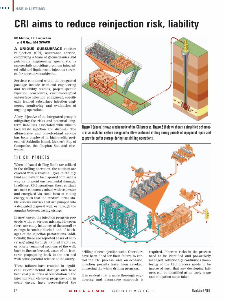
FFiigguurree 11 (above) shows a schematic of the CRI process. FFiigguurree 22 (below) shows a simplified schemat-ic of an installed system designed to allow continued drilling during periods of equipment repair andto provide buffer storage during fast drilling operations.
52 D R I L L I N G C O N T R A C T O R March/April 2006
jan06-jimredden.qxp 2/21/2006 1:10 PM Page 52
M I T I G A T I N G S U R F A C E R I S K S
Delays to the drilling operation can becaused by mechanical failures of the CRIequipment or because of undercapacity.To obviate these risks, it is important tode-couple the drilling and CRI opera-tions. This can be achieved through theinstallation of additional processingcapacity. However, with space at a premi-um offshore, this is often impractical.While preventative maintenance reducesthe risk of failure, it does not address theundercapacity issue during rapid drillingphases. However, recent advances in thepneumatic collection, transportation andstorage of oily cuttings mean that equip-ment failure issues and undercapacitylimitations can now be overcome.
Cuttings and the solids from the cen-trifuges can feed directly to the CRI unit,as usual. In the event of failure or excesscuttings production, part or all of the vol-ume can be pneumatically transferred tothe storage tanks. Once the repair iscomplete or the cuttings generation rateslows down, cuttings can then be trans-ferred from the storage tanks back to theCRI unit for processing. This effectivelyde-couples the drilling activity from theCRI process, allowing for optimumdrilling performance.
R E D U C I N G T H E R I S K S
A CRI disposal solution must be support-ed by a sound engineering assessment.Simulating different “what if” scenariosprovides a probability window of results,that, if adequately managed, will mini-mize the risks of failure.
For instance, continuous monitoring ofslurry quality and, more importantly,formation pressure response to injection,in conjunction with special diagnosticplots, has proven to be invaluable tools tomitigate the associated risk.
The “know how” infused in these pres-sure responses is not trivial and requiresa continuous analysis to every batchinjected. In fact, from well to well, eachset of conditions represents a new set of“in-situ” domain parameters requiringcharacterization and engineering evalu-ation. Extrapolations of local best prac-tices without specific understanding in-situ geomechanics and reservoir condi-tions have major ingredients of environ-mental and financial fiascos.
It must be noted that these evaluationsare performed based on data gathered,which is as good and sound as its quality.
The high visibility of legislations world-wide has driven the need to enhance thequality of these data. In fact, currently itis common to encounter projects withbottomhole pressures, opening up for ahuge understanding and interpretationin pressure decline “anomaly” — behav-iors that have been so labeled because asound engineering understanding of itsbehavior is pending.
This is the challenge to the engineeringrisk assessment. The evaluation andinterpretation of these pressure analysis
signatures, reflecting informationregarding not only the geometry, spatialdistribution of the injected waste, andcontainment, but of the effectiveness ofthe injection and, even more important,about its endurance.
A L L E V I A T I N G P L U G G I N G
Plugging of the tubing, annulus or perfo-rations is a result of solids settling fromthe slurry, normally during shut-in peri-ods when the slurry is static. The rate ofsettlement is a function of particle size,
HSE & LIFTING
March/April 2006 D R I L L I N G C O N T R A C T O R 53
jan06-jimredden.qxp 2/21/2006 1:10 PM Page 53
the low shear rate viscosity of the fluidand time. When an injection wellbecomes plugged from particle settling,attempts have to be made to clear theblockage, re-perforate the tubing at ashallower depth or move to anotherinjection well. All of these steps aretime–consuming and costly, often impact-ing the normal drilling operation. In theworst case, where an alternative injec-tion well is not available, this may evenentail the drilling of a completely newwell, resulting in a delay to the overallproject and adding significant costs.
Quality control of the slurry is normallyachieved through measurement of thefluid density and funnel viscosity. Howev-er, the slurry is thixotropic, or shear thin-ning. Hence, funnel viscosity is only rela-tive, not one that can be used to modelthe suspension characteristics of thefluid.
In order to fully characterize the slurry’sviscosity, a viscosity profile at variousshear rates and temperatures isrequired. That can be used, within asolids transport model, to predict therate at which the particles will settle.This in turn will dictate the safe periodfor the slurry to remain static and,hence, the point at which displacement ofthe slurry out of the tubing or annulushas to be done.
Such data can be used to develop a slur-ry design specification and a pumpingprocedure aimed at minimizing the riskof plugging. In the optimum case, a bot-tomhole pressure sensor is installed. Thechanging pressure readings, under staticconditions, give direct indications ofdeveloping settling problems, which canthen be pro-actively managed.
F R A C T U R E P R O P A G A T I O N S
In almost all cases, a CRI program is pre-ceded by a fracture-modeling study usingnumerical predictive models of variousdegrees of sophistication. These indicatethe likely propagation behavior of thefracture relative to the injected volume.However, even the most sophisticated 3-D model predictions are inaccuratebecause of the assumptions made in cre-ating the model.
At the planning stage, the rock proper-ties are seldom well understood; theexact lithological sequence is notknown, and assumptions have to bemade for a wide variety of the inputparameters. This is particularly truewith respect to physical rock proper-
ties. In order to overcome these limita-tions, a probabilistic approach needs tobe taken, where multiple models run isconducted using the range of values foreach variable.
Once the injection well has been drilledand logged, the measured rock proper-ties and an exact lithology sequencecan be input into the model, thusimproving its accuracy. Then, the firstinjection sequence, with its informationregarding the cycle of injection pres-sure for particular pumping rates, slur-ry densities and viscosities, validatesthe model. This cycle of monitoring,model update and validation then needsto be repeated at intervals during theslurry injection project, so that the
model can be continually refined andthe projected ranges of capacity, frac-ture growth and pressure development,narrowed. This provides the assurancethat the formation pressure response isdeveloping as predicted.
Deviations from the modeled pressuretrends during the injection phases thenprovide early warning signals of unexpect-ed fracture development. Both pressureresponses during injection and duringdecline analysis must provide an insight toevaluate the likely causes of the pressure“anomalies” and steps be taken to miti-gate the consequences of the unintendeddevelopment and/or provide the engineer-ing needs to get back on track. �
54 D R I L L I N G C O N T R A C T O R March/April 2006
HSE & LIFTING
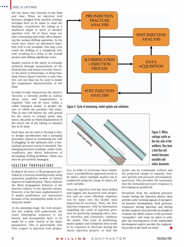
Figure 4: Cycle of monitoring, model update and validation.
Figure 3: Whencuttings settle onthe low side of thewellbore, they forma bed that ulti-mately becomesunstable andslides downhole.
jan06-jimredden.qxp 2/21/2006 1:11 PM Page 54