Embed Size (px)
Citation preview
I
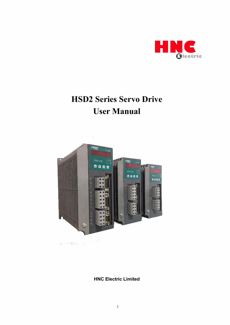
HSD2 Series Servo DriveUser Manual
HNC Electric Limited
HSD2 Series AC Servo Drive
II
Thank you for purchasing our HSD2 AC servo drives.This manual provides the related information about product installation, wiring,inspection and operation of our AC servo drive. Before using the product, please readthrough this manual carefully in order to ensure the correct use of the product.This manual includes:
Installation of AC servo drivesConfiguration and wiringParameter settingsControl functions and adjusting methods of AC servo drivesTrial run stepsTroubleshooting
This manual is intended for the personnel with the following qualifications:Installation or wiring personnelOperating or programming personnelTroubleshooting personnel
Important Precautions
Before using the product, please read this user manual thoroughly to ensure correctuse and place this manual in a safe place for a quick reference whenever is needed. Inaddition, please pay your attention to the following precautions accordingly:
No water, corrosive and inflammable gas are allowed in the installationenvironment.
Ensure that the drive is correctly connected to a ground. The grounding methodmust comply with the electrical standard of the country.
Do not connect a commercial power supply to the U,V,W terminals of drives, itmay damage the drive.
Do not disconnect servo drive, motor or change the wiring when power is ONDo not touch the heat sink of the drive before connecting to the power and
operation.If you have any inquiries, please contact your local distributor or our customer
service center.

HSD2 Series AC Servo Drive
III
Preface
Please read and follow the following NOTES before using the product:
1. HSD2 series driver is designed to apply with AC 220V power input. Do notconnect this product with AC 380V power, it’s possible to damage the drive orcause personnel injury.
2. Please refer to this user manual, set the correct motor parameters PA1,so as toensure proper parameters match between servo drive and motor.
3. Do not turn the power on and off too often, if continuous power on and off isneeded, please add break resistor. Please follow the user manual or contact ourtechnical support, use the correct break resistor for the driver.
4. Please set the right Electronic Gear Ratio parameter PA12, PA13.
5. Please set the right pulse command input parameter PA14.
6. When you finished the parameters setting of PA1,PA14, PA35, please re-powerthe drive to activate and save the modified settings.
7. Please use stranded wires and multi-core shielded-pair wires for making theencoder cable. The total length should not exceed 15meters.
8. Please use shielded wires to make control cable as well, and the max length ofthe control cable is 15meters, otherwise it may cause pulse lose.

HSD2 Series AC Servo Drive
IV
Safety PrecautionsInstallation
◆It is not allowed to expose the product with the environment whichcontains water, corrosive gas, inflammable gas, etc.Otherwise it may resultin electric shock,fire or personal injury.◆Do not apply the product to the environment of direct sunlight,dust,saltand metal powder,etc.◆It is prohibited to apply this product to the place which contains oil andpharmaceuticals, etc.
Wiring◆Please connect the ground terminals to a class-3 ground system (Under100 Ω),poor grounding may result in electric shock or fire.◆The HSD2 series AC servo drive is applicable for AC 220V single-phaseor three-phase power. Please do not connect the product to AC 380V power.Otherwise it’s may lead to possible drive damage..◆ Do not connect the three-phase source to the output terminal U, Vand W. Or it is possible to cause personnel injury or fire, or damage thedrive.◆Please tighten the screws of the power, wire terminals & connectors ofthe motor and drive, otherwise it may result in damage, fire or personnelinjury.◆In order to prevent any danger, it is strongly recommended to follow thespecifications outlined in this manual when wiring.
Operation◆Before the operation, please change the parameter setting valueaccording to the requirement, if it is not properly adjusted to the correctsetting value, it may cause equipment out of control, or lead to malfunctionof the machine.◆Do not touch or approach any rotating parts (e.g. Heat sink) duringoperation, it may cause serious personnel injury.◆Do not remove /disconnect the operation panel while the drive is
HSD2 Series AC Servo Drive
V
connected to the power supply, otherwise, it is possible to cause electricshock.◆Do not disassemble the servo drive as this may cause electric shock orpersonnel injury.◆Do not connect or disconnect wires or connectors while power is on,otherwise it may cause electric shock or personnel injury.
◆The high voltage may still remain in the servo drive when the power is off,
please wait for at least 10 minutes (after power is off) before touching or
performing any inspections.
HSD2 Series AC Servo Drive
VI
Contents
CHAPTER 1 PRODUCT DESCRIPTION....................................................................................................1
1.1 HSD2 SERIES SERVO DRIVES....................................................................................................................11.2 APPEARANCE................................................................................................................................................ 11.3 EXPLANATION OF EACH POWER TERMINALS............................................................................................ 2
1.3.1 P / D / C terminals.............................................................................................................................. 21.3.2 R / S / T terminals...............................................................................................................................21.3.3 R / T terminals..................................................................................................................................... 31.3.4 U / V / W / PE terminals.....................................................................................................................31.3.5 CN1 connector.................................................................................................................................... 31.3.6 CN2 connector.................................................................................................................................... 31.3.7 CN3 connector.................................................................................................................................... 3
CHAPTER 2 INSTALLATION & WIRING.....................................................................................................4
2.1 PRE-CHECK BEFORE INSTALLATION............................................................................................................42.2 PRODUCT SIZE............................................................................................................................................. 52.3 SIZE DATA FOR INSTALLATION.................................................................................................................... 52.4 INSTALLATION ENVIRONMENT......................................................................................................................62.5 INSTALLATION PROCEDURE & MINIMUM CLEARANCES............................................................................. 72.6 CONNECTION TERMINALS............................................................................................................................ 9
CHAPTER 3 SIGNAL INTERFACE AND WIRING..................................................................................... 12
3.1 OVERVIEW...................................................................................................................................................123.2 CN1 ENCODER CONNECTOR.................................................................................................................... 12
3.2.1 CN1 connector view and layout..................................................................................................... 123.2.2 Signal definition for CN1..................................................................................................................13
3.3 CN2 CONNECTOR VIEW AND LAYOUT......................................................................................................133.4 SIGNAL DEFINITION OF CN2 CONNECTOR...............................................................................................143.5 I/O INTERFACE............................................................................................................................................16
3.5.1 Digital signal input interface............................................................................................................163.5.2 Digital signal output interface......................................................................................................... 163.5.3 Pulse command input interface......................................................................................................173.5.4 Analog signal input interface.......................................................................................................... 173.5.5 Encoder signal output interface......................................................................................................183.5.6 Encoder open-collector Z-pulse output interface........................................................................ 203.5.7 Encoder feedback signal input interface...................................................................................... 20
3.6 STANDARD CONNECTION EXAMPLE..........................................................................................................213.6.1 Position control mode...................................................................................................................... 213.6.2 Speed / torque control mode.......................................................................................................... 22
CHAPTER 4 PANEL DISPLAY & OPERATION......................................................................................... 23
4.1 PANEL DESCRIPTION..................................................................................................................................23
HSD2 Series AC Servo Drive
VII
4.2 MAIN MENU.................................................................................................................................................244.3 MONITORING DISPLAY(DP--)............................................................................................................... 254.4 PARAMETER SETTING(PA--)................................................................................................................ 254.5 PARAMETER MANAGEMENT(EE--).......................................................................................................264.6 SPEED TRIAL RUN WITHOUT LOAD(SR--)...........................................................................................274.7 JOG TRIAL RUN WITHOUT LOAD(JR--).............................................................................................. 274.8 ANALOG ZERO-OFFSET ADJUSTMENT (AU)............................................................................................. 28
CHAPTER 5 TRIAL RUN AND TUNING....................................................................................................... 29
5.1 INSPECTION WITHOUT LOAD..................................................................................................................... 295.1.1 Apply power to the drive..................................................................................................................305.1.2 JOG trial run without load................................................................................................................305.1.3 Speed trial run without load............................................................................................................ 31
5.2 POSITION CONTROL MODE........................................................................................................................335.2.1 Simple position control system.......................................................................................................335.2.2 Parameters for the position control............................................................................................... 355.2.3 Electronic gear ratio......................................................................................................................... 375.2.4 Position control gain.........................................................................................................................39
5.3 GAIN ADJUSTMENT.....................................................................................................................................405.3.1 Steps for gain adjustment............................................................................................................... 415.3.2 Gain adjustment for speed control loop........................................................................................415.3.3 Gain adjustment for position control loop.....................................................................................42
5.4 ELECTROMAGNETIC BRAKE....................................................................................................................... 425.4.1 Parameters of electromagnetic brake........................................................................................... 435.4.2 Wiring of electromagnetic brake.................................................................................................... 44
5.5 TIMING.........................................................................................................................................................455.5.1 Timing for power supply.................................................................................................................. 455.5.2 Timing for enable operation............................................................................................................ 465.5.3 Servo enable & servo alarm flowchart.......................................................................................... 47
5.6 START & STOP........................................................................................................................................... 485.6.1 On-off frequency and load inertia.................................................................................................. 495.6.2 Adjustment Method.......................................................................................................................... 49
CHAPTER 6 PARAMETERS........................................................................................................................... 50
6.1 PARAMETER SUMMARY..............................................................................................................................506.2 DETAILED PARAMETER DESCRIPTION......................................................................................................54
CHAPTER 7 MOTOR TYPE MATCHING...................................................................................................66
7.1 MOTOR TYPE LIST FOR HSD2-020.........................................................................................................677.2 MOTOR TYPE LIST FOR HSD2-030.........................................................................................................687.3 MOTOR TYPE LIST FOR HSD2-050.........................................................................................................697.4 MOTOR TYPE LIST FOR HSD2-065.........................................................................................................707.5 MOTOR TYPE LIST FOR HSD2-030A......................................................................................................71

HSD2 Series AC Servo Drive
VIII
CHAPTER 8 ALARM, PROTECTION FUNCTION & TROUBLESHOOTING.....................................72
8.1 ALARM CODE CHECK LIST........................................................................................................................728.2 POTENTIAL CAUSE AND CORRECTIVE ACTIONS......................................................................................74
CHAPTER 9 CONNECTION TO MOTOR.................................................................................................. 79
CHAPTER 10 SYSTEM CONNECTION..................................................................................................... 80
HSD2 Series AC Servo Drive
1
Chapter 1 Product Description
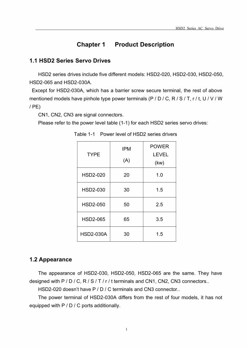
1.1 HSD2 Series Servo Drives
HSD2 series drives include five different models: HSD2-020, HSD2-030, HSD2-050,HSD2-065 and HSD2-030A.Except for HSD2-030A, which has a barrier screw secure terminal, the rest of above
mentioned models have pinhole type power terminals (P / D / C, R / S / T, r / t, U / V / W/ PE)
CN1, CN2, CN3 are signal connectors.Please refer to the power level table (1-1) for each HSD2 series servo drives:
Table 1-1 Power level of HSD2 series drivers
TYPEIPM
(A)
POWERLEVEL(kw)
HSD2-020 20 1.0
HSD2-030 30 1.5
HSD2-050 50 2.5
HSD2-065 65 3.5
HSD2-030A 30 1.5
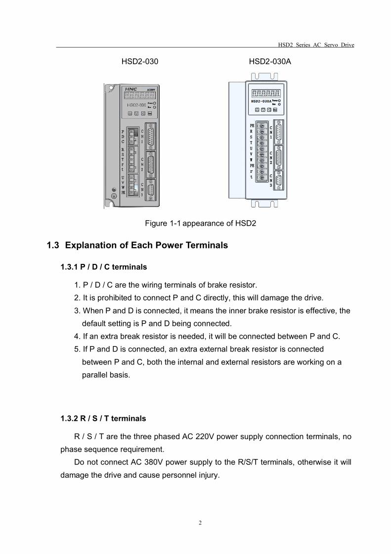
1.2 Appearance
The appearance of HSD2-030, HSD2-050, HSD2-065 are the same. They havedesigned with P / D / C, R / S / T / r / t terminals and CN1, CN2, CN3 connectors..
HSD2-020 doesn’t have P / D / C terminals and CN3 connector..The power terminal of HSD2-030A differs from the rest of four models, it has not
equipped with P / D / C ports additionally.
HSD2 Series AC Servo Drive
2
HSD2-030 HSD2-030A
Figure 1-1 appearance of HSD2
1.3 Explanation of Each Power Terminals
1.3.1 P / D / C terminals
1. P / D / C are the wiring terminals of brake resistor.2. It is prohibited to connect P and C directly, this will damage the drive.3. When P and D is connected, it means the inner brake resistor is effective, the
default setting is P and D being connected.4. If an extra break resistor is needed, it will be connected between P and C.5. If P and D is connected, an extra external break resistor is connected
between P and C, both the internal and external resistors are working on aparallel basis.
1.3.2 R / S / T terminals
R / S / T are the three phased AC 220V power supply connection terminals, nophase sequence requirement.
Do not connect AC 380V power supply to the R/S/T terminals, otherwise it willdamage the drive and cause personnel injury.
HSD2 Series AC Servo Drive
3
1.3.3 R / T terminals
R/T are the power supply terminals for the control system of the servo drive, AC220V power supply is required in this case.
It will cause damages to the drive if you connect AC 380V power supply tothese two terminals.
1.3.4 U / V / W / PE terminals
U / V / W / PE are the power output terminals of the drive, they can beconnected to the corresponding ports of the servo motor.
The power cable is generally supplied by the manufacturer, if you need to makethe power cable by yourself, please make sure you use the right shielded wire andensure a correct connection of U / V / W / PE terminals to avoid loosing control ofthe drive.
Please follow up the instructions from table 2-3 and table 2-4.
1.3.5 CN1 connector
CN1 is the encoder signal interface, it’s used to receive position signals fromservo motor.
Only incremental encoder is applicable to our HSD2 series servo drive.Incremental encoder has 6 signals: U V W A B Z, adopting differential output for
each signal. The encoder resolution is 2500 PPR, please find the detaileddefinitions from table 3-1.
1.3.6 CN2 connector
CN2 is the control signal interface, detailed definitions, please refer to table 3-2.
1.3.7 CN3 connector
CN3 is the communication interface, it is a reserved port at the time being.

HSD2 Series AC Servo Drive
4
Chapter 2 Installation & Wiring
In this chapter, you will find the related information and cautions for storage,installation environment, wiring of HSD2 series servo drive.
1. If the driver is severely damaged during transportation, please do not power onthe drive, contact the supplier for further actions.
2. Do not connect AC 380V power supply to R/S/T terminals.3. Please ensure PE port is properly connected and earthed.
2.1 Pre-check Before Installation
After receiving the AC servo drive, please check for the following:
Ensure that the product is what you have ordered.Please check the nameplate to identify if the product you received is what you’ve
ordered from the supplier. (You can refer to Section 1.1 and 1.3 for more details aboutthe model explanation).
Check the appearance to see if there is any damage.Please inspect the product carefully to see whether or not there is any damage
during transportation or shipping. Turn the motor shaft by hand, a smooth rotationindicates a good motor. However, a servo motor with an electromagnetic brake can notbe rotated manually.
Check the screwsEnsure that all necessary screws are tightened and secured.If any items are damaged, please inform the distributor whom you purchased the
product from or your local sales representative.
HSD2 Series AC Servo Drive
5
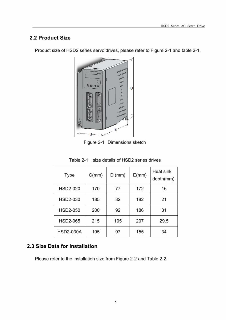
2.2 Product Size
Product size of HSD2 series servo drives, please refer to Figure 2-1 and table 2-1.
Figure 2-1 Dimensions sketch
Table 2-1 size details of HSD2 series drives
Type C(mm) D (mm) E(mm)Heat sinkdepth(mm)
HSD2-020 170 77 172 16
HSD2-030 185 82 182 21
HSD2-050 200 92 186 31
HSD2-065 215 105 207 29.5
HSD2-030A 195 97 155 34
2.3 Size Data for Installation
Please refer to the installation size from Figure 2-2 and Table 2-2.
HSD2 Series AC Servo Drive
6
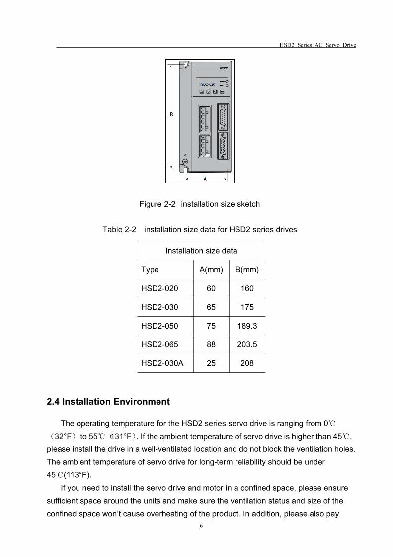
Figure 2-2 installation size sketch
Table 2-2 installation size data for HSD2 series drives
Installation size data
Type A(mm) B(mm)
HSD2-020 60 160
HSD2-030 65 175
HSD2-050 75 189.3
HSD2-065 88 203.5
HSD2-030A 25 208
2.4 Installation Environment
The operating temperature for the HSD2 series servo drive is ranging from 0℃(32°F) to 55℃(131°F). If the ambient temperature of servo drive is higher than 45℃,please install the drive in a well-ventilated location and do not block the ventilation holes.The ambient temperature of servo drive for long-term reliability should be under45℃(113°F).
If you need to install the servo drive and motor in a confined space, please ensuresufficient space around the units and make sure the ventilation status and size of theconfined space won’t cause overheating of the product. In addition, please also pay
HSD2 Series AC Servo Drive
7
your attention to the following cautions:1. The ambient humidity should be less than 80%, without condensing.2. Please keep the servo drive or motor away from the heat-radiating
equipment or in direct sunlight.3. Do not install the drive or motor in a location subjected to the environment
which contains water, corrosive gas or liquid, dust or oily dust, floating dust, metallicparticles.
4. Do not mount the servo drive or motor in the places where it will be subjectedto high levels of electromagnetic radiation.
5. Do not mount the servo drive or motor in a location where temperature andhumidity will exceed specification.
6. Do not mount the servo drive or motor in a location where vibration andshock will exceed specification.
7. The mounted position vibration should be less than 0.5G.
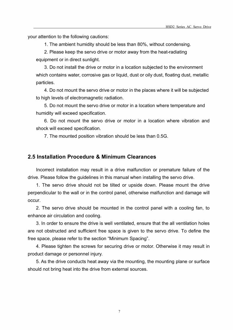
2.5 Installation Procedure & Minimum Clearances
Incorrect installation may result in a drive malfunction or premature failure of thedrive. Please follow the guidelines in this manual when installing the servo drive.
1. The servo drive should not be tilted or upside down. Please mount the driveperpendicular to the wall or in the control panel, otherwise malfunction and damage willoccur.
2. The servo drive should be mounted in the control panel with a cooling fan, toenhance air circulation and cooling.
3. In order to ensure the drive is well ventilated, ensure that the all ventilation holesare not obstructed and sufficient free space is given to the servo drive. To define thefree space, please refer to the section “Minimum Spacing”.
4. Please tighten the screws for securing drive or motor. Otherwise it may result inproduct damage or personnel injury.
5. As the drive conducts heat away via the mounting, the mounting plane or surfaceshould not bring heat into the drive from external sources.
HSD2 Series AC Servo Drive
8
Correct Incorrect
Figure2-3 The correct direction for mounting
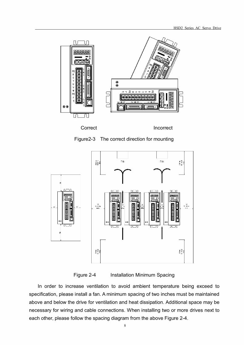
Figure 2-4 Installation Minimum Spacing
In order to increase ventilation to avoid ambient temperature being exceed tospecification, please install a fan. A minimum spacing of two inches must be maintainedabove and below the drive for ventilation and heat dissipation. Additional space may benecessary for wiring and cable connections. When installing two or more drives next toeach other, please follow the spacing diagram from the above Figure 2-4.
HSD2 Series AC Servo Drive
9
2.6 Connection Terminals
Please select the connecting terminals carefully and follow the instructions fromtable 2-3 and 2-4.
Table 2-3 Definition and function of the terminals
TerminalIdentification
TerminalDescription
Descriptions
R、S、TMain circuit
terminal
Used to connect three-phase AC main circuitpower depending on connecting servo drivemodel.
R、tControl circuit
terminal
Used to connect single-phase AC controlcircuit power. (Control circuit uses the samevoltage as the main circuit.)
U、V、W、
PEServo motor
output
Used to connect servo motorTerminalsymbol
Wire colour
U BrownV BlackW Grey
PEYellow and
green
PEGroundterminal
Used to connect with the grounding wires ofpower supply and servo motor.
CN1Encoder
connector
Used to connect with the encoder of servomotor. Please refer to section 3.2 for moredetails.
CN2 I/O connectorUsed to connect with external controllers.Please refer to section 3.3 for more details.
CN3Communicatio
n connector(Reserved)
Connect with personal computer (PC orlaptop).
HSD2 Series AC Servo Drive
10
Table 2-4 Cable specifications for the terminals
TerminalIdentification
TerminalDescription
Cable specification
R、S、TMain circuit
terminal1.5~2.5mm2
r、tControl circuit
terminal0.75~1 mm2
U、V、W Servo motor output 1.5~2.5 mm2
PE Ground terminal 1.5~2.5 mm2
CN1 Encoder connector≥0.14 mm2, 7 pair shieldedtwisted-pair cable
CN2 I/O connector≥0.14 mm2, shielded twisted-paircable
Wiring Cautions
Please read and follow up the below wiring precautions while performing wireconnections with the servo drive and servo motor.
1. Please ensure that the wiring of the main power supply terminal R/S/T andcontrol power supply terminal R/T are properly selected and connected, powerspecification is correct.
2. Please use shielded twisted-pair cables for wiring to voltage coupling andeliminate electrical noise and interference.
3. Please ensure a correct connection for U, V, W terminals, or it may not be able tostart the motor or cause galloping.
4. The ground terminal of the servo motor should be connect with the PE of theservo drive properly and ensure a single point grounding. The grounding cable requiresto be coarse as well.
5. As a residual hazardous voltage may remain inside the drive, please do not touchany of the terminals (R, S, T, & U, V ,W) or the cables connected to them after thepower has just been turned off. Wait for at least 10 minutes until the charging light is off
HSD2 Series AC Servo Drive
11
before you take any further actions with the drive.
6. With regards to the I/O signal cable, please use the recommended cable orsimilar shield cable. The total length of I/O signal cable shouldn’t exceed 3 meters,while encoder cable should be less than 15 meters. Please use a twisted-shield signalwire with grounding conductor for the encoder cable (CN1) and the position feedbacksignal connector (CN2). The wire length shouldn’t exceed 20meters. If it exceeds 20m,please choose a bigger wire diameter (double the existing one) of signal cable toreduce the signal fading.
7. The shield of shielded twisted-pair cables (encoder cable) should be connectedto the SHIELD end (ground terminal) of the servo drive.
8. The cables which connected to R, S, T and U, V, W terminals should be placedin separate conduits from the encoder or other signal cables. Separate them by at least30cm.
9. Please ensure the diode connecting direction of signal output relay is correct,otherwise it may lead to malfunction of the drive.
10. Please install a non fuse type circuit breaker (NFB) to achieve external powercut offs when the servo drive is in a malfunction status.
11. Shut down the power supply if the servo drive is not being used for a long term.
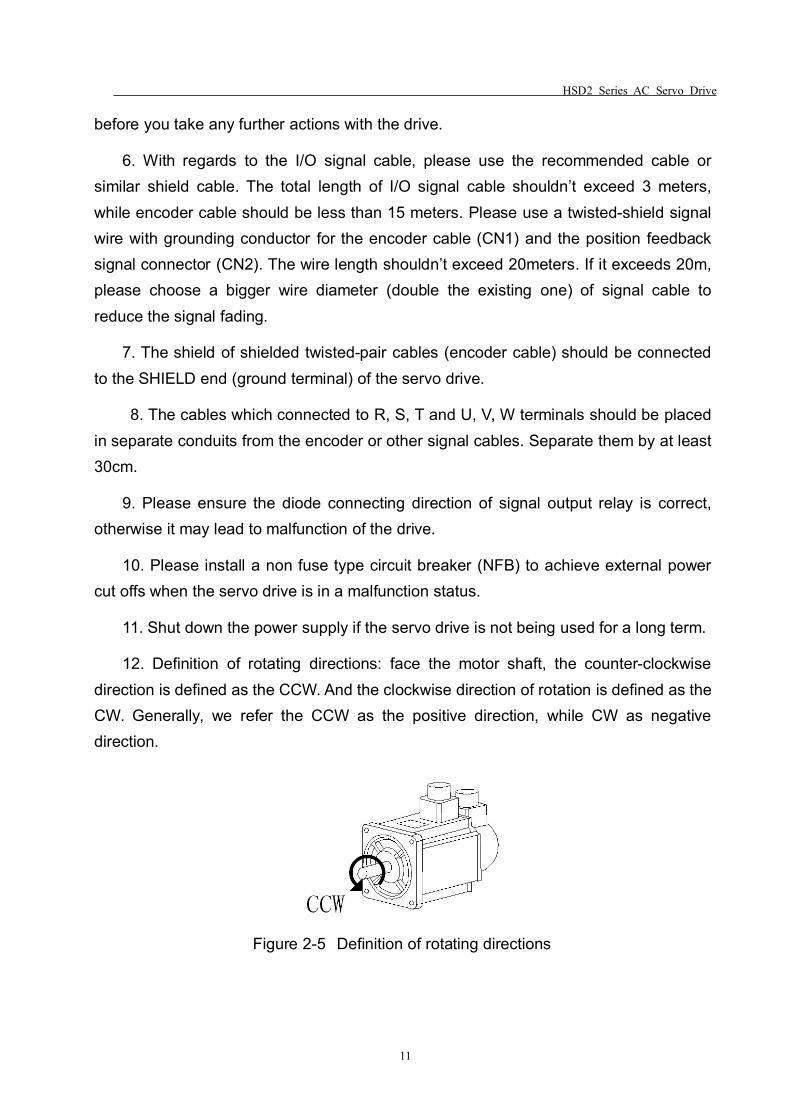
12. Definition of rotating directions: face the motor shaft, the counter-clockwisedirection is defined as the CCW. And the clockwise direction of rotation is defined as theCW. Generally, we refer the CCW as the positive direction, while CW as negativedirection.
Figure 2-5 Definition of rotating directions
HSD2 Series AC Servo Drive
12
Chapter 3 Signal Interface And Wiring
CN1, CN2, CN3 are the signal interfaces of the servo drive, while CN3 is thecommunication port, (reserved).
This chapter provides the definitions and standard wiring/connections for the threeports.
3.1 Overview
1. CN1 is an encoder connector, used for receiving position signals from servomotor.
2. HSD2 series servo drive is only applicable with incremental opticalencoder(resolution 2500ppr)
3. Incremental optical encoder includes 6 signals: U V W A B Z respectively. Itadopts differential encoder signal output(15-line output generally).
4. CN2 is the I/O connector, used to receive control signal from the controller, andoutput the feedback signal to the controller by return.
5. Control signal generally include pulse command signal: PULS+, PULS-, anddirection signal: SIGN+, SIGN-,analog speed command signal :AS+, AS-, drivesignal: SON etc.
6. The feedback signal include encoder signal: A+, A-, B+, B-, Z+, Z-, Z ;signal OC,output signal :CZ, servo drive alarm signal: ALM+, ALM-, etc.
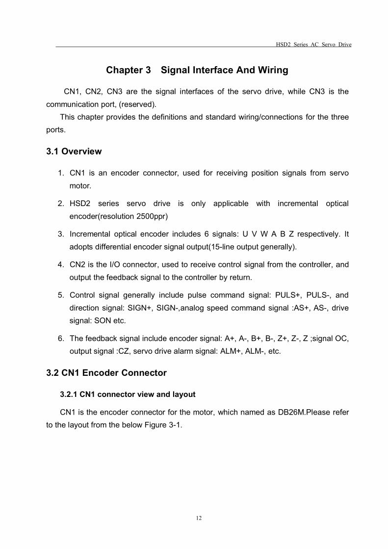
3.2 CN1 Encoder Connector
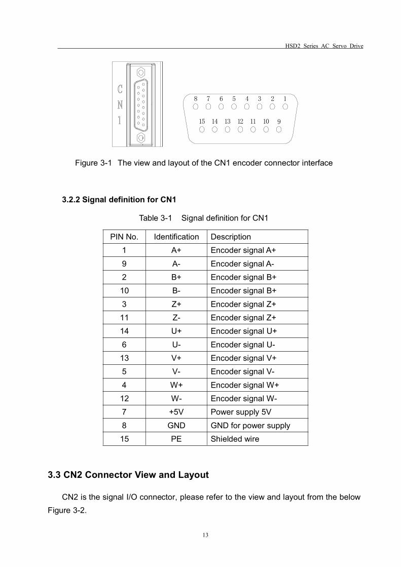
3.2.1 CN1 connector view and layout
CN1 is the encoder connector for the motor, which named as DB26M.Please referto the layout from the below Figure 3-1.
HSD2 Series AC Servo Drive
13
12345678
15 14 13 12 11 10 9
Figure 3-1 The view and layout of the CN1 encoder connector interface
3.2.2 Signal definition for CN1
Table 3-1 Signal definition for CN1
PIN No. Identification Description1 A+ Encoder signal A+9 A- Encoder signal A-2 B+ Encoder signal B+10 B- Encoder signal B+3 Z+ Encoder signal Z+11 Z- Encoder signal Z+14 U+ Encoder signal U+6 U- Encoder signal U-13 V+ Encoder signal V+5 V- Encoder signal V-4 W+ Encoder signal W+12 W- Encoder signal W-7 +5V Power supply 5V8 GND GND for power supply15 PE Shielded wire
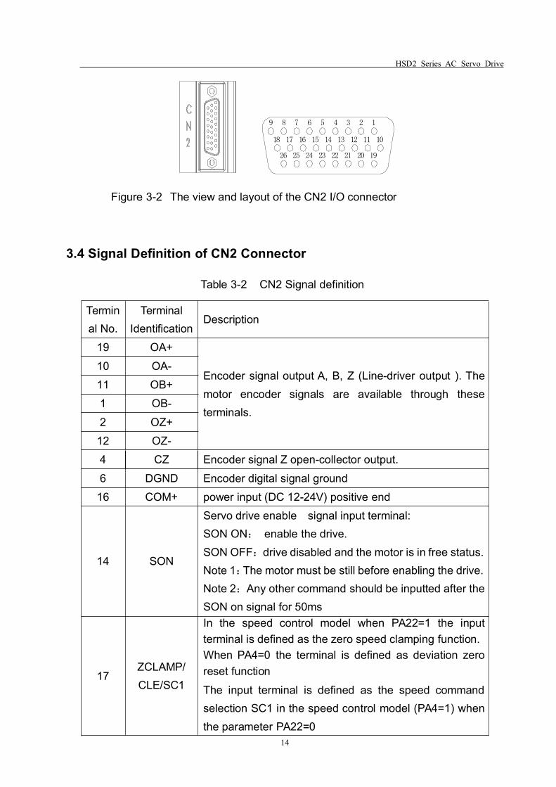
3.3 CN2 Connector View and Layout
CN2 is the signal I/O connector, please refer to the view and layout from the belowFigure 3-2.
HSD2 Series AC Servo Drive
14
123456789
101112131415161718
1920212223242526
Figure 3-2 The view and layout of the CN2 I/O connector
3.4 Signal Definition of CN2 Connector
Table 3-2 CN2 Signal definition
Terminal No.
TerminalIdentification
Description
19 OA+
Encoder signal output A, B, Z (Line-driver output ). Themotor encoder signals are available through theseterminals.
10 OA-11 OB+1 OB-2 OZ+
12 OZ-4 CZ Encoder signal Z open-collector output.6 DGND Encoder digital signal ground
16 COM+ power input (DC 12-24V) positive end
14 SON
Servo drive enable signal input terminal:SON ON: enable the drive.SON OFF:drive disabled and the motor is in free status.Note 1:The motor must be still before enabling the drive.Note 2:Any other command should be inputted after theSON on signal for 50ms
17ZCLAMP/CLE/SC1
In the speed control model when PA22=1 the inputterminal is defined as the zero speed clamping function.When PA4=0 the terminal is defined as deviation zeroreset functionThe input terminal is defined as the speed commandselection SC1 in the speed control model (PA4=1) whenthe parameter PA22=0
HSD2 Series AC Servo Drive
15
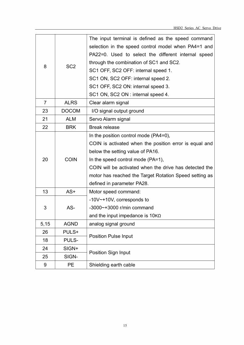
8 SC2
The input terminal is defined as the speed commandselection in the speed control model when PA4=1 andPA22=0. Used to select the different internal speedthrough the combination of SC1 and SC2.SC1 OFF, SC2 OFF: internal speed 1.SC1 ON, SC2 OFF: internal speed 2.SC1 OFF, SC2 ON: internal speed 3.SC1 ON, SC2 ON : internal speed 4.
7 ALRS Clear alarm signal23 DOCOM I/O signal output ground21 ALM Servo Alarm signal22 BRK Break release
20 COIN
In the position control mode (PA4=0),COIN is activated when the position error is equal andbelow the setting value of PA16.In the speed control mode (PA=1),COIN will be activated when the drive has detected themotor has reached the Target Rotation Speed setting asdefined in parameter PA28.
13 AS+ Motor speed command:-10V~+10V, corresponds to-3000~+3000 r/min commandand the input impedance is 10KΩ
3 AS-
5,15 AGND analog signal ground26 PULS+
Position Pulse Input18 PULS-24 SIGN+
Position Sign Input25 SIGN-9 PE Shielding earth cable
HSD2 Series AC Servo Drive
16
3.5 I/O Interface
3.5.1 Digital signal input interface
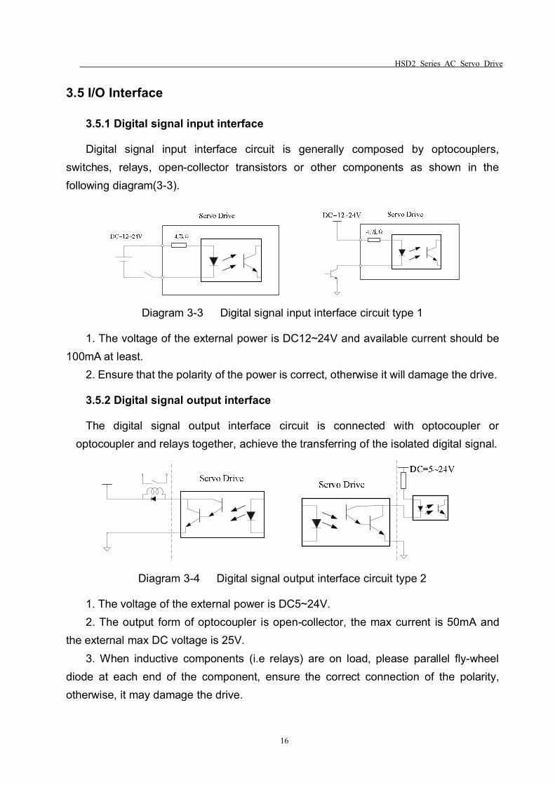
Digital signal input interface circuit is generally composed by optocouplers,switches, relays, open-collector transistors or other components as shown in thefollowing diagram(3-3).
Diagram 3-3 Digital signal input interface circuit type 1
1. The voltage of the external power is DC12~24V and available current should be100mA at least.
2. Ensure that the polarity of the power is correct, otherwise it will damage the drive.
3.5.2 Digital signal output interface
The digital signal output interface circuit is connected with optocoupler oroptocoupler and relays together, achieve the transferring of the isolated digital signal.
Diagram 3-4 Digital signal output interface circuit type 2
1. The voltage of the external power is DC5~24V.2. The output form of optocoupler is open-collector, the max current is 50mA and
the external max DC voltage is 25V.3. When inductive components (i.e relays) are on load, please parallel fly-wheel
diode at each end of the component, ensure the correct connection of the polarity,otherwise, it may damage the drive.
HSD2 Series AC Servo Drive
17
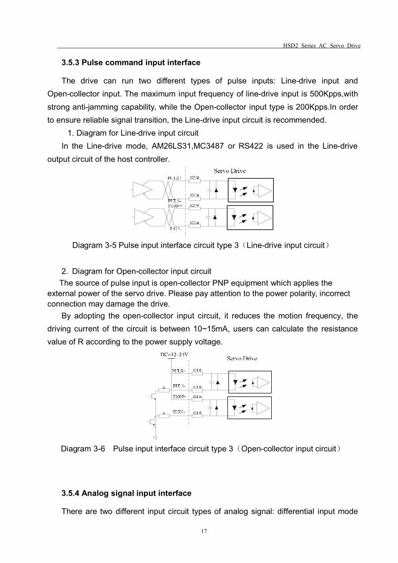
3.5.3 Pulse command input interface
The drive can run two different types of pulse inputs: Line-drive input andOpen-collector input. The maximum input frequency of line-drive input is 500Kpps,withstrong anti-jamming capability, while the Open-collector input type is 200Kpps.In orderto ensure reliable signal transition, the Line-drive input circuit is recommended.
1. Diagram for Line-drive input circuitIn the Line-drive mode, AM26LS31,MC3487 or RS422 is used in the Line-drive
output circuit of the host controller.
Diagram 3-5 Pulse input interface circuit type 3(Line-drive input circuit)
2. Diagram for Open-collector input circuitThe source of pulse input is open-collector PNP equipment which applies the
external power of the servo drive. Please pay attention to the power polarity, incorrectconnection may damage the drive.
By adopting the open-collector input circuit, it reduces the motion frequency, thedriving current of the circuit is between 10~15mA, users can calculate the resistancevalue of R according to the power supply voltage.
Diagram 3-6 Pulse input interface circuit type 3(Open-collector input circuit)
3.5.4 Analog signal input interface
There are two different input circuit types of analog signal: differential input mode
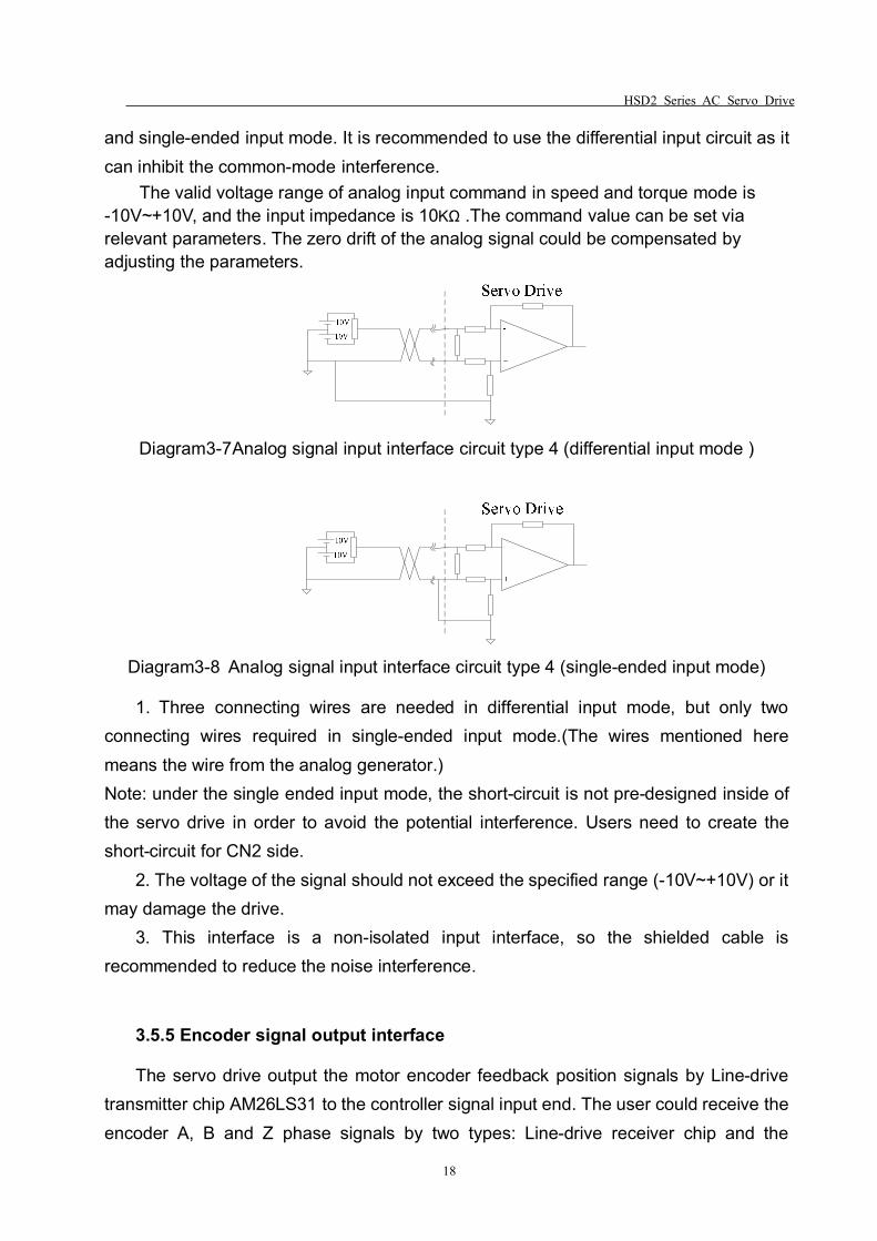
HSD2 Series AC Servo Drive
18
and single-ended input mode. It is recommended to use the differential input circuit as itcan inhibit the common-mode interference.
The valid voltage range of analog input command in speed and torque mode is-10V~+10V, and the input impedance is 10KΩ .The command value can be set viarelevant parameters. The zero drift of the analog signal could be compensated byadjusting the parameters.
Diagram3-7Analog signal input interface circuit type 4 (differential input mode )
Diagram3-8 Analog signal input interface circuit type 4 (single-ended input mode)
1. Three connecting wires are needed in differential input mode, but only twoconnecting wires required in single-ended input mode.(The wires mentioned heremeans the wire from the analog generator.)Note: under the single ended input mode, the short-circuit is not pre-designed inside ofthe servo drive in order to avoid the potential interference. Users need to create theshort-circuit for CN2 side.
2. The voltage of the signal should not exceed the specified range (-10V~+10V) or itmay damage the drive.
3. This interface is a non-isolated input interface, so the shielded cable isrecommended to reduce the noise interference.
3.5.5 Encoder signal output interface
The servo drive output the motor encoder feedback position signals by Line-drivetransmitter chip AM26LS31 to the controller signal input end. The user could receive theencoder A, B and Z phase signals by two types: Line-drive receiver chip and the
HSD2 Series AC Servo Drive
19
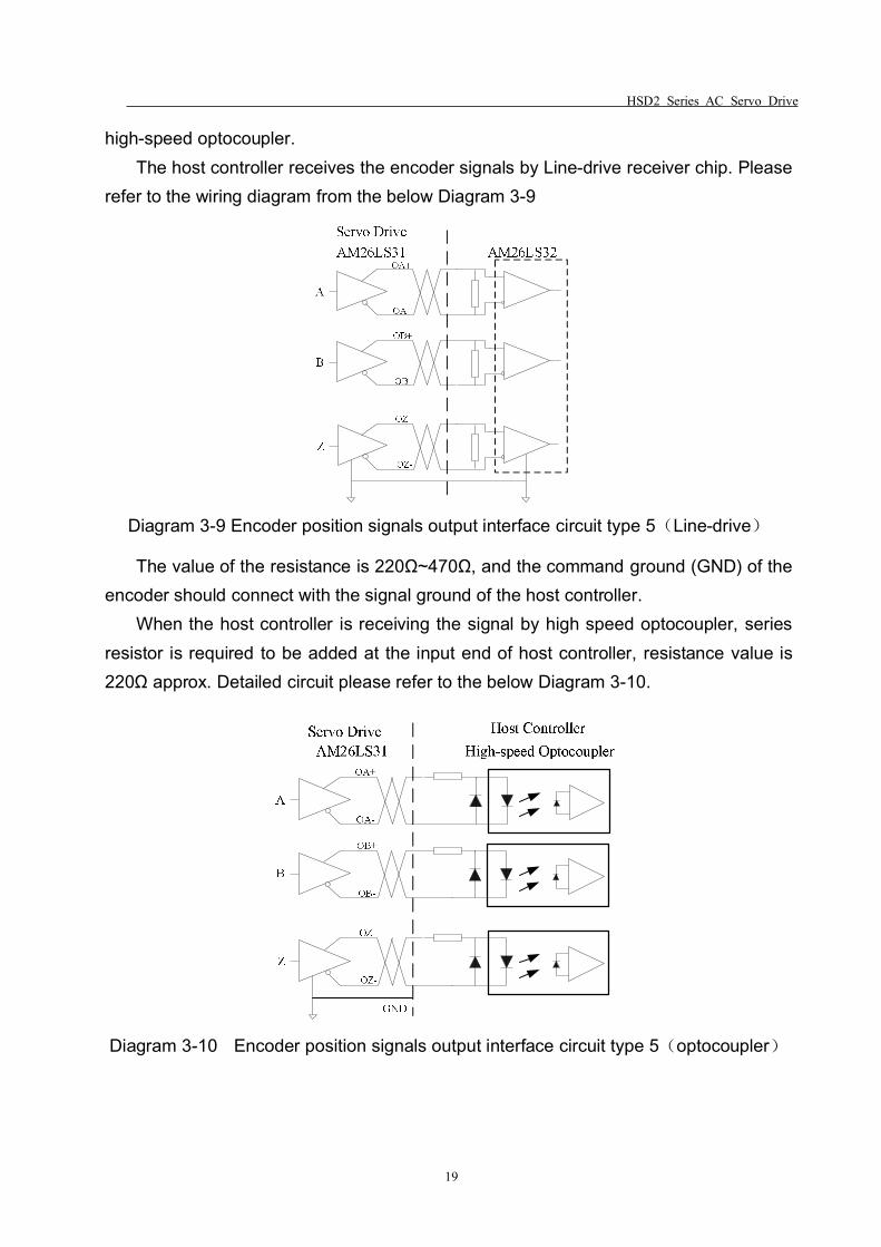
high-speed optocoupler.The host controller receives the encoder signals by Line-drive receiver chip. Please
refer to the wiring diagram from the below Diagram 3-9
Diagram 3-9 Encoder position signals output interface circuit type 5(Line-drive)
The value of the resistance is 220Ω~470Ω, and the command ground (GND) of theencoder should connect with the signal ground of the host controller.
When the host controller is receiving the signal by high speed optocoupler, seriesresistor is required to be added at the input end of host controller, resistance value is220Ω approx. Detailed circuit please refer to the below Diagram 3-10.
Diagram 3-10 Encoder position signals output interface circuit type 5(optocoupler)
HSD2 Series AC Servo Drive
20
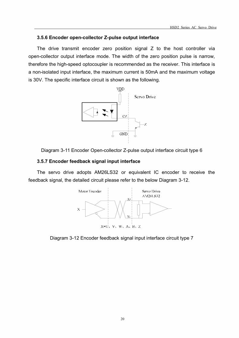
3.5.6 Encoder open-collector Z-pulse output interface
The drive transmit encoder zero position signal Z to the host controller viaopen-collector output interface mode. The width of the zero position pulse is narrow,therefore the high-speed optocoupler is recommended as the receiver. This interface isa non-isolated input interface, the maximum current is 50mA and the maximum voltageis 30V. The specific interface circuit is shown as the following.
Diagram 3-11 Encoder Open-collector Z-pulse output interface circuit type 6
3.5.7 Encoder feedback signal input interface
The servo drive adopts AM26LS32 or equivalent IC encoder to receive thefeedback signal, the detailed circuit please refer to the below Diagram 3-12.
Diagram 3-12 Encoder feedback signal input interface circuit type 7
HSD2 Series AC Servo Drive
21
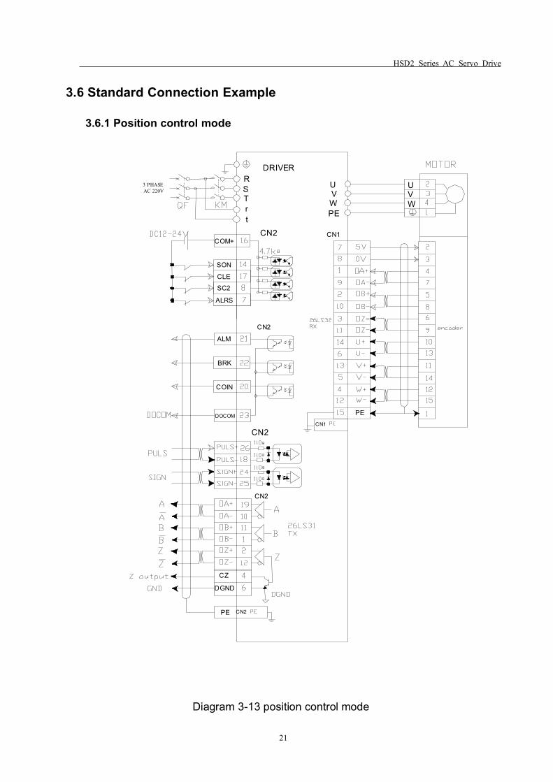
3.6 Standard Connection Example
3.6.1 Position control mode
3 PHASEAC 220V
RDRIVER
CN2
CN2
CN2
SON
CLESC2
ALRS
ALM
BRK
COIN
DOCOM
CZ
DGND
PE CN2
CN1
PECN1
CN2
STrt
COM+
PEWVU U
VW
Diagram 3-13 position control mode
HSD2 Series AC Servo Drive
22
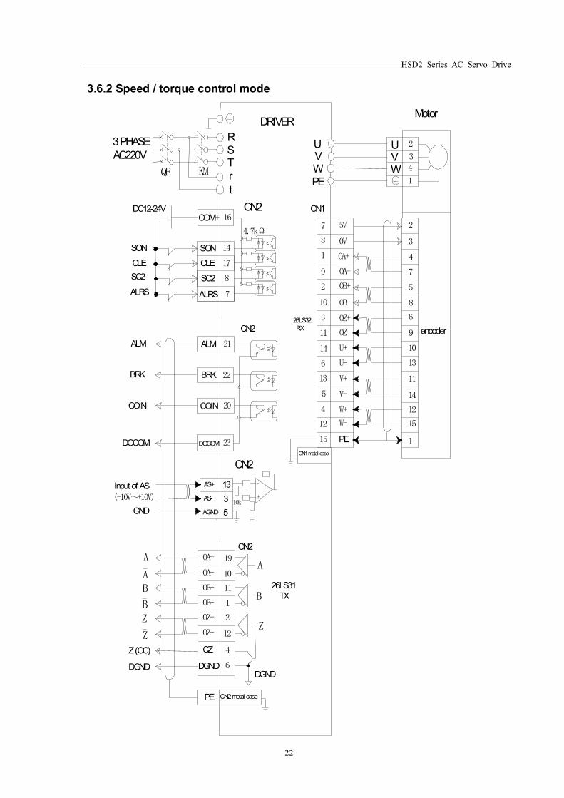
3.6.2 Speed / torque control mode
3 PHASEAC220V
QF KM
RDRIVER
2
3
4
1
Motor
CN2
4.7kΩ
DC12-24V
SONCLESC2
ALRS
CN2 encoder26LS32 RX
ALM
BRK
COIN
DOCOM
Z (OC)
DGND
CN2
A
B
Z
DGND
26LS31 TX
A
AB
BZ
Z
SON 14
CLE
SC2
ALRS
17
8
7
ALM
BRK
COIN
DOCOM
21
22
20
23
19
10
11
1
2
12
4
6
OA+
OA-
OB+
OB-
OZ+
OZ-
CZ
DGND
PE CN2 metal case
CN1
7
8
1
9
2
10
3
11
14
6
13
5
4
12
15
5V
0V
OA+
OA-
OB+
OB-
OZ+
OZ-
U+
U-
V+
V-
W+
W-
PE
2
3
4
7
5
8
6
9
10
13
11
14
12
15
1CN1 metal case
CN2
STrt
COM+ 16
PEWVU U
VW
AS+
AS-
AGND
1335
10k
input of AS(-10V~+10V)
GND
HSD2 Series AC Servo Drive
23
Chapter 4 Panel Display & Operation
This chapter describes the panel status and basic operations of the digital keypad.
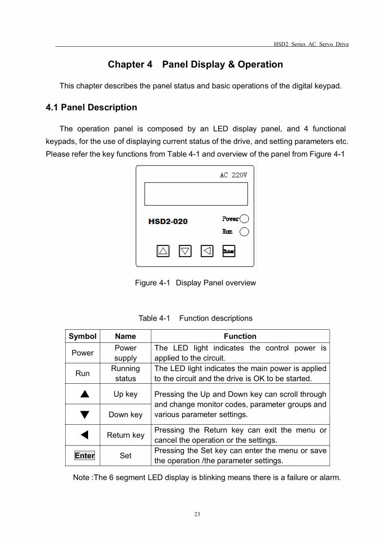
4.1 Panel Description
The operation panel is composed by an LED display panel, and 4 functionalkeypads, for the use of displaying current status of the drive, and setting parameters etc.Please refer the key functions from Table 4-1 and overview of the panel from Figure 4-1
Figure 4-1 Display Panel overview
Table 4-1 Function descriptions
Symbol Name Function
Power Powersupply
The LED light indicates the control power isapplied to the circuit.
Run Runningstatus
The LED light indicates the main power is appliedto the circuit and the drive is OK to be started.
Up key Pressing the Up and Down key can scroll throughand change monitor codes, parameter groups andvarious parameter settings.Down key
Return key Pressing the Return key can exit the menu orcancel the operation or the settings.
Enter Set Pressing the Set key can enter the menu or savethe operation /the parameter settings.
Note :The 6 segment LED display is blinking means there is a failure or alarm.
HSD2 Series AC Servo Drive
24
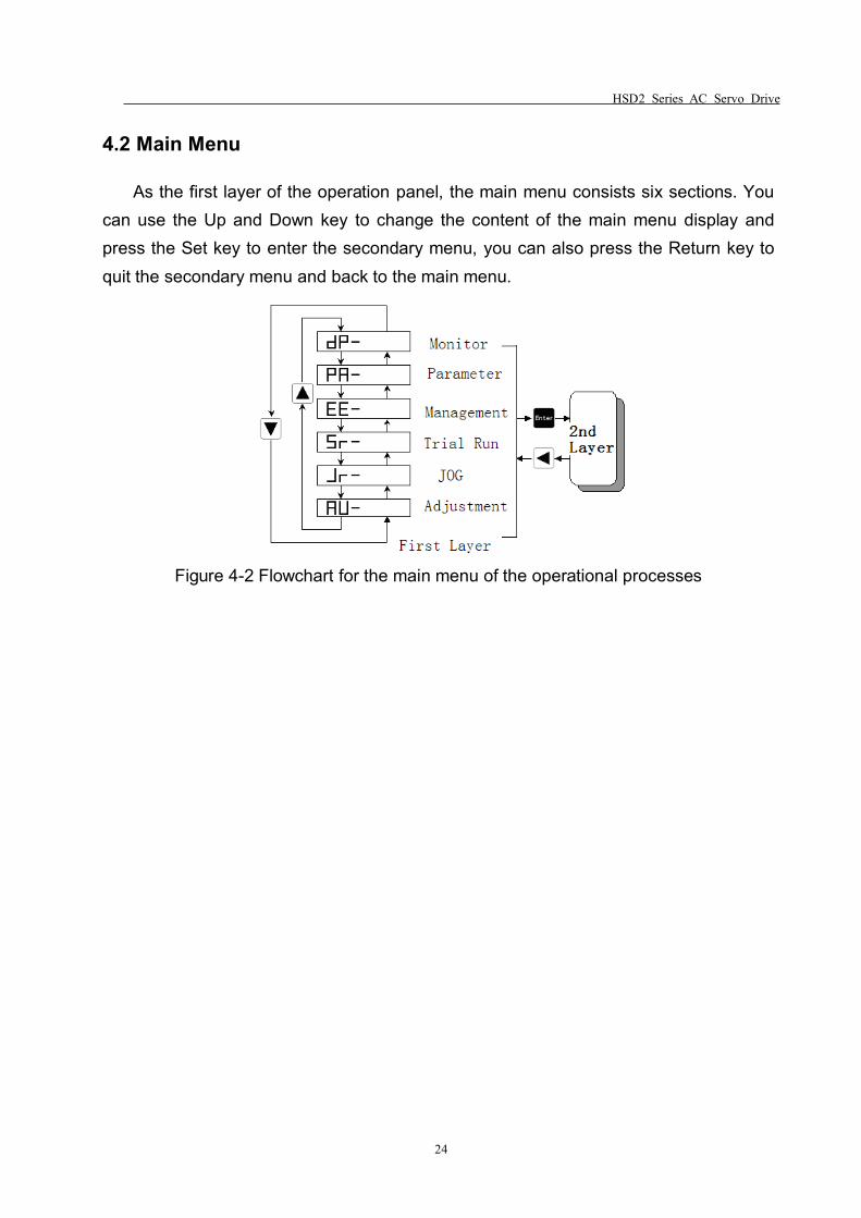
4.2 Main Menu
As the first layer of the operation panel, the main menu consists six sections. Youcan use the Up and Down key to change the content of the main menu display andpress the Set key to enter the secondary menu, you can also press the Return key toquit the secondary menu and back to the main menu.
Figure 4-2 Flowchart for the main menu of the operational processes
HSD2 Series AC Servo Drive
25
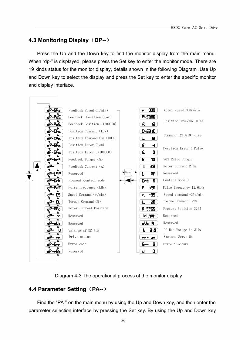
4.3 Monitoring Display(DP--)
Press the Up and the Down key to find the monitor display from the main menu.When “dp-” is displayed, please press the Set key to enter the monitor mode. There are19 kinds status for the monitor display, details shown in the following Diagram .Use Upand Down key to select the display and press the Set key to enter the specific monitorand display interface.
Feedback Speed(r/min)
Feedback Position(Low)
Feedback Position(X100000)
Position Command(Low)
Position Command(X100000)
Position Error(Low)
Position Error(X100000)
Feedback Torque(%)
Feedback Current(A)
Reserved
Present Control Mode
Pulse frequency(kHz)
Speed Command(r/min)
Torque Command(%)
Motor Current Position
Reserved
Reserved
Voltage of DC Bus
Drive status
Error code
Reserved
Motor speed1000r/min
Position 1245806 Pulse
Command 1245810 Pulse
Position Error 4 Pulse
70% Rated Torque
Motor current 2.3A
Reserved
Control mode 0
Pulse frequency 12.6kHz
Speed command -35r/min
Torque Command -20%
Present Position 3265
Reserved
Reserved
DC Bus Votage is 310V
Status:Servo On
Error 9 occurs
Enter
Diagram 4-3 The operational process of the monitor display
4.4 Parameter Setting(PA--)
Find the “PA-” on the main menu by using the Up and Down key, and then enter theparameter selection interface by pressing the Set key. By using the Up and Down key
HSD2 Series AC Servo Drive
26
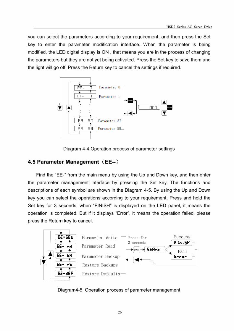
you can select the parameters according to your requirement, and then press the Setkey to enter the parameter modification interface. When the parameter is beingmodified, the LED digital display is ON , that means you are in the process of changingthe parameters but they are not yet being activated. Press the Set key to save them andthe light will go off. Press the Return key to cancel the settings if required.
Diagram 4-4 Operation process of parameter settings
4.5 Parameter Management(EE--)
Find the “EE-” from the main menu by using the Up and Down key, and then enterthe parameter management interface by pressing the Set key. The functions anddescriptions of each symbol are shown in the Diagram 4-5. By using the Up and Downkey you can select the operations according to your requirement. Press and hold theSet key for 3 seconds, when “FINISH” is displayed on the LED panel, it means theoperation is completed. But if it displays “Error”, it means the operation failed, pleasepress the Return key to cancel.
Parameter Write
Parameter Backup
Press for3 seconds
Success
FailEnter
Parameter Read
Restore Backups
Restore Defaults
Diagram4-5 Operation process of parameter management
HSD2 Series AC Servo Drive
27
EE-set Parameters write: It indicates that all the parameters will be storedin the EEPROM parameters district, power-off is not going to losethe saved settings.
EE-rd Parameters read: you can read the parameters from EEPROMdistrict, modify the parameters according to your request,however,when the power goes off, your revised data won’t besaved.
EE-rs Parameters restore: you can read the data from the EEPROMparameter list, do the changes according to your requirement,perform a write operation to save the revised parameterspermanently.
EE-def Restore the default parameters: when the parameters aredisordered or changed improperly, you can bring all of the defaultsinto the parameter list, and then write the parameters into theEEPROM. After this operation, you should ensure that the motorcode (PA1) is matching with the motor you are using.
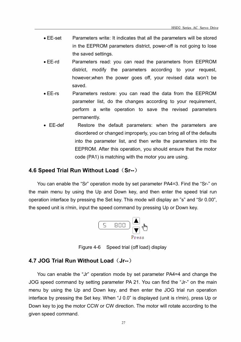
4.6 Speed Trial Run Without Load(Sr--)
You can enable the “Sr” operation mode by set parameter PA4=3. Find the “Sr-” onthe main menu by using the Up and Down key, and then enter the speed trial runoperation interface by pressing the Set key. This mode will display an ”s” and “Sr 0.00”,the speed unit is r/min, input the speed command by pressing Up or Down key.
Figure 4-6 Speed trial (off load) display
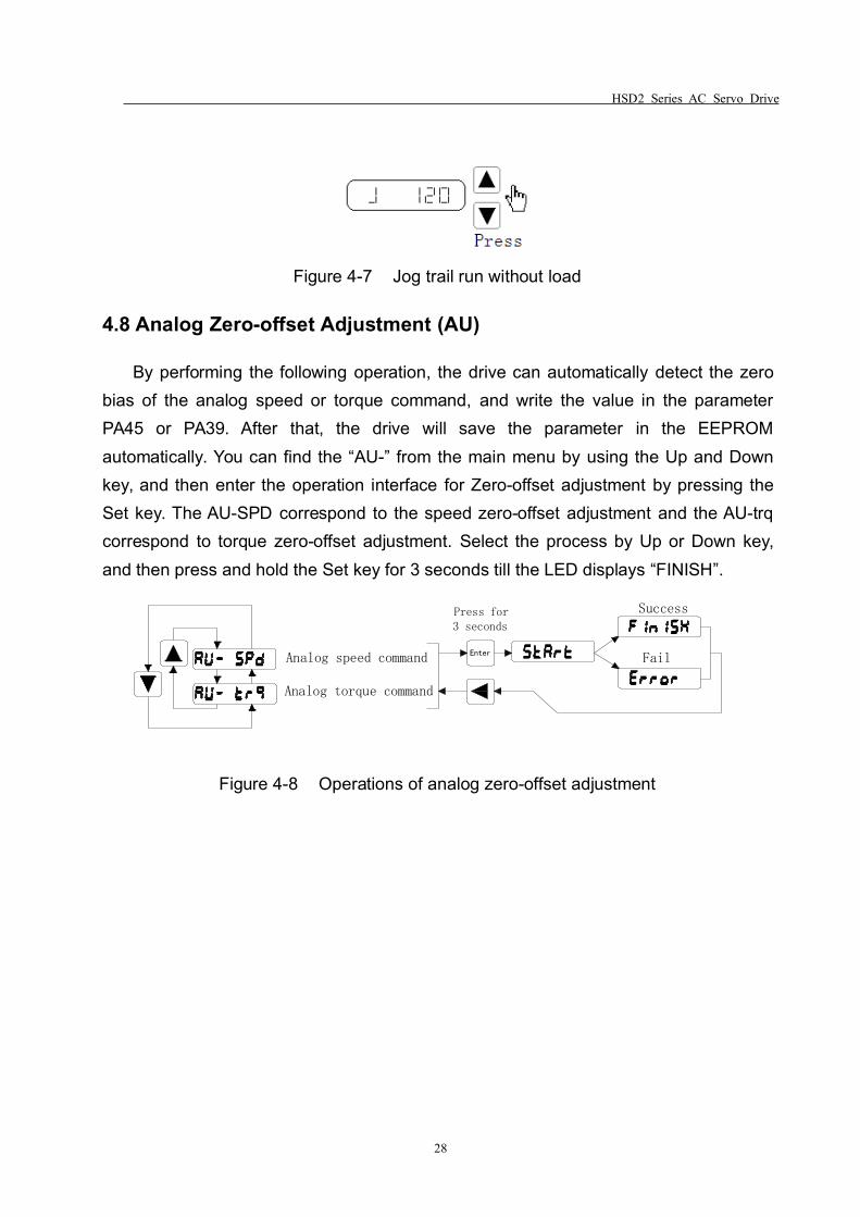
4.7 JOG Trial Run Without Load(Jr--)
You can enable the “Jr” operation mode by set parameter PA4=4 and change theJOG speed command by setting parameter PA 21. You can find the “Jr-” on the mainmenu by using the Up and Down key, and then enter the JOG trial run operationinterface by pressing the Set key. When “J 0.0” is displayed (unit is r/min), press Up orDown key to jog the motor CCW or CW direction. The motor will rotate according to thegiven speed command.
HSD2 Series AC Servo Drive
28
Figure 4-7 Jog trail run without load
4.8 Analog Zero-offset Adjustment (AU)
By performing the following operation, the drive can automatically detect the zerobias of the analog speed or torque command, and write the value in the parameterPA45 or PA39. After that, the drive will save the parameter in the EEPROMautomatically. You can find the “AU-” from the main menu by using the Up and Downkey, and then enter the operation interface for Zero-offset adjustment by pressing theSet key. The AU-SPD correspond to the speed zero-offset adjustment and the AU-trqcorrespond to torque zero-offset adjustment. Select the process by Up or Down key,and then press and hold the Set key for 3 seconds till the LED displays “FINISH”.
EnterAnalog speed command
Analog torque command
Press for3 seconds
Success
Fail
Figure 4-8 Operations of analog zero-offset adjustment
HSD2 Series AC Servo Drive
29
Chapter 5 Trial Run and Tuning
This chapter describes trial run for servo drive and motor, including the trial runwithout load and introductions about the operation mode of the drive. Please alwaysmake sure that you perform a trial run without load first, before an on-loadrunning/operation.
5.1 Inspection Without Load
In order to prevent accidents and avoid any potential damages to the servo drive andmechanical system, the trial run should be performed without load. Please remove theload of the servo motor, including coupling on the shaft and accessories so as to avoidany damage on servo drive or mechanism. This is aiming to avoid the falling off of thedisassembled parts of the motor shaft and indirectly causing the personnel injury orequipment damage during operation.Always remember to perform the trial without load first before you connect the drive withpower supply.Before the trial run (without load), please inspect the following points carefully:
1. Check the drive and motor appearance to see whether or not there is anyobvious damage.
2. Check all the wiring to see if they are correctly connected, especially R, S, T, U, V,W and PE terminal. The terminals should be connected with the specified cables.
3. Ensure that there are no extra things inside the drive, such as conductive objectsand flammable objects.
4. Confirm that the electromagnetic brake is working normally if brake is required.
5. Please make sure the external voltage level of the servo drive is correct.
6. Make sure that the cable and the mechanical parts are not intertwined, to avoidwear or pulling phenomenon at the run time.
7. Ensure that the servo drive and motor are well connected to the ground.
Please pay attention to the following notes when you are undertaking the trial run.1. Please check if there is any abnormal display of the power indicator and LED
display panel.
2. Ensure that all user-defined parameters are being set correctly. The
HSD2 Series AC Servo Drive
30
characteristics of different machinery equipment differ from each other, in order to avoidaccident or cause potential damage, do not adjust the parameter abnormally andchange parameter to an excessive value.
3. Make sure that the servo drive is off when you set parameters.
4. Check the vibrations and sound during operation. If the servo motor is vibratingor there are unusual noises while the motor is running, please contact your localdistributor or manufacturer for further assistance.
5. Please make sure that all the relays are working properly, contact our localdistributor or us directly if there is any abnormal case.
5.1.1 Apply power to the drive
Turn on the control power supply (leave the main power off at the moment), theLED indicator should be lighted, if there is any alarm displayed on the panel, pleasecheck the wiring.
Next, connect the main power supply, the RUN indicator should be on, if not orthere is any alarm, check the wiring, or replace your drive.
5.1.2 JOG trial run without load
It is very convenient to use JOG trial run without load to test the servo drive andmotor as it doesn’t require an extra wiring. In order to ensure a safe trial run, it isrecommended to set JOG speed at low speed level such as 100r/min. The JOG speedcould be set in the parameter PA21.
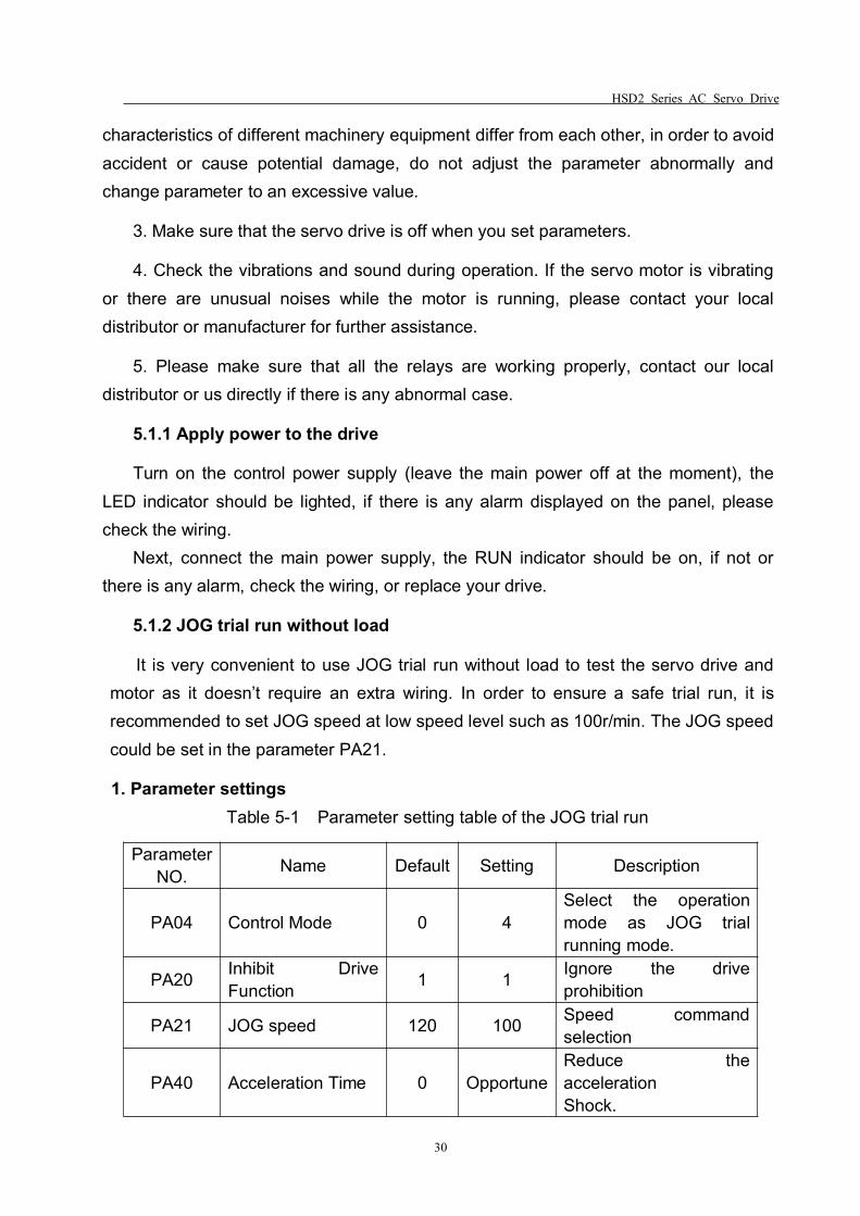
1. Parameter settingsTable 5-1 Parameter setting table of the JOG trial run
ParameterNO. Name Default Setting Description
PA04 Control Mode 0 4Select the operationmode as JOG trialrunning mode.
PA20 Inhibit DriveFunction 1 1 Ignore the drive
prohibition
PA21 JOG speed 120 100 Speed commandselection
PA40 Acceleration Time 0 OpportuneReduce theaccelerationShock.
HSD2 Series AC Servo Drive
31
PA41 Deceleration Time 0 OpportuneReduce thedecelerationShock.
PA53 Enabled Word 1 1 1 Enable the drive withoutthe external force
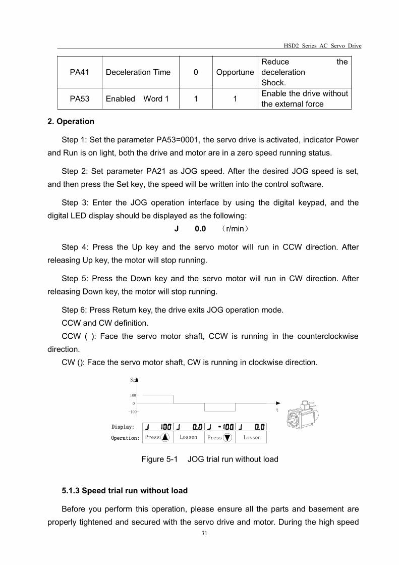
2. Operation
Step 1: Set the parameter PA53=0001, the servo drive is activated, indicator Powerand Run is on light, both the drive and motor are in a zero speed running status.
Step 2: Set parameter PA21 as JOG speed. After the desired JOG speed is set,and then press the Set key, the speed will be written into the control software.
Step 3: Enter the JOG operation interface by using the digital keypad, and thedigital LED display should be displayed as the following:
J 0.0 (r/min)
Step 4: Press the Up key and the servo motor will run in CCW direction. Afterreleasing Up key, the motor will stop running.
Step 5: Press the Down key and the servo motor will run in CW direction. Afterreleasing Down key, the motor will stop running.
Step 6: Press Return key, the drive exits JOG operation mode.CCW and CW definition.CCW ( ): Face the servo motor shaft, CCW is running in the counterclockwise
direction.CW (): Face the servo motor shaft, CW is running in clockwise direction.
Display:
Press
-100
0
100
t
Sr
Operation: Lossen LossenPress
Figure 5-1 JOG trial run without load
5.1.3 Speed trial run without load
Before you perform this operation, please ensure all the parts and basement areproperly tightened and secured with the servo drive and motor. During the high speed
HSD2 Series AC Servo Drive
32
running, any unsecured parts can cause malfunction and personnel injury.1. Parameter setting
Table 5-2 Parameters for the speed trial run
Parameter Name Default Setting Description
PA04 Control mode 0 3Select the operation modeas speed trial running controlmode.
PA20 Inhibit DriveFunction 1 1 Ignore the drive prohibition
PA53 Control word 1 1 1 Enable the drive without theexternal signal
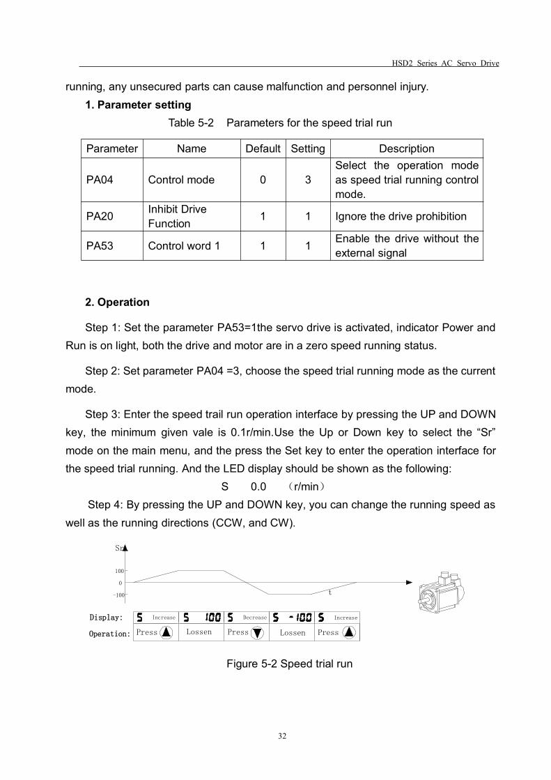
2. Operation
Step 1: Set the parameter PA53=1the servo drive is activated, indicator Power andRun is on light, both the drive and motor are in a zero speed running status.
Step 2: Set parameter PA04 =3, choose the speed trial running mode as the currentmode.
Step 3: Enter the speed trail run operation interface by pressing the UP and DOWNkey, the minimum given vale is 0.1r/min.Use the Up or Down key to select the “Sr”mode on the main menu, and the press the Set key to enter the operation interface forthe speed trial running. And the LED display should be shown as the following:
S 0.0 (r/min)Step 4: By pressing the UP and DOWN key, you can change the running speed as
well as the running directions (CCW, and CW).
-100
0
100
t
Sr
Press Press PressLossenLossen
Display:
Operation:
Increase Decrease Increase
Figure 5-2 Speed trial run
HSD2 Series AC Servo Drive
33
5.2 Position Control Mode
The position control mode is usually used for the applications requiring precisionpositioning, i.e, industry positioning machine. Before position trial run, please carry outthe following inspections:
1. Ensure that all wiring is correct and wiring terminals of the servo drive and motorare correctly insulated.
2. Ensure all the parts and basement are properly tightened and secured with theservo drive and motor. During the high speed running, any unsecured parts can causemalfunction and personnel injury.
5.2.1 Simple position control system
A simple position control system only requires two sets of position pulse commandsignals, drive enable signal, prohibited drive signal, servo ready and servo alarm outputsignals. Please refer to the wiring from the below Diagram 5-3.
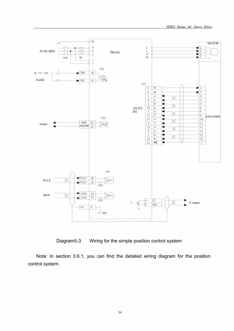
HSD2 Series AC Servo Drive
34
3P AC 220V
DC 12~24V
Enable
Driver
MOTOR2341
2
3
4
7
5
86
9
10
13
11
14
12
15
1
ENCODER
4.7k
R
S
T
r
t
NFB
COM+
SON
16
14
PE
MC
CN1
26LS32RX
UVWPE
5V
8
1
9
2
A+
B+
10
3 Z+
11
14 U+
6 U-
13 V+
5
4
12
W+
15 PEW-
V-
Z-
B-
A-
0V
CN2
ALMDOCOM
21
23
PULS+
PULS-
26
18
SIGN+
SIGN-
24
25
FG 9
FG
6
4 CZ
GNDZ output
220
220Z
Alarm
PULS
SIGN
CN2
CN2
7
Diagram5-3 Wiring for the simple position control system
Note: In section 3.6.1, you can find the detailed wiring diagram for the positioncontrol system.
HSD2 Series AC Servo Drive
35
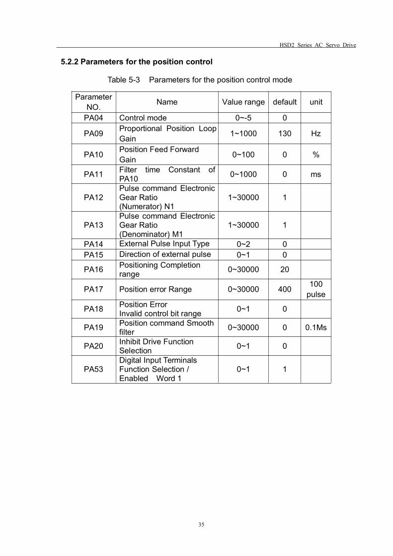
5.2.2 Parameters for the position control
Table 5-3 Parameters for the position control mode
ParameterNO. Name Value range default unit
PA04 Control mode 0~-5 0
PA09 Proportional Position LoopGain 1~1000 130 Hz
PA10 Position Feed ForwardGain 0~100 0 %
PA11 Filter time Constant ofPA10 0~1000 0 ms
PA12Pulse command ElectronicGear Ratio(Numerator) N1
1~30000 1
PA13Pulse command ElectronicGear Ratio(Denominator) M1
1~30000 1
PA14 External Pulse Input Type 0~2 0PA15 Direction of external pulse 0~1 0
PA16 Positioning Completionrange 0~30000 20
PA17 Position error Range 0~30000 400 100pulse
PA18 Position ErrorInvalid control bit range 0~1 0
PA19 Position command Smoothfilter 0~30000 0 0.1Ms
PA20 Inhibit Drive FunctionSelection 0~1 0
PA53Digital Input TerminalsFunction Selection /Enabled Word 1
0~1 1
HSD2 Series AC Servo Drive
36
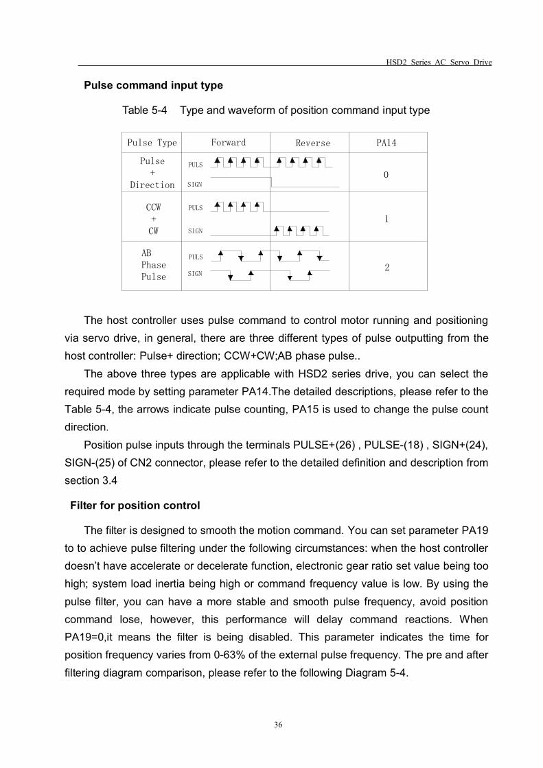
Pulse command input type
Table 5-4 Type and waveform of position command input type
PULS
SIGN
PULS
SIGN
PULS
SIGN
Forward ReversePulse Type PA14
Pulse+
Direction
CCW+CW
ABPhasePulse
0
1
2
The host controller uses pulse command to control motor running and positioningvia servo drive, in general, there are three different types of pulse outputting from thehost controller: Pulse+ direction; CCW+CW;AB phase pulse..
The above three types are applicable with HSD2 series drive, you can select therequired mode by setting parameter PA14.The detailed descriptions, please refer to theTable 5-4, the arrows indicate pulse counting, PA15 is used to change the pulse countdirection.
Position pulse inputs through the terminals PULSE+(26) , PULSE-(18) , SIGN+(24),SIGN-(25) of CN2 connector, please refer to the detailed definition and description fromsection 3.4
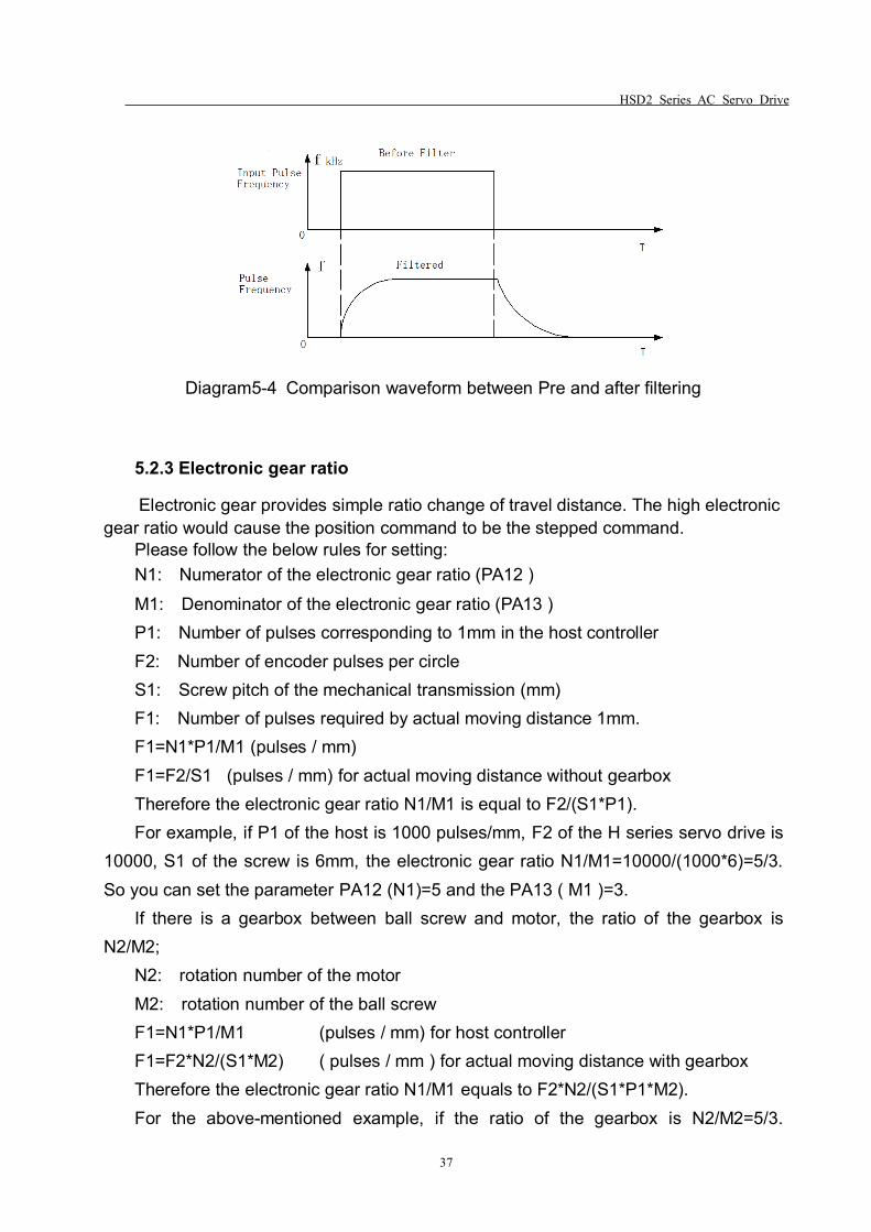
Filter for position control
The filter is designed to smooth the motion command. You can set parameter PA19to to achieve pulse filtering under the following circumstances: when the host controllerdoesn’t have accelerate or decelerate function, electronic gear ratio set value being toohigh; system load inertia being high or command frequency value is low. By using thepulse filter, you can have a more stable and smooth pulse frequency, avoid positioncommand lose, however, this performance will delay command reactions. WhenPA19=0,it means the filter is being disabled. This parameter indicates the time forposition frequency varies from 0-63% of the external pulse frequency. The pre and afterfiltering diagram comparison, please refer to the following Diagram 5-4.
HSD2 Series AC Servo Drive
37
Diagram5-4 Comparison waveform between Pre and after filtering
5.2.3 Electronic gear ratio
Electronic gear provides simple ratio change of travel distance. The high electronicgear ratio would cause the position command to be the stepped command.
Please follow the below rules for setting:N1: Numerator of the electronic gear ratio (PA12 )M1: Denominator of the electronic gear ratio (PA13 )P1: Number of pulses corresponding to 1mm in the host controllerF2: Number of encoder pulses per circleS1: Screw pitch of the mechanical transmission (mm)F1: Number of pulses required by actual moving distance 1mm.F1=N1*P1/M1 (pulses / mm)F1=F2/S1 (pulses / mm) for actual moving distance without gearboxTherefore the electronic gear ratio N1/M1 is equal to F2/(S1*P1).For example, if P1 of the host is 1000 pulses/mm, F2 of the H series servo drive is
10000, S1 of the screw is 6mm, the electronic gear ratio N1/M1=10000/(1000*6)=5/3.So you can set the parameter PA12 (N1)=5 and the PA13 ( M1 )=3.
If there is a gearbox between ball screw and motor, the ratio of the gearbox isN2/M2;
N2: rotation number of the motorM2: rotation number of the ball screwF1=N1*P1/M1 (pulses / mm) for host controllerF1=F2*N2/(S1*M2) ( pulses / mm ) for actual moving distance with gearboxTherefore the electronic gear ratio N1/M1 equals to F2*N2/(S1*P1*M2).For the above-mentioned example, if the ratio of the gearbox is N2/M2=5/3.
HSD2 Series AC Servo Drive
38
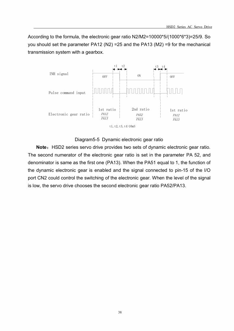
According to the formula, the electronic gear ratio N2/M2=10000*5/(1000*6*3)=25/9. Soyou should set the parameter PA12 (N2) =25 and the PA13 (M2) =9 for the mechanicaltransmission system with a gearbox.
t1 t2
OFF ON OFF
1st ratio 2nd ratio 1st ratioPA12
PA13PA52
PA13PA12
PA13
t1,t2,t3,t4>10mS
INH signal
Pulse command input
Electronic gear ratio
t3 t4
Diagram5-5 Dynamic electronic gear ratioNote:HSD2 series servo drive provides two sets of dynamic electronic gear ratio.
The second numerator of the electronic gear ratio is set in the parameter PA 52, anddenominator is same as the first one (PA13). When the PA51 equal to 1, the function ofthe dynamic electronic gear is enabled and the signal connected to pin-15 of the I/Oport CN2 could control the switching of the electronic gear. When the level of the signalis low, the servo drive chooses the second electronic gear ratio PA52/PA13.
HSD2 Series AC Servo Drive
39
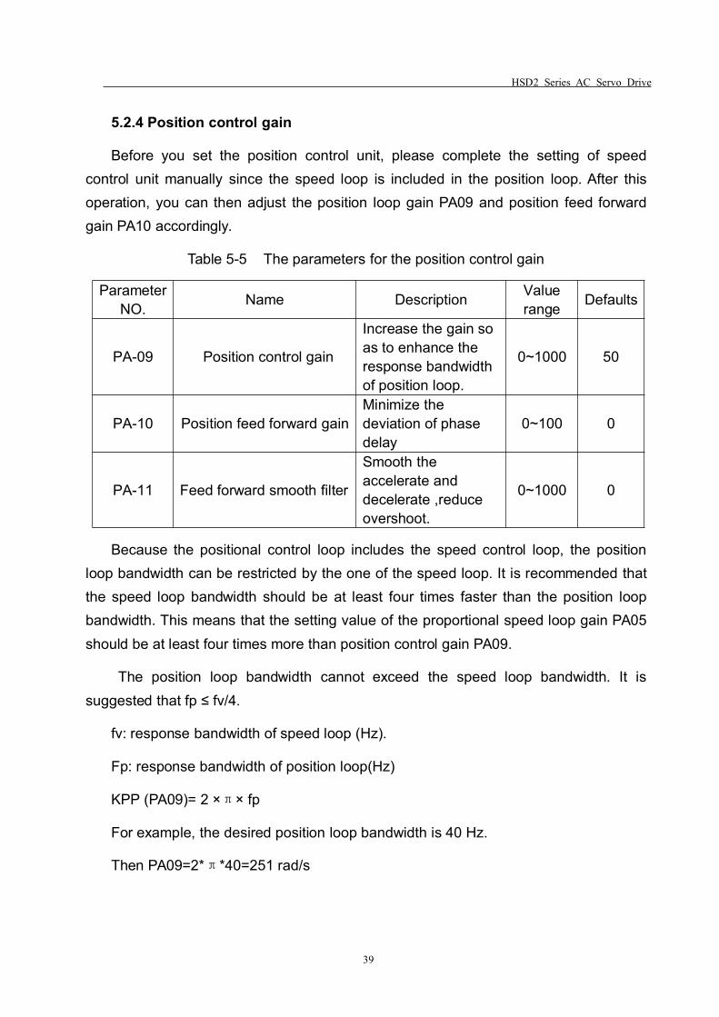
5.2.4 Position control gain
Before you set the position control unit, please complete the setting of speedcontrol unit manually since the speed loop is included in the position loop. After thisoperation, you can then adjust the position loop gain PA09 and position feed forwardgain PA10 accordingly.
Table 5-5 The parameters for the position control gain
ParameterNO. Name Description Value
range Defaults
PA-09 Position control gain
Increase the gain soas to enhance theresponse bandwidthof position loop.
0~1000 50
PA-10 Position feed forward gainMinimize thedeviation of phasedelay
0~100 0
PA-11 Feed forward smooth filter
Smooth theaccelerate anddecelerate ,reduceovershoot.
0~1000 0
Because the positional control loop includes the speed control loop, the positionloop bandwidth can be restricted by the one of the speed loop. It is recommended thatthe speed loop bandwidth should be at least four times faster than the position loopbandwidth. This means that the setting value of the proportional speed loop gain PA05should be at least four times more than position control gain PA09.
The position loop bandwidth cannot exceed the speed loop bandwidth. It issuggested that fp ≤ fv/4.
fv: response bandwidth of speed loop (Hz).
Fp: response bandwidth of position loop(Hz)
KPP (PA09)= 2 ×π× fp
For example, the desired position loop bandwidth is 40 Hz.
Then PA09=2*π*40=251 rad/s
HSD2 Series AC Servo Drive
40
+-
++
Position feedforward gain PA-10
Smooth ConstantPA-11
Position loopproportional gain PA09
SpeedCommand
EncoderPositionCounter
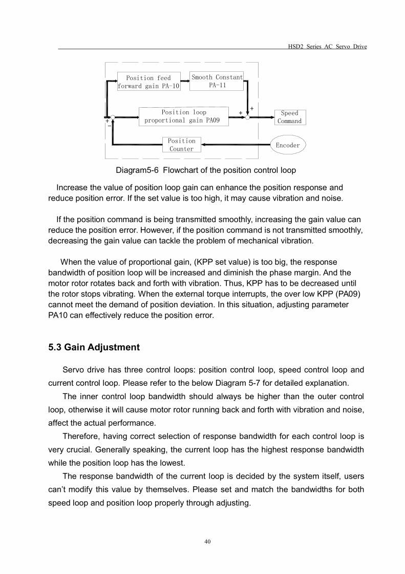
Diagram5-6 Flowchart of the position control loop
Increase the value of position loop gain can enhance the position response andreduce position error. If the set value is too high, it may cause vibration and noise.
If the position command is being transmitted smoothly, increasing the gain value canreduce the position error. However, if the position command is not transmitted smoothly,decreasing the gain value can tackle the problem of mechanical vibration.
When the value of proportional gain, (KPP set value) is too big, the responsebandwidth of position loop will be increased and diminish the phase margin. And themotor rotor rotates back and forth with vibration. Thus, KPP has to be decreased untilthe rotor stops vibrating. When the external torque interrupts, the over low KPP (PA09)cannot meet the demand of position deviation. In this situation, adjusting parameterPA10 can effectively reduce the position error.
5.3 Gain Adjustment
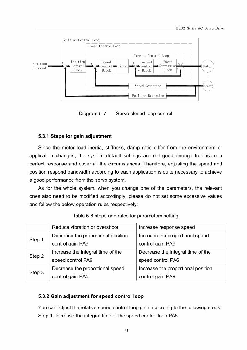
Servo drive has three control loops: position control loop, speed control loop andcurrent control loop. Please refer to the below Diagram 5-7 for detailed explanation.
The inner control loop bandwidth should always be higher than the outer controlloop, otherwise it will cause motor rotor running back and forth with vibration and noise,affect the actual performance.
Therefore, having correct selection of response bandwidth for each control loop isvery crucial. Generally speaking, the current loop has the highest response bandwidthwhile the position loop has the lowest.
The response bandwidth of the current loop is decided by the system itself, userscan’t modify this value by themselves. Please set and match the bandwidths for bothspeed loop and position loop properly through adjusting.
HSD2 Series AC Servo Drive
41
Position Control Loop
PositionControlBlock
Speed Detection
Speed Control Loop
SpeedControlBlock
Filter
Current Control Loop
CurrentControlBlock
PowerConversion
Block
+
-
+
-
+
-Motor
Encoder
Position Detection
PositionCommand
Diagram 5-7 Servo closed-loop control
5.3.1 Steps for gain adjustment
Since the motor load inertia, stiffness, damp ratio differ from the environment orapplication changes, the system default settings are not good enough to ensure aperfect response and cover all the circumstances. Therefore, adjusting the speed andposition respond bandwidth according to each application is quite necessary to achievea good performance from the servo system.
As for the whole system, when you change one of the parameters, the relevantones also need to be modified accordingly, please do not set some excessive valuesand follow the below operation rules respectively:
Table 5-6 steps and rules for parameters setting
Reduce vibration or overshoot Increase response speed
Step 1Decrease the proportional positioncontrol gain PA9
Increase the proportional speedcontrol gain PA9
Step 2Increase the integral time of thespeed control PA6
Decrease the integral time of thespeed control PA6
Step 3Decrease the proportional speedcontrol gain PA5
Increase the proportional positioncontrol gain PA9
5.3.2 Gain adjustment for speed control loop
You can adjust the relative speed control loop gain according to the following steps:Step 1: Increase the integral time of the speed control loop PA6
HSD2 Series AC Servo Drive
42
Step 2: Gradually increase the value of the proportional speed control loop gainPA5 setting without causing major vibration or noise ,if this does occur, pleasedecrease the gain setting value properly.
Step 3: Gradually decrease the integral time of the speed control loop PA6 until theresonance occurs, and then increase the setting value to eliminate the vibration.
Step 4: If the mechanical system resonates at a certain point, it’s impossible to geta very good system response performance. In this case, please adjust the torque valuePA7 for the low-pass filter to suppress the resonance, repeat the above steps toachieve a better response characteristic for the position and speed control loop.
5.3.3 Gain adjustment for position control loop
If the inertia of the machinery and conditions of applications is too high, and itcreates system resonance, you can adjust the relative parameters according to thefollowing steps:
Step 1: Increase the integral time of the speed control loop PA6
Step 2: Gradually increase the value of the proportional speed control loop gainPA5 setting without causing major vibration or noise ,if this does occur, pleasedecrease the gain setting value properly.
Step 3: Gradually decrease the integral time of the speed control loop PA6 until theresonance occurs, and then increase the setting value to eliminate the vibration.
Step 4: Gradually increase the value of proportional position loop gain until theresonance occurs, and then decrease the setting value to eliminate the vibration.
Step 5: If want to shorten position control time and minimise position error, you canadjust position feed forward gain PA10 and PA11 (the smooth constant of feed forwardgain) to achieve it.
Step 6: If the mechanical system resonates at a certain point, it’s impossible to geta very good system response performance. In this case, please adjust the torque valuePA7 for the low-pass filter to suppress the resonance, repeat the above steps toachieve a better response characteristic for the position and speed control loop.
5.4 Electromagnetic Brake
When operating brake via servo drive, if the digital output BRK is set to off, it
HSD2 Series AC Servo Drive
43
indicates that the electromagnetic brake is disabled and motor is locked. If the digitaloutput BRK is set to ON, it indicates electromagnetic brake is enabled and motor can beoperated. The electromagnetic brake is usually applied in Z-axis to reduce the largeenergy generated from servo motor. In order to avoid the brake error, it must be onwhen the servo drive if off. The brake has to be activated before the motor stopsrunning (Servo OFF). The brake has to be released after Servo ON. Otherwise, it wouldbecome the load of the motor and may damage the brake.
If the brakes is working during the process of acceleration or constant speed, theservo drive needs to generate more current to resist the force of brake and it may causethe alarm of overload warning.
5.4.1 Parameters of electromagnetic brake
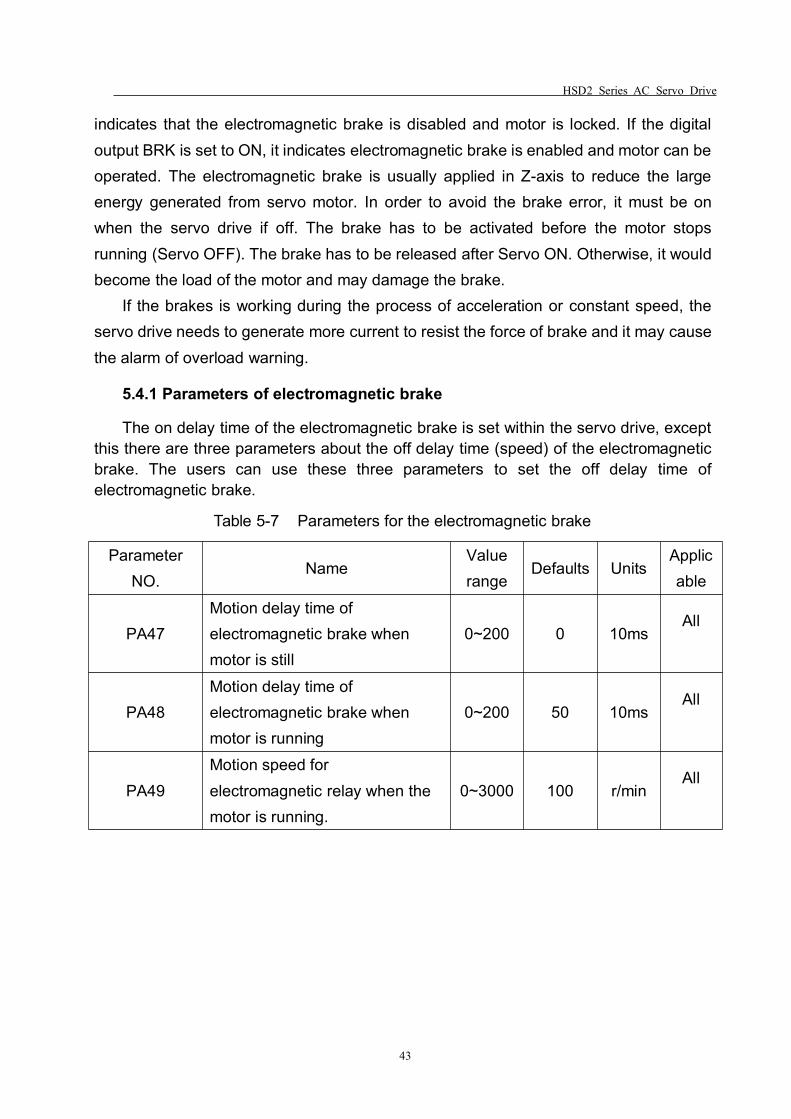
The on delay time of the electromagnetic brake is set within the servo drive, exceptthis there are three parameters about the off delay time (speed) of the electromagneticbrake. The users can use these three parameters to set the off delay time ofelectromagnetic brake.
Table 5-7 Parameters for the electromagnetic brake
ParameterNO.
NameValuerange
Defaults UnitsApplicable
PA47Motion delay time ofelectromagnetic brake whenmotor is still
0~200 0 10msAll
PA48Motion delay time ofelectromagnetic brake whenmotor is running
0~200 50 10msAll
PA49Motion speed forelectromagnetic relay when themotor is running.
0~3000 100 r/minAll
HSD2 Series AC Servo Drive
44
5.4.2 Wiring of electromagnetic brake
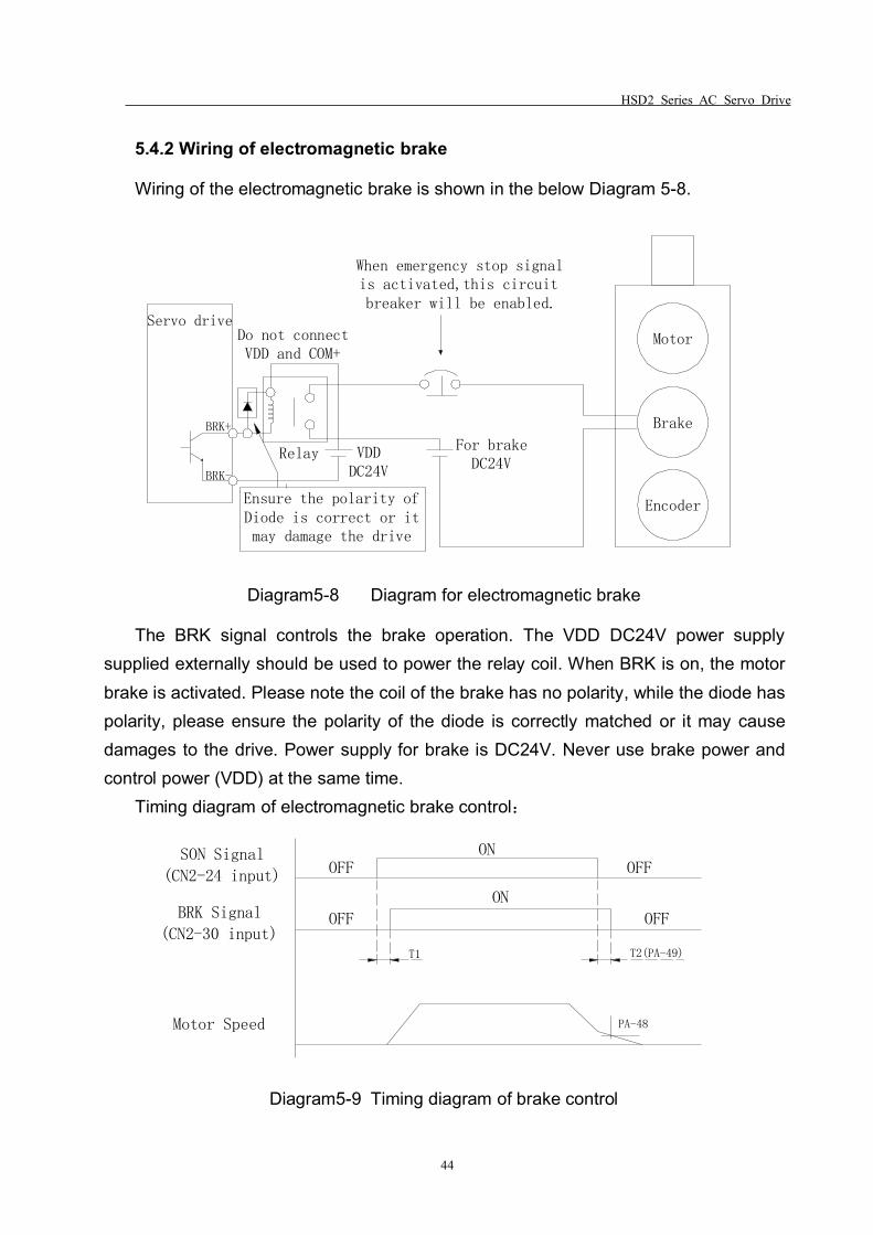
Wiring of the electromagnetic brake is shown in the below Diagram 5-8.
BRK+
BRK-
Ensure the polarity ofDiode is correct or itmay damage the drive
Relay VDDDC24V
For brakeDC24V
Do not connectVDD and COM+
When emergency stop signalis activated,this circuitbreaker will be enabled.
Motor
Brake
Encoder
Servo drive
Diagram5-8 Diagram for electromagnetic brake
The BRK signal controls the brake operation. The VDD DC24V power supplysupplied externally should be used to power the relay coil. When BRK is on, the motorbrake is activated. Please note the coil of the brake has no polarity, while the diode haspolarity, please ensure the polarity of the diode is correctly matched or it may causedamages to the drive. Power supply for brake is DC24V. Never use brake power andcontrol power (VDD) at the same time.
Timing diagram of electromagnetic brake control:
T1 T2(PA-49)
OFF
ON
ONOFF
OFF
OFF
PA-48
SON Signal
(CN2-24 input)
BRK Signal
(CN2-30 input)
Motor Speed
Diagram5-9 Timing diagram of brake control
HSD2 Series AC Servo Drive
45
BRK output timing explanation:1. when servo off ( when DI SON is not activated), the BRK output goes off
(electromagnetic brake is locked ) after the delay time set by PA48 reached and themotor speed is still higher than the setting value of PA49.
2. when servo off ( when DI SON is not activated), the BRK output goes off(electromagnetic brake is locked ) if the delay time set by PA48 has not reached but themotor speed is still lower than the setting value of PA49.
5.5 Timing
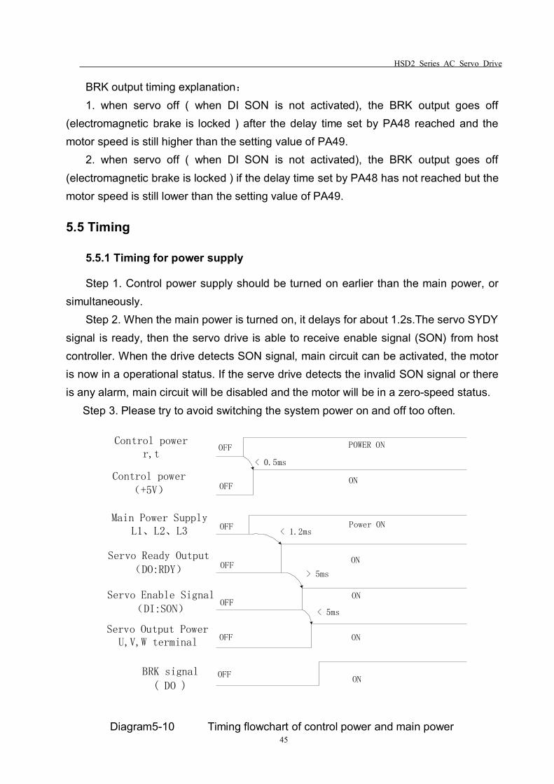
5.5.1 Timing for power supply
Step 1. Control power supply should be turned on earlier than the main power, orsimultaneously.
Step 2. When the main power is turned on, it delays for about 1.2s.The servo SYDYsignal is ready, then the servo drive is able to receive enable signal (SON) from hostcontroller. When the drive detects SON signal, main circuit can be activated, the motoris now in a operational status. If the serve drive detects the invalid SON signal or thereis any alarm, main circuit will be disabled and the motor will be in a zero-speed status.
Step 3. Please try to avoid switching the system power on and off too often.
Control powerr,t
Control power(+5V)
Main Power SupplyL1、L2、L3
Servo Ready Output(DO:RDY)
Servo Enable Signal(DI:SON)
Servo Output PowerU,V,W terminal
BRK signal
( DO )
OFF POWER ON
OFFON
OFF Power ON
OFF
OFF
OFF
OFF
ON
ON
ON
ON
< 0.5ms
< 1.2ms
> 5ms
< 5ms
Diagram5-10 Timing flowchart of control power and main power
HSD2 Series AC Servo Drive
46
Note:Even if the host controller output the SON signal before the SRDY signal ofthe drive, the servo drive couldn’t receive the SON until the SRDY signal is ON for 5 ms.
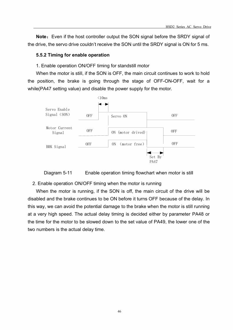
5.5.2 Timing for enable operation
1. Enable operation ON/OFF timing for standstill motorWhen the motor is still, if the SON is OFF, the main circuit continues to work to hold
the position, the brake is going through the stage of OFF-ON-OFF, wait for awhile(PA47 setting value) and disable the power supply for the motor.
Servo Enable
Signal(SON)
BRK Signal
Motor Current Signal
OFF OFF
OFF
Servo ON
ON (motor free) OFF
ON (motor drived)OFF OFF
<10ms
Set ByPA47
Diagram 5-11 Enable operation timing flowchart when motor is still
2. Enable operation ON/OFF timing when the motor is runningWhen the motor is running, if the SON is off, the main circuit of the drive will be
disabled and the brake continues to be ON before it turns OFF because of the delay. Inthis way, we can avoid the potential damage to the brake when the motor is still runningat a very high speed. The actual delay timing is decided either by parameter PA48 orthe time for the motor to be slowed down to the set value of PA49, the lower one of thetwo numbers is the actual delay time.
HSD2 Series AC Servo Drive
47
Motor speed
(r/min)
PA49
OFFON
ON
( motor drived )
OFF
Power OFF
0r/min
PA48
Servo Enable
Signal(SON)
Motor Current Signal
BRK Signal ON (motor free)
Diagram5-12 Disable operation timing flowchart when motor is running
5.5.3 Servo enable & servo alarm flowchart
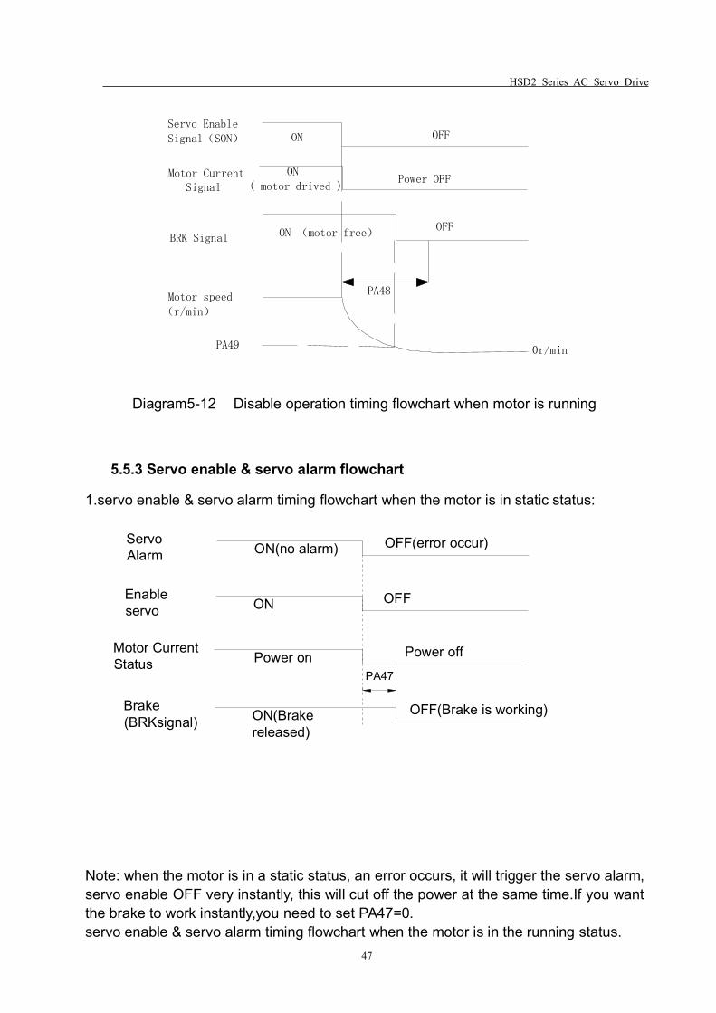
1.servo enable & servo alarm timing flowchart when the motor is in static status:
ON(no alarm) OFF(error occur)
ON OFFEnableservo
Power on Power offMotor CurrentStatus
ON(Brakereleased)
OFF(Brake is working)Brake(BRKsignal)
PA47
ServoAlarm
Note: when the motor is in a static status, an error occurs, it will trigger the servo alarm,servo enable OFF very instantly, this will cut off the power at the same time.If you wantthe brake to work instantly,you need to set PA47=0.servo enable & servo alarm timing flowchart when the motor is in the running status.
HSD2 Series AC Servo Drive
48
ServoAlarm ON(no alrm) OFF(error occur)
Enable servoON OFF
motor currentstatus Power
on
Power off
Brake(BRKsignal)
ON(Brakerelease)
OFF(Brake is working)reach PA49 setspeed or PA48 settime
PA49 set speed
Motor speedr/min
PA48
Note: when the motor is in a running status and there is an error and it triggered theservo alarm, servo enable will be off very instantly, power will be cut off at the sametime.The motor may be running at a high speed when the alarm triggers, in this case, ifthe brake is enabled to stop the motor at a high speed, it may damage thebrake.Therefore, we have PA48 and PA49 two parameters to avoid the potentialdamage.PA48 is the brake response delay time, PA49 is the set motor speed for thebrake to enable.The brake will work if one of these parameters reached it’s set value.If the motor is applied on the vertical axis of the equipment/machine, and it doesn’tallow any degree of free-fall of the motor, set PA48=0,and the brake will be workingstraight after the alarm triggered.If the applied equipment can allow a certain distance of free-fall for the motor, you canset proper values for PA48 & PA49, the brake will be enabled until the motor speedslows down to a certain degree(PA49 set value).During the speed slowdown process,the power is in OFF status for the servo, the load inertia slows the motor down in thiscase. If the time for the motor to reach PA49 set point is longer than PA48, then once itpassed PA48 set time, brake enables.
5.6 Start & Stop
The drive start/stop characteristics is determined by many aspects, such as loadinertia, on/off frequency, the status of both the drive itself and servo motor.
HSD2 Series AC Servo Drive
49
5.6.1 On-off frequency and load inertia
When the servo drive is used in the applications which require high on-off frequency,please confirm whether the frequency is within the rated frequency range of “H” seriesservo drives before you connect the application. The frequency range is determined bythe motor type, the load inertia and the speed of the motor etc. Please refer to thedetailed information from Table 5-8.
Table 5-8 On-off frequency VS Load inertia
Inertia multiples On-off frequency and ACC/DEC timeJ≤3Jmotor f>100 /min; less than 70MsJ≤5Jmotor 60<f≤100 /min; less than 130MsJ>5Jmotor f≤60 /min; greater than 150Ms
Note: The above table only provides the on-off frequency in the general cases, thespecific circumstances will vary from the motor types and the load conditions.
5.6.2 Adjustment Method
When the load inertia is five times (or above) greater than the motor inertia, someerrors may occur, such as position overshoot, excessive position deviation and speedresponse fault, break abnormal etc.
Under the above situations, you can take relevant actions according to the followingsteps:
Step 1: Increase the value of PA5 properly.
Step 2: Decrease the value of PA9 in the meantime. Reduce the inner torquelimitation value PA36.
Step 3: Increase the value of the parameter PA40, PA41 and PA42. (ACC/DECtime content) along with the S-curve ACC/DEC time content.
Step 4. Increase the ACC/DEC time content of the host system.
You can also consider of selecting a bigger inertia motor to meet your requirement.
HSD2 Series AC Servo Drive
50
Chapter 6 Parameters
6.1 Parameter Summary
The defaults of the following parameter table is shown as an example of HSD2-030drive. The value of the parameters marked “*” may be different from other types.
In the table, Applicable Mode means that the parameter can play a role in a certaincontrol mode: P refers to position control mode, S refers to speed control mode, T refersto Torque control mode and ALL refers to all of the control mode(position, speed andtorque control mode).
Input password parameter PA0 =315, you are able to set all parameters except forPA1.You need to set password PA0 = 302 to do changes about PA1.
Table 6.1 Parameter List
No. Function DescriptionApplicabl
eMode
Range Default Unit
PA-0 Password ALL 1-1000 315PA-1 Motor Type Code ALL 20~200 53*PA-2 Software Version(read only) ALL 0~99999 3.85.19*PA-3 Initial Display Status ALL 0~19 0PA-4 Control Mode Selection ALL 0~5 0
PA-5Proportional Speed LoopGain
P,S 1~5000 280* Hz
PA-6 Speed Integral Time P,S 1~1000 30* msPA-7 Torque filter ALL 0~1000 10 0.1msPA-8 Speed Detection Filter ALL 1~1000 10 0.1ms
PA-9Proportional Position LoopGain
P 1~1000 100 Hz
PA-10 Position Feed Forward Gain P 0~100 0 %
PA-11Smooth Constant of PositionFeed Forward Gain
P 0~1000 25 ms
PA-12Electronic Gear Ratio(Numerator) N1
P 1~30000 1
PA-13Electronic Gear Ratio(Denominator) M1
P 1~30000 1
PA-14 External Pulse Input Type P 0~2 0PA-15 Direction of External Pulse P 0~1 0
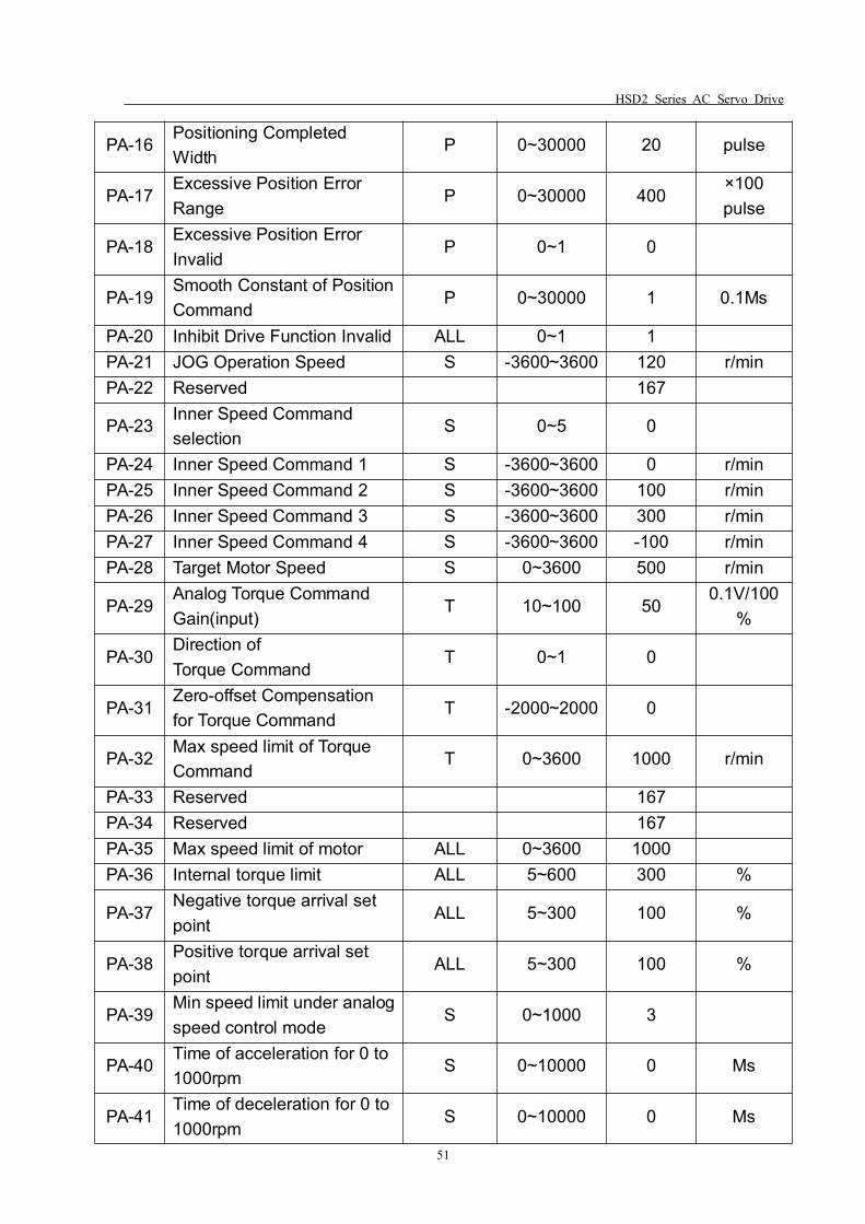
HSD2 Series AC Servo Drive
51
PA-16Positioning CompletedWidth
P 0~30000 20 pulse
PA-17Excessive Position ErrorRange
P 0~30000 400×100pulse
PA-18Excessive Position ErrorInvalid
P 0~1 0
PA-19Smooth Constant of PositionCommand
P 0~30000 1 0.1Ms
PA-20 Inhibit Drive Function Invalid ALL 0~1 1PA-21 JOG Operation Speed S -3600~3600 120 r/minPA-22 Reserved 167
PA-23Inner Speed Commandselection
S 0~5 0
PA-24 Inner Speed Command 1 S -3600~3600 0 r/minPA-25 Inner Speed Command 2 S -3600~3600 100 r/minPA-26 Inner Speed Command 3 S -3600~3600 300 r/minPA-27 Inner Speed Command 4 S -3600~3600 -100 r/minPA-28 Target Motor Speed S 0~3600 500 r/min
PA-29Analog Torque CommandGain(input)
T 10~100 500.1V/100
%
PA-30Direction ofTorque Command
T 0~1 0
PA-31Zero-offset Compensationfor Torque Command
T -2000~2000 0
PA-32Max speed limit of TorqueCommand
T 0~3600 1000 r/min
PA-33 Reserved 167PA-34 Reserved 167PA-35 Max speed limit of motor ALL 0~3600 1000PA-36 Internal torque limit ALL 5~600 300 %
PA-37Negative torque arrival setpoint
ALL 5~300 100 %
PA-38Positive torque arrival setpoint
ALL 5~300 100 %
PA-39Min speed limit under analogspeed control mode
S 0~1000 3
PA-40Time of acceleration for 0 to1000rpm
S 0~10000 0 Ms
PA-41Time of deceleration for 0 to1000rpm
S 0~10000 0 Ms
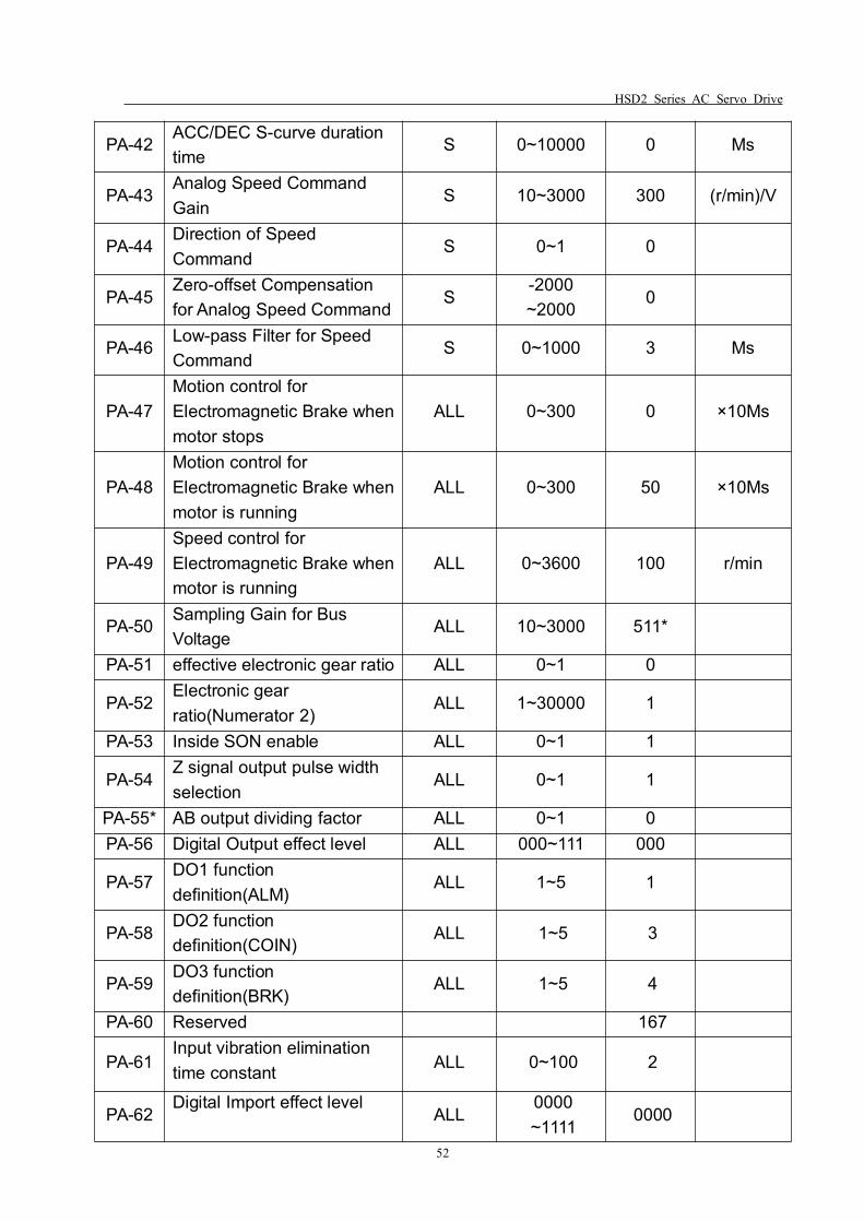
HSD2 Series AC Servo Drive
52
PA-42ACC/DEC S-curve durationtime
S 0~10000 0 Ms
PA-43Analog Speed CommandGain
S 10~3000 300 (r/min)/V
PA-44Direction of SpeedCommand
S 0~1 0
PA-45Zero-offset Compensationfor Analog Speed Command
S-2000~2000
0
PA-46Low-pass Filter for SpeedCommand
S 0~1000 3 Ms
PA-47Motion control forElectromagnetic Brake whenmotor stops
ALL 0~300 0 ×10Ms
PA-48Motion control forElectromagnetic Brake whenmotor is running
ALL 0~300 50 ×10Ms
PA-49Speed control forElectromagnetic Brake whenmotor is running
ALL 0~3600 100 r/min
PA-50Sampling Gain for BusVoltage
ALL 10~3000 511*
PA-51 effective electronic gear ratio ALL 0~1 0
PA-52Electronic gearratio(Numerator 2)
ALL 1~30000 1
PA-53 Inside SON enable ALL 0~1 1
PA-54Z signal output pulse widthselection
ALL 0~1 1
PA-55* AB output dividing factor ALL 0~1 0PA-56 Digital Output effect level ALL 000~111 000
PA-57DO1 functiondefinition(ALM)
ALL 1~5 1
PA-58DO2 functiondefinition(COIN)
ALL 1~5 3
PA-59DO3 functiondefinition(BRK)
ALL 1~5 4
PA-60 Reserved 167
PA-61Input vibration eliminationtime constant ALL 0~100 2
PA-62Digital Import effect level
ALL0000~1111
0000

HSD2 Series AC Servo Drive
53
PA-63 DI1 function definition(SON) ALL 1~7 1PA-64 DI2 function definition(CLE) ALL 1~7 2PA-65 DI3 function definition(SC2) ALL 1~7 3
PA-66DI4 functiondefinition(ALRS)
ALL 1~7 4
Note1: “*” next to the parameter numbers means this function may be “reserved” for some models, for
instance,PA-55*, it may not exist or reserved in some models, the detailed information, please consult with our after
sales service center or local distributors.
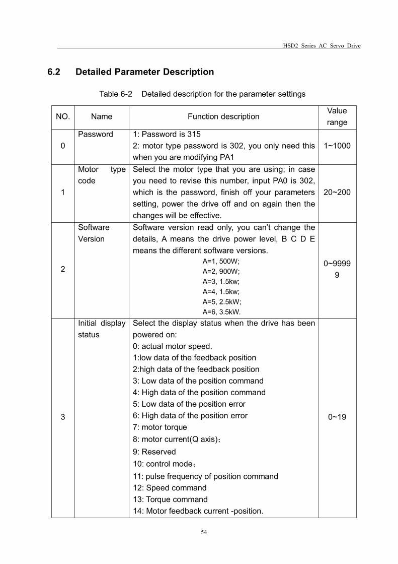
HSD2 Series AC Servo Drive
54
6.2 Detailed Parameter Description
Table 6-2 Detailed description for the parameter settings
NO. Name Function descriptionValuerange
0Password 1: Password is 315
2: motor type password is 302, you only need thiswhen you are modifying PA1
1~1000
1
Motor typecode
Select the motor type that you are using; in caseyou need to revise this number, input PA0 is 302,which is the password, finish off your parameterssetting, power the drive off and on again then thechanges will be effective.
20~200
2
SoftwareVersion
Software version read only, you can’t change thedetails, A means the drive power level, B C D Emeans the different software versions.
A=1, 500W;A=2, 900W;A=3, 1.5kw;A=4, 1.5kw;A=5, 2.5kW;A=6, 3.5kW.
0~99999
3
Initial displaystatus
Select the display status when the drive has beenpowered on:0: actual motor speed.1:low data of the feedback position2:high data of the feedback position3: Low data of the position command4: High data of the position command5: Low data of the position error6: High data of the position error7: motor torque8: motor current(Q axis);9: Reserved10: control mode;11: pulse frequency of position command12: Speed command13: Torque command14: Motor feedback current -position.
0~19
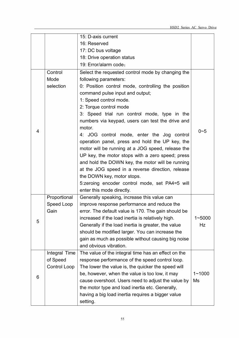
HSD2 Series AC Servo Drive
55
15: D-axis current16: Reserved17: DC bus voltage18: Drive operation status19: Error/alarm code;
4
ControlModeselection
Select the requested control mode by changing thefollowing parameters:0: Position control mode, controlling the positioncommand pulse input and output;1: Speed control mode.2: Torque control mode3: Speed trial run control mode, type in thenumbers via keypad, users can test the drive andmotor.4: JOG control mode, enter the Jog controloperation panel, press and hold the UP key, themotor will be running at a JOG speed, release theUP key, the motor stops with a zero speed; pressand hold the DOWN key, the motor will be runningat the JOG speed in a reverse direction, releasethe DOWN key, motor stops.5:zeroing encoder control mode, set PA4=5 willenter this mode directly.
0~5
5
ProportionalSpeed LoopGain
Generally speaking, increase this value canimprove response performance and reduce theerror. The default value is 170. The gain should beincreased if the load inertia is relatively high.Generally if the load inertia is greater, the valueshould be modified larger. You can increase thegain as much as possible without causing big noiseand obvious vibration.
1~5000Hz
6
Integral Timeof SpeedControl Loop
The value of the integral time has an effect on theresponse performance of the speed control loop.The lower the value is, the quicker the speed willbe, however, when the value is too low, it maycause overshoot. Users need to adjust the value bythe motor type and load inertia etc. Generally,having a big load inertia requires a bigger valuesetting.
1~1000Ms
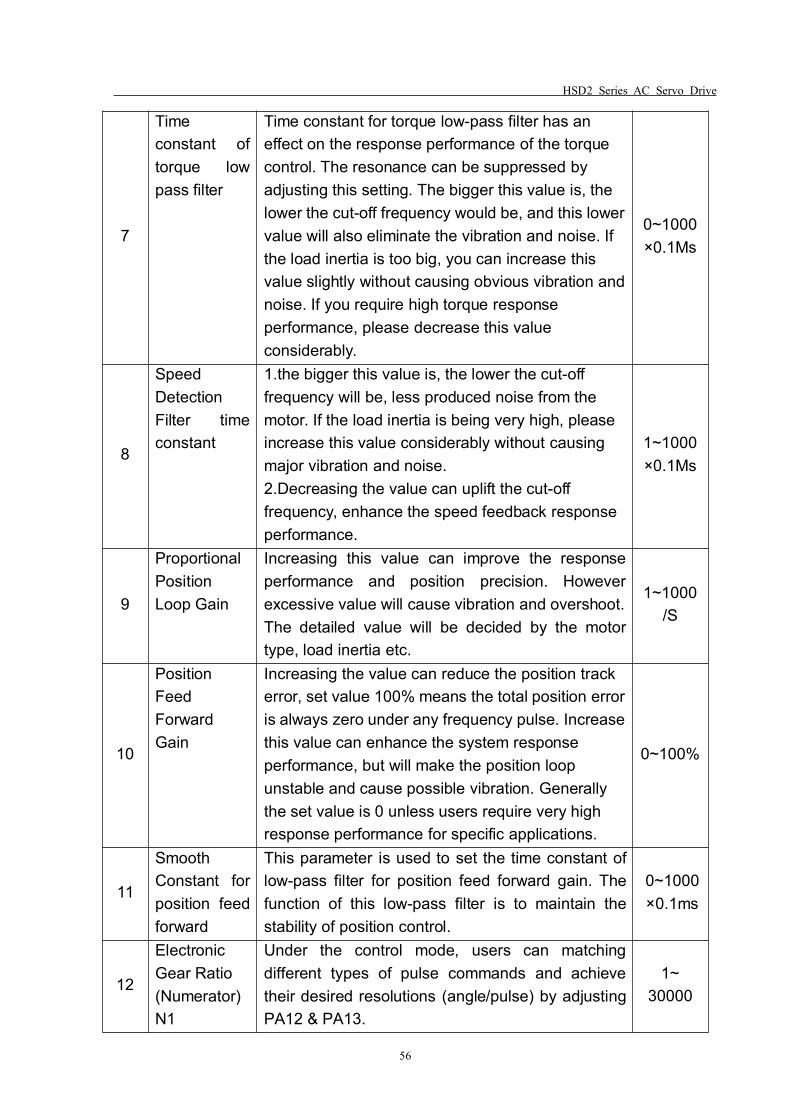
HSD2 Series AC Servo Drive
56
7
Timeconstant oftorque lowpass filter
Time constant for torque low-pass filter has aneffect on the response performance of the torquecontrol. The resonance can be suppressed byadjusting this setting. The bigger this value is, thelower the cut-off frequency would be, and this lowervalue will also eliminate the vibration and noise. Ifthe load inertia is too big, you can increase thisvalue slightly without causing obvious vibration andnoise. If you require high torque responseperformance, please decrease this valueconsiderably.
0~1000×0.1Ms
8
SpeedDetectionFilter timeconstant
1.the bigger this value is, the lower the cut-offfrequency will be, less produced noise from themotor. If the load inertia is being very high, pleaseincrease this value considerably without causingmajor vibration and noise.2.Decreasing the value can uplift the cut-offfrequency, enhance the speed feedback responseperformance.
1~1000×0.1Ms
9
ProportionalPositionLoop Gain
Increasing this value can improve the responseperformance and position precision. Howeverexcessive value will cause vibration and overshoot.The detailed value will be decided by the motortype, load inertia etc.
1~1000/S
10
PositionFeedForwardGain
Increasing the value can reduce the position trackerror, set value 100% means the total position erroris always zero under any frequency pulse. Increasethis value can enhance the system responseperformance, but will make the position loopunstable and cause possible vibration. Generallythe set value is 0 unless users require very highresponse performance for specific applications.
0~100%
11
SmoothConstant forposition feedforward
This parameter is used to set the time constant oflow-pass filter for position feed forward gain. Thefunction of this low-pass filter is to maintain thestability of position control.
0~1000×0.1ms
12
ElectronicGear Ratio(Numerator)N1
Under the control mode, users can matchingdifferent types of pulse commands and achievetheir desired resolutions (angle/pulse) by adjustingPA12 & PA13.
1~30000
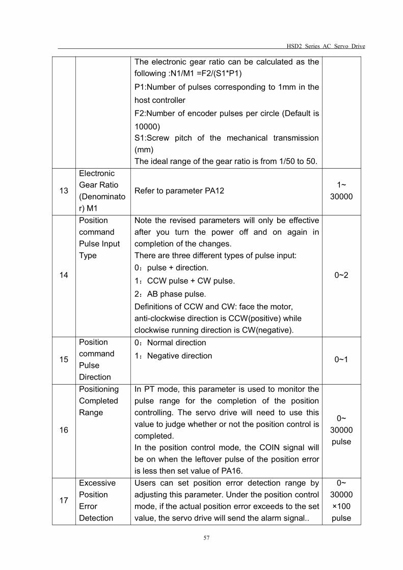
HSD2 Series AC Servo Drive
57
The electronic gear ratio can be calculated as thefollowing :N1/M1 =F2/(S1*P1)P1:Number of pulses corresponding to 1mm in thehost controllerF2:Number of encoder pulses per circle (Default is10000)S1:Screw pitch of the mechanical transmission(mm)The ideal range of the gear ratio is from 1/50 to 50.
13
ElectronicGear Ratio(Denominator) M1
Refer to parameter PA121~
30000
14
PositioncommandPulse InputType
Note the revised parameters will only be effectiveafter you turn the power off and on again incompletion of the changes.There are three different types of pulse input:0:pulse + direction.1:CCW pulse + CW pulse.2:AB phase pulse.Definitions of CCW and CW: face the motor,anti-clockwise direction is CCW(positive) whileclockwise running direction is CW(negative).
0~2
15
PositioncommandPulseDirection
0:Normal direction1:Negative direction 0~1
16
PositioningCompletedRange
In PT mode, this parameter is used to monitor thepulse range for the completion of the positioncontrolling. The servo drive will need to use thisvalue to judge whether or not the position control iscompleted.In the position control mode, the COIN signal willbe on when the leftover pulse of the position erroris less then set value of PA16.
0~30000pulse
17
ExcessivePositionErrorDetection
Users can set position error detection range byadjusting this parameter. Under the position controlmode, if the actual position error exceeds to the setvalue, the servo drive will send the alarm signal..
0~30000×100pulse
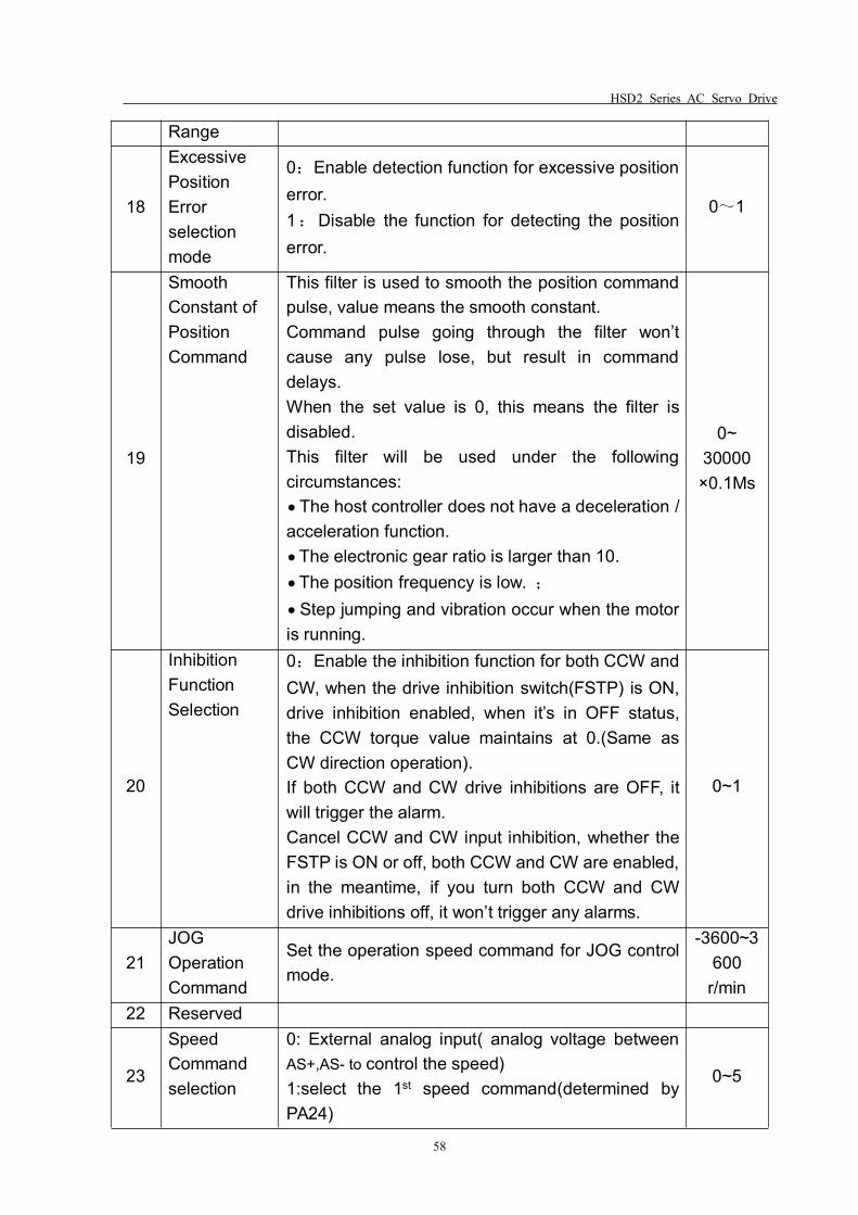
HSD2 Series AC Servo Drive
58
Range
18
ExcessivePositionErrorselectionmode
0:Enable detection function for excessive positionerror.1:Disable the function for detecting the positionerror.
0~1
19
SmoothConstant ofPositionCommand
This filter is used to smooth the position commandpulse, value means the smooth constant.Command pulse going through the filter won’tcause any pulse lose, but result in commanddelays.When the set value is 0, this means the filter isdisabled.This filter will be used under the followingcircumstances:The host controller does not have a deceleration /acceleration function.The electronic gear ratio is larger than 10.The position frequency is low. ;
Step jumping and vibration occur when the motoris running.
0~30000×0.1Ms
20
InhibitionFunctionSelection
0:Enable the inhibition function for both CCW andCW, when the drive inhibition switch(FSTP) is ON,drive inhibition enabled, when it’s in OFF status,the CCW torque value maintains at 0.(Same asCW direction operation).If both CCW and CW drive inhibitions are OFF, itwill trigger the alarm.Cancel CCW and CW input inhibition, whether theFSTP is ON or off, both CCW and CW are enabled,in the meantime, if you turn both CCW and CWdrive inhibitions off, it won’t trigger any alarms.
0~1
21JOGOperationCommand
Set the operation speed command for JOG controlmode.
-3600~3600
r/min22 Reserved
23
SpeedCommandselection
0: External analog input( analog voltage betweenAS+,AS- to control the speed)1:select the 1st speed command(determined byPA24)
0~5
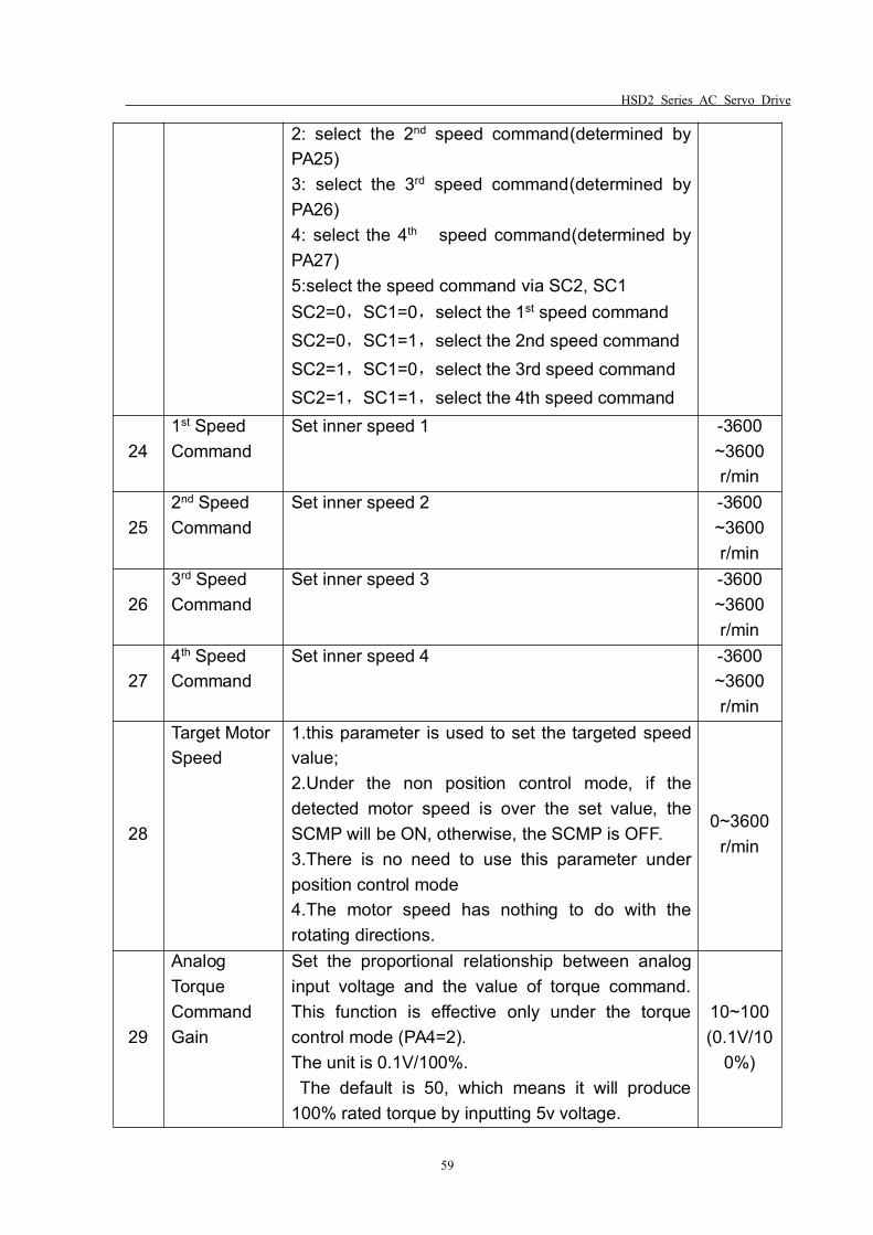
HSD2 Series AC Servo Drive
59
2: select the 2nd speed command(determined byPA25)3: select the 3rd speed command(determined byPA26)4: select the 4th speed command(determined byPA27)5:select the speed command via SC2, SC1SC2=0,SC1=0,select the 1st speed commandSC2=0,SC1=1,select the 2nd speed commandSC2=1,SC1=0,select the 3rd speed commandSC2=1,SC1=1,select the 4th speed command
241st SpeedCommand
Set inner speed 1 -3600~3600r/min
252nd SpeedCommand
Set inner speed 2 -3600~3600r/min
263rd SpeedCommand
Set inner speed 3 -3600~3600r/min
274th SpeedCommand
Set inner speed 4 -3600~3600r/min
28
Target MotorSpeed
1.this parameter is used to set the targeted speedvalue;2.Under the non position control mode, if thedetected motor speed is over the set value, theSCMP will be ON, otherwise, the SCMP is OFF.3.There is no need to use this parameter underposition control mode4.The motor speed has nothing to do with therotating directions.
0~3600r/min
29
AnalogTorqueCommandGain
Set the proportional relationship between analoginput voltage and the value of torque command.This function is effective only under the torquecontrol mode (PA4=2).The unit is 0.1V/100%.The default is 50, which means it will produce
100% rated torque by inputting 5v voltage.
10~100(0.1V/10
0%)
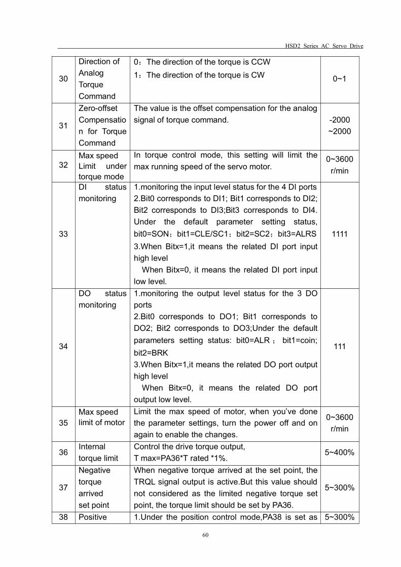
HSD2 Series AC Servo Drive
60
30
Direction ofAnalogTorqueCommand
0:The direction of the torque is CCW1:The direction of the torque is CW 0~1
31
Zero-offsetCompensation for TorqueCommand
The value is the offset compensation for the analogsignal of torque command. -2000
~2000
32Max speedLimit undertorque mode
In torque control mode, this setting will limit themax running speed of the servo motor.
0~3600r/min
33
DI statusmonitoring
1.monitoring the input level status for the 4 DI ports2.Bit0 corresponds to DI1; Bit1 corresponds to DI2;Bit2 corresponds to DI3;Bit3 corresponds to DI4.Under the default parameter setting status,bit0=SON;bit1=CLE/SC1;bit2=SC2;bit3=ALRS3.When Bitx=1,it means the related DI port inputhigh level
When Bitx=0, it means the related DI port inputlow level.
1111
34
DO statusmonitoring
1.monitoring the output level status for the 3 DOports2.Bit0 corresponds to DO1; Bit1 corresponds toDO2; Bit2 corresponds to DO3;Under the defaultparameters setting status: bit0=ALR ; bit1=coin;bit2=BRK3.When Bitx=1,it means the related DO port outputhigh level
When Bitx=0, it means the related DO portoutput low level.
111
35Max speedlimit of motor
Limit the max speed of motor, when you’ve donethe parameter settings, turn the power off and onagain to enable the changes.
0~3600r/min
36Internaltorque limit
Control the drive torque output,T max=PA36*T rated *1%.
5~400%
37
Negativetorquearrivedset point
When negative torque arrived at the set point, theTRQL signal output is active.But this value shouldnot considered as the limited negative torque setpoint, the torque limit should be set by PA36.
5~300%
38 Positive 1.Under the position control mode,PA38 is set as 5~300%
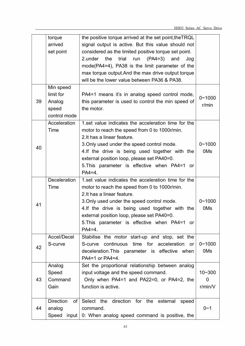
HSD2 Series AC Servo Drive
61
torquearrivedset point
the positive torque arrived at the set point,theTRQLsignal output is active. But this value should notconsidered as the limited positive torque set point.2.under the trial run (PA4=3) and Jogmode(PA4=4), PA38 is the limit parameter of themax torque output.And the max drive output torquewill be the lower value between PA36 & PA38.
39
Min speedlimit forAnalogspeedcontrol mode
PA4=1 means it’s in analog speed control mode,this parameter is used to control the min speed ofthe motor.
0~1000r/min
40
AccelerationTime
1.set value indicates the acceleration time for themotor to reach the speed from 0 to 1000r/min.2.It has a linear feature.3.Only used under the speed control mode.4.If the drive is being used together with theexternal position loop, please set PA40=0.5.This parameter is effective when PA4=1 orPA4=4.
0~10000Ms
41
DecelerationTime
1.set value indicates the acceleration time for themotor to reach the speed from 0 to 1000r/min.2.It has a linear feature.3.Only used under the speed control mode.4.If the drive is being used together with theexternal position loop, please set PA40=0.5.This parameter is effective when PA4=1 orPA4=4.
0~10000Ms
42
Accel/DecelS-curve
Stabilise the motor start-up and stop, set theS-curve continuous time for acceleration ordeceleration.This parameter is effective whenPA4=1 or PA4=4.
0~10000Ms
43
AnalogSpeedCommandGain
Set the proportional relationship between analoginput voltage and the speed command.Only when PA4=1 and PA22=0, or PA4=2, the
function is active.
10~3000
r/min/V
44Direction ofanalogSpeed input
Select the direction for the external speedcommand.0: When analog speed command is positive, the
0~1
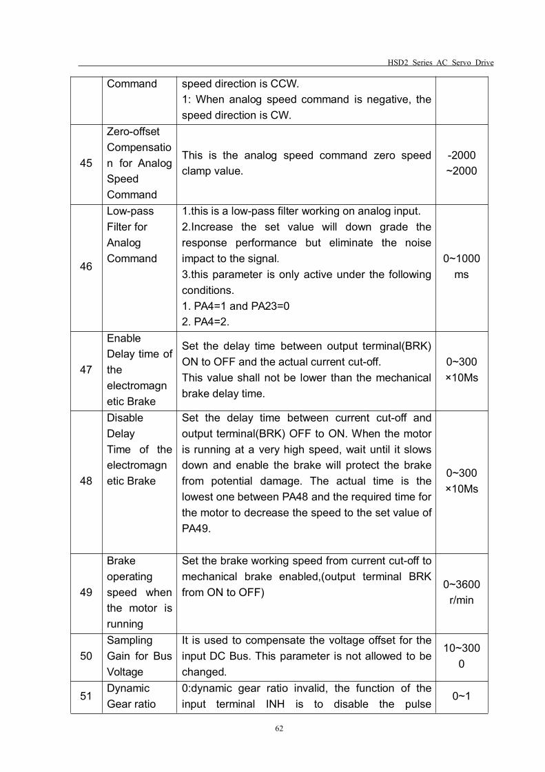
HSD2 Series AC Servo Drive
62
Command speed direction is CCW.1: When analog speed command is negative, thespeed direction is CW.
45
Zero-offsetCompensation for AnalogSpeedCommand
This is the analog speed command zero speedclamp value.
-2000~2000
46
Low-passFilter forAnalogCommand
1.this is a low-pass filter working on analog input.2.Increase the set value will down grade theresponse performance but eliminate the noiseimpact to the signal.3.this parameter is only active under the followingconditions.1. PA4=1 and PA23=02. PA4=2.
0~1000ms
47
EnableDelay time oftheelectromagnetic Brake
Set the delay time between output terminal(BRK)ON to OFF and the actual current cut-off.This value shall not be lower than the mechanicalbrake delay time.
0~300×10Ms
48
DisableDelayTime of theelectromagnetic Brake
Set the delay time between current cut-off andoutput terminal(BRK) OFF to ON. When the motoris running at a very high speed, wait until it slowsdown and enable the brake will protect the brakefrom potential damage. The actual time is thelowest one between PA48 and the required time forthe motor to decrease the speed to the set value ofPA49.
0~300×10Ms
49
Brakeoperatingspeed whenthe motor isrunning
Set the brake working speed from current cut-off tomechanical brake enabled,(output terminal BRKfrom ON to OFF)
0~3600r/min
50SamplingGain for BusVoltage
It is used to compensate the voltage offset for theinput DC Bus. This parameter is not allowed to bechanged.
10~3000
51DynamicGear ratio
0:dynamic gear ratio invalid, the function of theinput terminal INH is to disable the pulse
0~1
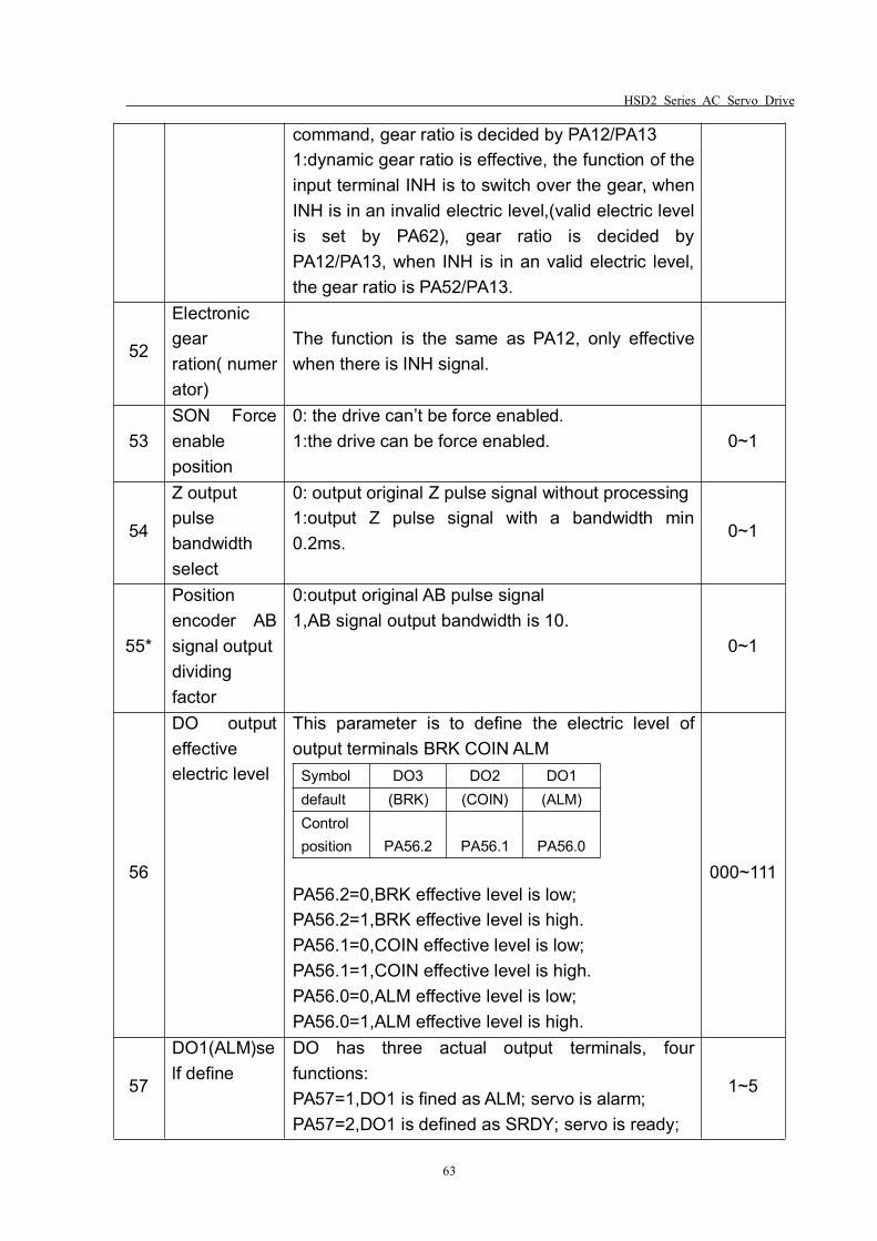
HSD2 Series AC Servo Drive
63
command, gear ratio is decided by PA12/PA131:dynamic gear ratio is effective, the function of theinput terminal INH is to switch over the gear, whenINH is in an invalid electric level,(valid electric levelis set by PA62), gear ratio is decided byPA12/PA13, when INH is in an valid electric level,the gear ratio is PA52/PA13.
52
Electronicgearration( numerator)
The function is the same as PA12, only effectivewhen there is INH signal.
53SON Forceenableposition
0: the drive can’t be force enabled.1:the drive can be force enabled. 0~1
54
Z outputpulsebandwidthselect
0: output original Z pulse signal without processing1:output Z pulse signal with a bandwidth min0.2ms.
0~1
55*
Positionencoder ABsignal outputdividingfactor
0:output original AB pulse signal1,AB signal output bandwidth is 10.
0~1
56
DO outputeffectiveelectric level
This parameter is to define the electric level ofoutput terminals BRK COIN ALM
Symbol DO3 DO2 DO1default (BRK) (COIN) (ALM)Controlposition PA56.2 PA56.1 PA56.0
PA56.2=0,BRK effective level is low;PA56.2=1,BRK effective level is high.PA56.1=0,COIN effective level is low;PA56.1=1,COIN effective level is high.PA56.0=0,ALM effective level is low;PA56.0=1,ALM effective level is high.
000~111
57
DO1(ALM)self define
DO has three actual output terminals, fourfunctions:PA57=1,DO1 is fined as ALM; servo is alarm;PA57=2,DO1 is defined as SRDY; servo is ready;
1~5
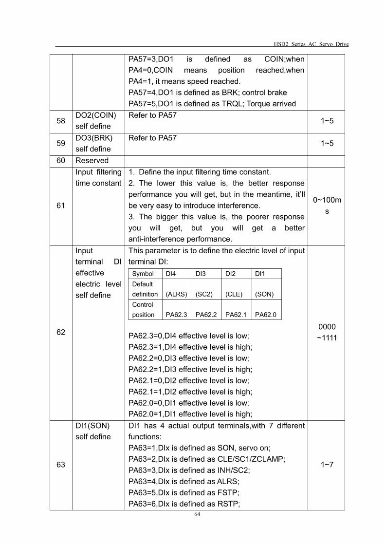
HSD2 Series AC Servo Drive
64
PA57=3,DO1 is defined as COIN;whenPA4=0,COIN means position reached,whenPA4=1, it means speed reached.PA57=4,DO1 is defined as BRK; control brakePA57=5,DO1 is defined as TRQL; Torque arrived
58DO2(COIN)self define
Refer to PA571~5
59DO3(BRK)self define
Refer to PA571~5
60 Reserved
61
Input filteringtime constant
1. Define the input filtering time constant.2. The lower this value is, the better responseperformance you will get, but in the meantime, it’llbe very easy to introduce interference.3. The bigger this value is, the poorer responseyou will get, but you will get a betteranti-interference performance.
0~100ms
62
Inputterminal DIeffectiveelectric levelself define
This parameter is to define the electric level of inputterminal DI:
Symbol DI4 DI3 DI2 DI1Defaultdefinition (ALRS) (SC2) (CLE) (SON)Controlposition PA62.3 PA62.2 PA62.1 PA62.0
PA62.3=0,DI4 effective level is low;PA62.3=1,DI4 effective level is high;PA62.2=0,DI3 effective level is low;PA62.2=1,DI3 effective level is high;PA62.1=0,DI2 effective level is low;PA62.1=1,DI2 effective level is high;PA62.0=0,DI1 effective level is low;PA62.0=1,DI1 effective level is high;
0000~1111
63
DI1(SON)self define
DI1 has 4 actual output terminals,with 7 differentfunctions:PA63=1,DIx is defined as SON, servo on;PA63=2,DIx is defined as CLE/SC1/ZCLAMP;PA63=3,DIx is defined as INH/SC2;PA63=4,DIx is defined as ALRS;PA63=5,DIx is defined as FSTP;PA63=6,DIx is defined as RSTP;
1~7
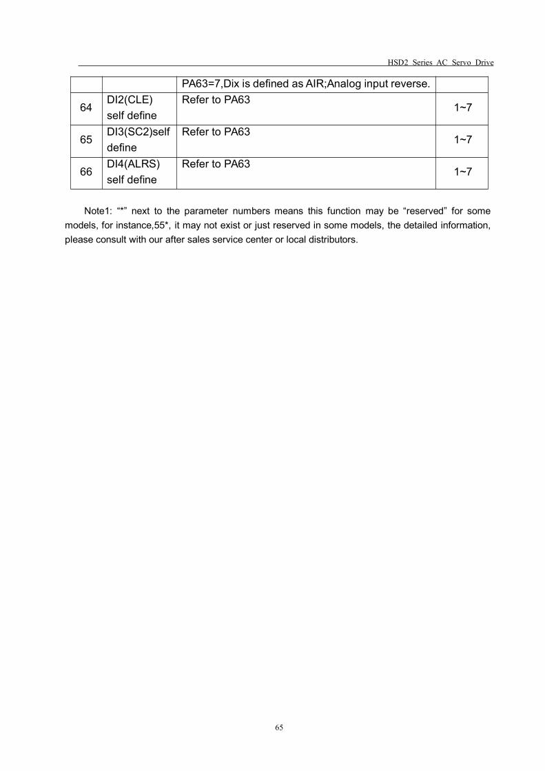
HSD2 Series AC Servo Drive
65
PA63=7,Dix is defined as AIR;Analog input reverse.
64DI2(CLE)self define
Refer to PA631~7
65DI3(SC2)selfdefine
Refer to PA631~7
66DI4(ALRS)self define
Refer to PA631~7
Note1: “*” next to the parameter numbers means this function may be “reserved” for somemodels, for instance,55*, it may not exist or just reserved in some models, the detailed information,please consult with our after sales service center or local distributors.
HSD2 Series AC Servo Drive
66
Chapter 7 Motor Type Matching
Before you power the servo drive, please make sure the motor is properly selectedand all parameters are set correctly, otherwise, it may cause malfunction, trigger thealarms off, or the motor may lose its control.
You need to input the password,(set PA0=302) before you modify the parameterPA1.
When you’ve done setting of PA1, please write(save) the parameters into servodrive(when the panel displays EE-SET, press the Enter key for 3 seconds until itdisplays ”FINISH”, this means the parameters are saved in the drive). Then power OFFand ON again, the set parameters will be effective.
Generally, please follow the following list when you are selecting the motor type:
Drive HSD2-020 is adaptive for 60, 80, 90, and 110 series motor.Drive HSD2-030/030A is adaptive for 80, 90, 110 and 130 series motor.Drive HSD2-050 is adaptive for 110, 130 and 150 series motor.Drive HSD2-065 is adaptive for 130, 150 and 180 series motor.
If client want to match other motors which is not produced by our company, pleaseconsult with your local distributor or our technical department.
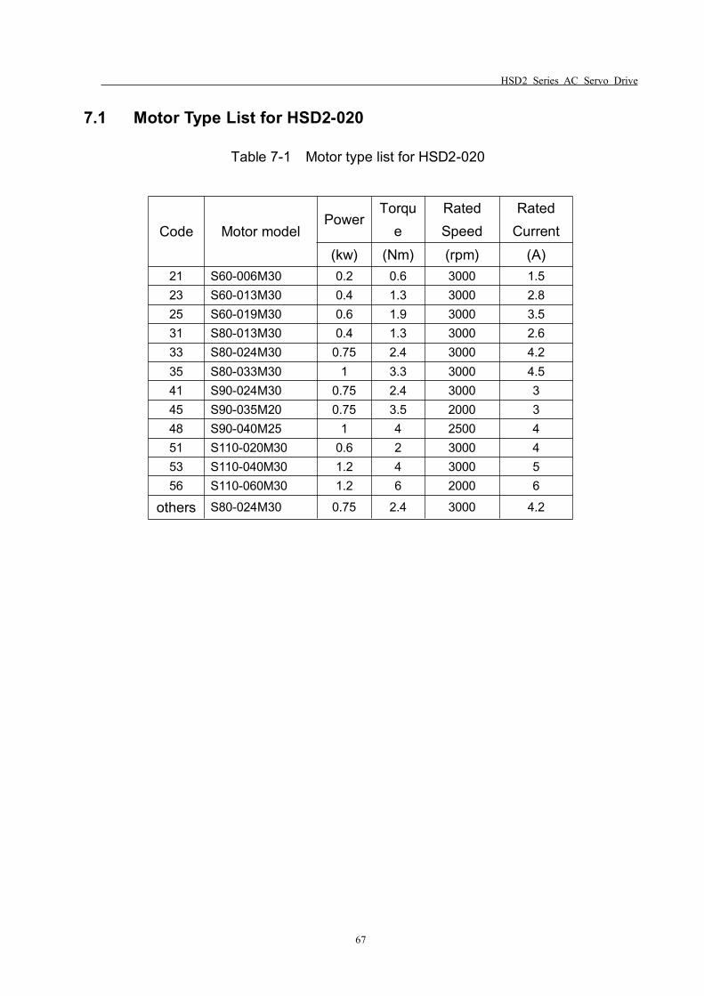
HSD2 Series AC Servo Drive
67
7.1 Motor Type List for HSD2-020
Table 7-1 Motor type list for HSD2-020
Code Motor modelPower
Torque
RatedSpeed
RatedCurrent
(kw) (Nm) (rpm) (A)21 S60-006M30 0.2 0.6 3000 1.523 S60-013M30 0.4 1.3 3000 2.825 S60-019M30 0.6 1.9 3000 3.531 S80-013M30 0.4 1.3 3000 2.633 S80-024M30 0.75 2.4 3000 4.235 S80-033M30 1 3.3 3000 4.541 S90-024M30 0.75 2.4 3000 345 S90-035M20 0.75 3.5 2000 348 S90-040M25 1 4 2500 451 S110-020M30 0.6 2 3000 453 S110-040M30 1.2 4 3000 556 S110-060M30 1.2 6 2000 6
others S80-024M30 0.75 2.4 3000 4.2
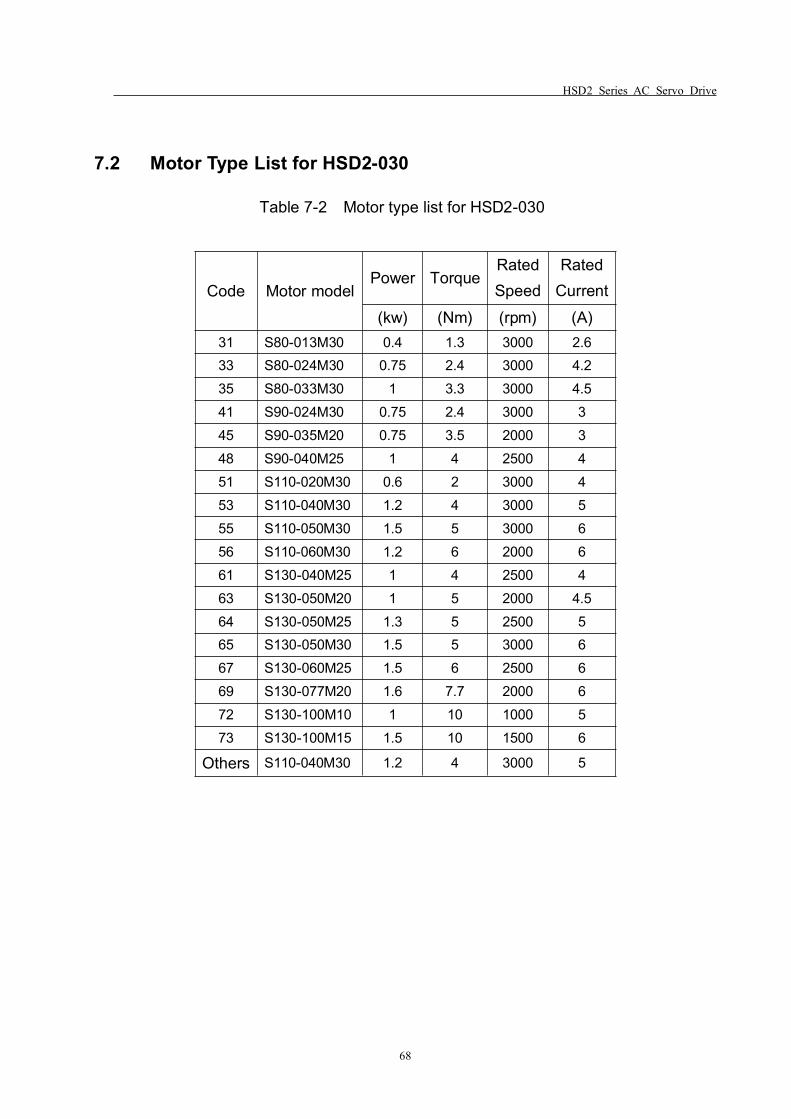
HSD2 Series AC Servo Drive
68
7.2 Motor Type List for HSD2-030
Table 7-2 Motor type list for HSD2-030
Code Motor modelPower Torque
RatedSpeed
RatedCurrent
(kw) (Nm) (rpm) (A)31 S80-013M30 0.4 1.3 3000 2.633 S80-024M30 0.75 2.4 3000 4.235 S80-033M30 1 3.3 3000 4.541 S90-024M30 0.75 2.4 3000 345 S90-035M20 0.75 3.5 2000 348 S90-040M25 1 4 2500 451 S110-020M30 0.6 2 3000 453 S110-040M30 1.2 4 3000 555 S110-050M30 1.5 5 3000 656 S110-060M30 1.2 6 2000 661 S130-040M25 1 4 2500 463 S130-050M20 1 5 2000 4.564 S130-050M25 1.3 5 2500 565 S130-050M30 1.5 5 3000 667 S130-060M25 1.5 6 2500 669 S130-077M20 1.6 7.7 2000 672 S130-100M10 1 10 1000 573 S130-100M15 1.5 10 1500 6
Others S110-040M30 1.2 4 3000 5
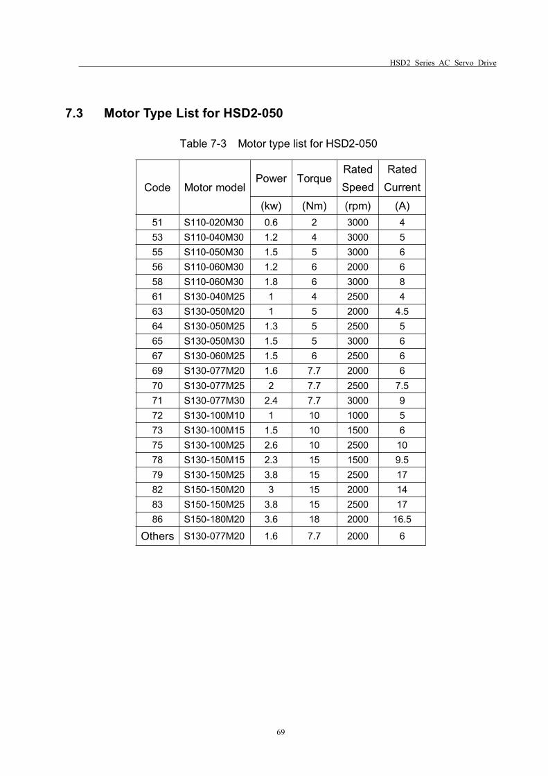
HSD2 Series AC Servo Drive
69
7.3 Motor Type List for HSD2-050
Table 7-3 Motor type list for HSD2-050
Code Motor modelPower Torque
RatedSpeed
RatedCurrent
(kw) (Nm) (rpm) (A)51 S110-020M30 0.6 2 3000 453 S110-040M30 1.2 4 3000 555 S110-050M30 1.5 5 3000 656 S110-060M30 1.2 6 2000 658 S110-060M30 1.8 6 3000 861 S130-040M25 1 4 2500 463 S130-050M20 1 5 2000 4.564 S130-050M25 1.3 5 2500 565 S130-050M30 1.5 5 3000 667 S130-060M25 1.5 6 2500 669 S130-077M20 1.6 7.7 2000 670 S130-077M25 2 7.7 2500 7.571 S130-077M30 2.4 7.7 3000 972 S130-100M10 1 10 1000 573 S130-100M15 1.5 10 1500 675 S130-100M25 2.6 10 2500 1078 S130-150M15 2.3 15 1500 9.579 S130-150M25 3.8 15 2500 1782 S150-150M20 3 15 2000 1483 S150-150M25 3.8 15 2500 1786 S150-180M20 3.6 18 2000 16.5
Others S130-077M20 1.6 7.7 2000 6
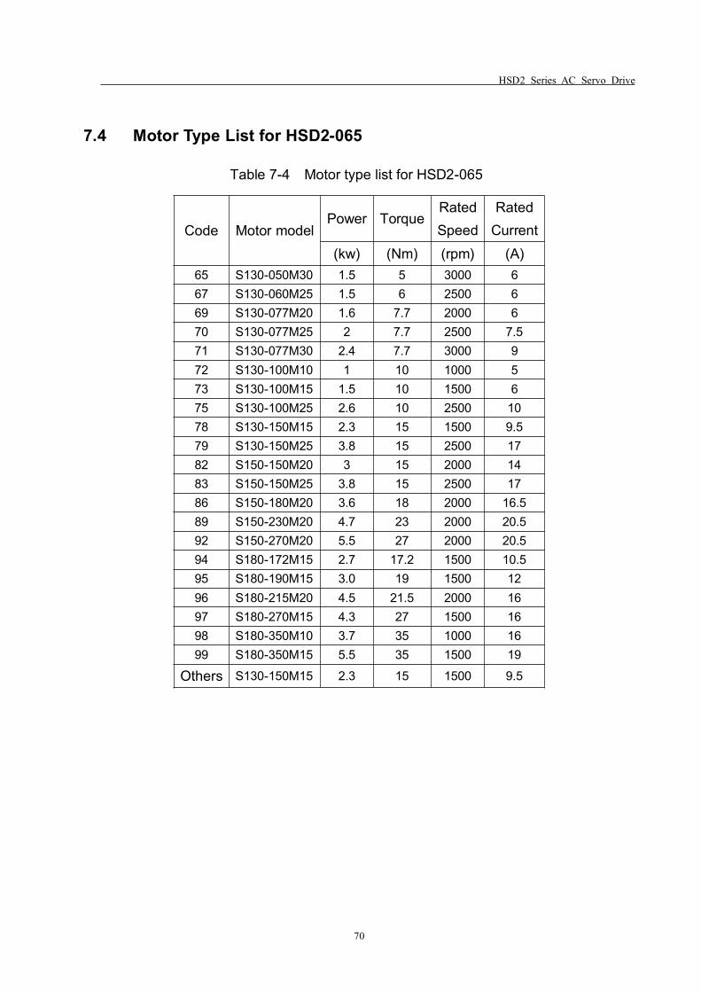
HSD2 Series AC Servo Drive
70
7.4 Motor Type List for HSD2-065
Table 7-4 Motor type list for HSD2-065
Code Motor modelPower Torque
RatedSpeed
RatedCurrent
(kw) (Nm) (rpm) (A)65 S130-050M30 1.5 5 3000 667 S130-060M25 1.5 6 2500 669 S130-077M20 1.6 7.7 2000 670 S130-077M25 2 7.7 2500 7.571 S130-077M30 2.4 7.7 3000 972 S130-100M10 1 10 1000 573 S130-100M15 1.5 10 1500 675 S130-100M25 2.6 10 2500 1078 S130-150M15 2.3 15 1500 9.579 S130-150M25 3.8 15 2500 1782 S150-150M20 3 15 2000 1483 S150-150M25 3.8 15 2500 1786 S150-180M20 3.6 18 2000 16.589 S150-230M20 4.7 23 2000 20.592 S150-270M20 5.5 27 2000 20.594 S180-172M15 2.7 17.2 1500 10.595 S180-190M15 3.0 19 1500 1296 S180-215M20 4.5 21.5 2000 1697 S180-270M15 4.3 27 1500 1698 S180-350M10 3.7 35 1000 1699 S180-350M15 5.5 35 1500 19
Others S130-150M15 2.3 15 1500 9.5
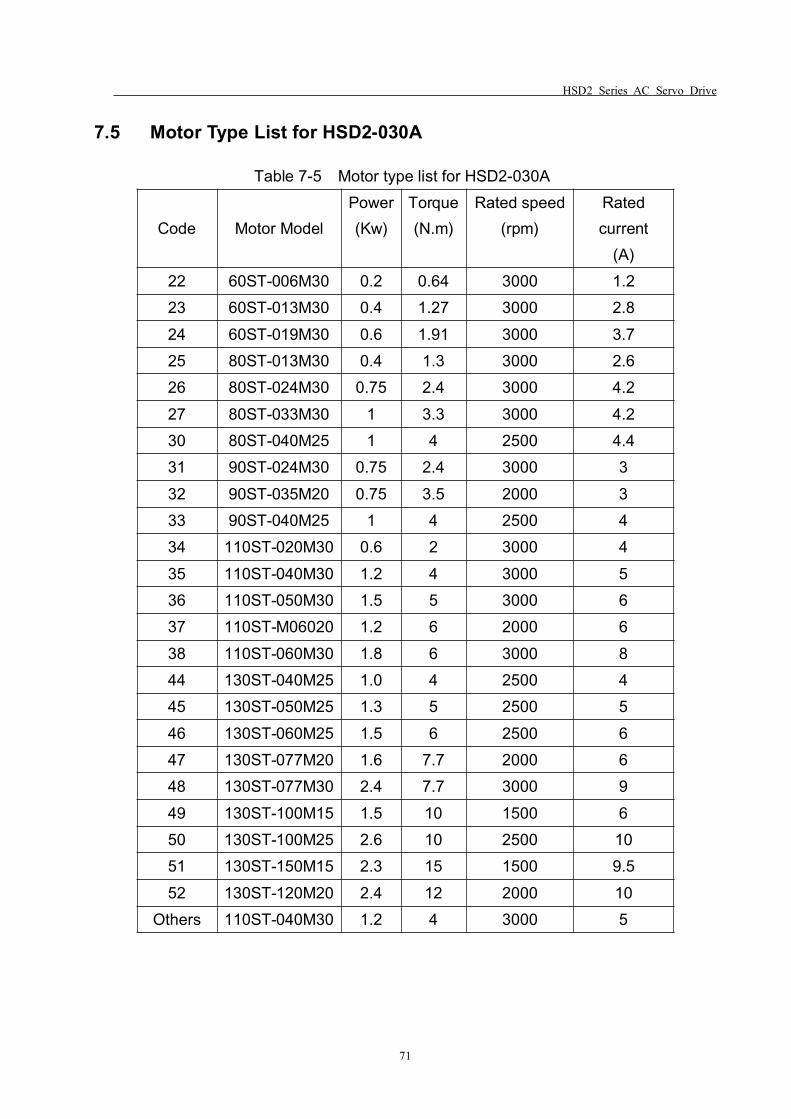
HSD2 Series AC Servo Drive
71
7.5 Motor Type List for HSD2-030A
Table 7-5 Motor type list for HSD2-030A
Code Motor ModelPower(Kw)
Torque(N.m)
Rated speed(rpm)
Ratedcurrent
(A)22 60ST-006M30 0.2 0.64 3000 1.223 60ST-013M30 0.4 1.27 3000 2.824 60ST-019M30 0.6 1.91 3000 3.725 80ST-013M30 0.4 1.3 3000 2.626 80ST-024M30 0.75 2.4 3000 4.227 80ST-033M30 1 3.3 3000 4.230 80ST-040M25 1 4 2500 4.431 90ST-024M30 0.75 2.4 3000 332 90ST-035M20 0.75 3.5 2000 333 90ST-040M25 1 4 2500 434 110ST-020M30 0.6 2 3000 435 110ST-040M30 1.2 4 3000 536 110ST-050M30 1.5 5 3000 637 110ST-M06020 1.2 6 2000 638 110ST-060M30 1.8 6 3000 844 130ST-040M25 1.0 4 2500 445 130ST-050M25 1.3 5 2500 546 130ST-060M25 1.5 6 2500 647 130ST-077M20 1.6 7.7 2000 648 130ST-077M30 2.4 7.7 3000 949 130ST-100M15 1.5 10 1500 650 130ST-100M25 2.6 10 2500 1051 130ST-150M15 2.3 15 1500 9.552 130ST-120M20 2.4 12 2000 10
Others 110ST-040M30 1.2 4 3000 5
HSD2 Series AC Servo Drive
72
Chapter 8 Alarm, Protection Function & Troubleshooting
When any trouble occurs, the “Err xx” would be shown on the digital keypad andblink. “xx” is the code for the error kind. The common errors are Err 3, Err 9, Err 11, Err13, Err 17 and Err 38, which caused by improper wiring or mechanical problem.
8.1 Alarm Code Check List
Table 8-1 Alarm code check list
DisplayCode
Fault Name Fault Description
- - Normal There is no error.1 Over speed Motor speed exceeds to set value
2 Over voltageThe voltage of the main circuit ishigher than the standard voltage.
3 Under voltageThe voltage of the main circuit islower than the standard voltage.
4Excessive Deviation ofposition command
Position control deviation value exceeds to theset value
5Internal incorrect parametersettings
Wrong model selection for servo drive ormotor, or wrong settings for drive/motor
6Wrong model type for themotor
The set model type can’t be matched with themotor
7 Drive inhibition error Both inhibition input for CCW and CW are OFF
8Position deviation counteroverflow
Position counter overflow absolute valueexceeds to 230
9 Encoder error The encoder produces abnormal pulse.
11 Current response faultCurrent error has exceeded the specified valuefor a long time.
12 Over currentThe current of the main circuit is more than theinstantaneous current of the motor and causeshort circuit.
13Drive overheat for a longtime
Drive overload, the temperature of drive is toohigh (I2t inspection)
14Breaking time being toolong
Break circuit is working for a long period oftime.
HSD2 Series AC Servo Drive
73
15Breaking function isenabled too often
The breaking action has been enabled toooften.
17 Speed response faultSpeed error has exceeded the specified valuefor a long time.
19 Warm reset System warm reset
20 EE-PROM errorAn error occurs when writing the currentsettings into EE-PROM.
21 DI function set error Digital input port function setting duplicated22 DO function set error Digital output port function setting duplicated
23Current sensor adjustmenterror
Adjusted value of the current sensor exceedsthe limit of its allowable setting value.
29 Overload for motor torque Servo motor is overload.30 Encoder pulse Z lose The pulse Z of the encoder is being lost.
32 Encoder U,V,W signal errorThe signal of U,V,W (for encoder interface) arein error
37Instantaneous overheat formotor
The instantaneous load of the motor isoverload.
38 Long term motor overheat The motor is overload for a long time.10, 16, 18, 24, 25, 26, 27, 28, 31, 33,34, 35, 36
Reserved
HSD2 Series AC Servo Drive
74
8.2 Potential Cause and Corrective Actions
Generally, when the alarm occurs, you can power off and on the drive to clear theerror, and the drive back to work normally. If this doesn’t work, and the alarm repeats,please follow up the following solutions or contact your local distributors if necessary.
Table 8-2 Corrective actions for trouble shooting
Code Fault Name Cause Corrective Actions
Err1 Over speed
Improper inputPulse, or wrong gear ratiosetting
Check the pulse frequency andthe electronic gear ratio
The load inertia isexcessive
Decrease the load inertia
Increase the Accel/Decel time
Encoder fault Replace the motor
Encoder cable fault Replace the cable
Incorrect parametersettings
Reset the parameters andmodify the settings again
Err2 Over voltage
Servo drive defaultU V W PE wiring error
Replace the drive; check thewiring or replace the cables
The power voltage is toohigh
Check the power supply.The power waveform isabnormal
Err3 Under voltage
Servo drive is damaged Replace the drive
The power voltage is toolow.
Check the power supply.
Transformer capacity is notenough.
Replace the transformer by alarger one
Poor contact of RSTterminal wiring
Check and rewire the relatedcables
Err4Excessiveposition deviation
Encoder cable or encoderfault
Replace the cable or motor
The stiffness is not enoughIncrease the set value of PA5and PA9
The output torque of motor Check the torque limit
HSD2 Series AC Servo Drive
75
Decrease the loadReplace and upgrade thepower level of the drive andmotor
Improper command pulse Decrease the pulse frequency.
Err5Parameters seterror
The parameters in thedrive is or are beingmodified wrongly
Reset the parameters
Err6Wrong modeltype setting forthe motor
Wrong model type settingfor the motor
Please choose the right motortype.
Err7Drive inhibitionabnormal alarm
Inhibition signal for bothCCW and CW aredisconnected
Check the digital input signaland wiring
Enable Inhibition functionis ON
Disable the function
Err8Position counteroverflow
The motor is being stuckby the mechanical parts
Check the mechanical structure
Pulse signal is abnormal Check the pulse signal
Err9 Encoder error
Encoder or drive beingdamaged
Replace the motor or drive.
Encoder cable damaged ordoesn’t match the spec
Replace the cable
The encoder cable is toolong
Shorten the cable.
Err11Current responsefault
Servo motor is being stuck. Check the mechanical parts
Wrong wring between U, Vand W terminals
Check the wiring
Poorly grounded Check the grounding
The lead wiring of U V Wfrom the motor side iswrong
Replace the motor
Err12 Over currentShort-circuit between U, Vand W terminals
Check the wiring
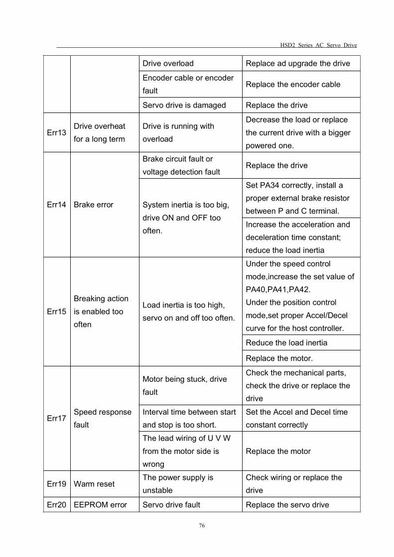
HSD2 Series AC Servo Drive
76
Drive overload Replace ad upgrade the drive
Encoder cable or encoderfault
Replace the encoder cable
Servo drive is damaged Replace the drive
Err13Drive overheatfor a long term
Drive is running withoverload
Decrease the load or replacethe current drive with a biggerpowered one.
Err14 Brake error
Brake circuit fault orvoltage detection fault
Replace the drive
System inertia is too big,drive ON and OFF toooften.
Set PA34 correctly, install aproper external brake resistorbetween P and C terminal.Increase the acceleration anddeceleration time constant;reduce the load inertia
Err15Breaking actionis enabled toooften
Load inertia is too high,servo on and off too often.
Under the speed controlmode,increase the set value ofPA40,PA41,PA42.Under the position controlmode,set proper Accel/Decelcurve for the host controller.
Reduce the load inertia
Replace the motor.
Err17Speed responsefault
Motor being stuck, drivefault
Check the mechanical parts,check the drive or replace thedrive
Interval time between startand stop is too short.
Set the Accel and Decel timeconstant correctly
The lead wiring of U V Wfrom the motor side iswrong
Replace the motor
Err19 Warm resetThe power supply isunstable
Check wiring or replace thedrive
Err20 EEPROM error Servo drive fault Replace the servo drive
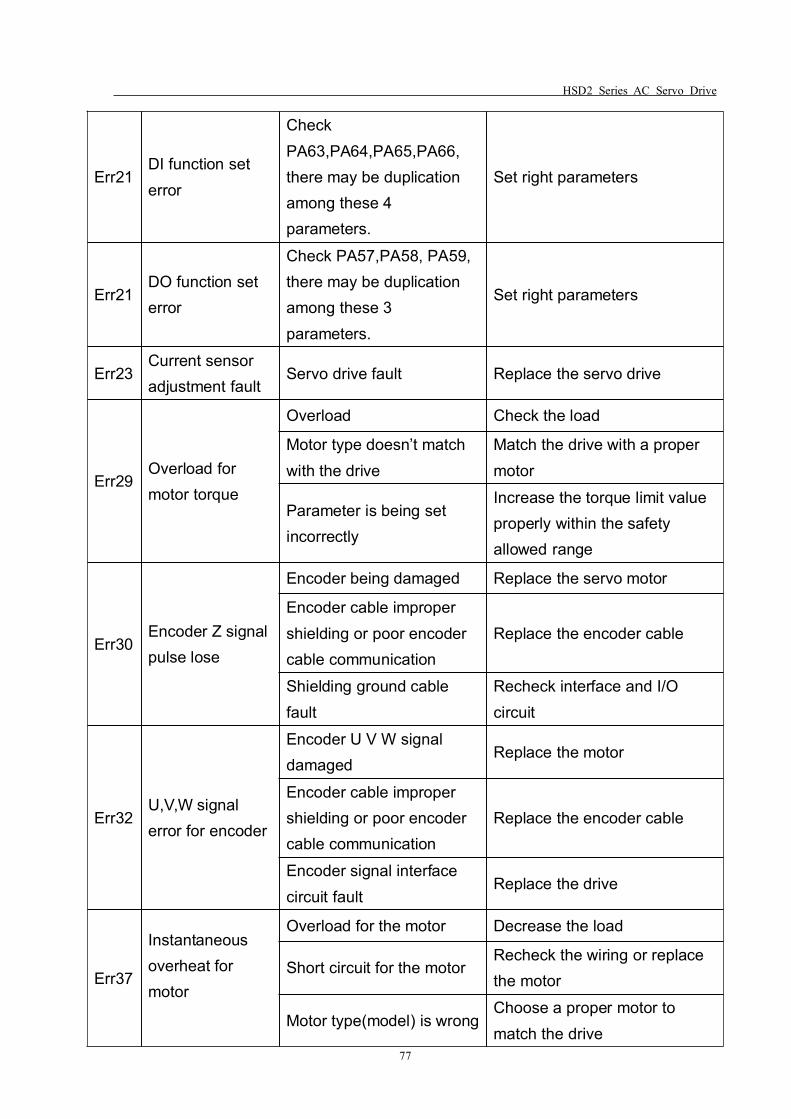
HSD2 Series AC Servo Drive
77
Err21DI function seterror
CheckPA63,PA64,PA65,PA66,there may be duplicationamong these 4parameters.
Set right parameters
Err21DO function seterror
Check PA57,PA58, PA59,there may be duplicationamong these 3parameters.
Set right parameters
Err23Current sensoradjustment fault
Servo drive fault Replace the servo drive
Err29Overload formotor torque
Overload Check the load
Motor type doesn’t matchwith the drive
Match the drive with a propermotor
Parameter is being setincorrectly
Increase the torque limit valueproperly within the safetyallowed range
Err30Encoder Z signalpulse lose
Encoder being damaged Replace the servo motor
Encoder cable impropershielding or poor encodercable communication
Replace the encoder cable
Shielding ground cablefault
Recheck interface and I/Ocircuit
Err32U,V,W signalerror for encoder
Encoder U V W signaldamaged
Replace the motor
Encoder cable impropershielding or poor encodercable communication
Replace the encoder cable
Encoder signal interfacecircuit fault
Replace the drive
Err37
Instantaneousoverheat formotor
Overload for the motor Decrease the load
Short circuit for the motorRecheck the wiring or replacethe motor
Motor type(model) is wrongChoose a proper motor tomatch the drive

HSD2 Series AC Servo Drive
78
Err38Motor overheatfor a long time
Motor overload, or wrongtype of motor beingconnected with the drive
Decrease the load or choose aproper spec of motor to matchthe drive
Encoder cable or encoderfault; drive currentdetection fault
Replace the encoder cable ormotor; replace the drive
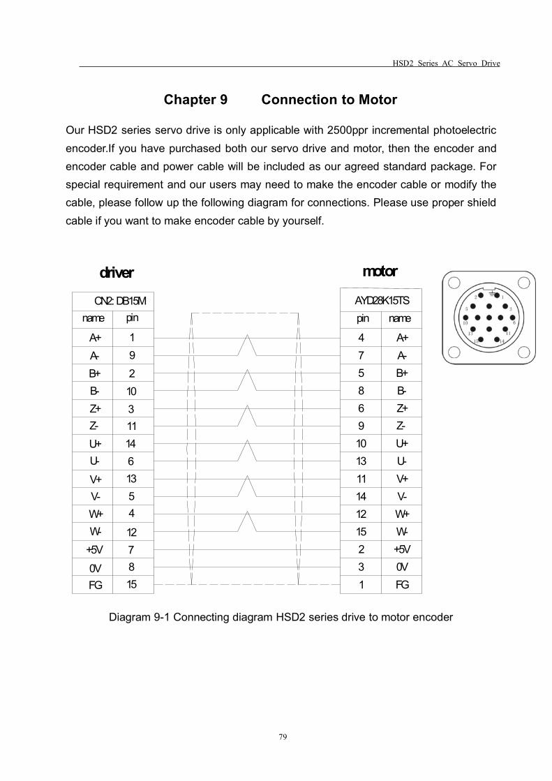
HSD2 Series AC Servo Drive
79
Chapter 9 Connection to Motor
Our HSD2 series servo drive is only applicable with 2500ppr incremental photoelectricencoder.If you have purchased both our servo drive and motor, then the encoder andencoder cable and power cable will be included as our agreed standard package. Forspecial requirement and our users may need to make the encoder cable or modify thecable, please follow up the following diagram for connections. Please use proper shieldcable if you want to make encoder cable by yourself.
192
103111461354
127815FG
0V+5VW-W+V-V+U-U+Z-Z+B-B+A-A+ 4
75869101311141215231
pinname
FG0V+5VW-W+V-V+U-U+Z-Z+B-B+A-A+
CN2: DB15M AYD28K15TSpin name
driver motor
Diagram 9-1 Connecting diagram HSD2 series drive to motor encoder
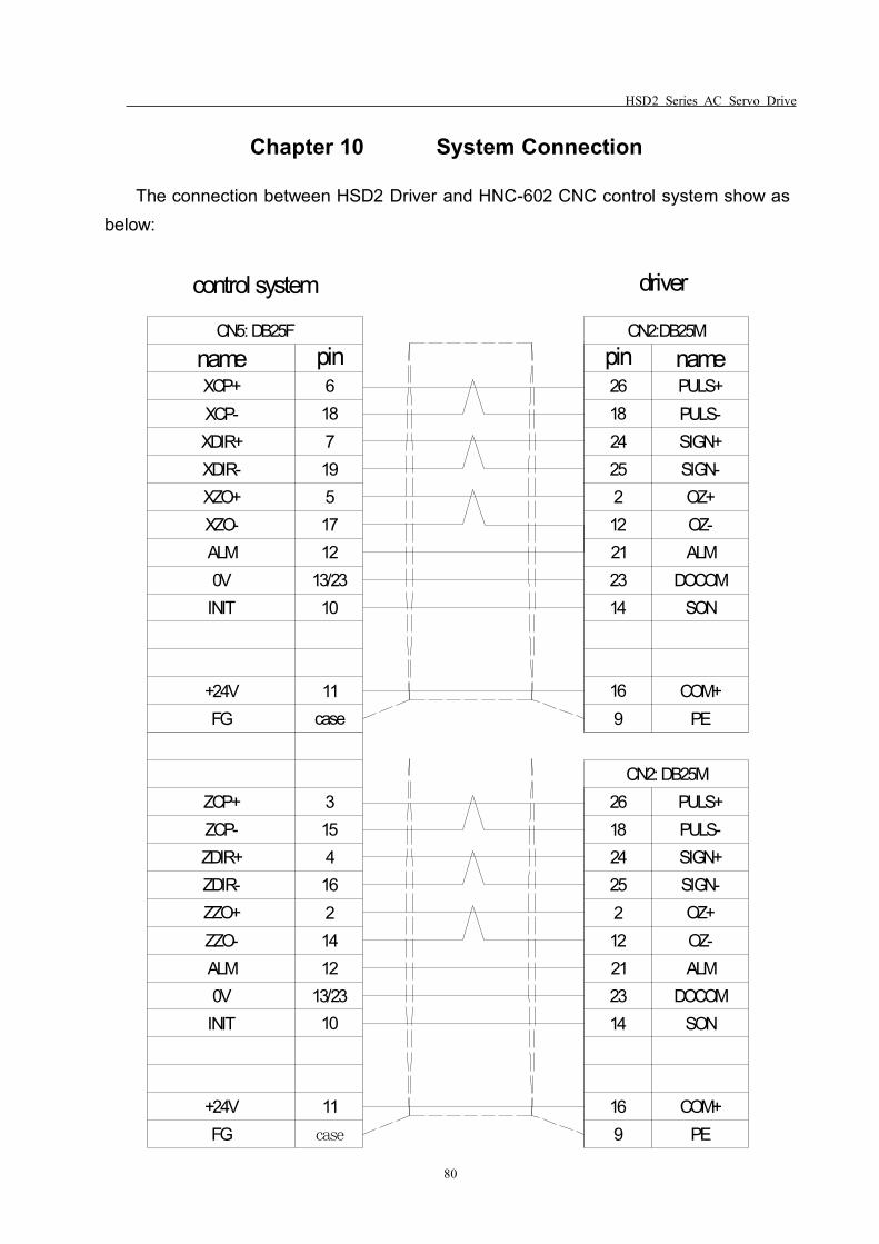
HSD2 Series AC Servo Drive
80
Chapter 10 System Connection
The connection between HSD2 Driver and HNC-602 CNC control system show asbelow:
nameCN5: DB25F
pinXCP+XCP-XDIR+XDIR-XZO+XZO-
0VALM
INIT
+24VFG
618719517
13/2312
10
11case
nameCN2:DB25M
pin26182425212212314
169
PULS+PULS-SIGN+SIGN-OZ+OZ-ALM
DOCOMSON
COM+PE
ZCP+ZCP-ZDIR+ZDIR-ZZO+ZZO-
0VALM
INIT
+24VFG
315416214
13/2312
10
11case
26182425212212314
169
PULS+PULS-SIGN+SIGN-OZ+OZ-ALM
DOCOMSON
COM+PE
CN2: DB25M
control system driver

HSD2 Series AC Servo Drive
Thanks for choosing HNC product.Any technique support, PLS feel free to contact our support teamTel: 86(20)84898493 Fax: 86(20)61082610URL: www.hncelectric.comEmail: [email protected]


![289 ' # '6& *#2 & 7and increased 11 -HSD2 mRNA expression) markers of syncytiotrophoblast differentiation. ... (PPAR ) which is regulated by VEGF-A expression [59, 60]. In addition,](https://img.pdfslide.us/doc/110x75/60f700cb21111f656f07cf7c/289-6-2-7-and-increased-11-hsd2-mrna-expression-markers-of-syncytiotrophoblast.jpg)