Embed Size (px)
Citation preview
HS-R
Installation and Operation Manual
MEG
4-Channel Low Speed Data Module with V.110 Rate Adaptation
APLEX-2100 MODULE

MEGAPLEX-2100 MODULE
HS-R 4-Channel Low Speed Data Module
with V.110 Rate Adaptation
Installation and Operation Manual
Notice This manual contains information that is proprietary to RAD Data Communications Ltd. ("RAD"). No part of this publication may be reproduced in any form whatsoever without prior written approval by RAD Data Communications.
Right, title and interest, all information, copyrights, patents, know-how, trade secrets and other intellectual property or other proprietary rights relating to this manual and to the HS-R and any software components contained therein are proprietary products of RAD protected under international copyright law and shall be and remain solely with RAD.
HS-R is a registered trademark of RAD. No right, license, or interest to such trademark is granted hereunder, and you agree that no such right, license, or interest shall be asserted by you with respect to such trademark.
You shall not copy, reverse compile or reverse assemble all or any portion of the Manual or the HS-R. You are prohibited from, and shall not, directly or indirectly, develop, market, distribute, license, or sell any product that supports substantially similar functionality as the HS-R, based on or derived in any way from the HS-R. Your undertaking in this paragraph shall survive the termination of this Agreement.
This Agreement is effective upon your opening of the HS-R package and shall continue until terminated. RAD may terminate this Agreement upon the breach by you of any term hereof. Upon such termination by RAD, you agree to return to RAD the HS-R and all copies and portions thereof.
For further information contact RAD at the address below or contact your local distributor.
International Headquarters RAD Data Communications Ltd. 24 Raoul Wallenberg St. Tel Aviv 69719 Israel Tel: 972-3-6458181 Fax: 972-3-6498250 E-mail: [email protected]
U.S. Headquarters RAD Data Communications Inc. 900 Corporate Drive Mahwah, NJ 07430 USA Tel: (201) 529-1100, Toll free: 1-800-444-7234 Fax: (201) 529-5777 E-mail: [email protected]
© 1988–2004 RAD Data Communications Ltd. Publication No. 764-214-02/04

1
Quick-Start Guide
If you are familiar with the product, use this guide to prepare it for operation.
Preliminary Preparations
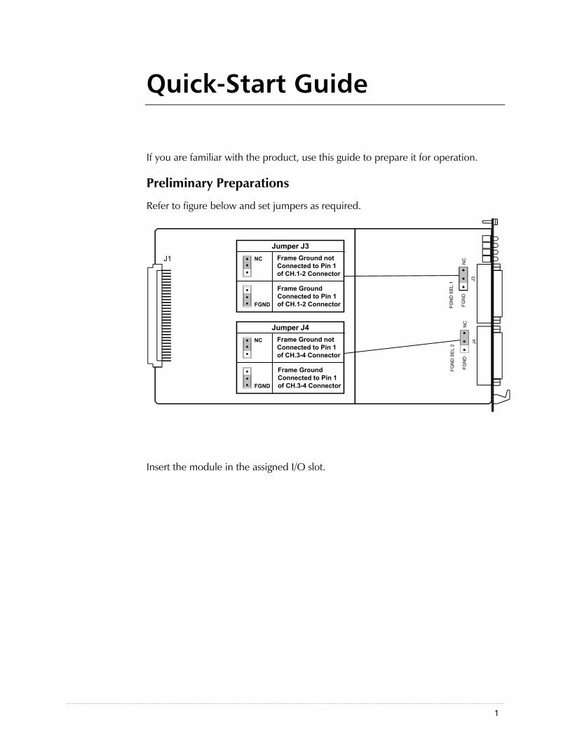
Refer to figure below and set jumpers as required.
Jumper J3NC Frame Ground not
Connected to Pin 1of CH.1-2 Connector
FGND
Frame GroundConnected to Pin 1of CH.1-2 Connector
Jumper J4NC Frame Ground not
Connected to Pin 1of CH.3-4 Connector
FGND
Frame GroundConnected to Pin 1of CH.3-4 Connector
J1
FGN
D
J3
FGN
D S
EL 1
NC
FGN
D
J4
FGN
D S
EL 2
NC
Insert the module in the assigned I/O slot.
Quick-Start Guide MP-2100 HS-R Installation and Operation Manual
2
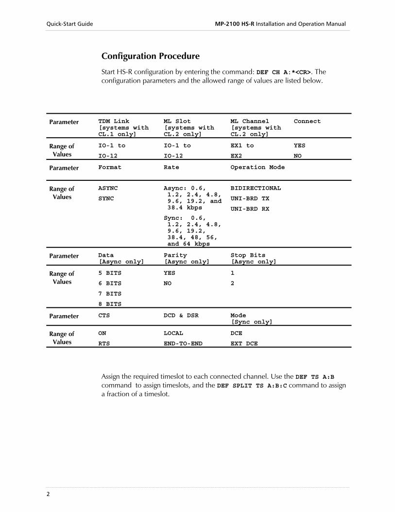
Configuration Procedure
Start HS-R configuration by entering the command: DEF CH A:*<CR>. The configuration parameters and the allowed range of values are listed below.
Parameter TDM Link [systems with CL.1 only]
ML Slot [systems with CL.2 only]
ML Channel [systems with CL.2 only]
Connect
Range of Values
IO-1 to
IO-12
IO-1 to
IO-12
EX1 to
EX2
YES
NO
Parameter
Format Rate Operation Mode
Range of Values
ASYNC
SYNC
Async: 0.6, 1.2, 2.4, 4.8, 9.6, 19.2, and 38.4 kbps
Sync: 0.6, 1.2, 2.4, 4.8, 9.6, 19.2, 38.4, 48, 56, and 64 kbps
BIDIRECTIONAL
UNI-BRD TX
UNI-BRD RX
Parameter Data [Async only]
Parity [Async only]
Stop Bits [Async only]
Range of Values
5 BITS
6 BITS
7 BITS
8 BITS
YES
NO
1
2
Parameter CTS DCD & DSR Mode [Sync only]
Range of Values
ON
RTS
LOCAL
END-TO-END
DCE
EXT DCE
Assign the required timeslot to each connected channel. Use the DEF TS A:B command to assign timeslots, and the DEF SPLIT TS A:B:C command to assign a fraction of a timeslot.
i
Contents
Chapter 1 Introduction 1.1 Overview....................................................................................................................1-1
Applications........................................................................................................................ 1-1 1.2 Physical Description....................................................................................................1-4 1.3 Functional Description................................................................................................1-5
Main Features..................................................................................................................... 1-5 Channel Characteristics....................................................................................................... 1-5 Timing................................................................................................................................ 1-6 Timeslot Assignment ........................................................................................................... 1-7 Configuration and Management.......................................................................................... 1-8 Diagnostics ......................................................................................................................... 1-8
1.4 Technical Specifications..............................................................................................1-9
Chapter 2 Module Installation and Operation 2.1 General ......................................................................................................................2-1 2.2 Preparation for Installation ..........................................................................................2-2
Module Installation ............................................................................................................. 2-2 2.3 Module Connections ..................................................................................................2-3
Interface Data..................................................................................................................... 2-3 Cable Connections.............................................................................................................. 2-4
2.4 Normal Indications .....................................................................................................2-4
Chapter 3 Configuration Instructions 3.1 Introduction................................................................................................................3-1 3.2 Configuration Procedure.............................................................................................3-1
Chapter 4 Tests & Diagnostics 4.1 General ......................................................................................................................4-1 4.2 Test and Diagnostic Functions.....................................................................................4-1
Local Digital Loopback (Local Loop).................................................................................... 4-1 Remote Digital Loopback (Remote Loop) ............................................................................ 4-1
4.3 Alarm Messages ..........................................................................................................4-3 4.4 Troubleshooting Instructions .......................................................................................4-4
Appendix A Operation with FCD-E1M and FCD-T1M A.1 Configuration Parameters........................................................................................... A-1 A.2 Alarm Messages ......................................................................................................... A-2
MP-2100 HS-R Installation and Operation Manual Table of Contents
ii
List of Figures
Figure 1-3 HS-R Module Panel ...................................................................................................1-4 Figure 2-1 HS-R Internal Settings .................................................................................................2-2 Figure 2-2 Channel Splitter Cable Wiring .....................................................................................2-4 Figure 4-1 Local Digital Loopback, Signal Path.............................................................................4-2 Figure 4-2 Remote Digital Loopback, Signal Path .........................................................................4-2
List of Tables
Table 1-1 Utilization of Main Link Timeslots ................................................................................1-7 Table 2-1 CH. 1-2 Connector, Pin Assignment.............................................................................2-3 Table 3-1 Module HS-R Channel Parameters ...............................................................................3-1 Table 4-1 HS-R Alarm Messages ..................................................................................................4-3 Table A-1. FCD Channel Parameters........................................................................................... A-1 Table A-2. FCD Alarm Messages ................................................................................................. A-2
Overview 1-1
Chapter 1 Introduction
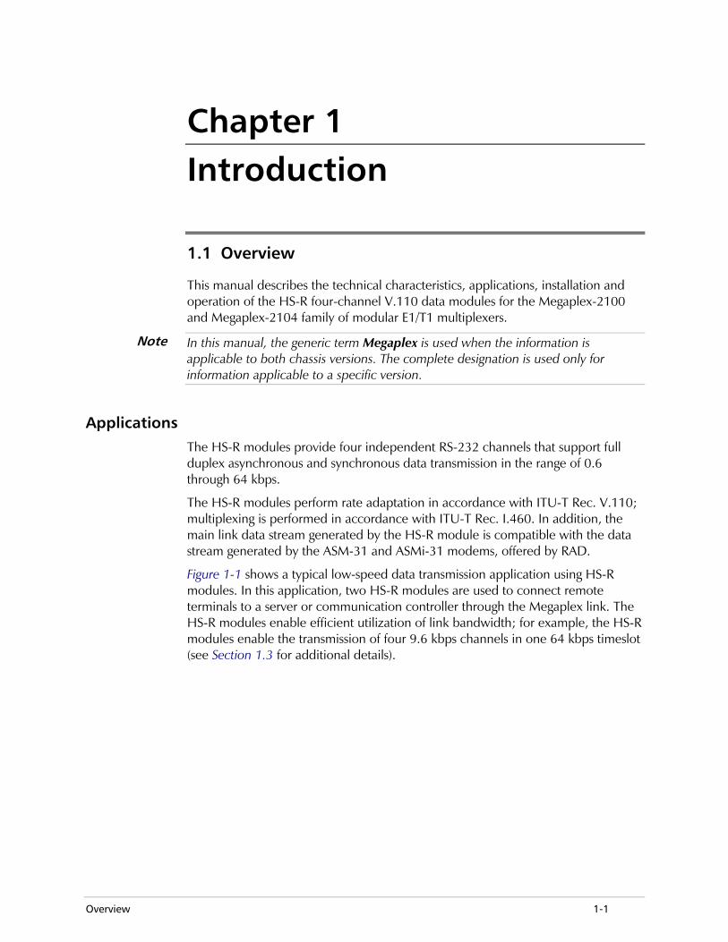
1.1 Overview
This manual describes the technical characteristics, applications, installation and operation of the HS-R four-channel V.110 data modules for the Megaplex-2100 and Megaplex-2104 family of modular E1/T1 multiplexers.
In this manual, the generic term Megaplex is used when the information is applicable to both chassis versions. The complete designation is used only for information applicable to a specific version.
Applications The HS-R modules provide four independent RS-232 channels that support full duplex asynchronous and synchronous data transmission in the range of 0.6 through 64 kbps.
The HS-R modules perform rate adaptation in accordance with ITU-T Rec. V.110; multiplexing is performed in accordance with ITU-T Rec. I.460. In addition, the main link data stream generated by the HS-R module is compatible with the data stream generated by the ASM-31 and ASMi-31 modems, offered by RAD.
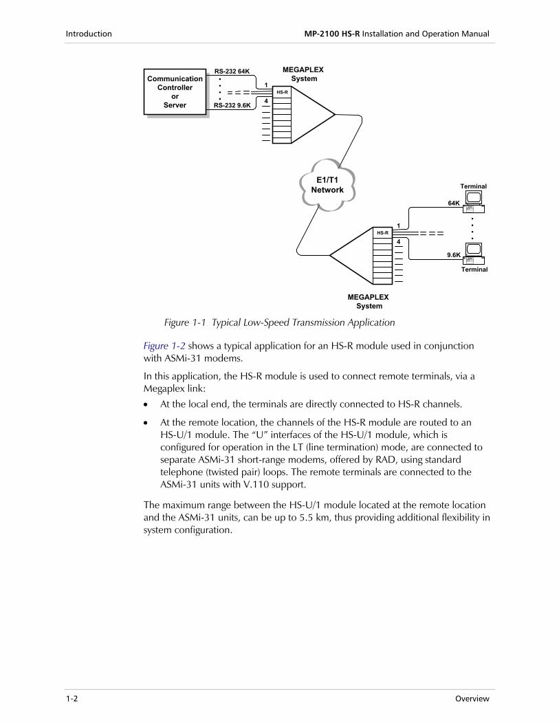
Figure 1-1 shows a typical low-speed data transmission application using HS-R modules. In this application, two HS-R modules are used to connect remote terminals to a server or communication controller through the Megaplex link. The HS-R modules enable efficient utilization of link bandwidth; for example, the HS-R modules enable the transmission of four 9.6 kbps channels in one 64 kbps timeslot (see Section 1.3 for additional details).
Note
Introduction MP-2100 HS-R Installation and Operation Manual
1-2 Overview
MEGAPLEX System
CommunicationController
orServer
HS-R
RS-232 64K
1
4RS-232 9.6K
MEGAPLEX System
E1/T1Network
HS-R1
4
64K
Terminal
9.6K
Terminal
....
....
Figure 1-1 Typical Low-Speed Transmission Application
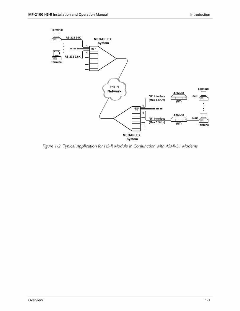
Figure 1-2 shows a typical application for an HS-R module used in conjunction with ASMi-31 modems.
In this application, the HS-R module is used to connect remote terminals, via a Megaplex link:
• At the local end, the terminals are directly connected to HS-R channels.
• At the remote location, the channels of the HS-R module are routed to an HS-U/1 module. The “U” interfaces of the HS-U/1 module, which is configured for operation in the LT (line termination) mode, are connected to separate ASMi-31 short-range modems, offered by RAD, using standard telephone (twisted pair) loops. The remote terminals are connected to the ASMi-31 units with V.110 support.
The maximum range between the HS-U/1 module located at the remote location and the ASMi-31 units, can be up to 5.5 km, thus providing additional flexibility in system configuration.
MP-2100 HS-R Installation and Operation Manual Introduction
Overview 1-3
HS-R
RS-232 64K
1
4
....RS-232 9.6K
MEGAPLEX System
E1/T1Network
HS-U/1(LT)
1
4
ASMi-31
(NT)
64K
MEGAPLEX System
"U" Interface(Max 5.5Km)
Terminal
ASMi-31
(NT)
9.6K
Terminal
"U" Interface(Max 5.5Km)
Terminal
Terminal
....
Figure 1-2 Typical Application for HS-R Module in Conjunction with ASMi-31 Modems
Introduction MP-2100 HS-R Installation and Operation Manual
1-4 Physical Description
1.2 Physical Description
The HS-R modules occupy one I/O module slot in the Megaplex chassis.
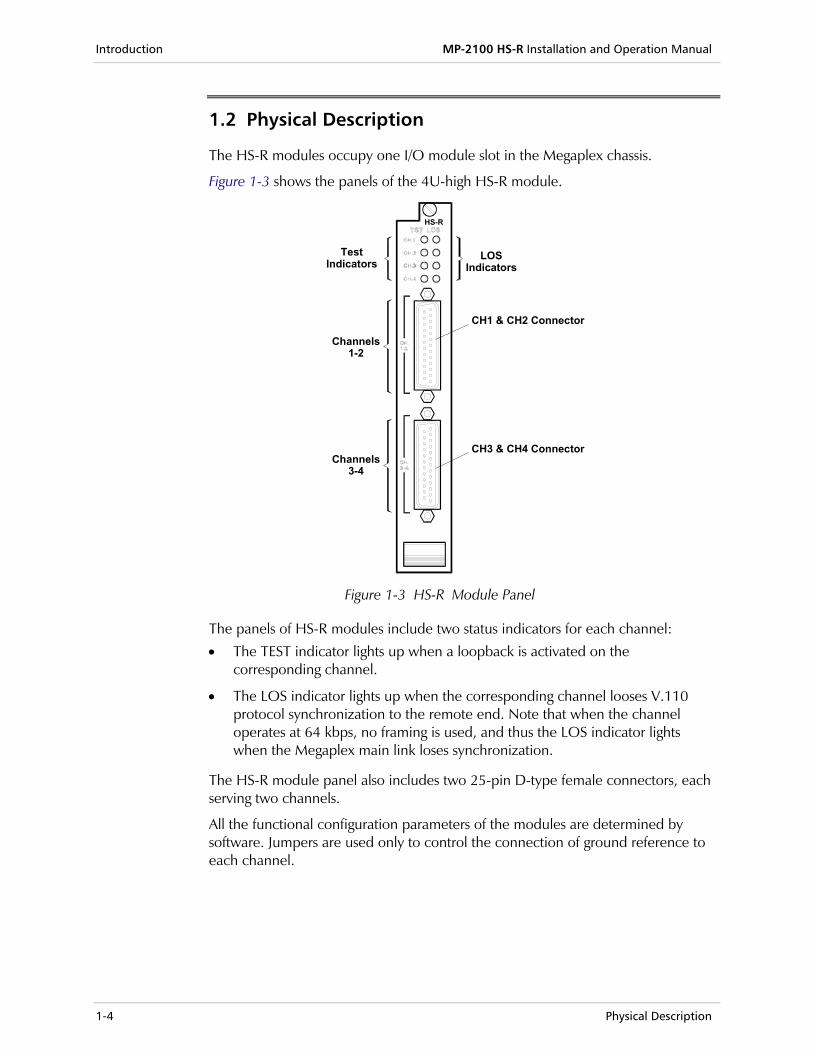
Figure 1-3 shows the panels of the 4U-high HS-R module.
TestIndicators
HS-R
Channels1-2
Channels3-4
LOSIndicators
CH1 & CH2 Connector
CH3 & CH4 Connector
Figure 1-3 HS-R Module Panel
The panels of HS-R modules include two status indicators for each channel:
• The TEST indicator lights up when a loopback is activated on the corresponding channel.
• The LOS indicator lights up when the corresponding channel looses V.110 protocol synchronization to the remote end. Note that when the channel operates at 64 kbps, no framing is used, and thus the LOS indicator lights when the Megaplex main link loses synchronization.
The HS-R module panel also includes two 25-pin D-type female connectors, each serving two channels.
All the functional configuration parameters of the modules are determined by software. Jumpers are used only to control the connection of ground reference to each channel.
MP-2100 HS-R Installation and Operation Manual Introduction
Functional Description 1-5
1.3 Functional Description
Main Features Each HS-R channel operates independently. All the channel operating parameters are controlled by Megaplex system management.
Basically, each HS-R channel is assigned an individual timeslot in the T1 or E1 main link frame. The HS-R modules also support split timeslot assignment, therefore improving main link bandwidth utilization.
The timeslots assigned to HS-R channels can be manually assigned by the user. User-controlled manual timeslot assignment allows the routing of the bit stream generated by each local channel to any other compatible Megaplex channel at the remote site, e.g., to another channel of a high-speed module such as HS-2, HS-3, HS-Q, HS-R, HS-S, HS-4, or HS-U, or to another type of module, such as an HS-ETH module.
Channel Characteristics Each HS-R module channel can be configured by the user for asynchronous or synchronous operation. Each channel has a DCE RS-232 interface.
Asynchronous Mode
The data rates supported in the asynchronous mode are 0.6, 1.2, 2.4, 4.8, 9.6, 19.2, and 38.4 kbps. The V.110 frame structure used at these rates consists of 80 bits.
In the asynchronous mode, the user can specify the structure of the word format to be processed by each channel (this structure must be identical to that used by the user's DTE). The available options are as follows:
• Number of data bits: 5, 6, 7, or 8.
• Use of parity: if the user's DTE word format includes a parity bit, the user can enable transparent end-to-end transfer of the original parity bit. The module itself does not check the parity of the incoming data.
• Number of stop bits: 1 or 2.
In addition to the selected parameters, the word format includes one start bit.
Synchronous Mode
The data rates supported in the synchronous mode are 0.6, 1.2, 2.4, 4.8, 9.6, 19.2, 38.4, 48, 56, and 64 kbps. The V.110 frame structure used in the synchronous mode depends on the data rate:
• At rates up to 38.4 kbps, the V.110 frame consists of 80 bits.
• At 48 kbps, the V.110 frame consists of 32 bits.
Introduction MP-2100 HS-R Installation and Operation Manual
1-6 Functional Description
• At 56 kbps, an 8-bit frame is used. This frame uses seven frame bits for transparent transfer of the user's 56 kbps data stream, and the eighth bit is always “1”.
• At 64 kbps, no framing is used (transparent transfer of user's data stream).
Interface Control Lines
The RS-232 interface control signals are locally supported in accordance with the RS-232 protocol, with the following modifications:
• The DSR line is continuously active (ON), except when the end-to-end transmission of control signals is enabled.
• The DCD line is ON when the local Megaplex unit is synchronized, and is OFF when the unit loses synchronization.
• For flexibility in application, the user can program the state of the CTS line. The available selections are:
The CTS line is continuously active (ON).
The state of the local CTS line tracks the state of the local RTS line.
• The user can enable end-to-end transmission of the states of the local DTR and RTS lines to the remote DSR and DCD lines, respectively.
Note that control signals are not supported at the 56 or 64 kbps channel rates.
Channel Connectors
The data channels of the HS-R module are terminated in two 25-pin D-type female connectors: one carries Channels 1 and 2, and the other carries Channels 3 and 4.
As an option, RAD offers two types of channel splitter cables, which enable direct connection of data equipment with RS-232 interfaces to an HS-R 25-pin connector:
• CBL-HSR/F, which terminates into two 25-pin D-type female connectors.
• CBL-HSR/M, which terminates into two 25-pin D-type male connectors.
Timing When operating in the synchronous mode, the timing of the HS-R channel interfaces is locked to the Megaplex nodal timing.
The timing mode of each HS-R module channel can be selected by the user. Two options are available:
• DCE: the interface provides transmit and receive clock signals to the user's data equipment (DTE). The user's DTE must receive and transmit at the rate of the clock signals provided by the HS-R channel interface.
MP-2100 HS-R Installation and Operation Manual Introduction
Functional Description 1-7
• EXT DCE (DTE1): the interface provides a receive clock signal to the user's DTE, and accepts the transmit clock from the user's DTE. The user's DTE must operate with loopback timing; that is, it must transmit at the rate of the receive clock signal provided by the HS-R channel interface. This timing mode is suitable for tail-end applications.
Timeslot Assignment The HS-R module processes the payload data from all the channels in accordance with the guidelines of ITU-T Rec. I.460. It then organizes the payload data for transmission in the main link timeslots of the Megaplex, to achieve optimal packing of data.
Data in the main link timeslots is formatted in 8-bit groups (octets). In accordance with ITU-T Rec. I.460, channels carrying data rates lower than the B-channel rate can be assigned 2, 4, or 8 bits in each octet. When necessary, rate adaptation is performed to convert the data rate at which the users' DTE actually operates to the rate corresponding to the number of bits that can be assigned in a main link timeslot octet.
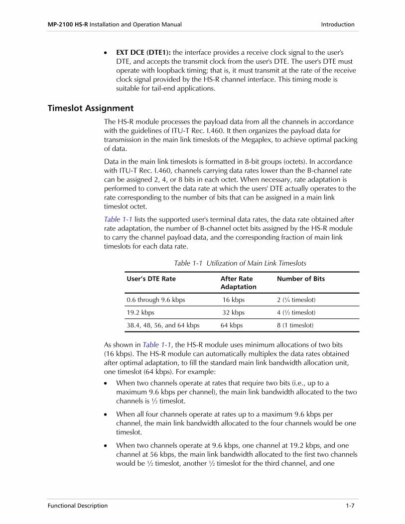
Table 1-1 lists the supported user's terminal data rates, the data rate obtained after rate adaptation, the number of B-channel octet bits assigned by the HS-R module to carry the channel payload data, and the corresponding fraction of main link timeslots for each data rate.
Table 1-1 Utilization of Main Link Timeslots
User’s DTE Rate After Rate Adaptation
Number of Bits
0.6 through 9.6 kbps 16 kbps 2 (¼ timeslot)
19.2 kbps 32 kbps 4 (½ timeslot)
38.4, 48, 56, and 64 kbps 64 kbps 8 (1 timeslot)
As shown in Table 1-1, the HS-R module uses minimum allocations of two bits (16 kbps). The HS-R module can automatically multiplex the data rates obtained after optimal adaptation, to fill the standard main link bandwidth allocation unit, one timeslot (64 kbps). For example:
• When two channels operate at rates that require two bits (i.e., up to a maximum 9.6 kbps per channel), the main link bandwidth allocated to the two channels is ½ timeslot.
• When all four channels operate at rates up to a maximum 9.6 kbps per channel, the main link bandwidth allocated to the four channels would be one timeslot.
• When two channels operate at 9.6 kbps, one channel at 19.2 kbps, and one channel at 56 kbps, the main link bandwidth allocated to the first two channels would be ½ timeslot, another ½ timeslot for the third channel, and one
Introduction MP-2100 HS-R Installation and Operation Manual
1-8 Functional Description
additional slot would be used for the fourth channel. Thus, two full timeslots would be required.
The maximum number of main link timeslots that may be required by an HS-R module is four.
The user can enable split timeslot allocation. In this case, each channel which does not require a full timeslot can be allocated the required number of bits (in accordance with Table 1-1 in a user-selected timeslot.
Configuration and Management All the module operating parameters are controlled by means of the Megaplex system management., which support flexible timeslot routing. The user selects the timeslots assigned to HS-R channels in the T1 or E1 main link frame, in order to route the bit stream generated by the multiplexing process described above in each local channel.
Each main link allocation unit generated by an HS-R module can be independently routed to any other compatible module installed in the remote Megaplex unit, configured for the same combination of data rates. Moreover, the HS-R modules support split timeslot allocation.
Diagnostics The HS-R modules support self-diagnostics upon power-up, as well as powerful testing capabilities controlled by means of the system management functions, thereby reducing downtime to a minimum.
The test and loopback functions, that can be individually activated by the system management functions for each module channel, include:
• Local digital loopback.
• Remote digital loopback.
MP-2100 HS-R Installation and Operation Manual Introduction
Technical Specifications 1-9
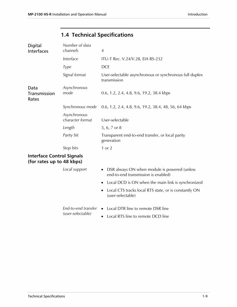
1.4 Technical Specifications
Digital Interfaces
Number of data channels
4
Interface ITU-T Rec. V.24/V.28, EIA RS-232
Type DCE
Signal format User-selectable asynchronous or synchronous full duplex transmission
Data Transmission Rates
Asynchronous mode
0.6, 1.2, 2.4, 4.8, 9.6, 19.2, 38.4 kbps
Synchronous mode 0.6, 1.2, 2.4, 4.8, 9.6, 19.2, 38.4, 48, 56, 64 kbps
Asynchronous character format
Length
Parity bit
Stop bits
User-selectable
5, 6, 7 or 8
Transparent end-to-end transfer, or local parity generation
1 or 2
Interface Control Signals (for rates up to 48 kbps)
Local support • DSR always ON when module is powered (unless end-to-end transmission is enabled)
• Local DCD is ON when the main link is synchronized
• Local CTS tracks local RTS state, or is constantly ON (user-selectable)
End-to-end transfer (user-selectable)
• Local DTR line to remote DSR line
• Local RTS line to remote DCD line
Introduction MP-2100 HS-R Installation and Operation Manual
1-10 Technical Specifications
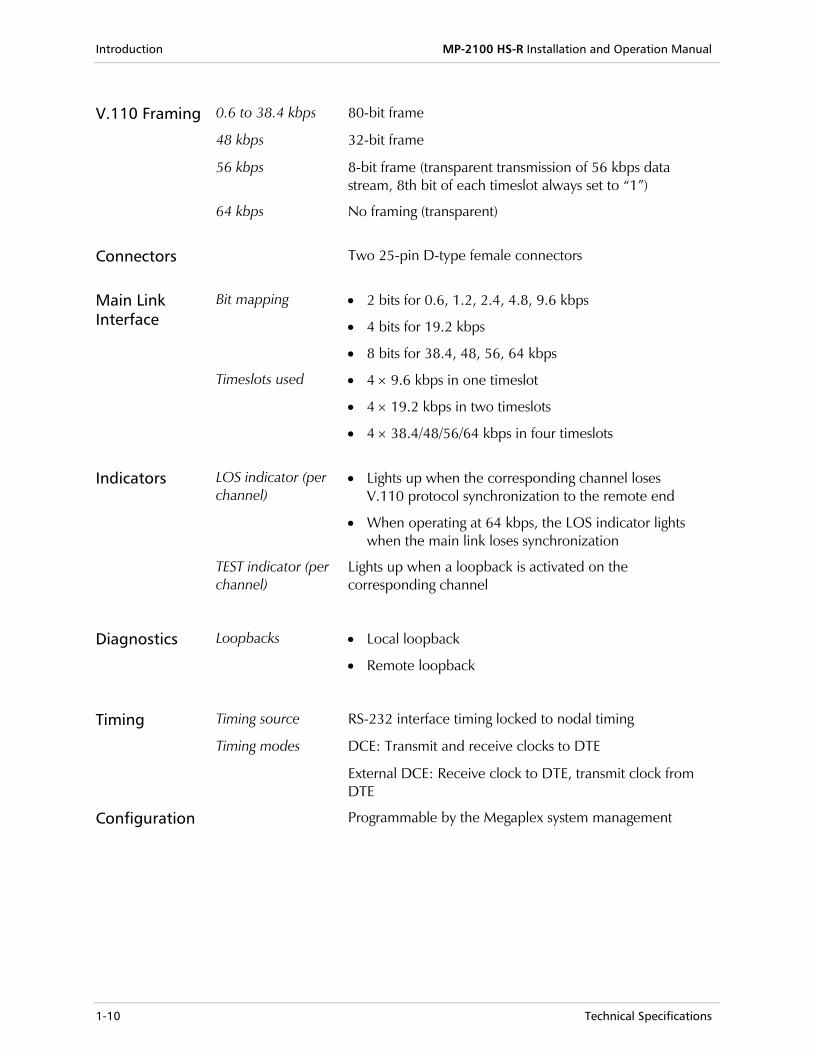
V.110 Framing 0.6 to 38.4 kbps 80-bit frame
48 kbps 32-bit frame
56 kbps 8-bit frame (transparent transmission of 56 kbps data stream, 8th bit of each timeslot always set to “1”)
64 kbps No framing (transparent)
Connectors Two 25-pin D-type female connectors
Main Link Interface
Bit mapping • 2 bits for 0.6, 1.2, 2.4, 4.8, 9.6 kbps
• 4 bits for 19.2 kbps
• 8 bits for 38.4, 48, 56, 64 kbps
Timeslots used • 4 × 9.6 kbps in one timeslot
• 4 × 19.2 kbps in two timeslots
• 4 × 38.4/48/56/64 kbps in four timeslots
Indicators LOS indicator (per channel)
• Lights up when the corresponding channel loses V.110 protocol synchronization to the remote end
• When operating at 64 kbps, the LOS indicator lights when the main link loses synchronization
TEST indicator (per channel)
Lights up when a loopback is activated on the corresponding channel
Diagnostics Loopbacks • Local loopback
• Remote loopback
Timing Timing source RS-232 interface timing locked to nodal timing
Timing modes DCE: Transmit and receive clocks to DTE
External DCE: Receive clock to DTE, transmit clock from DTE
Configuration Programmable by the Megaplex system management
Preparation for Installation 2-1
Chapter 2 Module Installation and Operation
2.1 General
This chapter provides installation and operation instructions for the HS-R modules. The information presented in this chapter supplements the general installation and operation information appearing in the Megaplex-2100 System Installation and Operation Manual.
Before performing any internal settings, adjustment, maintenance, or repairs, first disconnect all the cables from the module, and then remove the module from the Megaplex enclosure. No internal settings, adjustment, maintenance, and repairs may be performed by either the operator or the user; such activities may be performed only by a skilled technician who is aware of the hazards involved. Always observe standard safety precautions during installation, operation, and maintenance of this product.
The HS-R module contains components sensitive to electrostatic discharge (ESD). To prevent ESD damage, always hold the module by its sides, and do not touch the module components or connectors.
Warning
Caution
Module Installation and Operation MP-2100 HS-R Installation and Operation Manual
2-2 Preparation for Installation
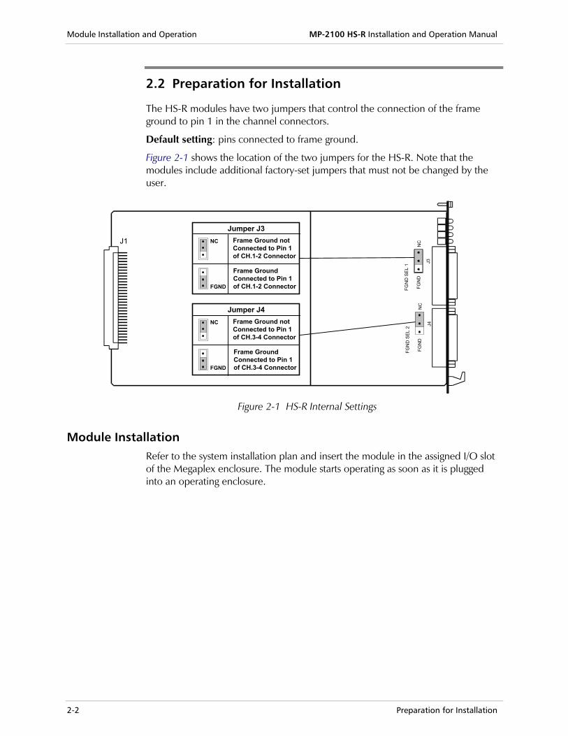
2.2 Preparation for Installation
The HS-R modules have two jumpers that control the connection of the frame ground to pin 1 in the channel connectors.
Default setting: pins connected to frame ground.
Figure 2-1 shows the location of the two jumpers for the HS-R. Note that the modules include additional factory-set jumpers that must not be changed by the user.
Jumper J3NC Frame Ground not
Connected to Pin 1of CH.1-2 Connector
FGND
Frame GroundConnected to Pin 1of CH.1-2 Connector
Jumper J4NC Frame Ground not
Connected to Pin 1of CH.3-4 Connector
FGND
Frame GroundConnected to Pin 1of CH.3-4 Connector
J1
FGN
D
J3
FGN
D S
EL 1
NC
FGN
D
J4
FGN
D S
EL 2
NC
Figure 2-1 HS-R Internal Settings
Module Installation Refer to the system installation plan and insert the module in the assigned I/O slot of the Megaplex enclosure. The module starts operating as soon as it is plugged into an operating enclosure.
MP-2100 HS-R Installation and Operation Manual Module Installation and Operation
Module Connections 2-3
2.3 Module Connections
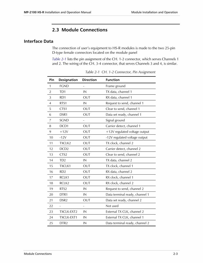
Interface Data The connection of user’s equipment to HS-R modules is made to the two 25-pin D-type female connectors located on the module panel
Table 2-1 lists the pin assignment of the CH. 1-2 connector, which serves Channels 1 and 2. The wiring of the CH. 3-4 connector, that serves Channels 3 and 4, is similar.
Table 2-1 CH. 1-2 Connector, Pin Assignment
Pin Designation Direction Function
1 FGND - Frame ground
2 TD1 IN TX data, channel 1
3 RD1 OUT RX data, channel 1
4 RTS1 IN Request to send, channel 1
5 CTS1 OUT Clear to send, channel 1
6 DSR1 OUT Data set ready, channel 1
7 SGND - Signal ground
8 DCD1 OUT Carrier detect, channel 1
9 +12V OUT +12V regulated voltage output
10 -12V OUT -12V regulated voltage output
11 TXCLK2 OUT TX clock, channel 2
12 DCD2 OUT Carrier detect, channel 2
13 CTS2 OUT Clear to send, channel 2
14 TD2 IN TX data, channel 2
15 TXCLK1 OUT TX clock, channel 1
16 RD2 OUT RX data, channel 2
17 RCLK1 OUT RX clock, channel 1
18 RCLK2 OUT RX clock, channel 2
19 RTS2 IN Request to send, channel 2
20 DTR1 IN Data terminal ready, channel 1
21 DSR2 OUT Data set ready, channel 2
22 - - Not used
23 TXCLK-EXT2 IN External TX CLK, channel 2
24 TXCLK-EXT1 IN External TX CLK, channel 1
25 DTR2 IN Data terminal ready, channel 2
Module Installation and Operation MP-2100 HS-R Installation and Operation Manual
2-4 Normal Indications
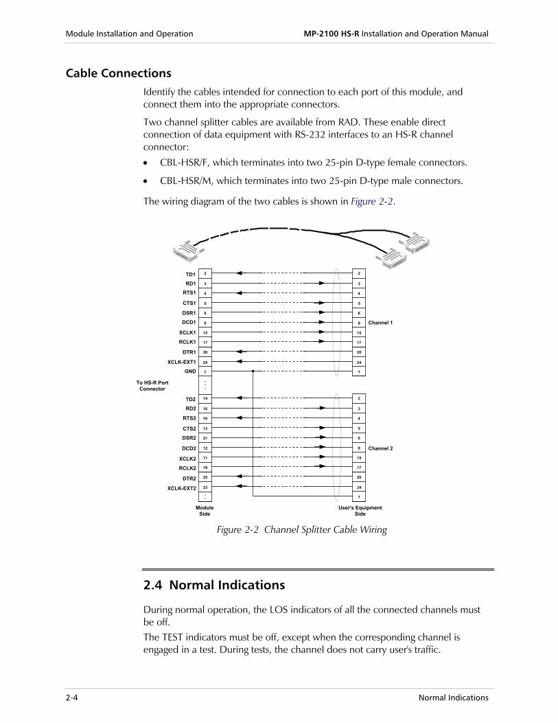
Cable Connections Identify the cables intended for connection to each port of this module, and connect them into the appropriate connectors.
Two channel splitter cables are available from RAD. These enable direct connection of data equipment with RS-232 interfaces to an HS-R channel connector:
• CBL-HSR/F, which terminates into two 25-pin D-type female connectors.
• CBL-HSR/M, which terminates into two 25-pin D-type male connectors.
The wiring diagram of the two cables is shown in Figure 2-2.
2
3
4
5
6
8
15
17
20
24
7
2
3
4
5
6
8
15
17
20
24
7
2
3
4
5
6
8
15
17
20
24
7
14
16
19
13
21
12
11
18
25
23
TD1
RTS1
CTS1
DSR1DCD1
XCLK1
RCLK1
DTR1
XCLK-EXT1
GND
RD1
Channel 1
Channel 2
To HS-R PortConnector
TD2
RTS2
CTS2
DSR2
DCD2
XCLK2
RCLK2
DTR2
XCLK-EXT2
RD2
ModuleSide
User's EquipmentSide
...
..
Figure 2-2 Channel Splitter Cable Wiring
2.4 Normal Indications
During normal operation, the LOS indicators of all the connected channels must be off. The TEST indicators must be off, except when the corresponding channel is engaged in a test. During tests, the channel does not carry user's traffic.
Configuration Procedure 3-1
Chapter 3 Configuration Instructions
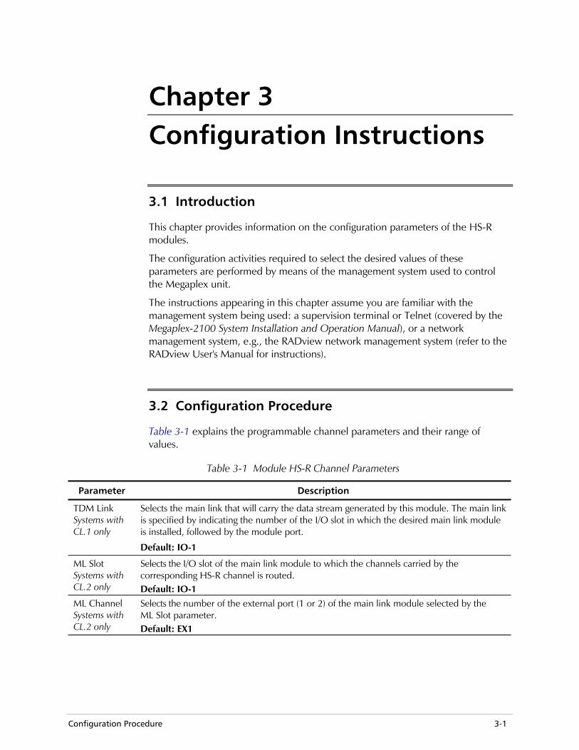
3.1 Introduction
This chapter provides information on the configuration parameters of the HS-R modules.
The configuration activities required to select the desired values of these parameters are performed by means of the management system used to control the Megaplex unit.
The instructions appearing in this chapter assume you are familiar with the management system being used: a supervision terminal or Telnet (covered by the Megaplex-2100 System Installation and Operation Manual), or a network management system, e.g., the RADview network management system (refer to the RADview User's Manual for instructions).
3.2 Configuration Procedure
Table 3-1 explains the programmable channel parameters and their range of values.
Table 3-1 Module HS-R Channel Parameters
Parameter Description
TDM Link Systems with CL.1 only
Selects the main link that will carry the data stream generated by this module. The main link is specified by indicating the number of the I/O slot in which the desired main link module is installed, followed by the module port.
Default: IO-1
ML Slot Systems with CL.2 only
Selects the I/O slot of the main link module to which the channels carried by the corresponding HS-R channel is routed. Default: IO-1
ML Channel Systems with CL.2 only
Selects the number of the external port (1 or 2) of the main link module selected by the ML Slot parameter. Default: EX1
Configuration Instructions MP-2100 HS-R Installation and Operation Manual
3-2 Configuration Procedure
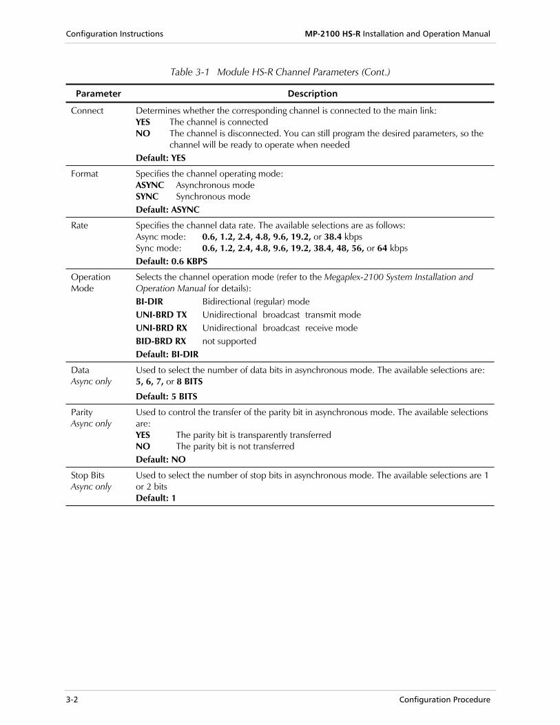
Table 3-1 Module HS-R Channel Parameters (Cont.)
Parameter Description
Connect Determines whether the corresponding channel is connected to the main link: YES The channel is connected NO The channel is disconnected. You can still program the desired parameters, so the
channel will be ready to operate when needed Default: YES
Format Specifies the channel operating mode: ASYNC Asynchronous mode SYNC Synchronous mode Default: ASYNC
Rate Specifies the channel data rate. The available selections are as follows: Async mode: 0.6, 1.2, 2.4, 4.8, 9.6, 19.2, or 38.4 kbps Sync mode: 0.6, 1.2, 2.4, 4.8, 9.6, 19.2, 38.4, 48, 56, or 64 kbps Default: 0.6 KBPS
Operation Mode
Selects the channel operation mode (refer to the Megaplex-2100 System Installation and Operation Manual for details): BI-DIR Bidirectional (regular) mode UNI-BRD TX Unidirectional broadcast transmit mode UNI-BRD RX Unidirectional broadcast receive mode BID-BRD RX not supported Default: BI-DIR
Data Async only
Used to select the number of data bits in asynchronous mode. The available selections are: 5, 6, 7, or 8 BITS
Default: 5 BITS
Parity Async only
Used to control the transfer of the parity bit in asynchronous mode. The available selections are: YES The parity bit is transparently transferred NO The parity bit is not transferred Default: NO
Stop Bits Async only
Used to select the number of stop bits in asynchronous mode. The available selections are 1 or 2 bits Default: 1
MP-2100 HS-R Installation & Operation Manual Configuration Instructions
Configuration Procedure 3-3
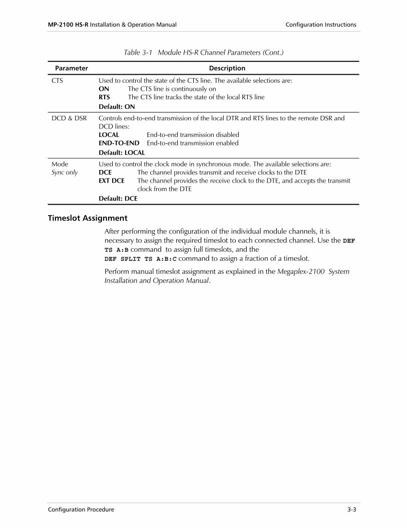
Table 3-1 Module HS-R Channel Parameters (Cont.)
Parameter Description
CTS Used to control the state of the CTS line. The available selections are: ON The CTS line is continuously on RTS The CTS line tracks the state of the local RTS line Default: ON
DCD & DSR Controls end-to-end transmission of the local DTR and RTS lines to the remote DSR and DCD lines: LOCAL End-to-end transmission disabled END-TO-END End-to-end transmission enabled Default: LOCAL
Mode Sync only
Used to control the clock mode in synchronous mode. The available selections are: DCE The channel provides transmit and receive clocks to the DTE EXT DCE The channel provides the receive clock to the DTE, and accepts the transmit
clock from the DTE Default: DCE
Timeslot Assignment
After performing the configuration of the individual module channels, it is necessary to assign the required timeslot to each connected channel. Use the DEF TS A:B command to assign full timeslots, and the DEF SPLIT TS A:B:C command to assign a fraction of a timeslot.
Perform manual timeslot assignment as explained in the Megaplex-2100 System Installation and Operation Manual.

Configuration Instructions MP-2100 HS-R Installation and Operation Manual
3-4 Configuration Procedure
Test and Diagnostic Functions 4-1
Chapter 4 Tests & Diagnostics
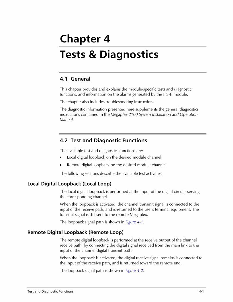
4.1 General
This chapter provides and explains the module-specific tests and diagnostic functions, and information on the alarms generated by the HS-R module.
The chapter also includes troubleshooting instructions.
The diagnostic information presented here supplements the general diagnostics instructions contained in the Megaplex-2100 System Installation and Operation Manual.
4.2 Test and Diagnostic Functions
The available test and diagnostics functions are:
• Local digital loopback on the desired module channel.
• Remote digital loopback on the desired module channel.
The following sections describe the available test activities.
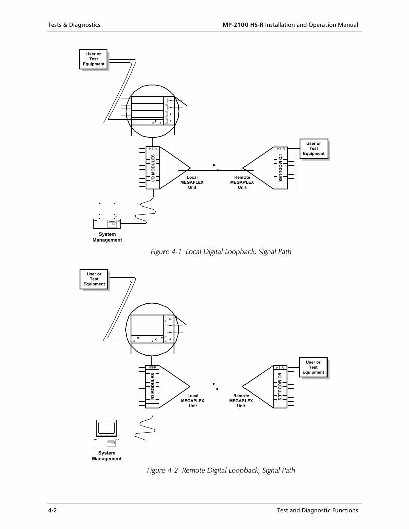
Local Digital Loopback (Local Loop) The local digital loopback is performed at the input of the digital circuits serving the corresponding channel.
When the loopback is activated, the channel transmit signal is connected to the input of the receive path, and is returned to the user's terminal equipment. The transmit signal is still sent to the remote Megaplex.
The loopback signal path is shown in Figure 4-1.
Remote Digital Loopback (Remote Loop) The remote digital loopback is performed at the receive output of the channel receive path, by connecting the digital signal received from the main link to the input of the channel digital transmit path.
When the loopback is activated, the digital receive signal remains is connected to the input of the receive path, and is returned toward the remote end.
The loopback signal path is shown in Figure 4-2.
Tests & Diagnostics MP-2100 HS-R Installation and Operation Manual
4-2 Test and Diagnostic Functions
I/O M
OD
ULE
SHS-R
I/O M
OD
ULES
SystemManagement
User orTest
Equipment
.
.
.
.
.
.
.
.
User orTest
Equipment
HS-R
LocalMEGAPLEX
Unit
RemoteMEGAPLEX
Unit
Figure 4-1 Local Digital Loopback, Signal Path
SystemManagement
.
.
.
.
.
.
.
.
User orTest
Equipment
LocalMEGAPLEX
Unit
RemoteMEGAPLEX
Unit
HS-R
I/O M
OD
ULES
User orTest
Equipment
I/O M
OD
ULE
S
HS-R
Figure 4-2 Remote Digital Loopback, Signal Path
MP-2100 HS-R Installation and Operation Manual Tests & Diagnostics
Alarm Messages 4-3
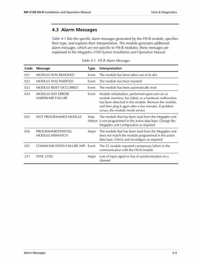
4.3 Alarm Messages
Table 4-1 lists the specific alarm messages generated by the HS-R module, specifies their type, and explains their interpretation. The module generates additional alarm messages, which are not specific to HS-R modules; these messages are explained in the Megaplex-2100 System Installation and Operation Manual.
Table 4-1 HS-R Alarm Messages
Code Message Type Interpretation
021 MODULE WAS REMOVED Event The module has been taken out of its slot
022 MODULE WAS INSERTED Event The module has been inserted
023 MODULE RESET OCCURRED Event The module has been automatically reset
024 MODULE INIT ERROR/ HARDWARE FAILURE
Event Module initialization, performed upon turn-on or module insertion, has failed, or a hardware malfunction has been detected in this module. Remove the module, and then plug it again after a few minutes. If problem recurs, the module needs service
025 NOT PROGRAMMED MODULE State (Minor)
The module that has been read from the Megaplex unit is not programmed in the active data base. Change the Megaplex unit configuration as required
026 PROGRAMMED/INSTALL MODULE MISMATCH
Major The module that has been read from the Megaplex unit does not match the module programmed in the active data base. Check and reconfigure as required
031 COMMUNICATION FAILURE (MP) Event The CL module reported a temporary failure in the communication with the HS-R module
211 SYNC LOSS Major Loss of input signal or loss of synchronization on a channel
Tests & Diagnostics MP-2100 HS-R Installation and Operation Manual
4-4 Troubleshooting Instructions
4.4 Troubleshooting Instructions
The loops available on the HS-R module provide a rapid and efficient way to identify the general location of a fault either of the HS-R modules connected in a link, in the external equipment, or in the connections to the channels.
If the LOS indicator of an HS-R channel lights, or a complaint is received regarding the transmission of data through one of the HS-R channels, perform the following procedure until the problem is located. After each step, continue to the next step only if the previously specified test has been successfully completed.
If the problem is detected when a connection between two new users is activated for the first time, before starting the troubleshooting procedure described below thoroughly check the timeslot allocation, the configuration of the two Megaplex units that provide the new connection, and the configuration of the user's terminal equipment.
• Request the user to perform a local loopback test on the local data equipment. If the user equipment does not receive its own signal, the problem is in the user equipment. After correcting the problem, continue troubleshooting as explained below.
• If the signal is not received when the remote digital loopback is activated, activate the local main link loop on the local Megaplex unit:
If the user equipment does not receive its own signal when the main link loop is connected, the problem is in the local unit.
If the signal is received when the main link local loopback is activated, activate the remote main link loop. If the user equipment does not receive its own signal, the problem is either in the timeslot allocation, or in the remote unit.
Note
Configuration Parameters A-1
Appendix A Operation with FCD-E1M and FCD-T1M Operation of the HS-R module with FCD-E1M and FCD-T1M is generally similar to its operation with the Megaplex-2100/2104 family of modular E1/T1 multiplexers, as previously explained in this manual. The differences are seen in the following two areas:
• Configuration parameters
• Alarm messages
This appendix identifies and lists these differences only. For a full description of the configuration parameters and alarm messages, refer to the Configuration Instructions and Alarm Messages sections in this manual.
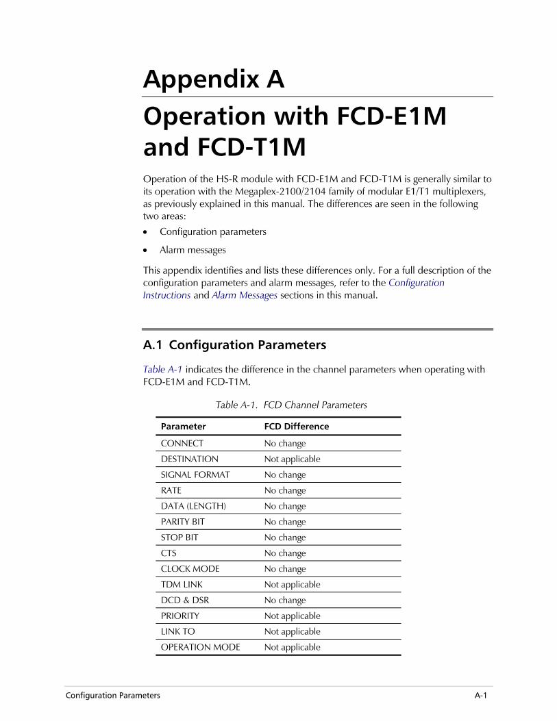
A.1 Configuration Parameters
Table A-1 indicates the difference in the channel parameters when operating with FCD-E1M and FCD-T1M.
Table A-1. FCD Channel Parameters
Parameter FCD Difference
CONNECT No change
DESTINATION Not applicable
SIGNAL FORMAT No change
RATE No change
DATA (LENGTH) No change
PARITY BIT No change
STOP BIT No change
CTS No change
CLOCK MODE No change
TDM LINK Not applicable
DCD & DSR No change
PRIORITY Not applicable
LINK TO Not applicable
OPERATION MODE Not applicable
Operation with FCD-E1M and FCD-T1M MP-2100 HS-R Installation and Operation Manual
A-2 Alarm Messages
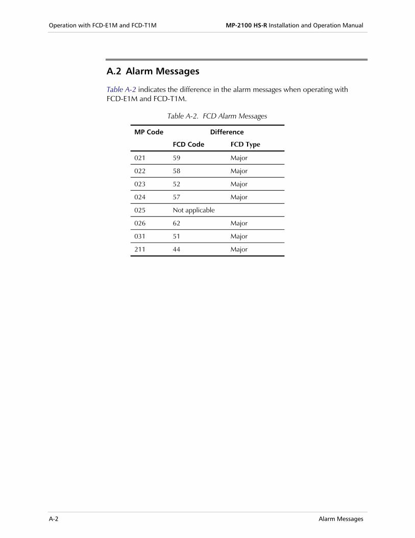
A.2 Alarm Messages
Table A-2 indicates the difference in the alarm messages when operating with FCD-E1M and FCD-T1M.
Table A-2. FCD Alarm Messages
MP Code Difference
FCD Code FCD Type
021 59 Major
022 58 Major
023 52 Major
024 57 Major
025 Not applicable
026 62 Major
031 51 Major
211 44 Major