Embed Size (px)
Citation preview
Technical white paper
HP best practices configuration for Citrix XenDesktop 7 on VMware vSphere 5
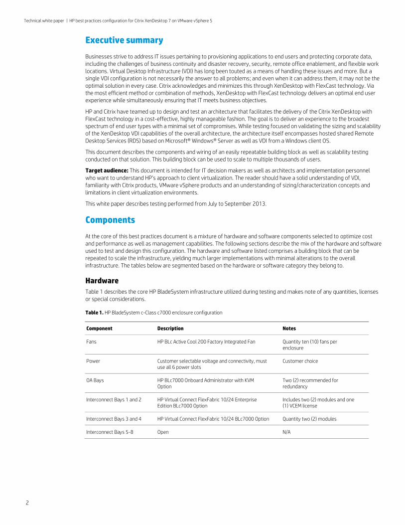
Table of contents Executive summary ...................................................................................................................................................................... 2
Components ................................................................................................................................................................................... 2
Hardware .................................................................................................................................................................................... 2
Software ...................................................................................................................................................................................... 6
Solution structure.......................................................................................................................................................................... 8
Test environment ...................................................................................................................................................................... 8
Architectures .............................................................................................................................................................................. 9
Virtual Connect configuration ............................................................................................................................................... 14
VDI host configuration ........................................................................................................................................................... 18
Summary ....................................................................................................................................................................................... 20
Appendix A – Solution testing ................................................................................................................................................... 20
Single server testing ............................................................................................................................................................... 21
Three server tests ................................................................................................................................................................... 25
Ten server tests ....................................................................................................................................................................... 27
For more information ................................................................................................................................................................. 35
Technical white paper | HP best practices configuration for Citrix XenDesktop 7 on VMware vSphere 5
2
Executive summary
Businesses strive to address IT issues pertaining to provisioning applications to end users and protecting corporate data, including the challenges of business continuity and disaster recovery, security, remote office enablement, and flexible work locations. Virtual Desktop Infrastructure (VDI) has long been touted as a means of handling these issues and more. But a single VDI configuration is not necessarily the answer to all problems; and even when it can address them, it may not be the optimal solution in every case. Citrix acknowledges and minimizes this through XenDesktop with FlexCast technology. Via the most efficient method or combination of methods, XenDesktop with FlexCast technology delivers an optimal end user experience while simultaneously ensuring that IT meets business objectives.
HP and Citrix have teamed up to design and test an architecture that facilitates the delivery of the Citrix XenDesktop with FlexCast technology in a cost-effective, highly manageable fashion. The goal is to deliver an experience to the broadest spectrum of end user types with a minimal set of compromises. While testing focused on validating the sizing and scalability of the XenDesktop VDI capabilities of the overall architecture, the architecture itself encompasses hosted shared Remote Desktop Services (RDS) based on Microsoft® Windows® Server as well as VDI from a Windows client OS.
This document describes the components and wiring of an easily repeatable building block as well as scalability testing conducted on that solution. This building block can be used to scale to multiple thousands of users.
Target audience: This document is intended for IT decision makers as well as architects and implementation personnel who want to understand HP’s approach to client virtualization. The reader should have a solid understanding of VDI, familiarity with Citrix products, VMware vSphere products and an understanding of sizing/characterization concepts and limitations in client virtualization environments.
This white paper describes testing performed from July to September 2013.
Components
At the core of this best practices document is a mixture of hardware and software components selected to optimize cost and performance as well as management capabilities. The following sections describe the mix of the hardware and software used to test and design this configuration. The hardware and software listed comprises a building block that can be repeated to scale the infrastructure, yielding much larger implementations with minimal alterations to the overall infrastructure. The tables below are segmented based on the hardware or software category they belong to.
Hardware
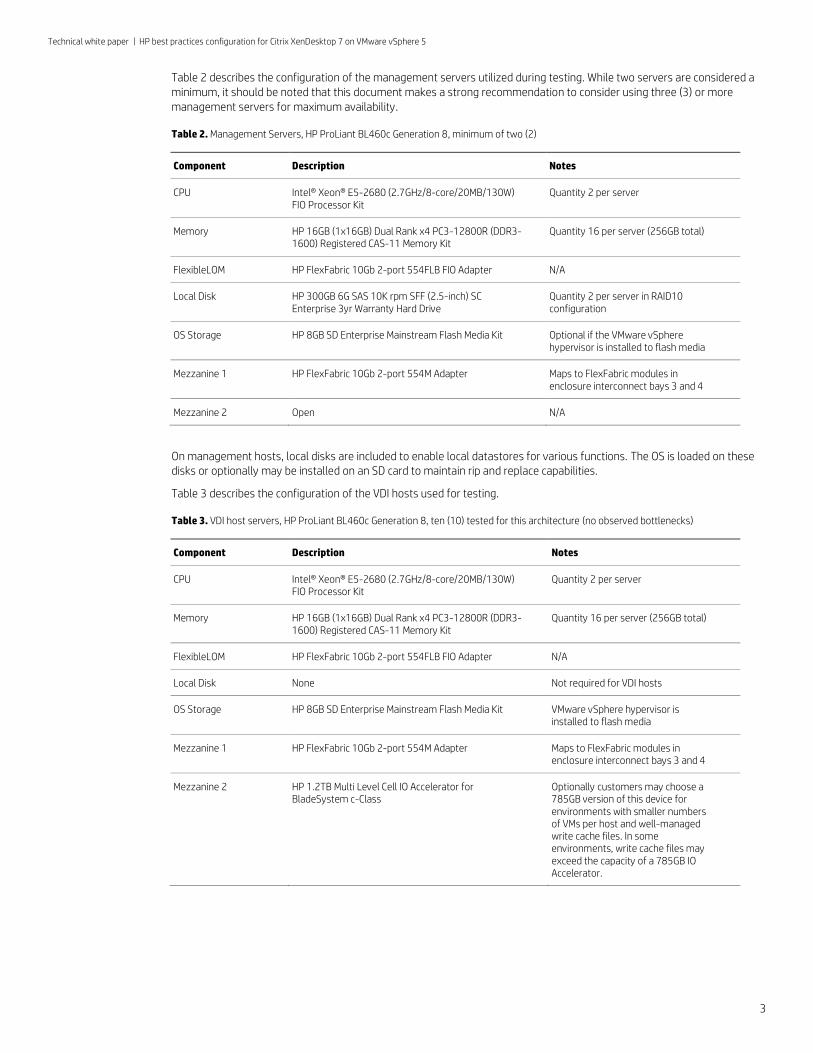
Table 1 describes the core HP BladeSystem infrastructure utilized during testing and makes note of any quantities, licenses or special considerations.
Table 1. HP BladeSystem c-Class c7000 enclosure configuration
Component Description Notes
Fans HP BLc Active Cool 200 Factory Integrated Fan Quantity ten (10) fans per enclosure
Power Customer selectable voltage and connectivity, must use all 6 power slots
Customer choice
OA Bays HP BLc7000 Onboard Administrator with KVM Option
Two (2) recommended for redundancy
Interconnect Bays 1 and 2 HP Virtual Connect FlexFabric 10/24 Enterprise Edition BLc7000 Option
Includes two (2) modules and one (1) VCEM license
Interconnect Bays 3 and 4 HP Virtual Connect FlexFabric 10/24 BLc7000 Option Quantity two (2) modules
Interconnect Bays 5-8 Open N/A
Technical white paper | HP best practices configuration for Citrix XenDesktop 7 on VMware vSphere 5
3
Table 2 describes the configuration of the management servers utilized during testing. While two servers are considered a minimum, it should be noted that this document makes a strong recommendation to consider using three (3) or more management servers for maximum availability.
Table 2. Management Servers, HP ProLiant BL460c Generation 8, minimum of two (2)
Component Description Notes
CPU Intel® Xeon® E5-2680 (2.7GHz/8-core/20MB/130W) FIO Processor Kit
Quantity 2 per server
Memory HP 16GB (1x16GB) Dual Rank x4 PC3-12800R (DDR3-1600) Registered CAS-11 Memory Kit
Quantity 16 per server (256GB total)
FlexibleLOM HP FlexFabric 10Gb 2-port 554FLB FIO Adapter N/A
Local Disk HP 300GB 6G SAS 10K rpm SFF (2.5-inch) SC Enterprise 3yr Warranty Hard Drive
Quantity 2 per server in RAID10 configuration
OS Storage HP 8GB SD Enterprise Mainstream Flash Media Kit Optional if the VMware vSphere hypervisor is installed to flash media
Mezzanine 1 HP FlexFabric 10Gb 2-port 554M Adapter Maps to FlexFabric modules in enclosure interconnect bays 3 and 4
Mezzanine 2 Open N/A
On management hosts, local disks are included to enable local datastores for various functions. The OS is loaded on these disks or optionally may be installed on an SD card to maintain rip and replace capabilities.
Table 3 describes the configuration of the VDI hosts used for testing.
Table 3. VDI host servers, HP ProLiant BL460c Generation 8, ten (10) tested for this architecture (no observed bottlenecks)
Component Description Notes
CPU Intel® Xeon® E5-2680 (2.7GHz/8-core/20MB/130W) FIO Processor Kit
Quantity 2 per server
Memory HP 16GB (1x16GB) Dual Rank x4 PC3-12800R (DDR3-1600) Registered CAS-11 Memory Kit
Quantity 16 per server (256GB total)
FlexibleLOM HP FlexFabric 10Gb 2-port 554FLB FIO Adapter N/A
Local Disk None Not required for VDI hosts
OS Storage HP 8GB SD Enterprise Mainstream Flash Media Kit VMware vSphere hypervisor is installed to flash media
Mezzanine 1 HP FlexFabric 10Gb 2-port 554M Adapter Maps to FlexFabric modules in enclosure interconnect bays 3 and 4
Mezzanine 2 HP 1.2TB Multi Level Cell IO Accelerator for BladeSystem c-Class
Optionally customers may choose a 785GB version of this device for environments with smaller numbers of VMs per host and well-managed write cache files. In some environments, write cache files may exceed the capacity of a 785GB IO Accelerator.
Technical white paper | HP best practices configuration for Citrix XenDesktop 7 on VMware vSphere 5
4
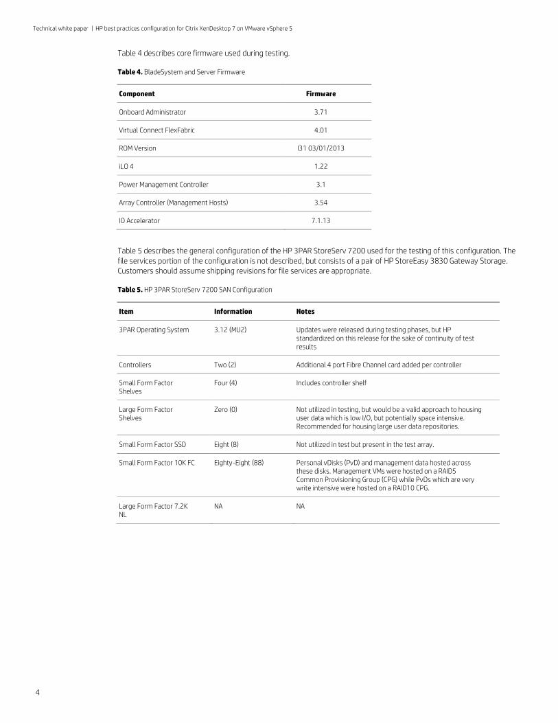
Table 4 describes core firmware used during testing.
Table 4. BladeSystem and Server Firmware
Component Firmware
Onboard Administrator 3.71
Virtual Connect FlexFabric 4.01
ROM Version I31 03/01/2013
iLO 4 1.22
Power Management Controller 3.1
Array Controller (Management Hosts) 3.54
IO Accelerator 7.1.13
Table 5 describes the general configuration of the HP 3PAR StoreServ 7200 used for the testing of this configuration. The file services portion of the configuration is not described, but consists of a pair of HP StoreEasy 3830 Gateway Storage. Customers should assume shipping revisions for file services are appropriate.
Table 5. HP 3PAR StoreServ 7200 SAN Configuration
Item Information Notes
3PAR Operating System 3.12 (MU2) Updates were released during testing phases, but HP standardized on this release for the sake of continuity of test results
Controllers Two (2) Additional 4 port Fibre Channel card added per controller
Small Form Factor Shelves
Four (4) Includes controller shelf
Large Form Factor Shelves
Zero (0) Not utilized in testing, but would be a valid approach to housing user data which is low I/O, but potentially space intensive. Recommended for housing large user data repositories.
Small Form Factor SSD Eight (8) Not utilized in test but present in the test array.
Small Form Factor 10K FC Eighty-Eight (88) Personal vDisks (PvD) and management data hosted across these disks. Management VMs were hosted on a RAID5 Common Provisioning Group (CPG) while PvDs which are very write intensive were hosted on a RAID10 CPG.
Large Form Factor 7.2K NL
NA NA
Technical white paper | HP best practices configuration for Citrix XenDesktop 7 on VMware vSphere 5
5
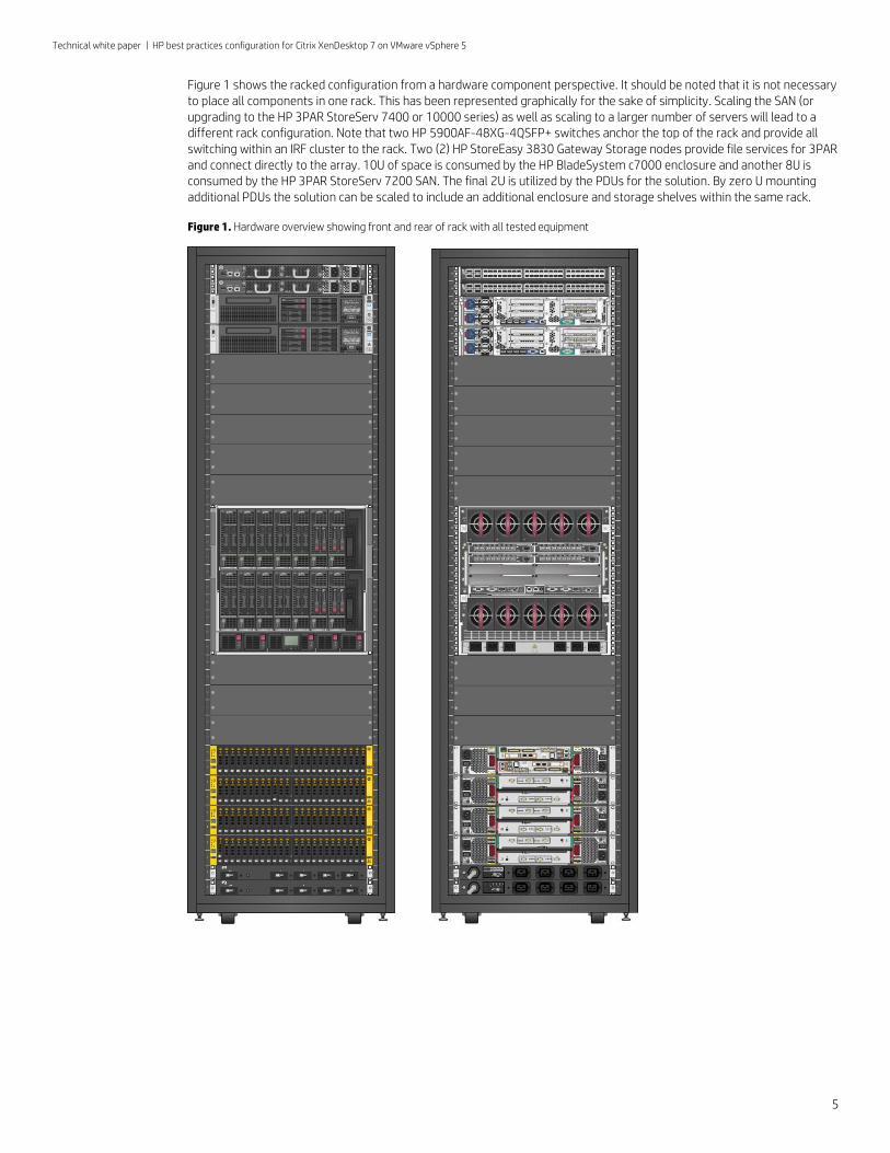
Figure 1 shows the racked configuration from a hardware component perspective. It should be noted that it is not necessary to place all components in one rack. This has been represented graphically for the sake of simplicity. Scaling the SAN (or upgrading to the HP 3PAR StoreServ 7400 or 10000 series) as well as scaling to a larger number of servers will lead to a different rack configuration. Note that two HP 5900AF-48XG-4QSFP+ switches anchor the top of the rack and provide all switching within an IRF cluster to the rack. Two (2) HP StoreEasy 3830 Gateway Storage nodes provide file services for 3PAR and connect directly to the array. 10U of space is consumed by the HP BladeSystem c7000 enclosure and another 8U is consumed by the HP 3PAR StoreServ 7200 SAN. The final 2U is utilized by the PDUs for the solution. By zero U mounting additional PDUs the solution can be scaled to include an additional enclosure and storage shelves within the same rack.
Figure 1. Hardware overview showing front and rear of rack with all tested equipment
Technical white paper | HP best practices configuration for Citrix XenDesktop 7 on VMware vSphere 5
6
Software
All VMware management VMs were installed on Microsoft Windows Server 2008 R2, Service Pack 1 with all patches applied to August 8th, 2013. No further patches were applied during testing for sake of continuity. .NET Framework 3.5 SP1 was installed on all management VMs as a standard test lab practice, and any specific version upgrades required by the individual management pieces were also installed. Citrix software based virtual machines were installed on Microsoft Windows Server 2012.
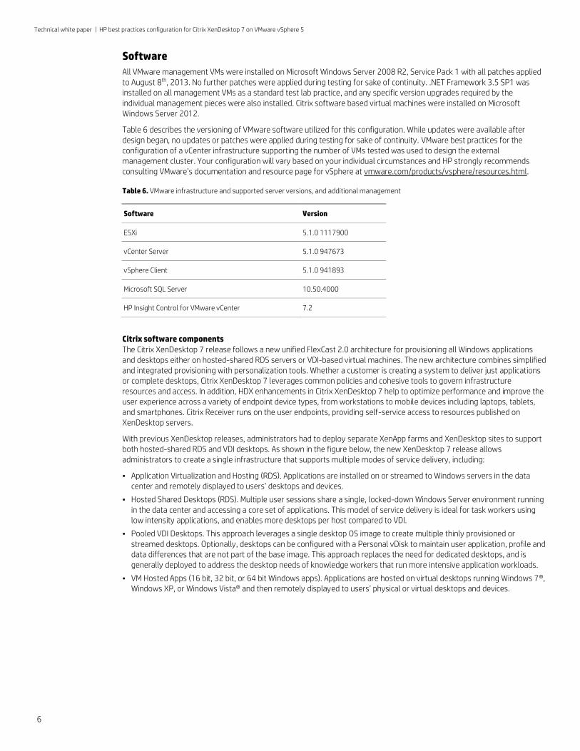
Table 6 describes the versioning of VMware software utilized for this configuration. While updates were available after design began, no updates or patches were applied during testing for sake of continuity. VMware best practices for the configuration of a vCenter infrastructure supporting the number of VMs tested was used to design the external management cluster. Your configuration will vary based on your individual circumstances and HP strongly recommends consulting VMware’s documentation and resource page for vSphere at vmware.com/products/vsphere/resources.html.
Table 6. VMware infrastructure and supported server versions, and additional management
Software Version
ESXi 5.1.0 1117900
vCenter Server 5.1.0 947673
vSphere Client 5.1.0 941893
Microsoft SQL Server 10.50.4000
HP Insight Control for VMware vCenter 7.2
Citrix software components The Citrix XenDesktop 7 release follows a new unified FlexCast 2.0 architecture for provisioning all Windows applications and desktops either on hosted-shared RDS servers or VDI-based virtual machines. The new architecture combines simplified and integrated provisioning with personalization tools. Whether a customer is creating a system to deliver just applications or complete desktops, Citrix XenDesktop 7 leverages common policies and cohesive tools to govern infrastructure resources and access. In addition, HDX enhancements in Citrix XenDesktop 7 help to optimize performance and improve the user experience across a variety of endpoint device types, from workstations to mobile devices including laptops, tablets, and smartphones. Citrix Receiver runs on the user endpoints, providing self-service access to resources published on XenDesktop servers.
With previous XenDesktop releases, administrators had to deploy separate XenApp farms and XenDesktop sites to support both hosted-shared RDS and VDI desktops. As shown in the figure below, the new XenDesktop 7 release allows administrators to create a single infrastructure that supports multiple modes of service delivery, including:
• Application Virtualization and Hosting (RDS). Applications are installed on or streamed to Windows servers in the data center and remotely displayed to users’ desktops and devices.
• Hosted Shared Desktops (RDS). Multiple user sessions share a single, locked-down Windows Server environment running in the data center and accessing a core set of applications. This model of service delivery is ideal for task workers using low intensity applications, and enables more desktops per host compared to VDI.
• Pooled VDI Desktops. This approach leverages a single desktop OS image to create multiple thinly provisioned or streamed desktops. Optionally, desktops can be configured with a Personal vDisk to maintain user application, profile and data differences that are not part of the base image. This approach replaces the need for dedicated desktops, and is generally deployed to address the desktop needs of knowledge workers that run more intensive application workloads.
• VM Hosted Apps (16 bit, 32 bit, or 64 bit Windows apps). Applications are hosted on virtual desktops running Windows 7®, Windows XP, or Windows Vista® and then remotely displayed to users’ physical or virtual desktops and devices.
Technical white paper | HP best practices configuration for Citrix XenDesktop 7 on VMware vSphere 5
7
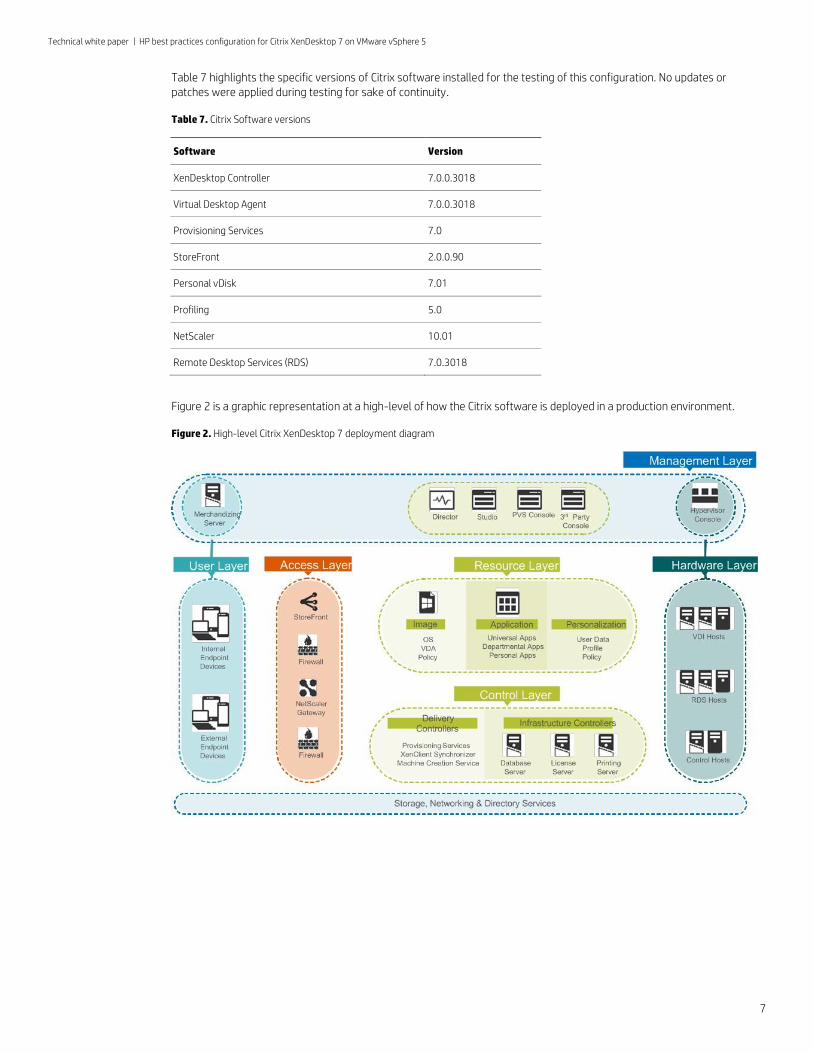
Table 7 highlights the specific versions of Citrix software installed for the testing of this configuration. No updates or patches were applied during testing for sake of continuity.
Table 7. Citrix Software versions
Software Version
XenDesktop Controller 7.0.0.3018
Virtual Desktop Agent 7.0.0.3018
Provisioning Services 7.0
StoreFront 2.0.0.90
Personal vDisk 7.01
Profiling 5.0
NetScaler 10.01
Remote Desktop Services (RDS) 7.0.3018
Figure 2 is a graphic representation at a high-level of how the Citrix software is deployed in a production environment.
Figure 2. High-level Citrix XenDesktop 7 deployment diagram
Technical white paper | HP best practices configuration for Citrix XenDesktop 7 on VMware vSphere 5
8
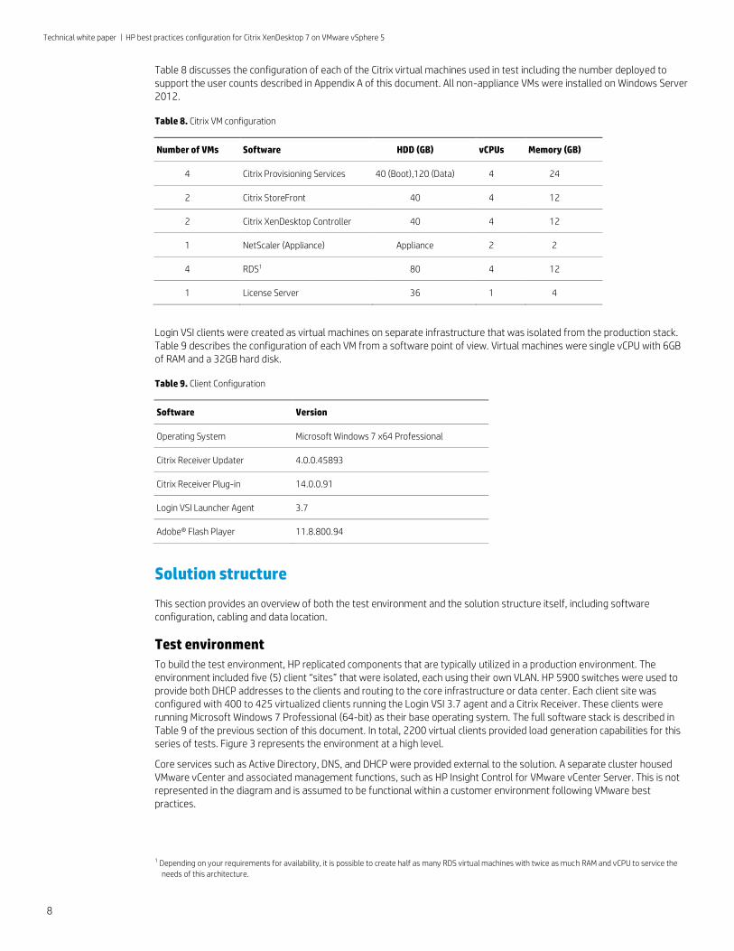
Table 8 discusses the configuration of each of the Citrix virtual machines used in test including the number deployed to support the user counts described in Appendix A of this document. All non-appliance VMs were installed on Windows Server 2012.
Table 8. Citrix VM configuration
Number of VMs Software HDD (GB) vCPUs Memory (GB)
4 Citrix Provisioning Services 40 (Boot),120 (Data) 4 24
2 Citrix StoreFront 40 4 12
2 Citrix XenDesktop Controller 40 4 12
1 NetScaler (Appliance) Appliance 2 2
4 RDS1 80 4 12
1 License Server 36 1 4
Login VSI clients were created as virtual machines on separate infrastructure that was isolated from the production stack. Table 9 describes the configuration of each VM from a software point of view. Virtual machines were single vCPU with 6GB of RAM and a 32GB hard disk.
Table 9. Client Configuration
Software Version
Operating System Microsoft Windows 7 x64 Professional
Citrix Receiver Updater 4.0.0.45893
Citrix Receiver Plug-in 14.0.0.91
Login VSI Launcher Agent 3.7
Adobe® Flash Player 11.8.800.94
Solution structure
This section provides an overview of both the test environment and the solution structure itself, including software configuration, cabling and data location.
Test environment
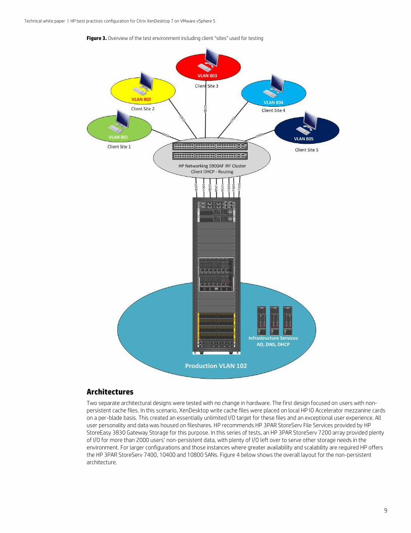
To build the test environment, HP replicated components that are typically utilized in a production environment. The environment included five (5) client “sites” that were isolated, each using their own VLAN. HP 5900 switches were used to provide both DHCP addresses to the clients and routing to the core infrastructure or data center. Each client site was configured with 400 to 425 virtualized clients running the Login VSI 3.7 agent and a Citrix Receiver. These clients were running Microsoft Windows 7 Professional (64-bit) as their base operating system. The full software stack is described in Table 9 of the previous section of this document. In total, 2200 virtual clients provided load generation capabilities for this series of tests. Figure 3 represents the environment at a high level.
Core services such as Active Directory, DNS, and DHCP were provided external to the solution. A separate cluster housed VMware vCenter and associated management functions, such as HP Insight Control for VMware vCenter Server. This is not represented in the diagram and is assumed to be functional within a customer environment following VMware best practices.
1 Depending on your requirements for availability, it is possible to create half as many RDS virtual machines with twice as much RAM and vCPU to service the
needs of this architecture.
Technical white paper | HP best practices configuration for Citrix XenDesktop 7 on VMware vSphere 5
9
Figure 3. Overview of the test environment including client “sites” used for testing
Architectures
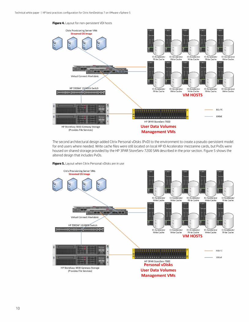
Two separate architectural designs were tested with no change in hardware. The first design focused on users with non-persistent cache files. In this scenario, XenDesktop write cache files were placed on local HP IO Accelerator mezzanine cards on a per-blade basis. This created an essentially unlimited I/O target for these files and an exceptional user experience. All user personality and data was housed on fileshares. HP recommends HP 3PAR StoreServ File Services provided by HP StoreEasy 3830 Gateway Storage for this purpose. In this series of tests, an HP 3PAR StoreServ 7200 array provided plenty of I/O for more than 2000 users’ non-persistent data, with plenty of I/O left over to serve other storage needs in the environment. For larger configurations and those instances where greater availability and scalability are required HP offers the HP 3PAR StoreServ 7400, 10400 and 10800 SANs. Figure 4 below shows the overall layout for the non-persistent architecture.
Technical white paper | HP best practices configuration for Citrix XenDesktop 7 on VMware vSphere 5
10
Figure 4. Layout for non-persistent VDI hosts
The second architectural design added Citrix Personal vDisks (PvD) to the environment to create a pseudo-persistent model for end users where needed. Write cache files were still located on local HP IO Accelerator mezzanine cards, but PvDs were housed on shared storage provided by the HP 3PAR StoreServ 7200 SAN described in the prior section. Figure 5 shows the altered design that includes PvDs.
Figure 5. Layout when Citrix Personal vDisks are in use
Technical white paper | HP best practices configuration for Citrix XenDesktop 7 on VMware vSphere 5
11
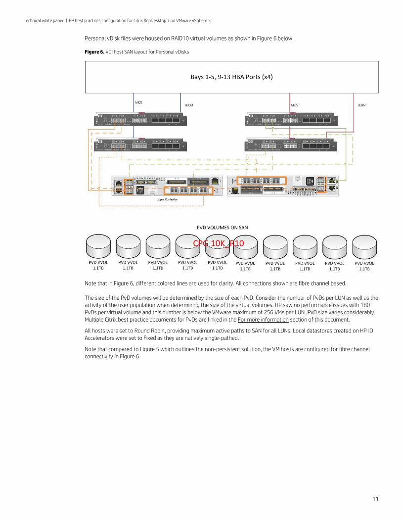
Personal vDisk files were housed on RAID10 virtual volumes as shown in Figure 6 below.
Figure 6. VDI host SAN layout for Personal vDisks
Note that in Figure 6, different colored lines are used for clarity. All connections shown are fibre channel based.
The size of the PvD volumes will be determined by the size of each PvD. Consider the number of PvDs per LUN as well as the activity of the user population when determining the size of the virtual volumes. HP saw no performance issues with 180 PvDs per virtual volume and this number is below the VMware maximum of 256 VMs per LUN. PvD size varies considerably. Multiple Citrix best practice documents for PvDs are linked in the For more information section of this document.
All hosts were set to Round Robin, providing maximum active paths to SAN for all LUNs. Local datastores created on HP IO Accelerators were set to Fixed as they are natively single-pathed.
Note that compared to Figure 5 which outlines the non-persistent solution, the VM hosts are configured for fibre channel connectivity in Figure 6.
Technical white paper | HP best practices configuration for Citrix XenDesktop 7 on VMware vSphere 5
12
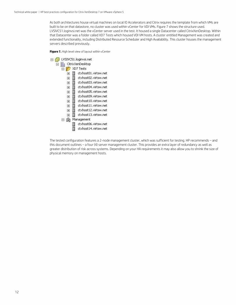
As both architectures house virtual machines on local IO Accelerators and Citrix requires the template from which VMs are built to be on that datastore, no cluster was used within vCenter for VDI VMs. Figure 7 shows the structure used. LVSIVC51.loginvsi.net was the vCenter server used in the test. It housed a single Datacenter called CitrixXenDesktop. Within that Datacenter was a folder called XD7 Tests which housed VDI VM hosts. A cluster entitled Management was created and extended functionality, including Distributed Resource Scheduler and High Availability. This cluster houses the management servers described previously.
Figure 7. High level view of layout within vCenter
The tested configuration features a 2-node management cluster, which was sufficient for testing. HP recommends – and this document outlines – a four (4) server management cluster. This provides an extra layer of redundancy as well as greater distribution of risk across systems. Depending on your HA requirements it may also allow you to shrink the size of physical memory on management hosts.
Technical white paper | HP best practices configuration for Citrix XenDesktop 7 on VMware vSphere 5
13
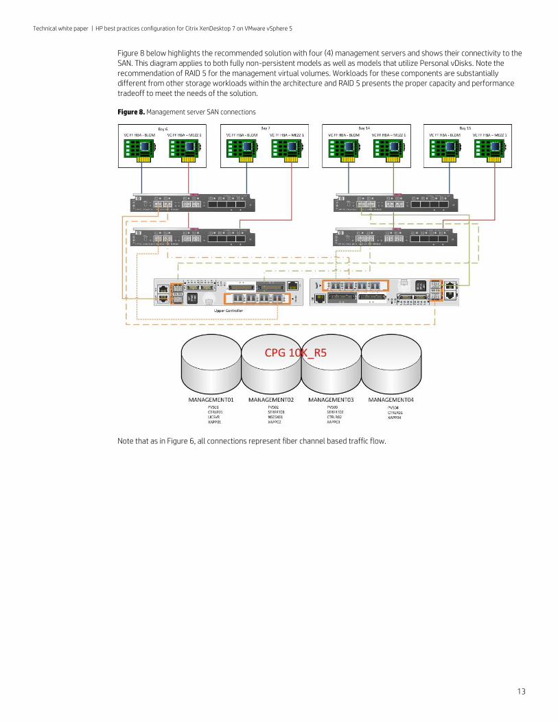
Figure 8 below highlights the recommended solution with four (4) management servers and shows their connectivity to the SAN. This diagram applies to both fully non-persistent models as well as models that utilize Personal vDisks. Note the recommendation of RAID 5 for the management virtual volumes. Workloads for these components are substantially different from other storage workloads within the architecture and RAID 5 presents the proper capacity and performance tradeoff to meet the needs of the solution.
Figure 8. Management server SAN connections
Note that as in Figure 6, all connections represent fiber channel based traffic flow.
Technical white paper | HP best practices configuration for Citrix XenDesktop 7 on VMware vSphere 5
14
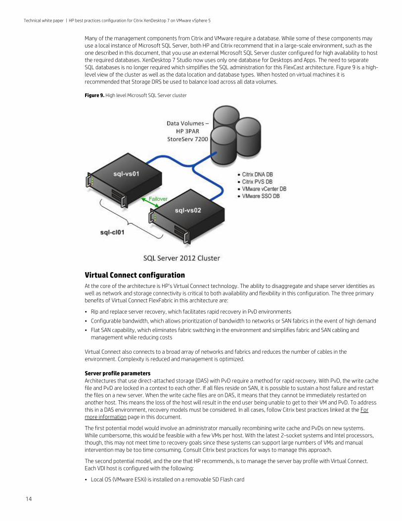
Many of the management components from Citrix and VMware require a database. While some of these components may use a local instance of Microsoft SQL Server, both HP and Citrix recommend that in a large-scale environment, such as the one described in this document, that you use an external Microsoft SQL Server cluster configured for high availability to host the required databases. XenDesktop 7 Studio now uses only one database for Desktops and Apps. The need to separate SQL databases is no longer required which simplifies the SQL administration for this FlexCast architecture. Figure 9 is a high-level view of the cluster as well as the data location and database types. When hosted on virtual machines it is recommended that Storage DRS be used to balance load across all data volumes.
Figure 9. High level Microsoft SQL Server cluster
Virtual Connect configuration
At the core of the architecture is HP’s Virtual Connect technology. The ability to disaggregate and shape server identities as well as network and storage connectivity is critical to both availability and flexibility in this configuration. The three primary benefits of Virtual Connect FlexFabric in this architecture are:
• Rip and replace server recovery, which facilitates rapid recovery in PvD environments
• Configurable bandwidth, which allows prioritization of bandwidth to networks or SAN fabrics in the event of high demand
• Flat SAN capability, which eliminates fabric switching in the environment and simplifies fabric and SAN cabling and management while reducing costs
Virtual Connect also connects to a broad array of networks and fabrics and reduces the number of cables in the environment. Complexity is reduced and management is optimized.
Server profile parameters
Architectures that use direct-attached storage (DAS) with PvD require a method for rapid recovery. With PvD, the write cache file and PvD are locked in a context to each other. If all files reside on SAN, it is possible to sustain a host failure and restart the files on a new server. When the write cache files are on DAS, it means that they cannot be immediately restarted on another host. This means the loss of the host will result in the end user being unable to get to their VM and PvD. To address this in a DAS environment, recovery models must be considered. In all cases, follow Citrix best practices linked at the For more information page in this document.
The first potential model would involve an administrator manually recombining write cache and PvDs on new systems. While cumbersome, this would be feasible with a few VMs per host. With the latest 2-socket systems and Intel processors, though, this may not meet time to recovery goals since these systems can support large numbers of VMs and manual intervention may be too time consuming. Consult Citrix best practices for ways to manage this approach.
The second potential model, and the one that HP recommends, is to manage the server bay profile with Virtual Connect. Each VDI host is configured with the following:
• Local OS (VMware ESXi) is installed on a removable SD Flash card
Technical white paper | HP best practices configuration for Citrix XenDesktop 7 on VMware vSphere 5
15
• Virtual Connect assigns the serial number to the server
• Virtual Connect assigns MAC addresses to all NICs
• Virtual Connect assigns WWIDs to all HBA functions
The combination of these parameters creates a rip and replace host. In the event of a failure, the SD card is moved to a new system (two open bays per enclosure are free to hold excess capacity) and the Virtual Connect profile of the failed server is pointed at the new server. Upon boot, the new server is seen as the original system.
In addition to these parameters, each host must be configured for networking and SAN fabrics. Those parameters are discussed in the following sections.
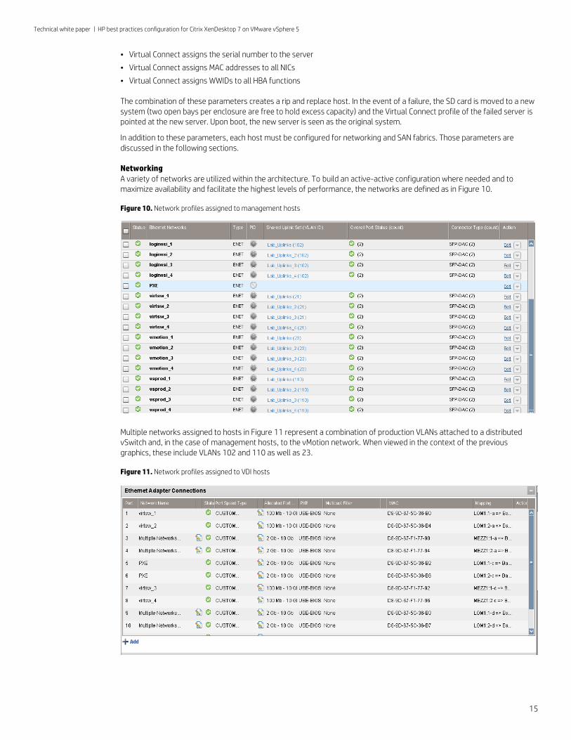
Networking
A variety of networks are utilized within the architecture. To build an active-active configuration where needed and to maximize availability and facilitate the highest levels of performance, the networks are defined as in Figure 10.
Figure 10. Network profiles assigned to management hosts
Multiple networks assigned to hosts in Figure 11 represent a combination of production VLANs attached to a distributed vSwitch and, in the case of management hosts, to the vMotion network. When viewed in the context of the previous graphics, these include VLANs 102 and 110 as well as 23.
Figure 11. Network profiles assigned to VDI hosts
Technical white paper | HP best practices configuration for Citrix XenDesktop 7 on VMware vSphere 5
16
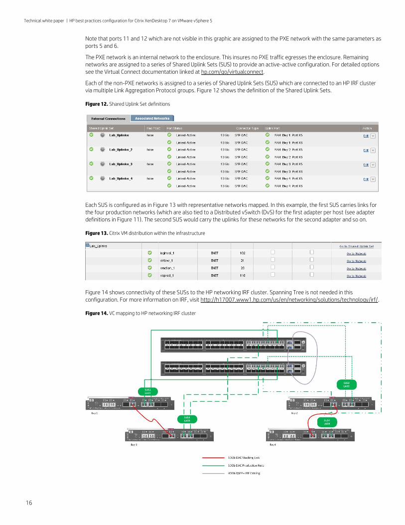
Note that ports 11 and 12 which are not visible in this graphic are assigned to the PXE network with the same parameters as ports 5 and 6.
The PXE network is an internal network to the enclosure. This insures no PXE traffic egresses the enclosure. Remaining networks are assigned to a series of Shared Uplink Sets (SUS) to provide an active-active configuration. For detailed options see the Virtual Connect documentation linked at hp.com/go/virtualconnect.
Each of the non-PXE networks is assigned to a series of Shared Uplink Sets (SUS) which are connected to an HP IRF cluster via multiple Link Aggregation Protocol groups. Figure 12 shows the definition of the Shared Uplink Sets.
Figure 12. Shared Uplink Set definitions
Each SUS is configured as in Figure 13 with representative networks mapped. In this example, the first SUS carries links for the four production networks (which are also tied to a Distributed vSwitch (DvS) for the first adapter per host (see adapter definitions in Figure 11). The second SUS would carry the uplinks for these networks for the second adapter and so on.
Figure 13. Citrix VM distribution within the infrastructure
Figure 14 shows connectivity of these SUSs to the HP networking IRF cluster. Spanning Tree is not needed in this configuration. For more information on IRF, visit http://h17007.www1.hp.com/us/en/networking/solutions/technology/irf/.
Figure 14. VC mapping to HP networking IRF cluster
Technical white paper | HP best practices configuration for Citrix XenDesktop 7 on VMware vSphere 5
17
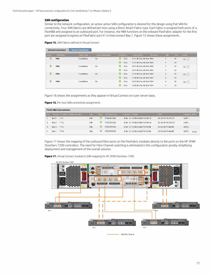
SAN configuration
Similar to the network configuration, an active-active SAN configuration is desired for this design using Flat SAN for connectivity. Four SAN fabrics are defined per host using a Direct Attach Fabric type. Each fabric is assigned both ports of a FlexHBA and assigned to an outbound port. For instance, the HBA functions on the onboard FlexFabric adapter for the first port are assigned to egress on FlexFabric port X1 in Interconnect Bay 1. Figure 15 shows these assignments.
Figure 15. SAN Fabrics defined in Virtual Connect
Figure 16 shows the assignments as they appear in Virtual Connect on a per server basis.
Figure 16. Per host SAN connectivity assignments
Figure 17 shows the mapping of the outbound fibre ports on the FlexFabric modules directly to the ports on the HP 3PAR StoreServ 7200 controllers. The need for Fibre Channel switching is eliminated in this configuration greatly simplifying deployment and management of the overall solution.
Figure 17. Virtual Connect module to SAN mapping for HP 3PAR StoreServ 7200
Technical white paper | HP best practices configuration for Citrix XenDesktop 7 on VMware vSphere 5
18
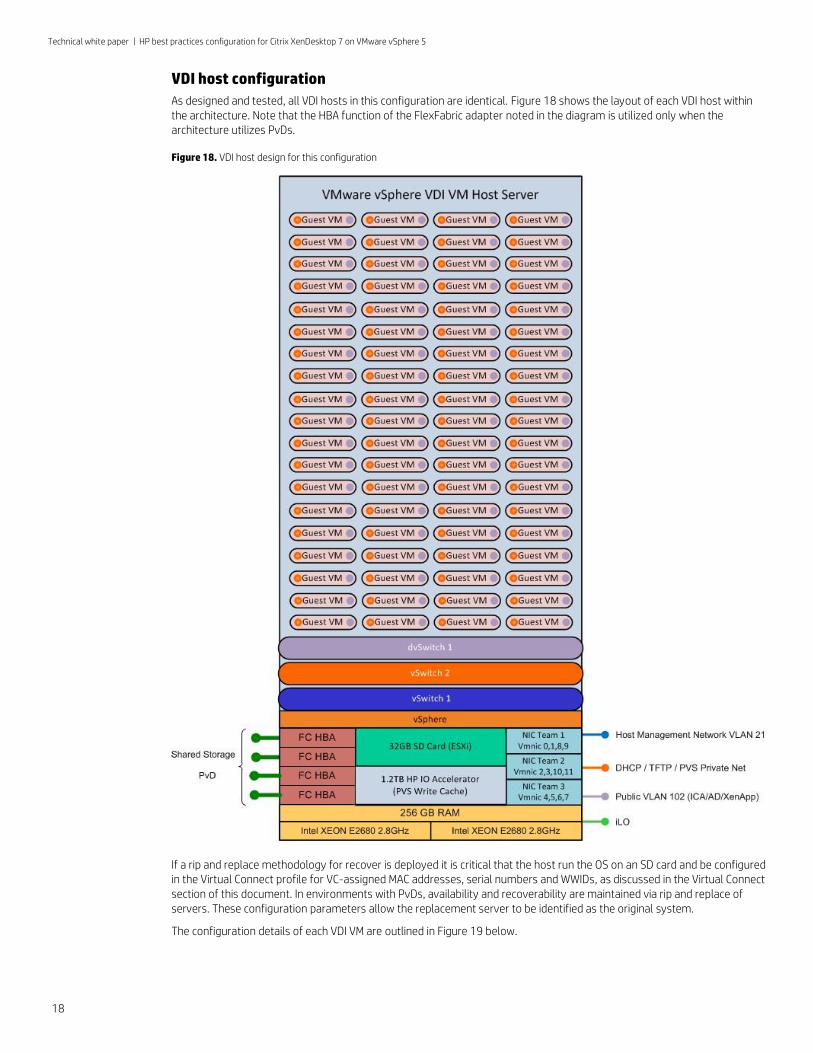
VDI host configuration
As designed and tested, all VDI hosts in this configuration are identical. Figure 18 shows the layout of each VDI host within the architecture. Note that the HBA function of the FlexFabric adapter noted in the diagram is utilized only when the architecture utilizes PvDs.
Figure 18. VDI host design for this configuration
If a rip and replace methodology for recover is deployed it is critical that the host run the OS on an SD card and be configured in the Virtual Connect profile for VC-assigned MAC addresses, serial numbers and WWIDs, as discussed in the Virtual Connect section of this document. In environments with PvDs, availability and recoverability are maintained via rip and replace of servers. These configuration parameters allow the replacement server to be identified as the original system.
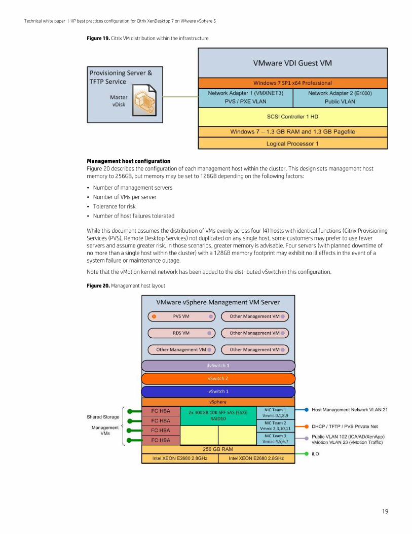
The configuration details of each VDI VM are outlined in Figure 19 below.
Technical white paper | HP best practices configuration for Citrix XenDesktop 7 on VMware vSphere 5
19
Figure 19. Citrix VM distribution within the infrastructure
Management host configuration Figure 20 describes the configuration of each management host within the cluster. This design sets management host memory to 256GB, but memory may be set to 128GB depending on the following factors:
• Number of management servers
• Number of VMs per server
• Tolerance for risk
• Number of host failures tolerated
While this document assumes the distribution of VMs evenly across four (4) hosts with identical functions (Citrix Provisioning Services (PVS), Remote Desktop Services) not duplicated on any single host, some customers may prefer to use fewer servers and assume greater risk. In those scenarios, greater memory is advisable. Four servers (with planned downtime of no more than a single host within the cluster) with a 128GB memory footprint may exhibit no ill effects in the event of a system failure or maintenance outage.
Note that the vMotion kernel network has been added to the distributed vSwitch in this configuration.
Figure 20. Management host layout
Technical white paper | HP best practices configuration for Citrix XenDesktop 7 on VMware vSphere 5
20
Summary
HP and Citrix have created and tested a highly scalable architecture for delivering a highly performant compute experience to a broad group of end users. The tested solution represents a building block that can be multiplied to scale the number of supported users. In testing performed by HP and Citrix (described in the following appendix), the solution scaled well to approximately 2000 users.
Appendix A – Solution testing
HP and Citrix jointly tested the configuration described in this document between July and August of 2013. Load was generated using Login VSI’s Login VSI tool, version 3.7 (see loginvsi.com). While version 4 became available during solution testing, it was decided that version 3.7 would be used to facilitate more accurate comparisons with past reference architectures. This also avoided a disruptive lab changeover. Login VSI has become a commonly used testing tool for VDI and other server-based computing environments. The tool enables performance testing, comparison, and validation of hardware solutions, following a standardized test suite.
Login VSI version 3.7 works by starting a series of clients that connect remotely to a VDI host (or hosts) via a connection protocol. The clients execute a series of end user actions on that host (or hosts) to simulate the load of actual end users. Response times are measured for a variety of actions within each session. When response times climb above a certain level on average, the test is finalized and a score, called VSImax, is created. VSImax represents the number of users at or below the average response time threshold. The VSImax value indicates the number of users on a system when it has reached saturation, which can vary within the same system. For example, during testing for this document, HP reached Login VSImax numbers ranging from 214 to 221 using client-side Flash rendering and between 202 and 211 for server-side rendering on the same host, with no differences in configuration. LoginVSI workloads do not place a great deal of stress on systems from Adobe Flash content. Testing in your environment should be done to evaluate the efficacy of using client side offload. It is expected that in many cases the benefit will be greater than that described in this document.
HP has traditionally recommended sizing a server with approximately 60-65% of the number of users achieved with the VSImax score. This accounted for HA capacity as well as insuring the servers were not throttled at 100%. As direct attached storage is in use and HA and vMotion are not in use, adjustments to sizing can be made with approximately 80-85% capacity planned for use. All of the sizing information assumes a similar application suite, VM size and user behaviors to the test environment. Actual results will vary based on a number of factors including memory per VM, the number and types of applications, as well as how they are delivered to the end user, processor speeds, and per user I/O. HP always recommends that customers perform a pre-implementation analysis to help understand overall user and application behavior and to assess I/O needs prior to implementing any VDI solution.
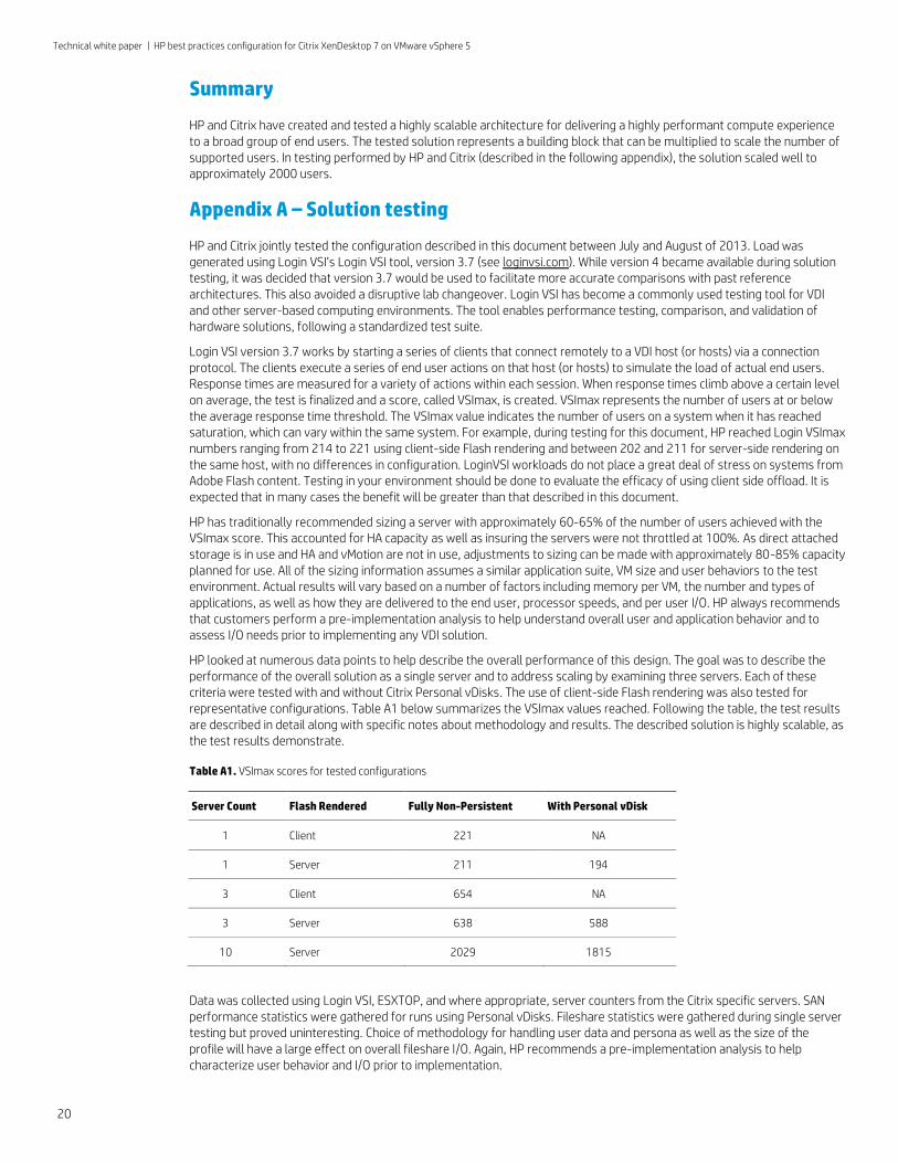
HP looked at numerous data points to help describe the overall performance of this design. The goal was to describe the performance of the overall solution as a single server and to address scaling by examining three servers. Each of these criteria were tested with and without Citrix Personal vDisks. The use of client-side Flash rendering was also tested for representative configurations. Table A1 below summarizes the VSImax values reached. Following the table, the test results are described in detail along with specific notes about methodology and results. The described solution is highly scalable, as the test results demonstrate.
Table A1. VSImax scores for tested configurations
Server Count Flash Rendered Fully Non-Persistent With Personal vDisk
1 Client 221 NA
1 Server 211 194
3 Client 654 NA
3 Server 638 588
10 Server 2029 1815
Data was collected using Login VSI, ESXTOP, and where appropriate, server counters from the Citrix specific servers. SAN performance statistics were gathered for runs using Personal vDisks. Fileshare statistics were gathered during single server testing but proved uninteresting. Choice of methodology for handling user data and persona as well as the size of the profile will have a large effect on overall fileshare I/O. Again, HP recommends a pre-implementation analysis to help characterize user behavior and I/O prior to implementation.
Technical white paper | HP best practices configuration for Citrix XenDesktop 7 on VMware vSphere 5
21
Single server testing
HP and Citrix tested one server within the BladeSystem c7000 chassis outlined in this document. That system was an HP ProLiant BL460c Generation 8 server with the following components:
• Two (2) Intel Xeon E5-2680 Eight (8) Core Processors running at 2.7GHz (Hyper-Threading enabled)
• 256GB of HP Dual Rank x4 PC3-12800R DDR3 1600 Unbuffered Memory
• No local disks. ESXi was installed on local SD media within the server
• HP 1.2TB MLC IO Accelerator
The ROM Based Setup Utility (RBSU) for the system was set to defaults with the exception of changing to mix Balanced Power and Performance and Static High Performance mode. This combination in conjunction with environmental improvements yielded approximately 25 extra VMs per host (prior to tuning, Login VSI VSImax scores ranged from 186 to 198).
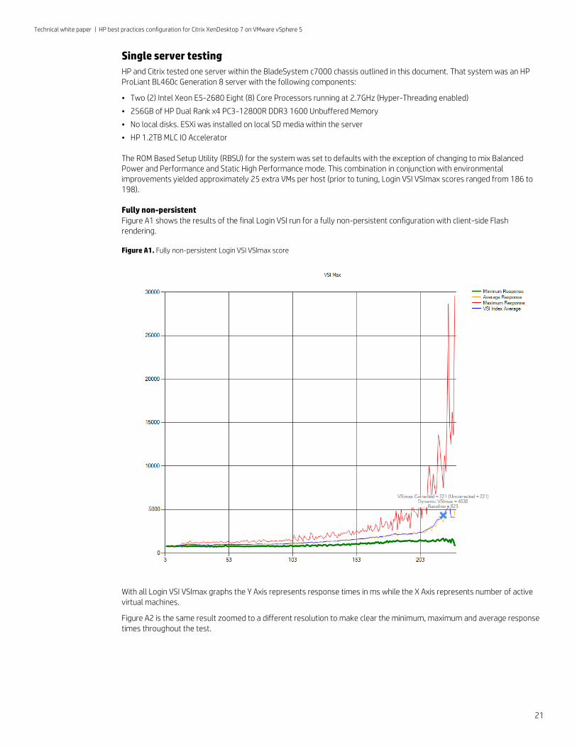
Fully non-persistent
Figure A1 shows the results of the final Login VSI run for a fully non-persistent configuration with client-side Flash rendering.
Figure A1. Fully non-persistent Login VSI VSImax score
With all Login VSI VSImax graphs the Y Axis represents response times in ms while the X Axis represents number of active virtual machines.
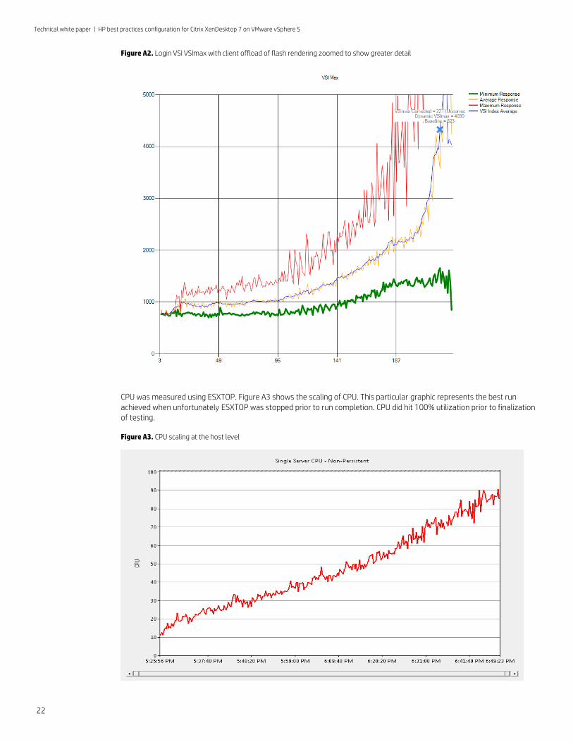
Figure A2 is the same result zoomed to a different resolution to make clear the minimum, maximum and average response times throughout the test.
Technical white paper | HP best practices configuration for Citrix XenDesktop 7 on VMware vSphere 5
22
Figure A2. Login VSI VSImax with client offload of flash rendering zoomed to show greater detail
CPU was measured using ESXTOP. Figure A3 shows the scaling of CPU. This particular graphic represents the best run achieved when unfortunately ESXTOP was stopped prior to run completion. CPU did hit 100% utilization prior to finalization of testing.
Figure A3. CPU scaling at the host level
Technical white paper | HP best practices configuration for Citrix XenDesktop 7 on VMware vSphere 5
23
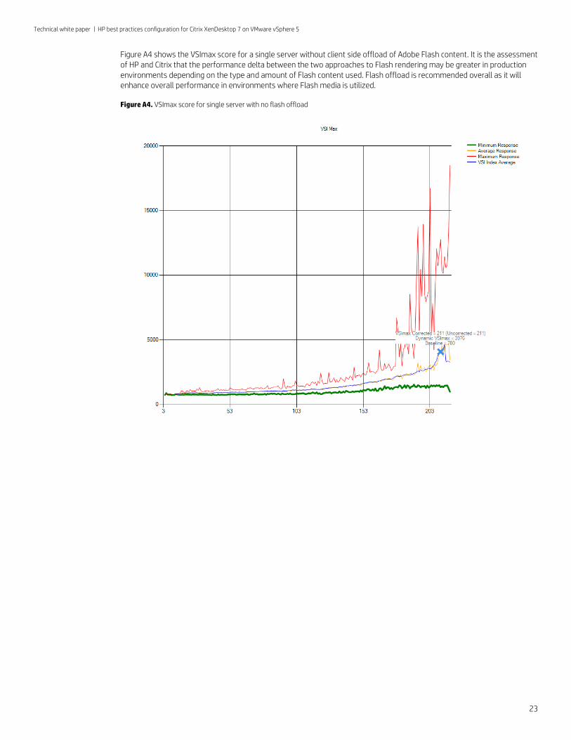
Figure A4 shows the VSImax score for a single server without client side offload of Adobe Flash content. It is the assessment of HP and Citrix that the performance delta between the two approaches to Flash rendering may be greater in production environments depending on the type and amount of Flash content used. Flash offload is recommended overall as it will enhance overall performance in environments where Flash media is utilized.
Figure A4. VSImax score for single server with no flash offload
Technical white paper | HP best practices configuration for Citrix XenDesktop 7 on VMware vSphere 5
24
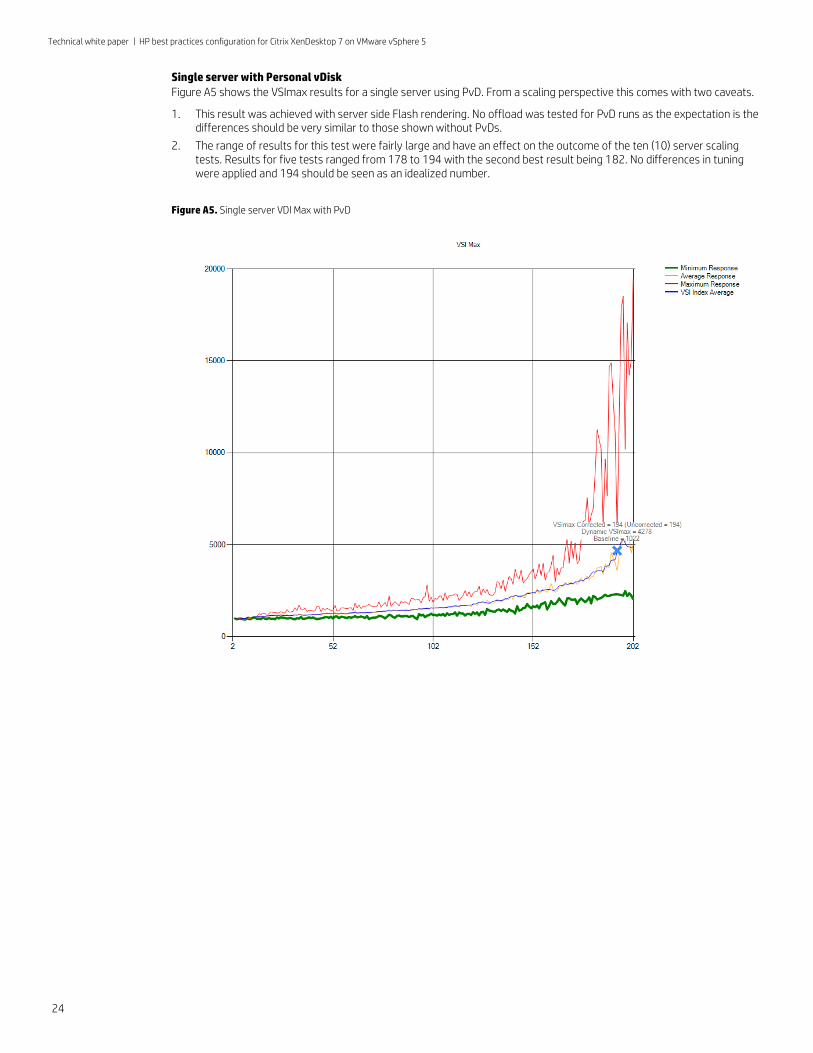
Single server with Personal vDisk
Figure A5 shows the VSImax results for a single server using PvD. From a scaling perspective this comes with two caveats.
1. This result was achieved with server side Flash rendering. No offload was tested for PvD runs as the expectation is the differences should be very similar to those shown without PvDs.
2. The range of results for this test were fairly large and have an effect on the outcome of the ten (10) server scaling tests. Results for five tests ranged from 178 to 194 with the second best result being 182. No differences in tuning were applied and 194 should be seen as an idealized number.
Figure A5. Single server VDI Max with PvD
Technical white paper | HP best practices configuration for Citrix XenDesktop 7 on VMware vSphere 5
25
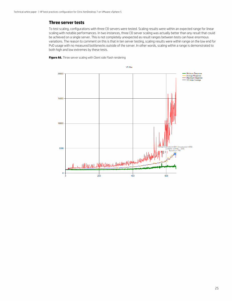
Three server tests
To test scaling, configurations with three (3) servers were tested. Scaling results were within an expected range for linear scaling with notable performances. In two instances, three (3) server scaling was actually better than any result that could be achieved on a single server. This is not completely unexpected as result ranges between tests can have enormous variations. The reason to comment on this is that in ten server testing, scaling results were within range on the low end for PvD usage with no measured bottlenecks outside of the server. In other words, scaling within a range is demonstrated to both high and low extremes by these tests.
Figure A6. Three server scaling with Client side Flash rendering
Technical white paper | HP best practices configuration for Citrix XenDesktop 7 on VMware vSphere 5
26
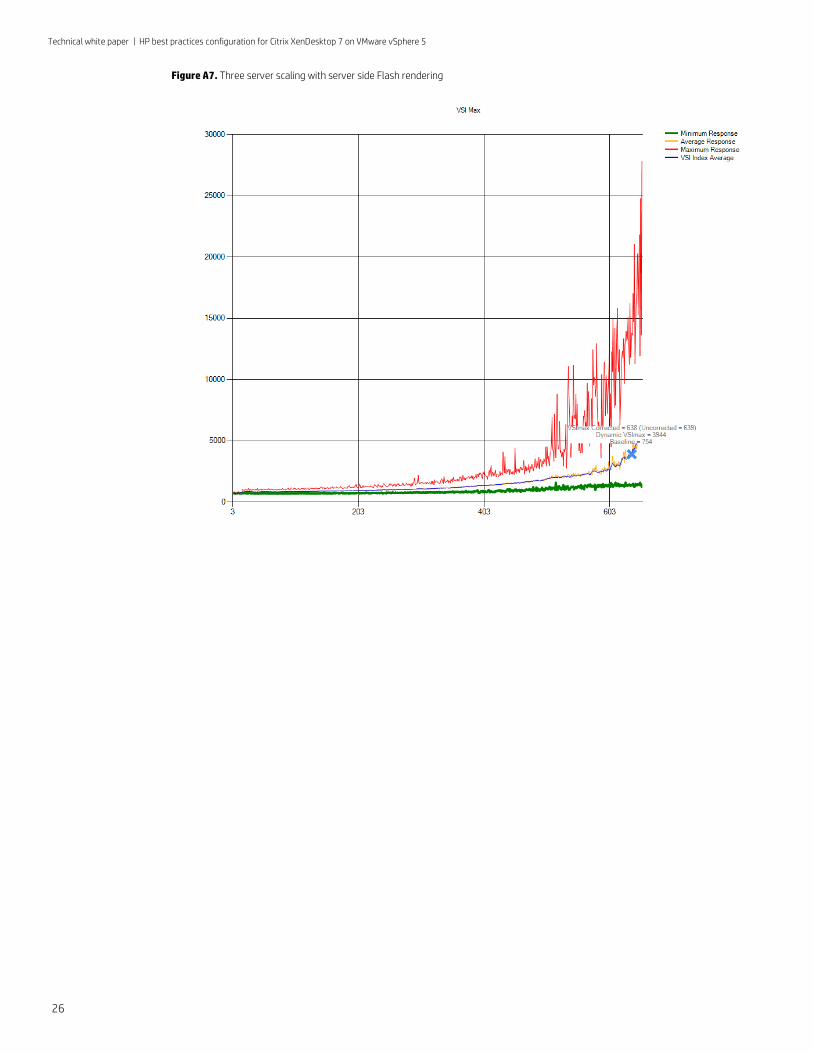
Figure A7. Three server scaling with server side Flash rendering
Technical white paper | HP best practices configuration for Citrix XenDesktop 7 on VMware vSphere 5
27
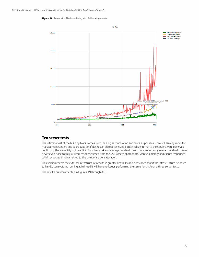
Figure A8. Server side Flash rendering with PvD scaling results
Ten server tests
The ultimate test of the building block comes from utilizing as much of an enclosure as possible while still leaving room for management servers and spare capacity if desired. In all test cases, no bottlenecks external to the servers were observed confirming the scalability of the entire block. Network and storage bandwidth and more importantly overall bandwidth were never even close to fully utilized, response times from the SAN (where appropriate) were exemplary and clients responded within expected timeframes up to the point of server saturation.
This section covers the external infrastructure results in greater depth. It can be assumed that if the infrastructure is shown to handle ten systems running at full load it will have no issues performing the same for single and three server tests.
The results are documented in Figures A9 through A16.
Technical white paper | HP best practices configuration for Citrix XenDesktop 7 on VMware vSphere 5
28
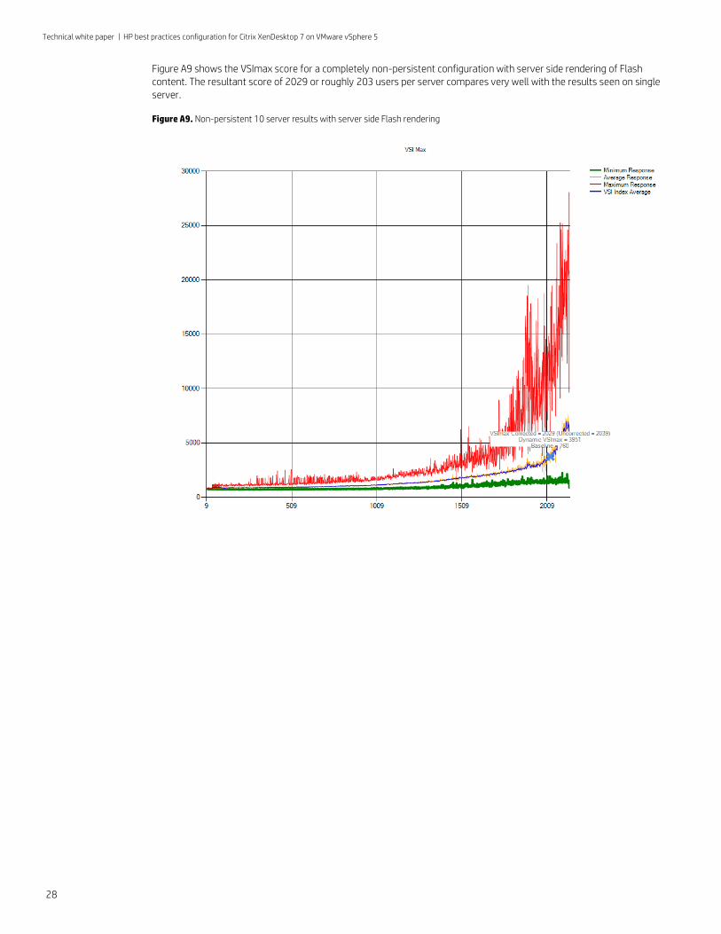
Figure A9 shows the VSImax score for a completely non-persistent configuration with server side rendering of Flash content. The resultant score of 2029 or roughly 203 users per server compares very well with the results seen on single server.
Figure A9. Non-persistent 10 server results with server side Flash rendering
Technical white paper | HP best practices configuration for Citrix XenDesktop 7 on VMware vSphere 5
29
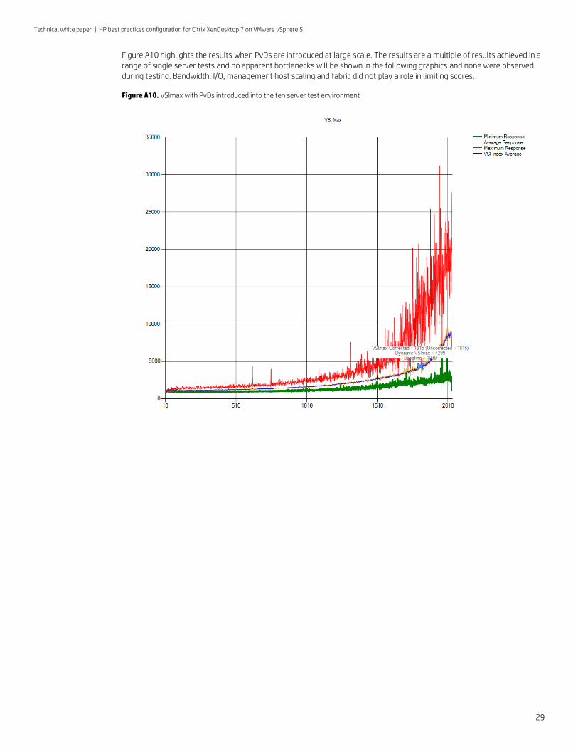
Figure A10 highlights the results when PvDs are introduced at large scale. The results are a multiple of results achieved in a range of single server tests and no apparent bottlenecks will be shown in the following graphics and none were observed during testing. Bandwidth, I/O, management host scaling and fabric did not play a role in limiting scores.
Figure A10. VSImax with PvDs introduced into the ten server test environment
Technical white paper | HP best practices configuration for Citrix XenDesktop 7 on VMware vSphere 5
30
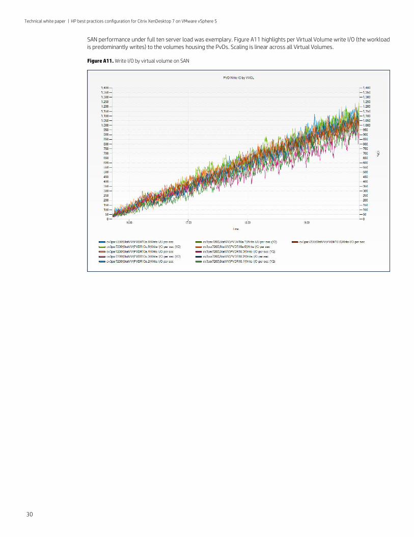
SAN performance under full ten server load was exemplary. Figure A11 highlights per Virtual Volume write I/O (the workload is predominantly writes) to the volumes housing the PvDs. Scaling is linear across all Virtual Volumes.
Figure A11. Write I/O by virtual volume on SAN
Technical white paper | HP best practices configuration for Citrix XenDesktop 7 on VMware vSphere 5
31
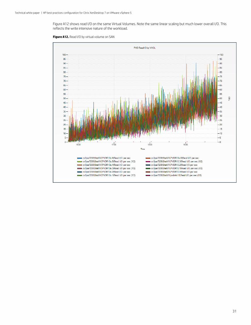
Figure A12 shows read I/O on the same Virtual Volumes. Note the same linear scaling but much lower overall I/O. This reflects the write intensive nature of the workload.
Figure A12. Read I/O by virtual volume on SAN
Technical white paper | HP best practices configuration for Citrix XenDesktop 7 on VMware vSphere 5
32
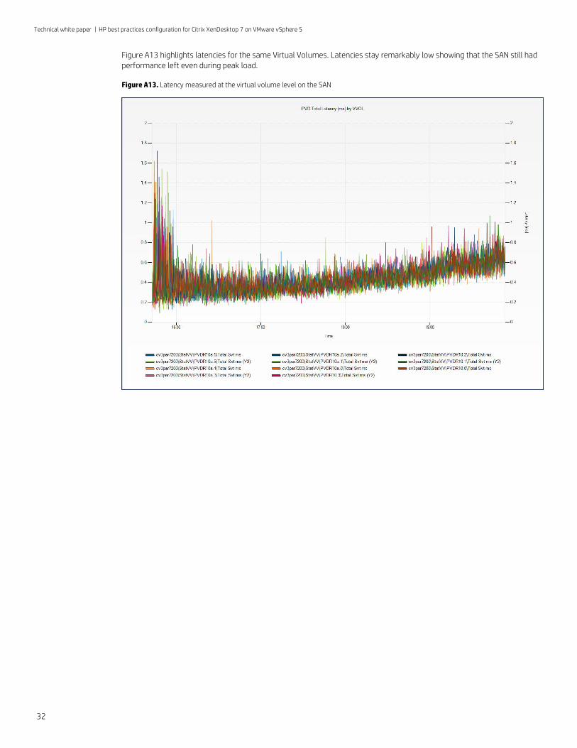
Figure A13 highlights latencies for the same Virtual Volumes. Latencies stay remarkably low showing that the SAN still had performance left even during peak load.
Figure A13. Latency measured at the virtual volume level on the SAN
Technical white paper | HP best practices configuration for Citrix XenDesktop 7 on VMware vSphere 5
33
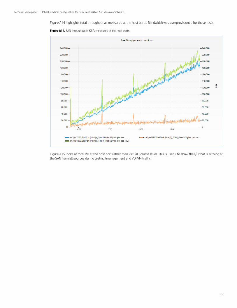
Figure A14 highlights total throughput as measured at the host ports. Bandwidth was overprovisioned for these tests.
Figure A14. SAN throughput in KB/s measured at the host ports
Figure A15 looks at total I/O at the host port rather than Virtual Volume level. This is useful to show the I/O that is arriving at the SAN from all sources during testing (management and VDI VM traffic).
Technical white paper | HP best practices configuration for Citrix XenDesktop 7 on VMware vSphere 5
34
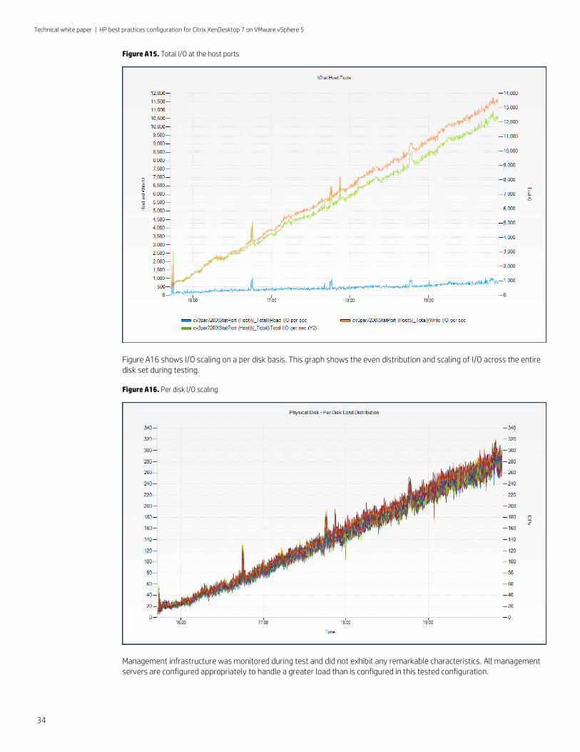
Figure A15. Total I/O at the host ports
Figure A16 shows I/O scaling on a per disk basis. This graph shows the even distribution and scaling of I/O across the entire disk set during testing.
Figure A16. Per disk I/O scaling
Management infrastructure was monitored during test and did not exhibit any remarkable characteristics. All management servers are configured appropriately to handle a greater load than is configured in this tested configuration.
Technical white paper | HP best practices configuration for Citrix XenDesktop 7 on VMware vSphere 5
For more information
For more info on HP and Client Virtualization visit, hp.com/go/cv
For more information on Citrix visit, citrix.com
Why HP 3PAR StoreServ Storage for Client Virtualization and Best Practices, http://www8.hp.com/h20195/v2/GetDocument.aspx?docname=4AA4-6479ENW
HP Networking Converged Infrastructure Reference Architecture, http://h17007.www1.hp.com/us/en/converged-infrastructure/ci-ra.aspx
It is highly recommended that you visit the following sites to understand the management of Citrix PvDs.
Managing PvDs, http://support.citrix.com/proddocs/topic/xendesktop-7/cds-manage-personal-vdisks.html
PvD Best Practices, http://support.citrix.com/proddocs/topic/personal-vdisk-7x/c_1-personal-vdisk-best-practices.html
HP Virtual Connect product page and documentation links, hp.com/go/virtualconnect
HP 3PAR StoreServ 7000, hp.com/go/storeserv7000
HP BladeSystem, hp.com/go/bladesystem
HP StoreEasy Storage, hp.com/go/storeeasy
To help us improve our documents, please provide feedback at hp.com/solutions/feedback.
Sign up for updates
hp.com/go/getupdated
© Copyright 2013 Hewlett-Packard Development Company, L.P. The information contained herein is subject to change without notice. The only warranties for
HP products and services are set forth in the express warranty statements accompanying such products and services. Nothing herein should be construed as
constituting an additional warranty. HP shall not be liable for technical or editorial errors or omissions contained herein.
Microsoft, Windows, Windows 7, and Windows Vista are U.S. registered trademarks of Microsoft Corporation. Intel and Xeon are trademarks of Intel
Corporation in the U.S. and other countries. Adobe is a trademark of Adobe Systems Incorporated.
4AA4-9489ENW, November 2013, Rev. 2