Embed Size (px)
Citation preview
1
How to measure on SOL calibration kits
and how to design your own SOL calibration kit for the VNWA
In the following will be described some measurement trick for the VNWA to better evaluate and
understand the aspect of Short Open and Load calibration standard.
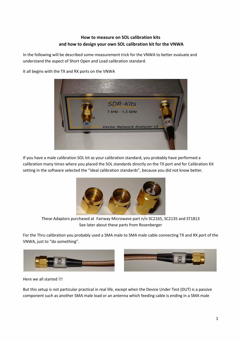
It all begins with the TX and RX ports on the VNWA
If you have a male calibration SOL kit as your calibration standard, you probably have performed a
calibration many times where you placed the SOL standards directly on the TX port and for Calibration Kit
setting in the software selected the “ideal calibration standards”, because you did not know better.
These Adaptors purchased at Fairway Microwave part n/o SC2165, SC2135 and ST1813
See later about these parts from Rosenberger
For the Thru calibration you probably used a SMA male to SMA male cable connecting TX and RX port of the
VNWA, just to “do something”.
Here we all started !!!
But this setup is not particular practical in real life, except when the Device Under Test (DUT) is a passive
component such as another SMA male load or an antenna which feeding cable is ending in a SMA male
2
connector. The Thru calibration is in fact useless as a DUT (e.g. a filter) should be inserted in the middle of
the test cable.
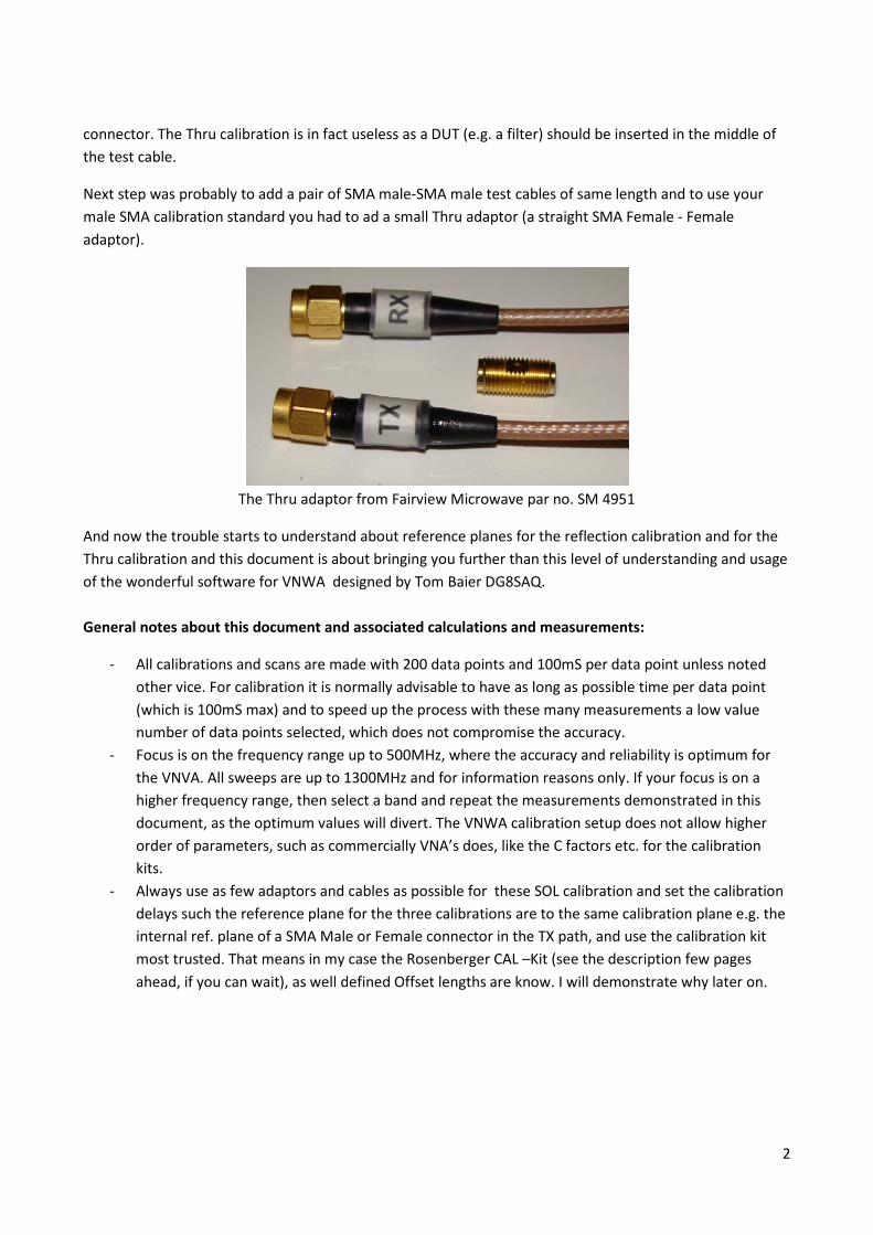
Next step was probably to add a pair of SMA male-SMA male test cables of same length and to use your
male SMA calibration standard you had to ad a small Thru adaptor (a straight SMA Female - Female
adaptor).
The Thru adaptor from Fairview Microwave par no. SM 4951
And now the trouble starts to understand about reference planes for the reflection calibration and for the
Thru calibration and this document is about bringing you further than this level of understanding and usage
of the wonderful software for VNWA designed by Tom Baier DG8SAQ.
General notes about this document and associated calculations and measurements:
- All calibrations and scans are made with 200 data points and 100mS per data point unless noted
other vice. For calibration it is normally advisable to have as long as possible time per data point
(which is 100mS max) and to speed up the process with these many measurements a low value
number of data points selected, which does not compromise the accuracy.
- Focus is on the frequency range up to 500MHz, where the accuracy and reliability is optimum for
the VNVA. All sweeps are up to 1300MHz and for information reasons only. If your focus is on a
higher frequency range, then select a band and repeat the measurements demonstrated in this
document, as the optimum values will divert. The VNWA calibration setup does not allow higher
order of parameters, such as commercially VNA’s does, like the C factors etc. for the calibration
kits.
- Always use as few adaptors and cables as possible for these SOL calibration and set the calibration
delays such the reference plane for the three calibrations are to the same calibration plane e.g. the
internal ref. plane of a SMA Male or Female connector in the TX path, and use the calibration kit
most trusted. That means in my case the Rosenberger CAL –Kit (see the description few pages
ahead, if you can wait), as well defined Offset lengths are know. I will demonstrate why later on.
3
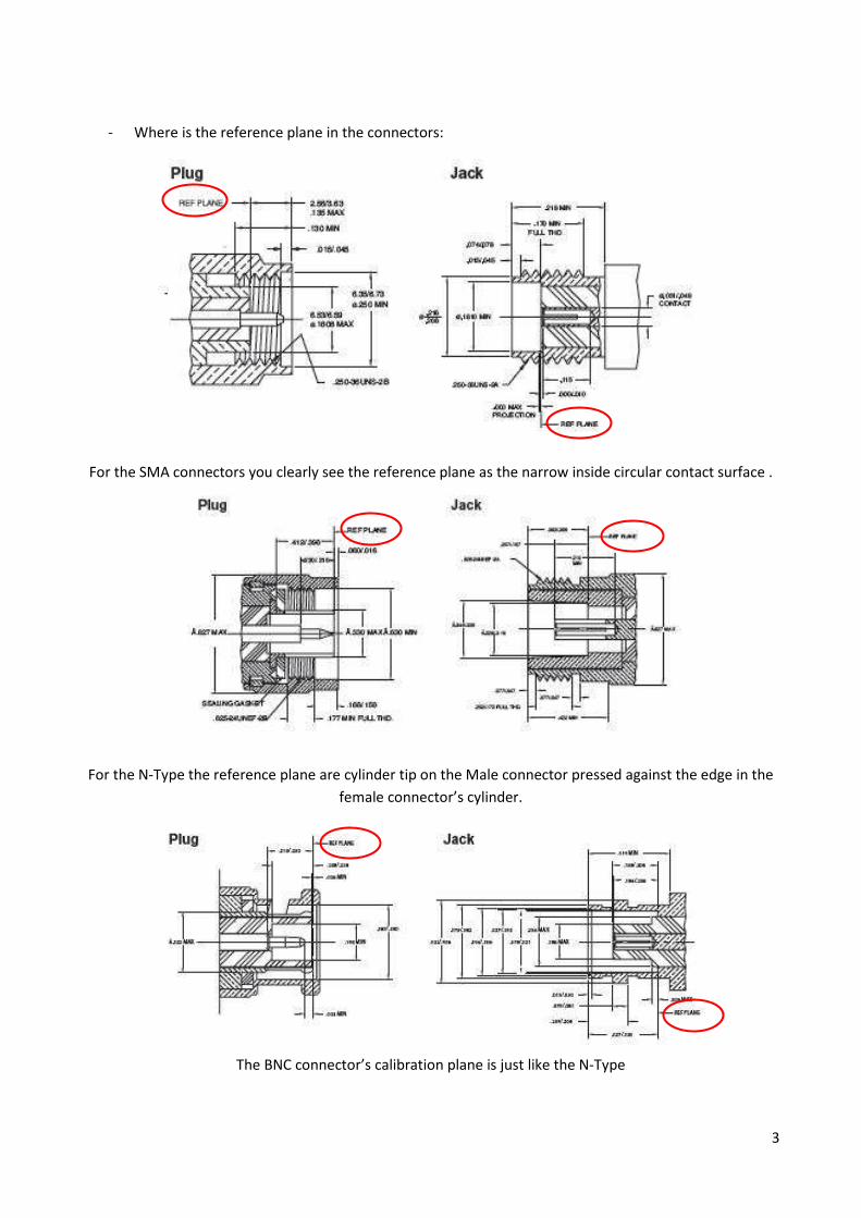
- Where is the reference plane in the connectors:
For the SMA connectors you clearly see the reference plane as the narrow inside circular contact surface .
For the N-Type the reference plane are cylinder tip on the Male connector pressed against the edge in the
female connector’s cylinder.
The BNC connector’s calibration plane is just like the N-Type
4
In the following we will see how to calibrate the VNWA to have the calibration reference plane identical to
the internal reference plane of the SMA Male connector, at the end of the test cable, which can be quite
practical when measuring on DUT’s like a 450MHz filter in metal case with flanged connectors mounted on
the case. We will also see how we move the reference plane to the inside of such a connector, alternative
calibrate the VMWA to measure on the inside of said connector.
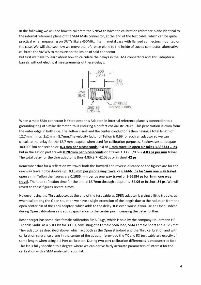
But first we have to learn about how to calculate the delays in the SMA connectors and Thru adaptors/
barrels without electrical measurements of these delays.
When a male SMA connector is fitted onto this Adaptor its internal reference plane is connection to a
grounding ring of similar diameter, thus ensuring a perfect coaxial structure. This penetration is 2mm from
the outer edge in both side. The Teflon insert and the center conductor is then having a total length of
12.7mm minus 2x2mm = 8.7mm.The velocity factor of Teflon is 0.69 for such an adaptor so we can
calculate the delay for the 12,7 mm adaptor when used for calibration purposes. Radiowaves propagate
300.000 km per second or 0,3 mm per picoseconds (ps) or 1 mm travel in open air takes 3.333333 … ps,
but in the Teflon part travels 0.207mm per picoseconds or it takes 3.33333/0.69= 4.83 ps per mm travel.
The total delay for the thru adaptor is thus 4.83x8.7=42.03ps or in short 42 ps.
Remember that for a reflection we travel both the forward and reverse distance so the figures are for the
one way travel to be double up. 0,15 mm per ps one way travel or 6.6666…ps for 1mm one way travel
open air. In Teflon the figures are 0,1035 mm per ps one way travel or 9.66184 ps for 1mm one way
travel. The total reflection time for the entire 12.7mm through adaptor is 84.06 or in short 84 ps. We will
revert to these figures several times.
However using the Thru adaptor, at the end of the test cable as OPEN adaptor is giving a little trouble, as
when calibrating the Open situation we have a slight extension of the length due to the radiation from the
open center pin of the Thru adaptor, which adds to the delay. It is even worse if you use an Open Endcap
during Open calibration as it adds capacitance to the center pin, increasing the delay further.
Rosenberger has some nice female calibration SMA Plugs, which is sold by the company Heuermann HF-
Technik GmbH as a SOLT kit for 30 EU, consisting of a Female SMA load, SMA Female Short and a 12.7mm
Thru adaptor as described above, which act both as the Open standard and the Thru calibration and with
calibration reference plane in the center of the adaptor (provided the TX and RX test cable are exactly of
same length when using a 1 Port calibration. During two port calibration differences is encountered for).
This kit is fully specified to a degree where we can derive fairly accurate parameters of interest for the
calibration with a SMA male calibration kit.
5
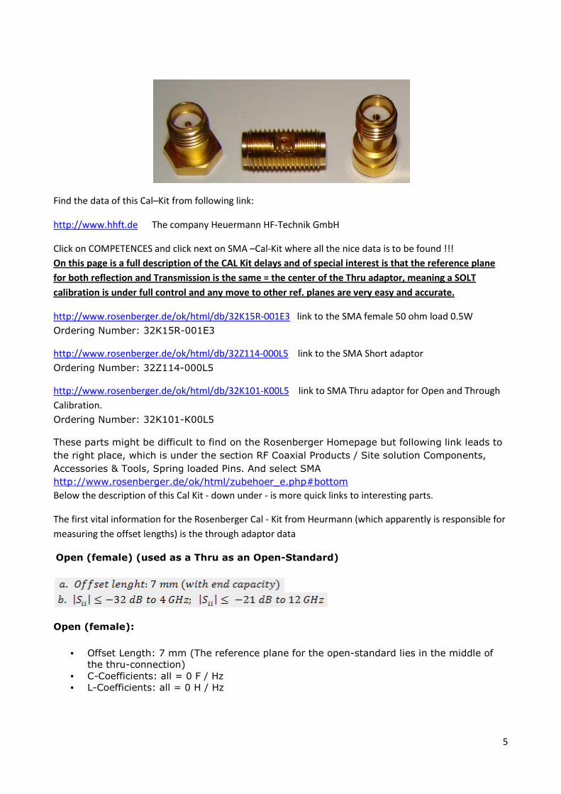
Find the data of this Cal–Kit from following link:
http://www.hhft.de The company Heuermann HF-Technik GmbH
Click on COMPETENCES and click next on SMA –Cal-Kit where all the nice data is to be found !!!
On this page is a full description of the CAL Kit delays and of special interest is that the reference plane
for both reflection and Transmission is the same = the center of the Thru adaptor, meaning a SOLT
calibration is under full control and any move to other ref. planes are very easy and accurate.
http://www.rosenberger.de/ok/html/db/32K15R-001E3 link to the SMA female 50 ohm load 0.5W
Ordering Number: 32K15R-001E3
http://www.rosenberger.de/ok/html/db/32Z114-000L5 link to the SMA Short adaptor
Ordering Number: 32Z114-000L5
http://www.rosenberger.de/ok/html/db/32K101-K00L5 link to SMA Thru adaptor for Open and Through
Calibration.
Ordering Number: 32K101-K00L5
These parts might be difficult to find on the Rosenberger Homepage but following link leads to
the right place, which is under the section RF Coaxial Products / Site solution Components,
Accessories & Tools, Spring loaded Pins. And select SMA
http://www.rosenberger.de/ok/html/zubehoer_e.php#bottom
Below the description of this Cal Kit - down under - is more quick links to interesting parts.
The first vital information for the Rosenberger Cal - Kit from Heurmann (which apparently is responsible for
measuring the offset lengths) is the through adaptor data
Open (female) (used as a Thru as an Open-Standard)
Open (female):
• Offset Length: 7 mm (The reference plane for the open-standard lies in the middle of
the thru-connection)
• C-Coefficients: all = 0 F / Hz
• L-Coefficients: all = 0 H / Hz
6
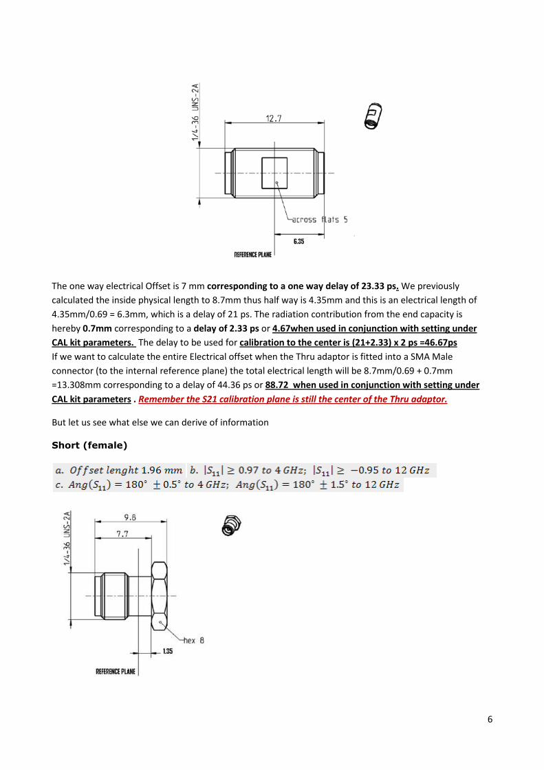
The one way electrical Offset is 7 mm corresponding to a one way delay of 23.33 ps. We previously
calculated the inside physical length to 8.7mm thus half way is 4.35mm and this is an electrical length of
4.35mm/0.69 = 6.3mm, which is a delay of 21 ps. The radiation contribution from the end capacity is
hereby 0.7mm corresponding to a delay of 2.33 ps or 4.67when used in conjunction with setting under
CAL kit parameters. The delay to be used for calibration to the center is (21+2.33) x 2 ps =46.67ps
If we want to calculate the entire Electrical offset when the Thru adaptor is fitted into a SMA Male
connector (to the internal reference plane) the total electrical length will be 8.7mm/0.69 + 0.7mm
=13.308mm corresponding to a delay of 44.36 ps or 88.72 when used in conjunction with setting under
CAL kit parameters . Remember the S21 calibration plane is still the center of the Thru adaptor.
But let us see what else we can derive of information
Short (female)
7
The Electrical Offset length is 1.96mm - corresponding to 6.5333..ps or 13.07ps ps when used in
conjunction with setting under CAL kit parameters - and the physical length is 1.96 mm X 0.69 = 1.35mm,
just as the distance to the Reference Plane is shown on the drawing (proof of the assumed velocity factor
for the Teflon !). If we want to calculate the offset to the Reference plane of the mating SMA male
connector then we just subtract 2mm from the 7.7 mm on the drawing and divide by 0.69 to find the
electrical length = 8.26 mm corresponding to 27.54 ps or 55.07 ps when used in conjunction with setting
under CAL kit parameters. Remember the S21 calibration plane is still the center of the Thru adaptor.
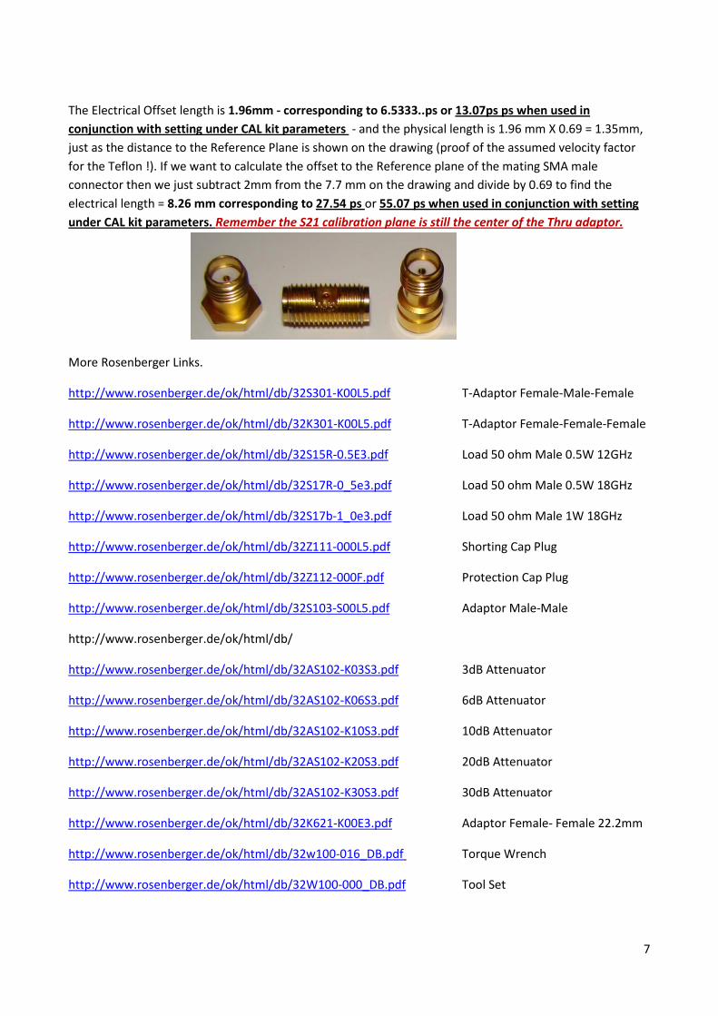
More Rosenberger Links.
http://www.rosenberger.de/ok/html/db/32S301-K00L5.pdf T-Adaptor Female-Male-Female
http://www.rosenberger.de/ok/html/db/32K301-K00L5.pdf T-Adaptor Female-Female-Female
http://www.rosenberger.de/ok/html/db/32S15R-0.5E3.pdf Load 50 ohm Male 0.5W 12GHz
http://www.rosenberger.de/ok/html/db/32S17R-0_5e3.pdf Load 50 ohm Male 0.5W 18GHz
http://www.rosenberger.de/ok/html/db/32S17b-1_0e3.pdf Load 50 ohm Male 1W 18GHz
http://www.rosenberger.de/ok/html/db/32Z111-000L5.pdf Shorting Cap Plug
http://www.rosenberger.de/ok/html/db/32Z112-000F.pdf Protection Cap Plug
http://www.rosenberger.de/ok/html/db/32S103-S00L5.pdf Adaptor Male-Male
http://www.rosenberger.de/ok/html/db/
http://www.rosenberger.de/ok/html/db/32AS102-K03S3.pdf 3dB Attenuator
http://www.rosenberger.de/ok/html/db/32AS102-K06S3.pdf 6dB Attenuator
http://www.rosenberger.de/ok/html/db/32AS102-K10S3.pdf 10dB Attenuator
http://www.rosenberger.de/ok/html/db/32AS102-K20S3.pdf 20dB Attenuator
http://www.rosenberger.de/ok/html/db/32AS102-K30S3.pdf 30dB Attenuator
http://www.rosenberger.de/ok/html/db/32K621-K00E3.pdf Adaptor Female- Female 22.2mm
http://www.rosenberger.de/ok/html/db/32w100-016_DB.pdf Torque Wrench
http://www.rosenberger.de/ok/html/db/32W100-000_DB.pdf Tool Set
8
Some few words about the Calibration LOAD.
You should measure it accurately which must be done by a 4 point Kelvin measurement. Use a series
connection of an 820ohm resistor, 100 ohm 0.1% resistors and the SOL load. Feed the series connection
with an adjustable voltage of 10V and regulate the supply until the voltage across the 100ohm resistor –
and measure directly across the terminals of this resistor – until the voltage is 1 voltage. Now measure the
voltage across the load e.g. 0.504 Volt and the resistor must be 50.4 ohm. Use this value in the settings for
calibration kit
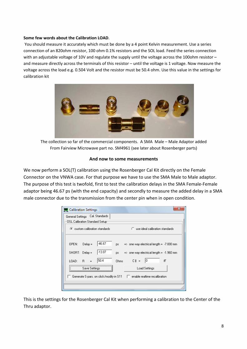
The collection so far of the commercial components. A SMA Male – Male Adaptor added
From Fairview Microwave part no. SM4961 (see later about Rosenberger parts)
And now to some measurements
We now perform a SOL(T) calibration using the Rosenberger Cal Kit directly on the Female
Connector on the VNWA case. For that purpose we have to use the SMA Male to Male adaptor.
The purpose of this test is twofold, first to test the calibration delays in the SMA Female-Female
adaptor being 46.67 ps (with the end capacity) and secondly to measure the added delay in a SMA
male connector due to the transmission from the center pin when in open condition.
This is the settings for the Rosenberger Cal Kit when performing a calibration to the Center of the
Thru adaptor.
9
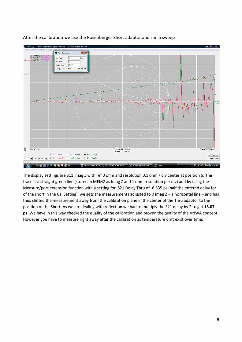
After the calibration we use the Rosenberger Short adaptor and run a sweep
The display settings are S11 Imag Z with ref 0 ohm and resolution 0.1 ohm / div center at position 5. The
trace is a straight green line (stored in MEM2 as Imag Z and 1 ohm resolution per div) and by using the
Measure/port extension function with a setting for S21 Delay Thru of -6.535 ps (half the entered delay for
of the short in the Cal Setting), we gets the measurements adjusted to 0 Imag Z – a horizontal line – and has
thus shifted the measurement away from the calibration plane in the center of the Thru adaptor to the
position of the Short. As we are dealing with reflection we had to multiply the S21 delay by 2 to get 13.07
ps. We have in this way checked the quality of the calibration and proved the quality of the VNWA concept.
However you have to measure right away after the calibration as temperature drift exist over time.
10
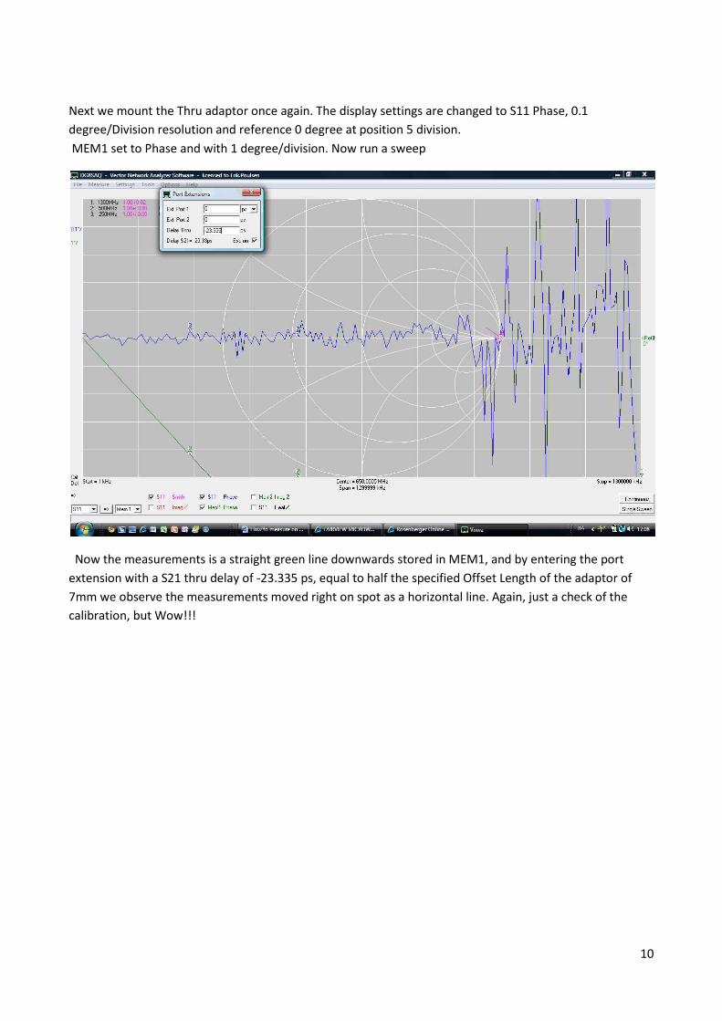
Next we mount the Thru adaptor once again. The display settings are changed to S11 Phase, 0.1
degree/Division resolution and reference 0 degree at position 5 division.
MEM1 set to Phase and with 1 degree/division. Now run a sweep
Now the measurements is a straight green line downwards stored in MEM1, and by entering the port
extension with a S21 thru delay of -23.335 ps, equal to half the specified Offset Length of the adaptor of
7mm we observe the measurements moved right on spot as a horizontal line. Again, just a check of the
calibration, but Wow!!!
11
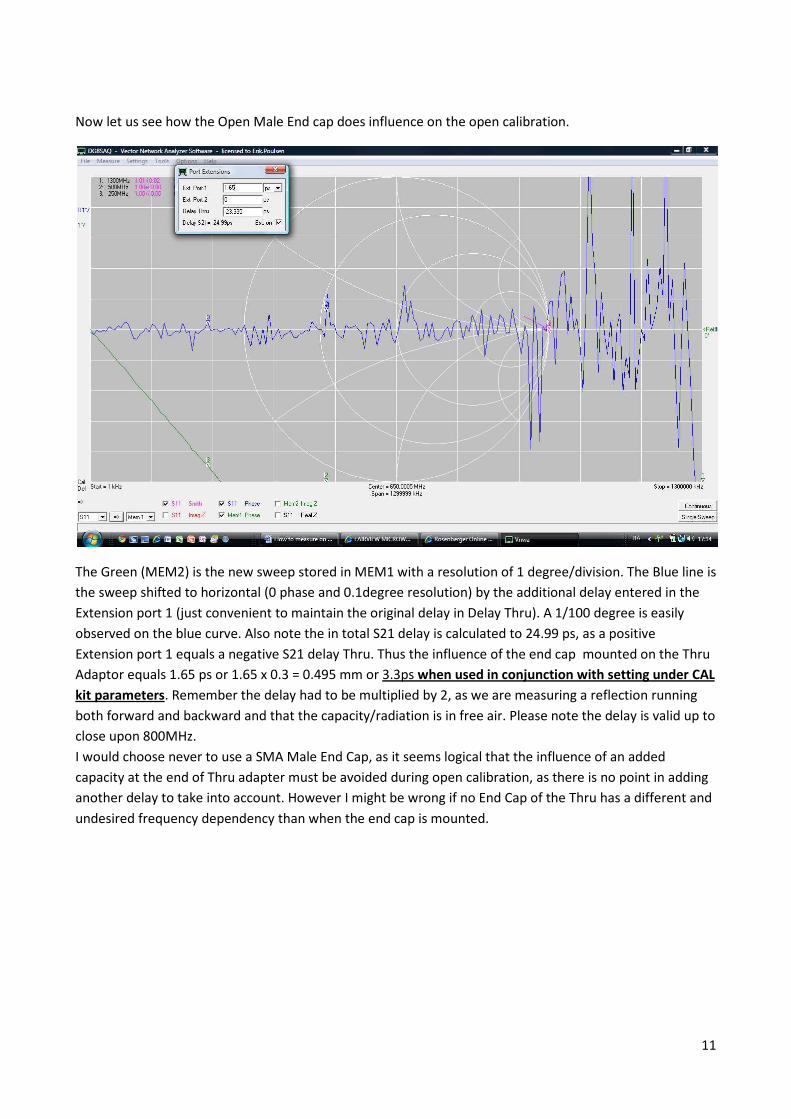
Now let us see how the Open Male End cap does influence on the open calibration.
The Green (MEM2) is the new sweep stored in MEM1 with a resolution of 1 degree/division. The Blue line is
the sweep shifted to horizontal (0 phase and 0.1degree resolution) by the additional delay entered in the
Extension port 1 (just convenient to maintain the original delay in Delay Thru). A 1/100 degree is easily
observed on the blue curve. Also note the in total S21 delay is calculated to 24.99 ps, as a positive
Extension port 1 equals a negative S21 delay Thru. Thus the influence of the end cap mounted on the Thru
Adaptor equals 1.65 ps or 1.65 x 0.3 = 0.495 mm or 3.3ps when used in conjunction with setting under CAL
kit parameters. Remember the delay had to be multiplied by 2, as we are measuring a reflection running
both forward and backward and that the capacity/radiation is in free air. Please note the delay is valid up to
close upon 800MHz.
I would choose never to use a SMA Male End Cap, as it seems logical that the influence of an added
capacity at the end of Thru adapter must be avoided during open calibration, as there is no point in adding
another delay to take into account. However I might be wrong if no End Cap of the Thru has a different and
undesired frequency dependency than when the end cap is mounted.
12
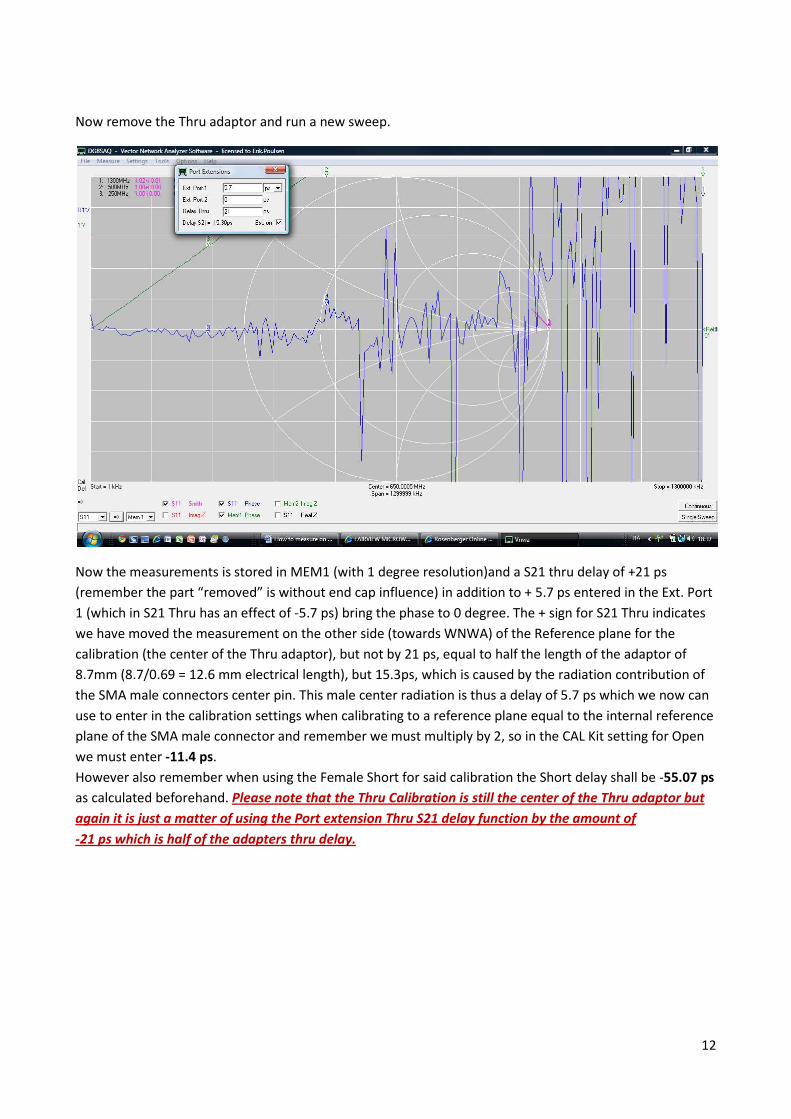
Now remove the Thru adaptor and run a new sweep.
Now the measurements is stored in MEM1 (with 1 degree resolution)and a S21 thru delay of +21 ps
(remember the part “removed” is without end cap influence) in addition to + 5.7 ps entered in the Ext. Port
1 (which in S21 Thru has an effect of -5.7 ps) bring the phase to 0 degree. The + sign for S21 Thru indicates
we have moved the measurement on the other side (towards WNWA) of the Reference plane for the
calibration (the center of the Thru adaptor), but not by 21 ps, equal to half the length of the adaptor of
8.7mm (8.7/0.69 = 12.6 mm electrical length), but 15.3ps, which is caused by the radiation contribution of
the SMA male connectors center pin. This male center radiation is thus a delay of 5.7 ps which we now can
use to enter in the calibration settings when calibrating to a reference plane equal to the internal reference
plane of the SMA male connector and remember we must multiply by 2, so in the CAL Kit setting for Open
we must enter -11.4 ps.
However also remember when using the Female Short for said calibration the Short delay shall be -55.07 ps
as calculated beforehand. Please note that the Thru Calibration is still the center of the Thru adaptor but
again it is just a matter of using the Port extension Thru S21 delay function by the amount of
-21 ps which is half of the adapters thru delay.
13
Summary of all the many tests:
The previous calculations and measurement has been executed to gain understanding of the delays in the
various parts involved for calibration which in its simplicity can be brought to following conclusions.
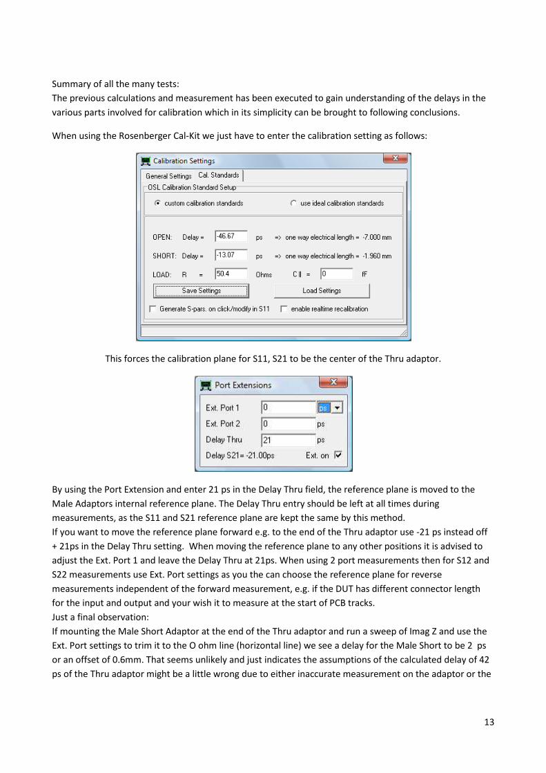
When using the Rosenberger Cal-Kit we just have to enter the calibration setting as follows:
This forces the calibration plane for S11, S21 to be the center of the Thru adaptor.
By using the Port Extension and enter 21 ps in the Delay Thru field, the reference plane is moved to the
Male Adaptors internal reference plane. The Delay Thru entry should be left at all times during
measurements, as the S11 and S21 reference plane are kept the same by this method.
If you want to move the reference plane forward e.g. to the end of the Thru adaptor use -21 ps instead off
+ 21ps in the Delay Thru setting. When moving the reference plane to any other positions it is advised to
adjust the Ext. Port 1 and leave the Delay Thru at 21ps. When using 2 port measurements then for S12 and
S22 measurements use Ext. Port settings as you the can choose the reference plane for reverse
measurements independent of the forward measurement, e.g. if the DUT has different connector length
for the input and output and your wish it to measure at the start of PCB tracks.
Just a final observation:
If mounting the Male Short Adaptor at the end of the Thru adaptor and run a sweep of Imag Z and use the
Ext. Port settings to trim it to the O ohm line (horizontal line) we see a delay for the Male Short to be 2 ps
or an offset of 0.6mm. That seems unlikely and just indicates the assumptions of the calculated delay of 42
ps of the Thru adaptor might be a little wrong due to either inaccurate measurement on the adaptor or the
14
dielectric coefficient is slightly different. However we are dealing with errors which are without any
practical impact on measurements in the real life.
That completes all what is needed to know to go ahead and calibrate in any fashion moving the reference
plane to wherever you like, and using any type of SOL(T) kit provided you trust the information given on
the open end capacity contribution for the Thru of 0.7mm corresponding to a delay of 2.33 ps or 4.67 ps
when used in conjunction with setting under CAL kit parameters giving a total delay for the entire length
of 88.72 ps when used in conjunction with setting under CAL kit parameters, and for the open
radiation/capacity contribution of the center pin of a Male SMA connector a delay of 5.7ps or 11.4 ps
when used in conjunction with setting under CAL kit parameters. (repeated test did show a delay of
5.4ps)
15
What about test leads ?
As the Thru calibration for one port measurements, always has its reference plane at the end of the Thru
adaptor (provided nothing is entered for the Open and Short in the calibration settings, and subsequent
find the additional cable length between the end of the Thru adaptor and the RX port during the Thru
calibration there is taken care of differences between the length of the TX and RX test cable length.
However for one port calibration “only” 6 term calibration takes place and for perfect measurements - at
least above 900 MHz making a T-Check test with different cable length) it is advisable that the TX and RX
cables to be of identical electrical length.
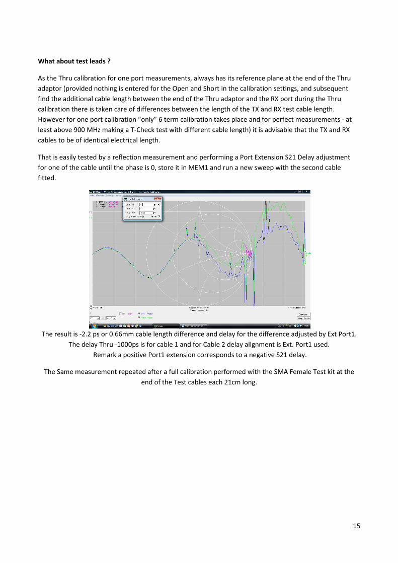
That is easily tested by a reflection measurement and performing a Port Extension S21 Delay adjustment
for one of the cable until the phase is 0, store it in MEM1 and run a new sweep with the second cable
fitted.
The result is -2.2 ps or 0.66mm cable length difference and delay for the difference adjusted by Ext Port1.
The delay Thru -1000ps is for cable 1 and for Cable 2 delay alignment is Ext. Port1 used.
Remark a positive Port1 extension corresponds to a negative S21 delay.
The Same measurement repeated after a full calibration performed with the SMA Female Test kit at the
end of the Test cables each 21cm long.
16
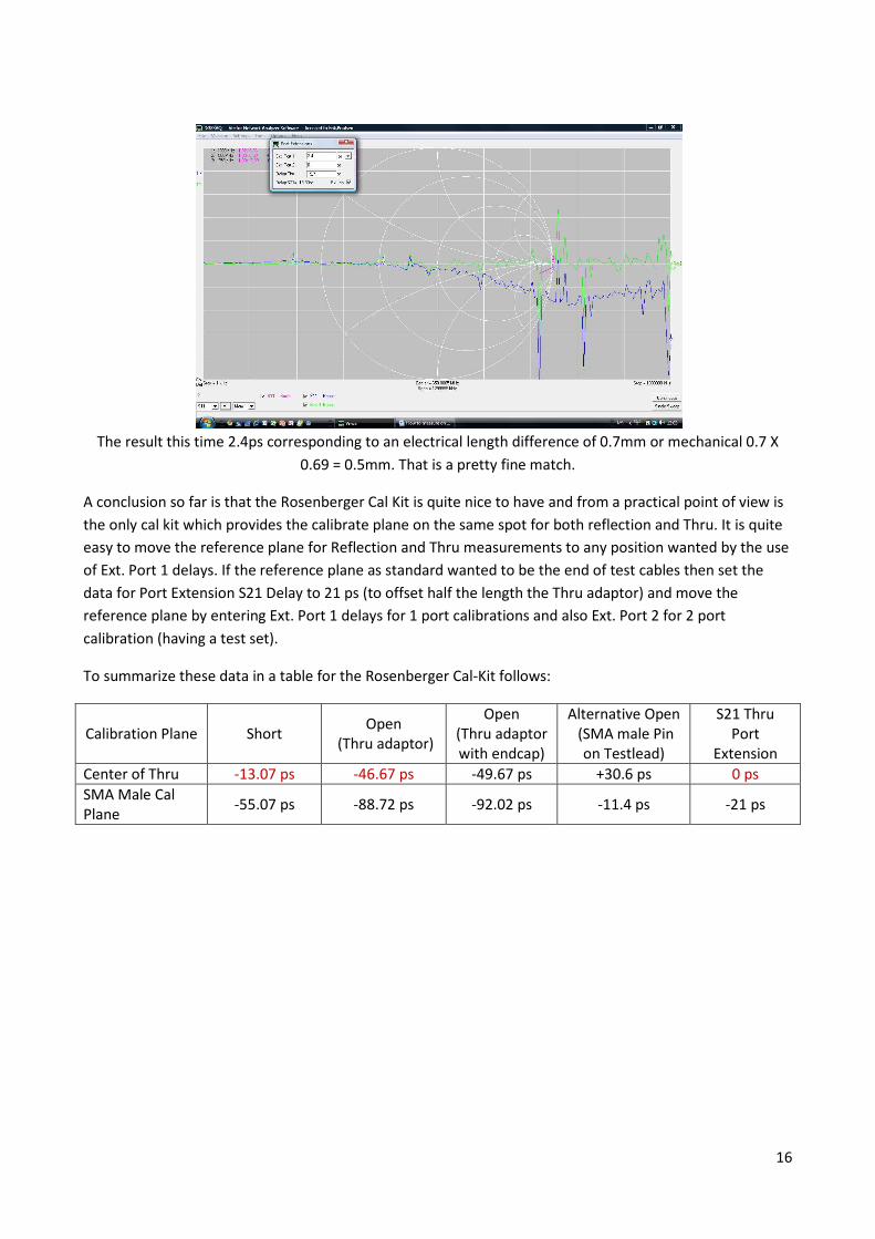
The result this time 2.4ps corresponding to an electrical length difference of 0.7mm or mechanical 0.7 X
0.69 = 0.5mm. That is a pretty fine match.
A conclusion so far is that the Rosenberger Cal Kit is quite nice to have and from a practical point of view is
the only cal kit which provides the calibrate plane on the same spot for both reflection and Thru. It is quite
easy to move the reference plane for Reflection and Thru measurements to any position wanted by the use
of Ext. Port 1 delays. If the reference plane as standard wanted to be the end of test cables then set the
data for Port Extension S21 Delay to 21 ps (to offset half the length the Thru adaptor) and move the
reference plane by entering Ext. Port 1 delays for 1 port calibrations and also Ext. Port 2 for 2 port
calibration (having a test set).
To summarize these data in a table for the Rosenberger Cal-Kit follows:
Calibration Plane Short Open
(Thru adaptor)
Open
(Thru adaptor
with endcap)
Alternative Open
(SMA male Pin
on Testlead)
S21 Thru
Port
Extension
Center of Thru -13.07 ps -46.67 ps -49.67 ps +30.6 ps 0 ps
SMA Male Cal
Plane -55.07 ps -88.72 ps -92.02 ps -11.4 ps -21 ps
17
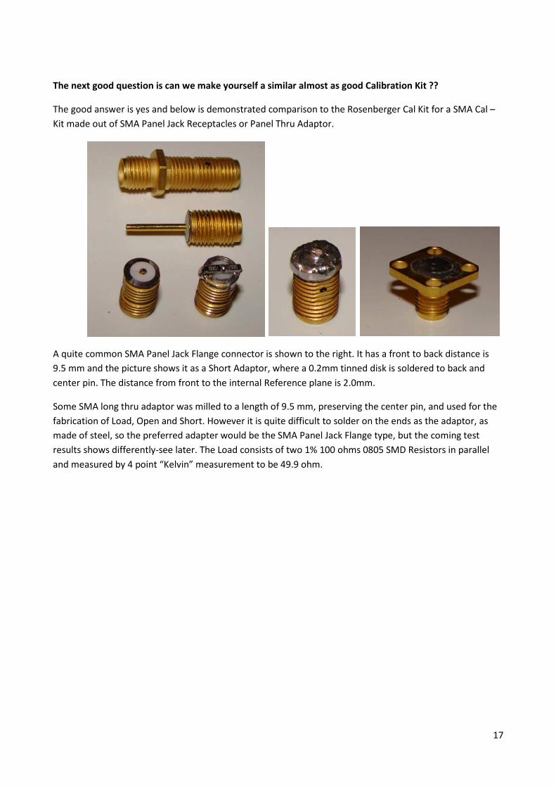
The next good question is can we make yourself a similar almost as good Calibration Kit ??
The good answer is yes and below is demonstrated comparison to the Rosenberger Cal Kit for a SMA Cal –
Kit made out of SMA Panel Jack Receptacles or Panel Thru Adaptor.
A quite common SMA Panel Jack Flange connector is shown to the right. It has a front to back distance is
9.5 mm and the picture shows it as a Short Adaptor, where a 0.2mm tinned disk is soldered to back and
center pin. The distance from front to the internal Reference plane is 2.0mm.
Some SMA long thru adaptor was milled to a length of 9.5 mm, preserving the center pin, and used for the
fabrication of Load, Open and Short. However it is quite difficult to solder on the ends as the adaptor, as
made of steel, so the preferred adapter would be the SMA Panel Jack Flange type, but the coming test
results shows differently-see later. The Load consists of two 1% 100 ohms 0805 SMD Resistors in parallel
and measured by 4 point “Kelvin” measurement to be 49.9 ohm.
18
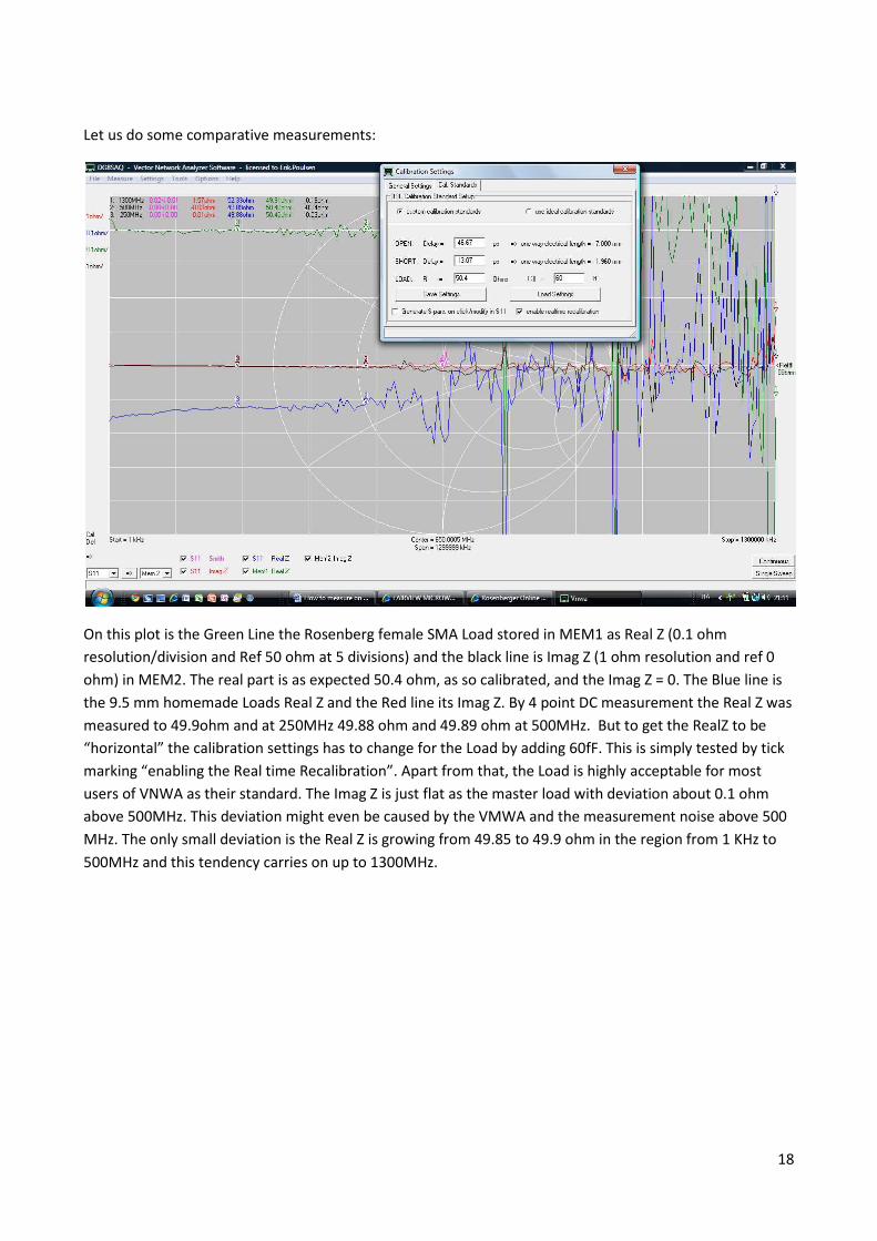
Let us do some comparative measurements:
On this plot is the Green Line the Rosenberg female SMA Load stored in MEM1 as Real Z (0.1 ohm
resolution/division and Ref 50 ohm at 5 divisions) and the black line is Imag Z (1 ohm resolution and ref 0
ohm) in MEM2. The real part is as expected 50.4 ohm, as so calibrated, and the Imag Z = 0. The Blue line is
the 9.5 mm homemade Loads Real Z and the Red line its Imag Z. By 4 point DC measurement the Real Z was
measured to 49.9ohm and at 250MHz 49.88 ohm and 49.89 ohm at 500MHz. But to get the RealZ to be
“horizontal” the calibration settings has to change for the Load by adding 60fF. This is simply tested by tick
marking “enabling the Real time Recalibration”. Apart from that, the Load is highly acceptable for most
users of VNWA as their standard. The Imag Z is just flat as the master load with deviation about 0.1 ohm
above 500MHz. This deviation might even be caused by the VMWA and the measurement noise above 500
MHz. The only small deviation is the Real Z is growing from 49.85 to 49.9 ohm in the region from 1 KHz to
500MHz and this tendency carries on up to 1300MHz.
19
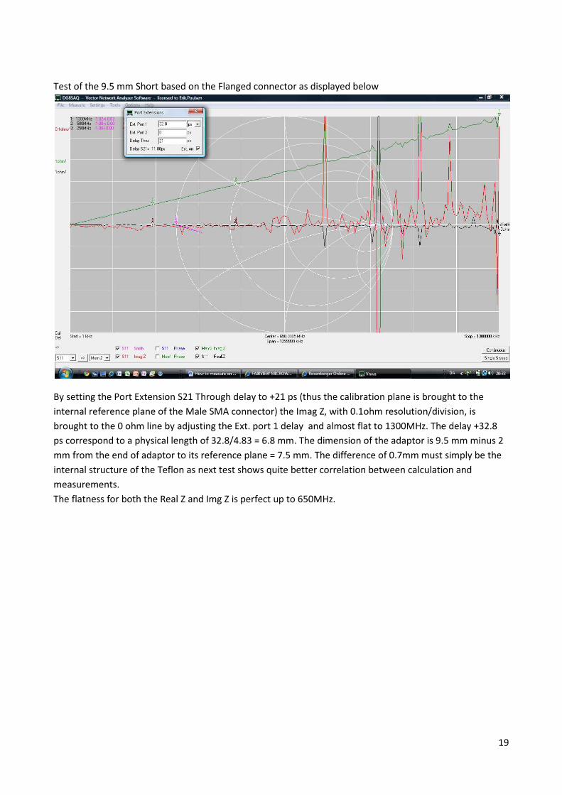
Test of the 9.5 mm Short based on the Flanged connector as displayed below
By setting the Port Extension S21 Through delay to +21 ps (thus the calibration plane is brought to the
internal reference plane of the Male SMA connector) the Imag Z, with 0.1ohm resolution/division, is
brought to the 0 ohm line by adjusting the Ext. port 1 delay and almost flat to 1300MHz. The delay +32.8
ps correspond to a physical length of 32.8/4.83 = 6.8 mm. The dimension of the adaptor is 9.5 mm minus 2
mm from the end of adaptor to its reference plane = 7.5 mm. The difference of 0.7mm must simply be the
internal structure of the Teflon as next test shows quite better correlation between calculation and
measurements.
The flatness for both the Real Z and Img Z is perfect up to 650MHz.
20
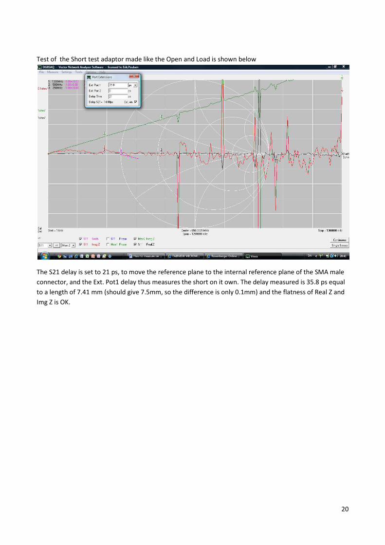
Test of the Short test adaptor made like the Open and Load is shown below
The S21 delay is set to 21 ps, to move the reference plane to the internal reference plane of the SMA male
connector, and the Ext. Pot1 delay thus measures the short on it own. The delay measured is 35.8 ps equal
to a length of 7.41 mm (should give 7.5mm, so the difference is only 0.1mm) and the flatness of Real Z and
Img Z is OK.
21
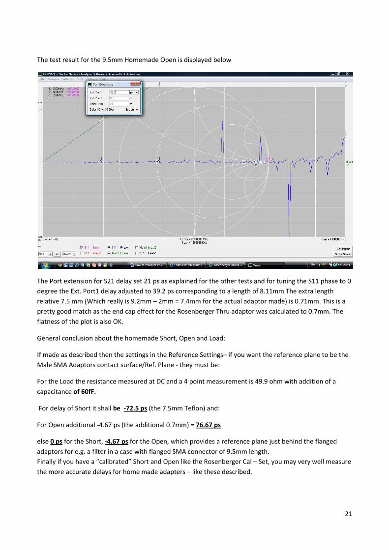
The test result for the 9.5mm Homemade Open is displayed below
The Port extension for S21 delay set 21 ps as explained for the other tests and for tuning the S11 phase to 0
degree the Ext. Port1 delay adjusted to 39.2 ps corresponding to a length of 8.11mm The extra length
relative 7.5 mm (Which really is 9.2mm – 2mm = 7.4mm for the actual adaptor made) is 0.71mm. This is a
pretty good match as the end cap effect for the Rosenberger Thru adaptor was calculated to 0.7mm. The
flatness of the plot is also OK.
General conclusion about the homemade Short, Open and Load:
If made as described then the settings in the Reference Settings– if you want the reference plane to be the
Male SMA Adaptors contact surface/Ref. Plane - they must be:
For the Load the resistance measured at DC and a 4 point measurement is 49.9 ohm with addition of a
capacitance of 60fF.
For delay of Short it shall be -72.5 ps (the 7.5mm Teflon) and:
For Open additional -4.67 ps (the additional 0.7mm) = 76.67 ps
else 0 ps for the Short, -4.67 ps for the Open, which provides a reference plane just behind the flanged
adaptors for e.g. a filter in a case with flanged SMA connector of 9.5mm length.
Finally if you have a “calibrated” Short and Open like the Rosenberger Cal – Set, you may very well measure
the more accurate delays for home made adapters – like these described.
22
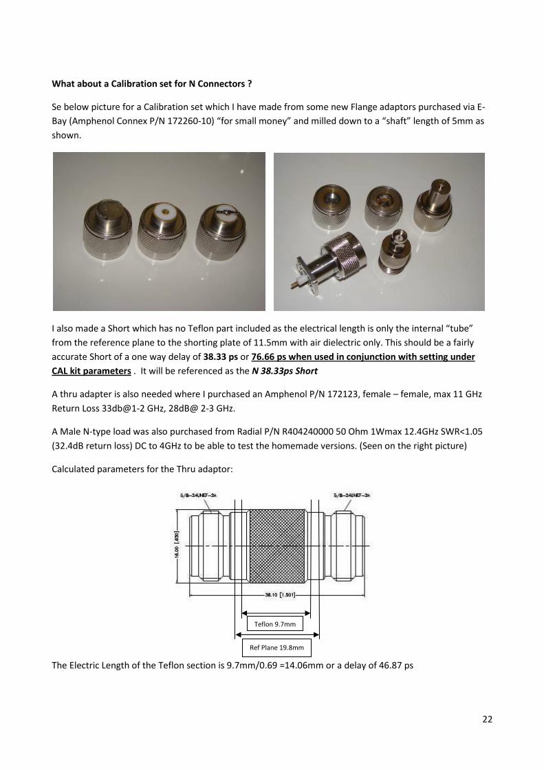
What about a Calibration set for N Connectors ?
Se below picture for a Calibration set which I have made from some new Flange adaptors purchased via E-
Bay (Amphenol Connex P/N 172260-10) “for small money” and milled down to a “shaft” length of 5mm as
shown.
I also made a Short which has no Teflon part included as the electrical length is only the internal “tube”
from the reference plane to the shorting plate of 11.5mm with air dielectric only. This should be a fairly
accurate Short of a one way delay of 38.33 ps or 76.66 ps when used in conjunction with setting under
CAL kit parameters . It will be referenced as the N 38.33ps Short
A thru adapter is also needed where I purchased an Amphenol P/N 172123, female – female, max 11 GHz
Return Loss 33db@1-2 GHz, 28dB@ 2-3 GHz.
A Male N-type load was also purchased from Radial P/N R404240000 50 Ohm 1Wmax 12.4GHz SWR<1.05
(32.4dB return loss) DC to 4GHz to be able to test the homemade versions. (Seen on the right picture)
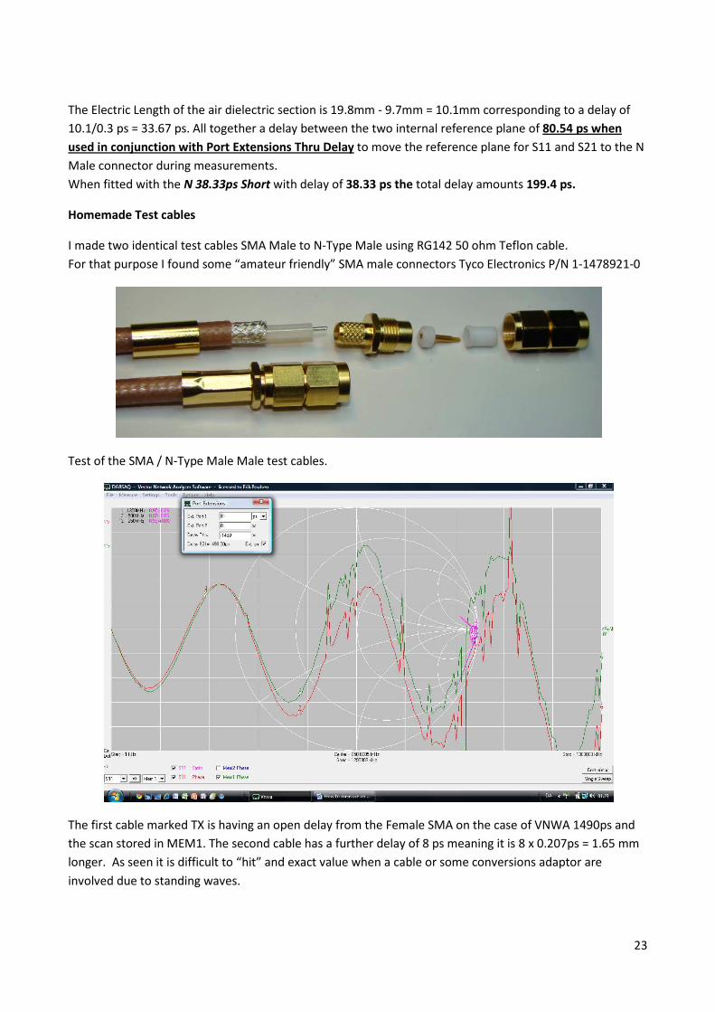
Calculated parameters for the Thru adaptor:
The Electric Length of the Teflon section is 9.7mm/0.69 =14.06mm or a delay of 46.87 ps
Teflon 9.7mm
Ref Plane 19.8mm
23
The Electric Length of the air dielectric section is 19.8mm - 9.7mm = 10.1mm corresponding to a delay of
10.1/0.3 ps = 33.67 ps. All together a delay between the two internal reference plane of 80.54 ps when
used in conjunction with Port Extensions Thru Delay to move the reference plane for S11 and S21 to the N
Male connector during measurements.
When fitted with the N 38.33ps Short with delay of 38.33 ps the total delay amounts 199.4 ps.
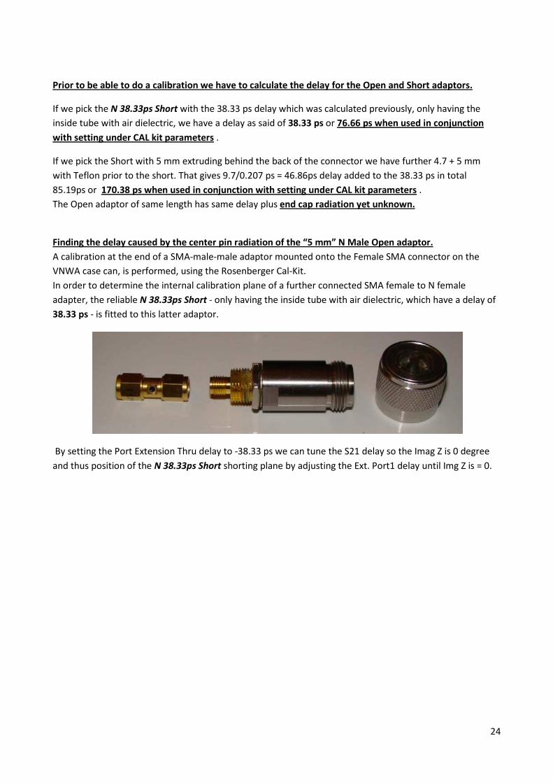
Homemade Test cables
I made two identical test cables SMA Male to N-Type Male using RG142 50 ohm Teflon cable.
For that purpose I found some “amateur friendly” SMA male connectors Tyco Electronics P/N 1-1478921-0
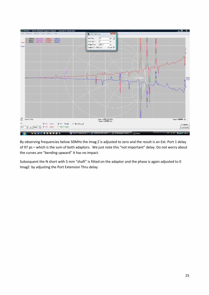
Test of the SMA / N-Type Male Male test cables.
The first cable marked TX is having an open delay from the Female SMA on the case of VNWA 1490ps and
the scan stored in MEM1. The second cable has a further delay of 8 ps meaning it is 8 x 0.207ps = 1.65 mm
longer. As seen it is difficult to “hit” and exact value when a cable or some conversions adaptor are
involved due to standing waves.
24
Prior to be able to do a calibration we have to calculate the delay for the Open and Short adaptors.
If we pick the N 38.33ps Short with the 38.33 ps delay which was calculated previously, only having the
inside tube with air dielectric, we have a delay as said of 38.33 ps or 76.66 ps when used in conjunction
with setting under CAL kit parameters .
If we pick the Short with 5 mm extruding behind the back of the connector we have further 4.7 + 5 mm
with Teflon prior to the short. That gives 9.7/0.207 ps = 46.86ps delay added to the 38.33 ps in total
85.19ps or 170.38 ps when used in conjunction with setting under CAL kit parameters .
The Open adaptor of same length has same delay plus end cap radiation yet unknown.
Finding the delay caused by the center pin radiation of the “5 mm” N Male Open adaptor.
A calibration at the end of a SMA-male-male adaptor mounted onto the Female SMA connector on the
VNWA case can, is performed, using the Rosenberger Cal-Kit.
In order to determine the internal calibration plane of a further connected SMA female to N female
adapter, the reliable N 38.33ps Short - only having the inside tube with air dielectric, which have a delay of
38.33 ps - is fitted to this latter adaptor.
By setting the Port Extension Thru delay to -38.33 ps we can tune the S21 delay so the Imag Z is 0 degree
and thus position of the N 38.33ps Short shorting plane by adjusting the Ext. Port1 delay until Img Z is = 0.
25
By observing frequencies below 50MHz the Imag Z is adjusted to zero and the result is an Ext. Port 1 delay
of 97 ps – which is the sum of both adaptors. We just note this “not important” delay. Do not worry about
the curves are “bending upward” it has no impact.
Subsequent the N short with 5 mm “shaft” is fitted on the adaptor and the phase is again adjusted to 0
ImagZ by adjusting the Port Extension Thru delay.
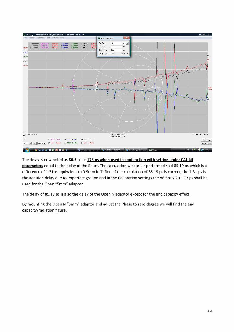
26
The delay is now noted as 86.5 ps or 173 ps when used in conjunction with setting under CAL kit
parameters equal to the delay of the Short. The calculation we earlier performed said 85.19 ps which is a
difference of 1.31ps equivalent to 0.9mm in Teflon. If the calculation of 85.19 ps is correct, the 1.31 ps is
the addition delay due to imperfect ground and in the Calibration settings the 86.5ps x 2 = 173 ps shall be
used for the Open “5mm” adaptor.
The delay of 85.19 ps is also the delay of the Open N adaptor except for the end capacity effect.
By mounting the Open N “5mm” adaptor and adjust the Phase to zero degree we will find the end
capacity/radiation figure.
27
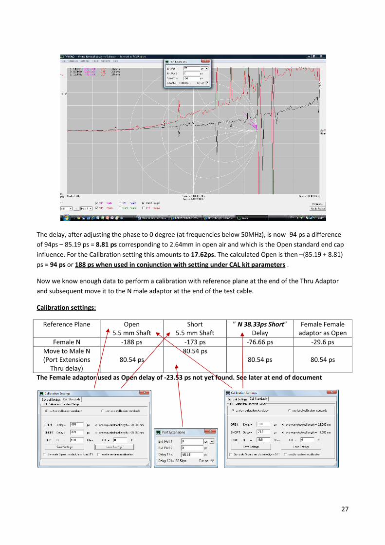
The delay, after adjusting the phase to 0 degree (at frequencies below 50MHz), is now -94 ps a difference
of 94ps – 85.19 ps = 8.81 ps corresponding to 2.64mm in open air and which is the Open standard end cap
influence. For the Calibration setting this amounts to 17.62ps. The calculated Open is then –(85.19 + 8.81)
ps = 94 ps or 188 ps when used in conjunction with setting under CAL kit parameters .
Now we know enough data to perform a calibration with reference plane at the end of the Thru Adaptor
and subsequent move it to the N male adaptor at the end of the test cable.
Calibration settings:
Reference Plane Open
5.5 mm Shaft
Short
5.5 mm Shaft
” N 38.33ps Short”
Delay
Female Female
adaptor as Open
Female N -188 ps -173 ps -76.66 ps -29.6 ps
Move to Male N
(Port Extensions
Thru delay)
80.54 ps
80.54 ps
80.54 ps 80.54 ps
The Female adaptor used as Open delay of -23.53 ps not yet found. See later at end of document
28
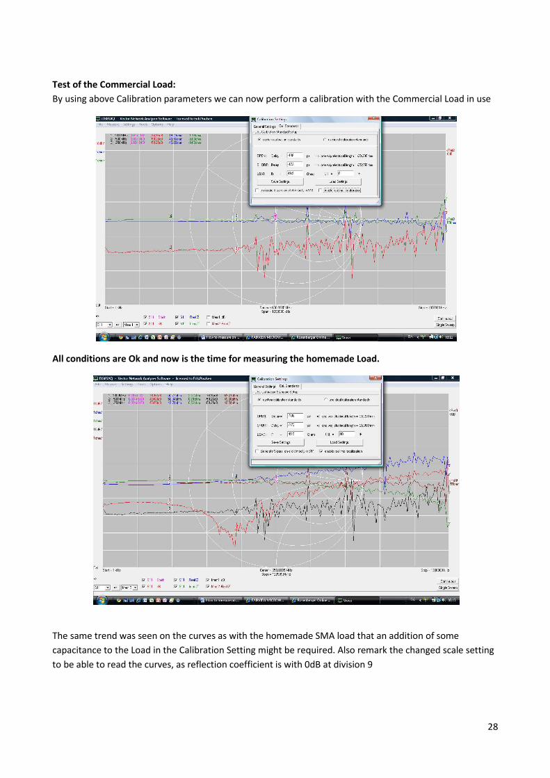
Test of the Commercial Load:
By using above Calibration parameters we can now perform a calibration with the Commercial Load in use
All conditions are Ok and now is the time for measuring the homemade Load.
The same trend was seen on the curves as with the homemade SMA load that an addition of some
capacitance to the Load in the Calibration Setting might be required. Also remark the changed scale setting
to be able to read the curves, as reflection coefficient is with 0dB at division 9
29
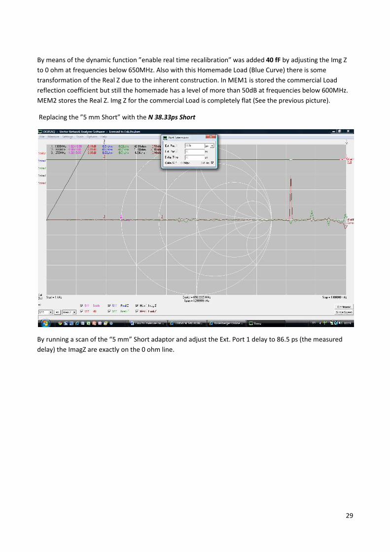
By means of the dynamic function ”enable real time recalibration” was added 40 fF by adjusting the Img Z
to 0 ohm at frequencies below 650MHz. Also with this Homemade Load (Blue Curve) there is some
transformation of the Real Z due to the inherent construction. In MEM1 is stored the commercial Load
reflection coefficient but still the homemade has a level of more than 50dB at frequencies below 600MHz.
MEM2 stores the Real Z. Img Z for the commercial Load is completely flat (See the previous picture).
Replacing the ”5 mm Short” with the N 38.33ps Short
By running a scan of the “5 mm” Short adaptor and adjust the Ext. Port 1 delay to 86.5 ps (the measured
delay) the ImagZ are exactly on the 0 ohm line.
30
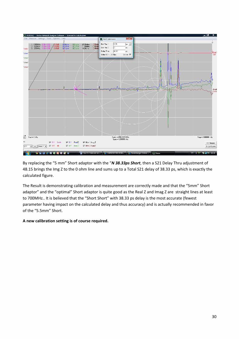
By replacing the “5 mm” Short adaptor with the “N 38.33ps Short, then a S21 Delay Thru adjustment of
48.15 brings the Img Z to the 0 ohm line and sums up to a Total S21 delay of 38.33 ps, which is exactly the
calculated figure.
The Result is demonstrating calibration and measurement are correctly made and that the “5mm” Short
adaptor” and the “optimal” Short adaptor is quite good as the Real Z and Imag Z are straight lines at least
to 700MHz.. It is believed that the “Short Short” with 38.33 ps delay is the most accurate (fewest
parameter having impact on the calculated delay and thus accuracy) and is actually recommended in favor
of the “5.5mm” Short.
A new calibration setting is of course required.
31
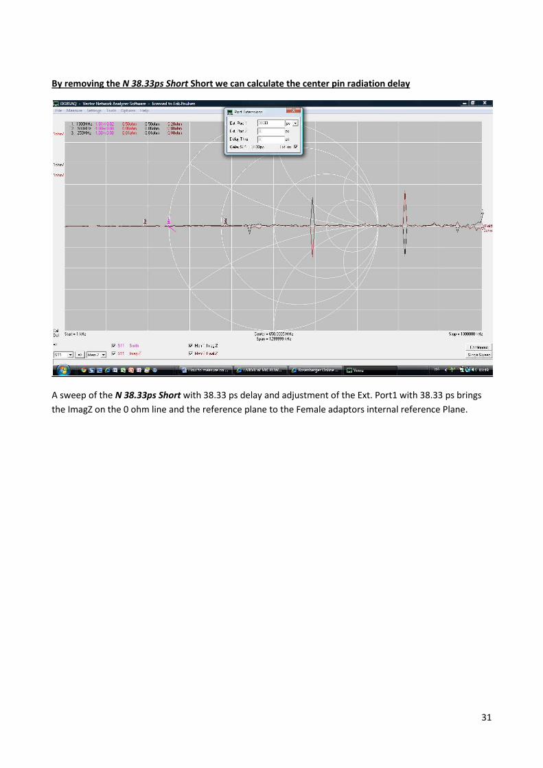
By removing the N 38.33ps Short Short we can calculate the center pin radiation delay
A sweep of the N 38.33ps Short with 38.33 ps delay and adjustment of the Ext. Port1 with 38.33 ps brings
the ImagZ on the 0 ohm line and the reference plane to the Female adaptors internal reference Plane.
32
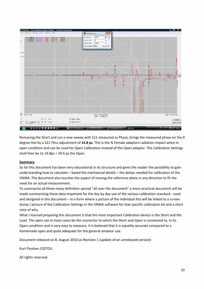
Removing the Short and run a new sweep with S11 measured as Phase, brings the measured phase on the 0
degree line by a S21 Thru adjustment of 14.8 ps. This is the N Female adaptors radiation impact when in
open condition and can be used for Open Calibration instead of the Open adaptor. The Calibration Settings
shall then be 2x 14.8ps = 29.6 ps the Open.
Summary
So far this document has been very educational in its structure and gives the reader the possibility to gain
understanding how to calculate – based the mechanical details – the delays needed for calibration of the
VNWA. The document also touches the aspect of moving the reference plane in any direction to fit the
need for an actual measurement.
To summarize all these many definition spread “all over the document” a more practical document will be
made summarizing these data important for the day by day use of the various calibration standard - used
and designed in this document – in a form where a picture of the individual Kits will be linked to a screen
dump / picture of the Calibration Settings in the VNWA software for that specific calibration kit and a short
note of why.
What I learned preparing this document is that the most important Calibration device is the Short and the
Load. The open can in most cases be the connector to which the Short and Open is connected to, in its
Open condition and is very easy to measure. It is believed that it is equality accurate compared to a
homemade open and quite adequate for the general amateur use.
Document released on 8. August 2010 as Revision 1 (update of an unreleased version)
Kurt Poulsen /OZ7OU
All rights reserved.