Embed Size (px)
Citation preview
Contents 1 Introduction ........................................................................................................... 2
1.1 ABOUT THIS NOTE ........................................................................................................................... 2
1.2 DIFFICULTY OF SCENARIO CREATION .................................................................................................. 2
2 Considerations for Creating Scenarios ................................................................ 4
2.1 TESTING MANAGER AND TESTING FIELD TECHNICIAN .......................................................................... 4
2.2 PREPARING FOR CREATING SCENARIOS ............................................................................................... 4
2.3 HANDLING VARIABLE PARAMETERS AND THRESHOLD VALUES ............................................................... 6
2.4 UPDATING SCENARIOS...................................................................................................................... 7
3 Sample Scenarios ................................................................................................... 8
3.1 ERROR-FREE COMMUNICATIONS TEST ................................................................................................ 9
3.2 COMMUNICATIONS TEST WITH ERROR INSERTION ............................................................................. 13
3.3 AUTOMATING LONG-TERM CONTINUOUS MEASUREMENT .................................................................. 18
3.4 TESTING CATEGORY 5 CABLE ........................................................................................................... 21
How To Create Scenarios Network Master Pro MT1000A Network Master Flex MT1100A Scenario Edit Environment Kit (SEEK) MX100003A
Application Note
2
1 Introduction
1.1 About This Note
This note describes the procedures and knowledge required for end users to create scenarios to automate tests using the MT1000A and MT1100A (Network Master hereafter). Readers with a good understanding of the contents will be able to create scenarios for controlling the Network Master.
This note explains the following:
・ General procedures and knowledge to prepare for creating and maintaining scenarios
・ Detailed explanations of sample scenarios
This note does not explain the following items; refer to the appended instruction manual for explanation of these items.
How to operate network master Refer to MT1000A or MT1100A instruction manual. SCPI command reference Refer to remote scripting instruction manual. How to use MX100003A Scenario Editing Kit Refer to MX100003A instruction manual. Scripts syntax and commands reference Refer to MX100003A instruction manual.
1.2 Difficulty of Scenario Creation
The MX100003A Scenario Editing Kit (SEEK) is a tool to support automating tests. Implementing automatic testing using general measuring instruments without SEEK requires deep knowledge, skills, and experience in the following areas.
・ Knowledge about command-line-based user interfaces called SCPI supported by measuring instruments
・ Knowledge and experience of software programming using languages, such as C/C++, Visual Basic, Python, Ruby, etc.
Using these types of knowledge for programming automation objectives is a strength. Conversely, sections performing and managing testing must secure staff with the necessary software development skills.
The SEEK has been developed to implement automation using a drag and drop GUI without the need for the above-described knowledge and experience. The SEEK GUI is used to create scenarios on-screen based on operation sequences and pass/fail evaluation standards to be automated.
Scenario descriptions are simple to create using general GUI operations, but on the other hand, there may be limits to the descriptions. Descriptions created using programming languages have no limits, but on the other hand, can be extremely hard to use. SEEK eliminates this trade-off by introducing a unique scripting language in addition to GUI operations. It is easy to obtain this scripting language due to its small size. This combination of sequence description using a GUI and scripting language offers users the best balance of both methods.
3
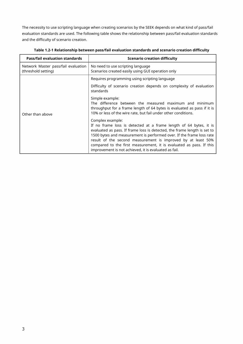
The necessity to use scripting language when creating scenarios by the SEEK depends on what kind of pass/fail evaluation standards are used. The following table shows the relationship between pass/fail evaluation standards and the difficulty of scenario creation.
Table 1.2-1 Relationship between pass/fail evaluation standards and scenario creation difficulty
Pass/fail evaluation standards Scenario creation difficulty
Network Master pass/fail evaluation (threshold setting)
No need to use scripting language Scenarios created easily using GUI operation only
Other than above
Requires programming using scripting language
Difficulty of scenario creation depends on complexity of evaluation standards
Simple example: The difference between the measured maximum and minimum throughput for a frame length of 64 bytes is evaluated as pass if it is 10% or less of the wire rate, but fail under other conditions.
Complex example: If no frame loss is detected at a frame length of 64 bytes, it is evaluated as pass. If frame loss is detected, the frame length is set to 1500 bytes and measurement is performed over. If the frame loss rate result of the second measurement is improved by at least 50% compared to the first measurement, it is evaluated as pass. If this improvement is not achieved, it is evaluated as fail.
4
2 Considerations for Creating Scenarios This section explains some general considerations and recommended procedures for creating scenarios.
2.1 Testing Manager and Testing Field Technician
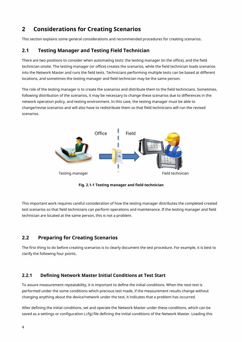
There are two positions to consider when automating tests: the testing manager (in the office), and the field technician onsite. The testing manager (or office) creates the scenarios, while the field technician loads scenarios into the Network Master and runs the field tests. Technicians performing multiple tests can be based at different locations, and sometimes the testing manager and field technician may be the same person.
The role of the testing manager is to create the scenarios and distribute them to the field technicians. Sometimes, following distribution of the scenarios, it may be necessary to change these scenarios due to differences in the network operation policy, and testing environment. In this case, the testing manager must be able to change/revise scenarios and will also have to redistribute them so that field technicians will run the revised scenarios.
Fig. 2.1-1 Testing manager and field technician
This important work requires careful consideration of how the testing manager distributes the completed created test scenarios so that field technicians can perform operations and maintenance. If the testing manager and field technician are located at the same person, this is not a problem.
2.2 Preparing for Creating Scenarios
The first thing to do before creating scenarios is to clearly document the test procedure. For example, it is best to clarify the following four points.
2.2.1 Defining Network Master Initial Conditions at Test Start
To assure measurement repeatability, it is important to define the initial conditions. When the next test is performed under the some conditions which precious test made, if the measurement results change without changing anything about the device/network under the test, it indicates that a problem has occurred.
After defining the initial conditions, set and operate the Network Master under these conditions, which can be saved as a settings or configuration (.cfg) file defining the initial conditions of the Network Master. Loading this
Office Field
Testing manager Field technician
5
configuration file before the scenario assures testing under the same conditions every time. If no Network Master is available, this settings or configuration file can be created on a PC using the MX100001A software, which can be downloaded free-of-charge from the Anritsu website.
2.2.2 Examining Parameters
What settings cannot be determined at scenario creation? As an example, the IP address of the equipment to which the Network Master will be connected changes at each measurement site and cannot be determined until actual testing starts. Occasionally, a scenario may be created in which all measurement sites have a common fixed IP address, but this usage may change with time.
So how do we examine these variable parameters and clarify the reasons and changes at fault conditions? It is best to consider them from various viewpoints, such as changes with time, changes with location, changes due to unknown factors (accuracy), changes due to test frequency (quarterly measurements, etc.). It is also good to describe items that can change simultaneously.
2.2.3 Visualizing Test Procedure
Visualize the test procedure using a flowchart. It is best to start from powering-up the device to be tested (DUT) and the Network Master. It is important to be clear about manual operation procedures before and after connecting cables. When powering-up equipment before and after connecting cables, there may be differences in the obtained measurement results.
It is important to understand complex flow procedures when there are many alternative conditions. When describing these types of procedure using one scenario, the scenario can become extremely complex, making post-testing maintenance difficult. In these cases, it is better to re-examine the procedure and split the scenario into several scenarios.
2.2.4 Defining Pass/Fail Standards
This section explains the basics of a passing test.
The Network Master has a pass/fail evaluation function using standard counter items. This tutorial first explains use of this function, which simplifies scenario creation. Select “Summary” at the GUI and read section 3.4.7.8 Judge of the MX100003A instruction manual for an explanation.
If the pass/fail evaluation is complex, consider whether it can be simplified. For example, at evaluation when the threshold value is XX when there is a VLAN and YY when there is no VLAN, this scenario can be greatly simplified by splitting into two scenarios one with the VLAN, And one without the VLAN. Or in this case, it may be more efficient for the field technician to perform pass/fail evaluation by eye and omit automatic evaluation. In this latter case, create a scenario to display the message “Confirm XXX is YYY. OK/NG”.
In both these examples, although the scenarios are simple, the field technician has more work to do, increasing the risk of human error. When performing evaluations, it is important to consider the balance between the cost of creating and maintaining the scenario and the operation cost.
Like the previously described test parameters, there are cases where the pass/fail threshold values cannot be decided at scenario creation. In these cases, it is best to document the reasons for the variability and the range.

6
2.3 Handling Variable Parameters and Threshold Values
As explained previously, sometimes setting parameters and threshold values either cannot be decided at scenario creation, or may change in the future. There are two methods for dealing with these types of variable factors.
(1) Allocating Global Variables
Use the function explained in section 3.4.4 Global Variable of the MX100003A instruction manual. Since, unlike local variables, the value of a global variable can be changed at a Network Master screen, this function makes it unnecessary to update and redistribute scenarios. The changed value is backed-up, so it is saved after restarting the Network Master. It can be locked with a password, preventing the field technician changing it in error.
Use of global variables is convenient when parameter settings change with test site. For example, when the parameter is different between sites A and B, two Network Master units are used—one at each site. In this case, the site-dependent parameters are set in each Network Master, supporting integrated testing at all sites.
There are some precautions regarding global variables; if the same scenarios are re-registered in a Network Master, when the scenario is updated, the values saved in the main frame are initialized. As a result, the last updated value is in error. It is necessary to manage conditions when changing global variables. Refer to section 2.4 Updating Scenarios in this note for how to transfer global variables when updating scenarios.
(2) Questioning Field Technician Running Test Scenarios
One scenario command is use of “Message”. Executing this command while executing a scenario, displays a dialog box on the Network Master screen requesting input by the field technician.
This is convenient if values cannot be decided before the test start date, or if there may be small changes in the values depending on circumstances. However, too many of these input messages increases the work of the field technician, which may increase the chance of operation errors. Consequently, it is better not to use too many Message questions for field technicians.
7
2.4 Updating Scenarios
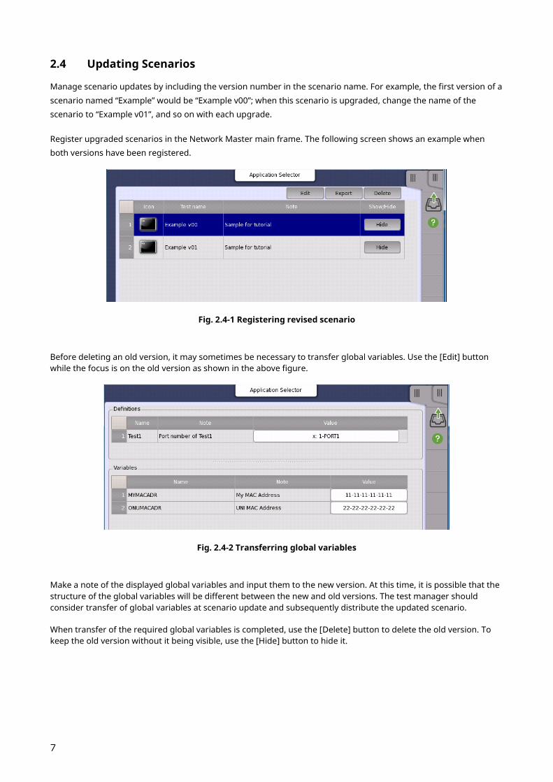
Manage scenario updates by including the version number in the scenario name. For example, the first version of a scenario named “Example” would be “Example v00”; when this scenario is upgraded, change the name of the scenario to “Example v01”, and so on with each upgrade.
Register upgraded scenarios in the Network Master main frame. The following screen shows an example when both versions have been registered.
Fig. 2.4-1 Registering revised scenario
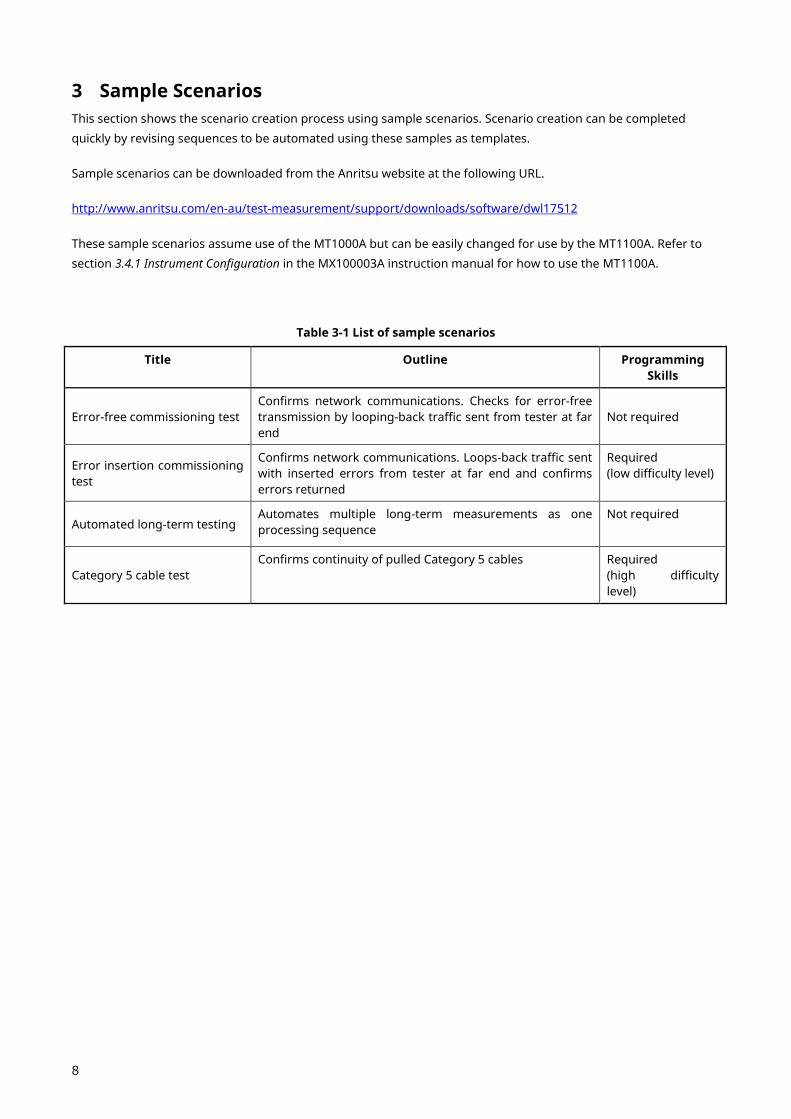
Before deleting an old version, it may sometimes be necessary to transfer global variables. Use the [Edit] button while the focus is on the old version as shown in the above figure.
Fig. 2.4-2 Transferring global variables
Make a note of the displayed global variables and input them to the new version. At this time, it is possible that the structure of the global variables will be different between the new and old versions. The test manager should consider transfer of global variables at scenario update and subsequently distribute the updated scenario.
When transfer of the required global variables is completed, use the [Delete] button to delete the old version. To keep the old version without it being visible, use the [Hide] button to hide it.
8
3 Sample Scenarios This section shows the scenario creation process using sample scenarios. Scenario creation can be completed quickly by revising sequences to be automated using these samples as templates.
Sample scenarios can be downloaded from the Anritsu website at the following URL.
http://www.anritsu.com/en-au/test-measurement/support/downloads/software/dwl17512
These sample scenarios assume use of the MT1000A but can be easily changed for use by the MT1100A. Refer to section 3.4.1 Instrument Configuration in the MX100003A instruction manual for how to use the MT1100A.
Table 3-1 List of sample scenarios
Title Outline Programming Skills
Error-free commissioning test Confirms network communications. Checks for error-free transmission by looping-back traffic sent from tester at far end
Not required
Error insertion commissioning test
Confirms network communications. Loops-back traffic sent with inserted errors from tester at far end and confirms errors returned
Required (low difficulty level)
Automated long-term testing Automates multiple long-term measurements as one processing sequence
Not required
Category 5 cable test Confirms continuity of pulled Category 5 cables Required
(high difficulty level)
9
3.1 Error-free Communications Test
3.1.1 Test Objective
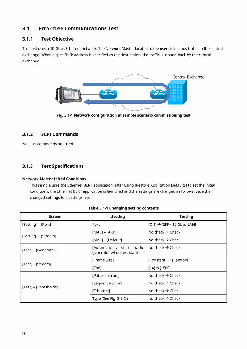
This test uses a 10-Gbps Ethernet network. The Network Master located at the user side sends traffic to the central exchange. When a specific IP address is specified as the destination, the traffic is looped-back by the central exchange.
Fig. 3.1-1 Network configuration at sample scenario commissioning test
3.1.2 SCPI Commands
No SCPI commands are used.
3.1.3 Test Specifications
Network Master Initial Conditions This sample uses the Ethernet BERT application; after using [Restore Application Defaults] to set the initial conditions, the Ethernet BERT application is launched and the settings are changed as follows. Save the changed settings to a settings file.
Table 3.1-1 Changing setting contents
Screen Setting Setting
[Setting] – [Port] Port [Off] [SFP+ 10 Gbps LAN]
[Setting] – [Stream] [MAC] – [ARP] No check Check
[MAC] – [Default] No check Check
[Test] – [Generator] [Automatically start traffic generator when test started
No check Check
[Test] – [Stream] [Frame Size] [Constant] [Random]
[End] [64] [1500]
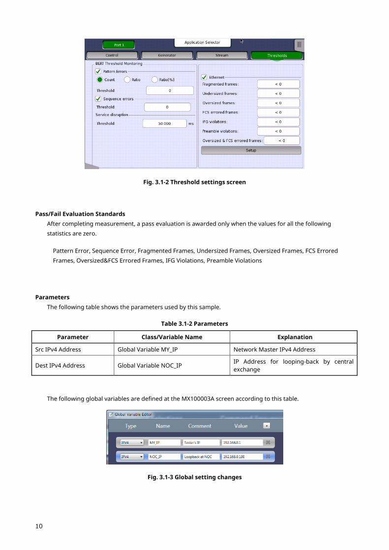
[Test] – [Thresholds]
[Pattern Errors] No check Check
[Sequence Errors] No check Check
[Ethernet] No check Check
Type (See Fig. 3.1-2.) No check Check
Central Exchange
10
Fig. 3.1-2 Threshold settings screen
Pass/Fail Evaluation Standards After completing measurement, a pass evaluation is awarded only when the values for all the following statistics are zero.
Pattern Error, Sequence Error, Fragmented Frames, Undersized Frames, Oversized Frames, FCS Errored Frames, Oversized&FCS Errored Frames, IFG Violations, Preamble Violations
Parameters The following table shows the parameters used by this sample.
Table 3.1-2 Parameters
Parameter Class/Variable Name Explanation
Src IPv4 Address Global Variable MY_IP Network Master IPv4 Address
Dest IPv4 Address Global Variable NOC_IP IP Address for looping-back by central exchange
The following global variables are defined at the MX100003A screen according to this table.
Fig. 3.1-3 Global setting changes
11
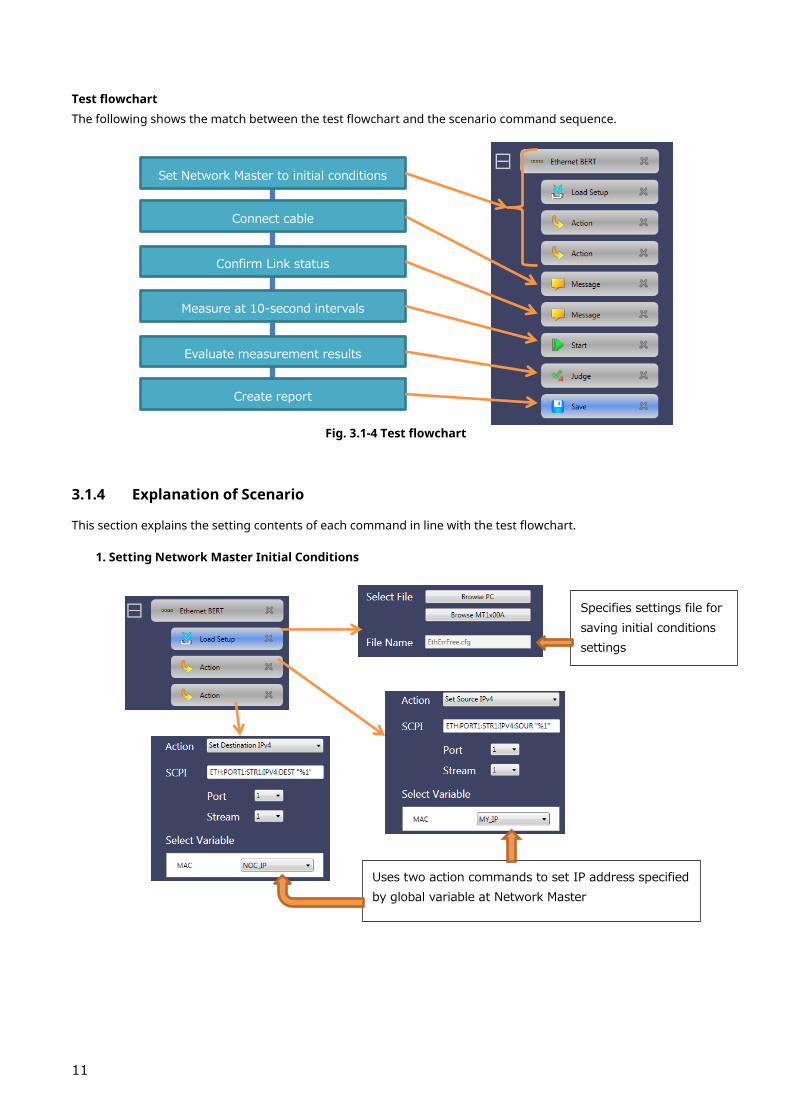
Test flowchart The following shows the match between the test flowchart and the scenario command sequence.
Fig. 3.1-4 Test flowchart
3.1.4 Explanation of Scenario
This section explains the setting contents of each command in line with the test flowchart.
1. Setting Network Master Initial Conditions
Specifies settings file for
saving initial conditions
settings
Uses two action commands to set IP address specified
by global variable at Network Master
Set Network Master to initial conditions
Connect cable
Measure at 10-second intervals
Evaluate measurement results
Confirm Link status
Create report
12
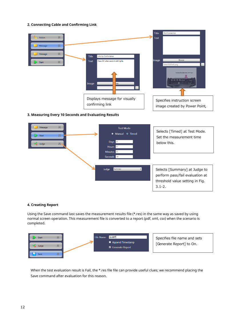
2. Connecting Cable and Confirming Link
3. Measuring Every 10 Seconds and Evaluating Results
4. Creating Report
Using the Save command last saves the measurement results file (*.res) in the same way as saved by using normal screen operation. This measurement file is converted to a report (pdf, xml, csv) when the scenario is completed.
When the test evaluation result is Fail, the *.res file file can provide useful clues; we recommend placing the Save command after evaluation for this reason.
Specifies instruction screen
image created by Power Point,
etc.
Displays message for visually
confirming link
Selects [Timed] at Test Mode.
Set the measurement time
below this.
Selects [Summary] at Judge to
perform pass/fail evaluation at
threshold value setting in Fig.
3.1-2.
Specifies file name and sets
[Generate Report] to On.
13
3.2 Communications Test with Error Insertion
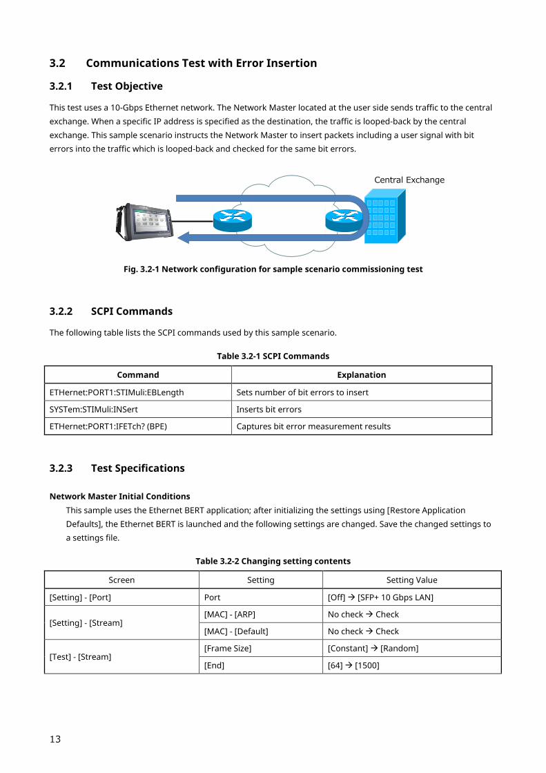
3.2.1 Test Objective
This test uses a 10-Gbps Ethernet network. The Network Master located at the user side sends traffic to the central exchange. When a specific IP address is specified as the destination, the traffic is looped-back by the central exchange. This sample scenario instructs the Network Master to insert packets including a user signal with bit errors into the traffic which is looped-back and checked for the same bit errors.
Fig. 3.2-1 Network configuration for sample scenario commissioning test
3.2.2 SCPI Commands
The following table lists the SCPI commands used by this sample scenario.
Table 3.2-1 SCPI Commands
Command Explanation
ETHernet:PORT1:STIMuli:EBLength Sets number of bit errors to insert
SYSTem:STIMuli:INSert Inserts bit errors
ETHernet:PORT1:IFETch? (BPE) Captures bit error measurement results
3.2.3 Test Specifications
Network Master Initial Conditions This sample uses the Ethernet BERT application; after initializing the settings using [Restore Application Defaults], the Ethernet BERT is launched and the following settings are changed. Save the changed settings to a settings file.
Table 3.2-2 Changing setting contents
Screen Setting Setting Value
[Setting] - [Port] Port [Off] [SFP+ 10 Gbps LAN]
[Setting] - [Stream] [MAC] - [ARP] No check Check
[MAC] - [Default] No check Check
[Test] - [Stream] [Frame Size] [Constant] [Random]
[End] [64] [1500]
Central Exchange
14
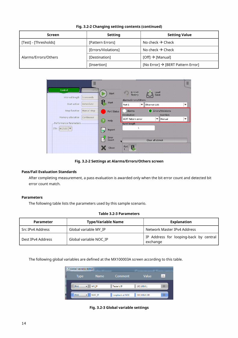
Fig. 3.2-2 Changing setting contents (continued)
Screen Setting Setting Value
[Test] - [Thresholds] [Pattern Errors] No check Check
Alarms/Errors/Others
[Errors/Violations] No check Check
[Destination] [Off] [Manual]
[Insertion] [No Error] [BERT Pattern Error]
Fig. 3.2-2 Settings at Alarms/Errors/Others screen
Pass/Fail Evaluation Standards After completing measurement, a pass evaluation is awarded only when the bit error count and detected bit error count match.
Parameters The following table lists the parameters used by this sample scenario.
Table 3.2-3 Parameters
Parameter Type/Variable Name Explanation
Src IPv4 Address Global variable MY_IP Network Master IPv4 Address
Dest IPv4 Address Global variable NOC_IP IP Address for looping-back by central exchange
The following global variables are defined at the MX100003A screen according to this table.
Fig. 3.2-3 Global variable settings
15
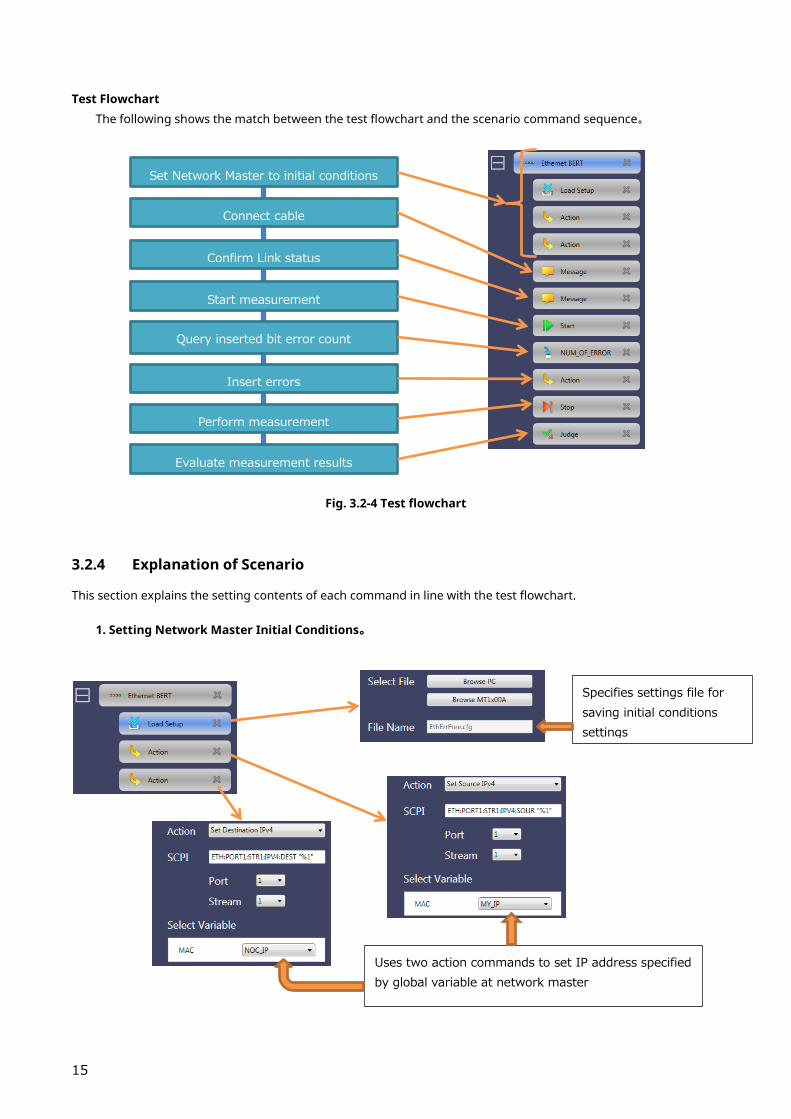
Test Flowchart The following shows the match between the test flowchart and the scenario command sequence。
Fig. 3.2-4 Test flowchart
3.2.4 Explanation of Scenario
This section explains the setting contents of each command in line with the test flowchart.
1. Setting Network Master Initial Conditions。
Set Network Master to initial conditions
Connect cable
Start measurement
Query inserted bit error count
Confirm Link status
Insert errors
Perform measurement
Evaluate measurement results
Specifies settings file for
saving initial conditions
settings
Uses two action commands to set IP address specified
by global variable at network master
16
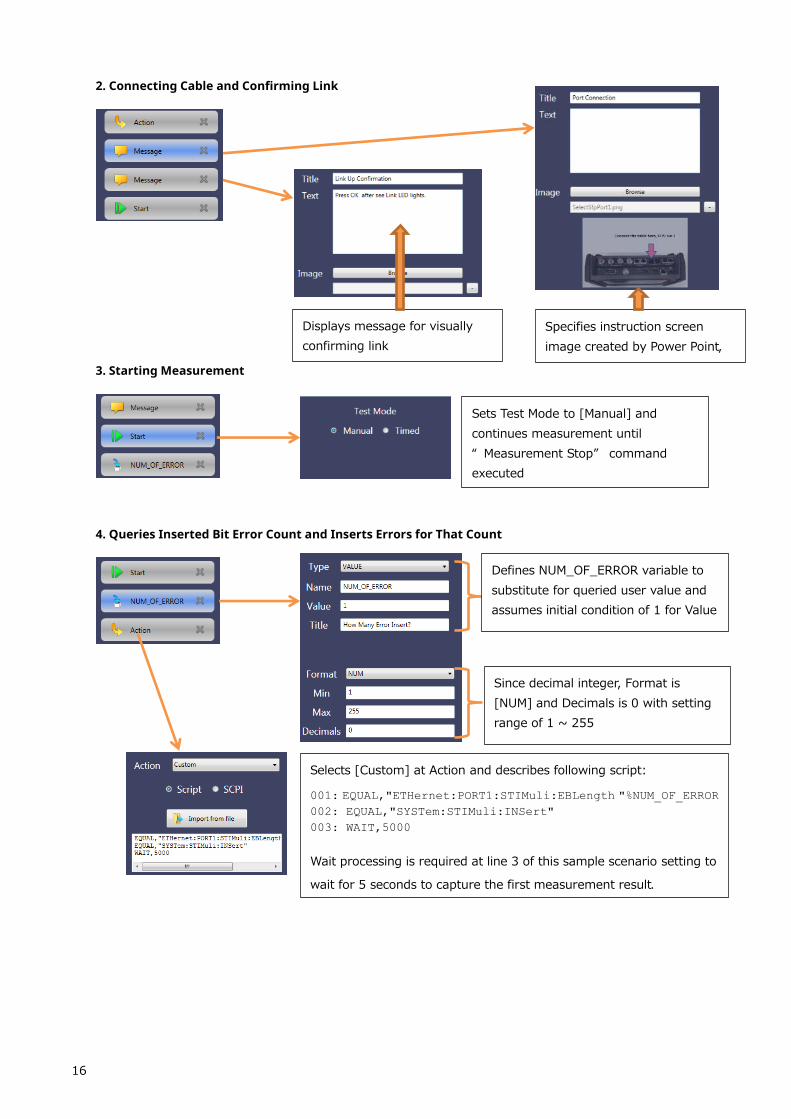
2. Connecting Cable and Confirming Link
3. Starting Measurement
4. Queries Inserted Bit Error Count and Inserts Errors for That Count
Displays message for visually
confirming link
。
Specifies instruction screen
image created by Power Point,
etc.
Sets Test Mode to [Manual] and
continues measurement until
“ Measurement Stop” command
executed
Defines NUM_OF_ERROR variable to
substitute for queried user value and
assumes initial condition of 1 for Value
Since decimal integer, Format is
[NUM] and Decimals is 0 with setting
range of 1 ~ 255
Selects [Custom] at Action and describes following script:
001: EQUAL,"ETHernet:PORT1:STIMuli:EBLength "%NUM_OF_ERROR
002: EQUAL,"SYSTem:STIMuli:INSert"
003: WAIT,5000
Wait processing is required at line 3 of this sample scenario setting to
wait for 5 seconds to capture the first measurement result.
17
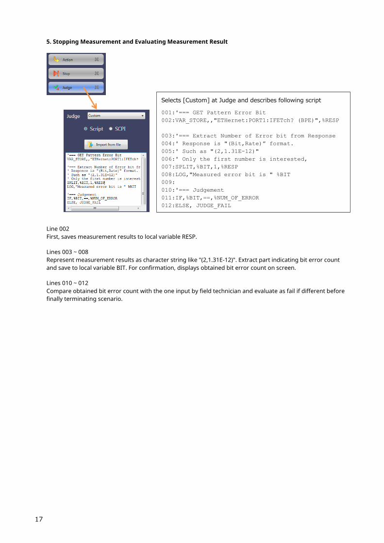
5. Stopping Measurement and Evaluating Measurement Result
Line 002 First, saves measurement results to local variable RESP.
Lines 003 ~ 008 Represent measurement results as character string like "(2,1.31E-12)". Extract part indicating bit error count and save to local variable BIT. For confirmation, displays obtained bit error count on screen.
Lines 010 ~ 012 Compare obtained bit error count with the one input by field technician and evaluate as fail if different before finally terminating scenario.
Selects [Custom] at Judge and describes following script
001:'=== GET Pattern Error Bit
002:VAR_STORE,,"ETHernet:PORT1:IFETch? (BPE)",%RESP
003:'=== Extract Number of Error bit from Response
004:' Response is "(Bit,Rate)” format.
005:' Such as "(2,1.31E-12)"
006:' Only the first number is interested,
007:SPLIT,%BIT,1,%RESP
008:LOG,"Measured error bit is " %BIT
009:
010:'=== Judgement
011:IF,%BIT,==,%NUM_OF_ERROR
012:ELSE, JUDGE_FAIL
18
3.3 Automating Long-Term Continuous Measurement
3.3.1 Test Objective
When long-term test taking 8 hours for example has many test runs under different conditions, procedures are required to save measurements, and change the conditions and restart measurement every 8 hours. This sample scenario automates this continuing process to obtain three sets of test results each 24 hours (every 8 hours) without manual intervention. Each test is conducted with different frame size, 64 bytes, 256 bytes and 1518 bytes.
3.3.2 SCPI Commands
No SCPI commands are used.
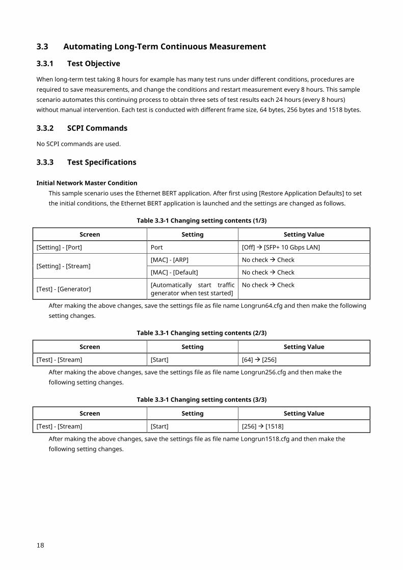
3.3.3 Test Specifications
Initial Network Master Condition This sample scenario uses the Ethernet BERT application. After first using [Restore Application Defaults] to set the initial conditions, the Ethernet BERT application is launched and the settings are changed as follows.
Table 3.3-1 Changing setting contents (1/3)
Screen Setting Setting Value
[Setting] - [Port] Port [Off] [SFP+ 10 Gbps LAN]
[Setting] - [Stream] [MAC] - [ARP] No check Check
[MAC] - [Default] No check Check
[Test] - [Generator] [Automatically start traffic generator when test started]
No check Check
After making the above changes, save the settings file as file name Longrun64.cfg and then make the following setting changes.
Table 3.3-1 Changing setting contents (2/3)
Screen Setting Setting Value
[Test] - [Stream] [Start] [64] [256]
After making the above changes, save the settings file as file name Longrun256.cfg and then make the following setting changes.
Table 3.3-1 Changing setting contents (3/3)
Screen Setting Setting Value
[Test] - [Stream] [Start] [256] [1518]
After making the above changes, save the settings file as file name Longrun1518.cfg and then make the following setting changes.
19
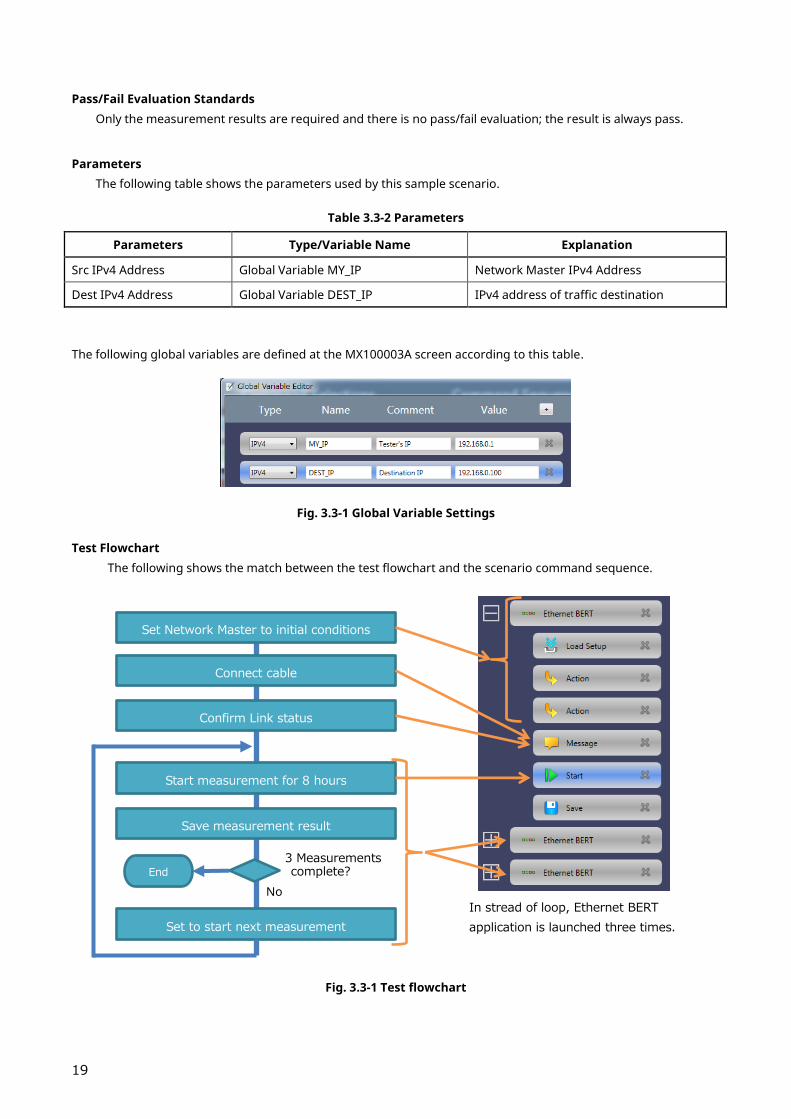
Pass/Fail Evaluation Standards Only the measurement results are required and there is no pass/fail evaluation; the result is always pass.
Parameters The following table shows the parameters used by this sample scenario.
Table 3.3-2 Parameters
Parameters Type/Variable Name Explanation
Src IPv4 Address Global Variable MY_IP Network Master IPv4 Address
Dest IPv4 Address Global Variable DEST_IP IPv4 address of traffic destination
The following global variables are defined at the MX100003A screen according to this table.
Fig. 3.3-1 Global Variable Settings
Test Flowchart The following shows the match between the test flowchart and the scenario command sequence.
Fig. 3.3-1 Test flowchart
Set Network Master to initial conditions
Connect cable
Start measurement for 8 hours
Save measurement result
Confirm Link status
Set to start next measurement
End
3 Measurements complete?
No
In stread of loop, Ethernet BERT
application is launched three times.
20
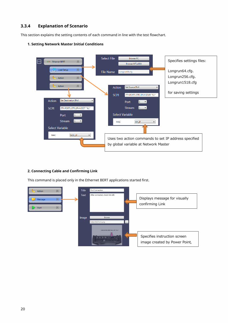
3.3.4 Explanation of Scenario
This section explains the setting contents of each command in line with the test flowchart.
1. Setting Network Master Initial Conditions
2. Connecting Cable and Confirming Link
This command is placed only in the Ethernet BERT applications started first.
Specifies instruction screen
image created by Power Point,
etc.
Displays message for visually
confirming Link
Specifies settings files:
Longrun64.cfg、
Longrun256.cfg、
Longrun1518.cfg
for saving settings
Uses two action commands to set IP address specified
by global variable at Network Master
21
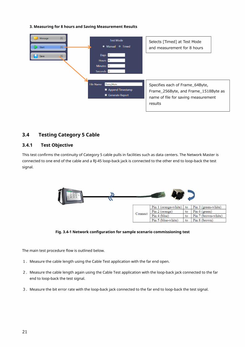
3. Measuring for 8 hours and Saving Measurement Results
3.4 Testing Category 5 Cable
3.4.1 Test Objective
This test confirms the continuity of Category 5 cable pulls in facilities such as data centers. The Network Master is connected to one end of the cable and a RJ-45 loop-back jack is connected to the other end to loop-back the test signal.
Fig. 3.4-1 Network configuration for sample scenario commissioning test
The main test procedure flow is outlined below.
1.Measure the cable length using the Cable Test application with the far end open.
2.Measure the cable length again using the Cable Test application with the loop-back jack connected to the far end to loop-back the test signal.
3.Measure the bit error rate with the loop-back jack connected to the far end to loop-back the test signal.
Selects [Timed] at Test Mode
and measurement for 8 hours
Specifies each of Frame_64Byte,
Frame_256Byte, and Frame_1518Byte as
name of file for saving measurement
results
22
3.4.2 SCPI Commands
The following table lists the SCPI commands used by this sample scenario.
Table 3.4-1 SCPI Commands
Command Explanation
ETHernet:CABLe:RESults:PAIR<Pr>? Queries Cable Test Application measurement results
ETH:STAT:PORT1:LINK? Queries Ethernet Link status
ETHernet:PORT1:STReam:PAYLoad Sets Ethernet sent traffic pattern
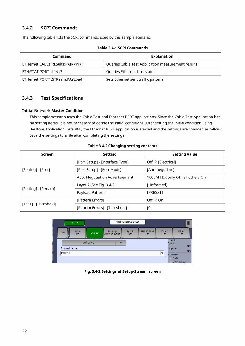
3.4.3 Test Specifications
Initial Network Master Condition This sample scenario uses the Cable Test and Ethernet BERT applications. Since the Cable Test Application has no setting items, it is not necessary to define the initial conditions. After setting the initial condition using [Restore Application Defaults], the Ethernet BERT application is started and the settings are changed as follows. Save the settings to a file after completing the settings.
Table 3.4-2 Changing setting contents
Screen Setting Setting Value
[Setting] - [Port]
[Port Setup] - [Interface Type] Off [Electrical]
[Port Setup] - [Port Mode] [Autonegotiate]
Auto Negotiation Advertisement 1000M FDX only Off; all others On
[Setting] - [Stream] Layer 2 (See Fig. 3.4-2.) [Unframed]
Payload Pattern [PRBS31]
[TEST] - [Threshold] [Pattern Errors] Off On
[Pattern Errors] - [Threshold] [0]
Fig. 3.4-2 Settings at Setup-Stream screen
23
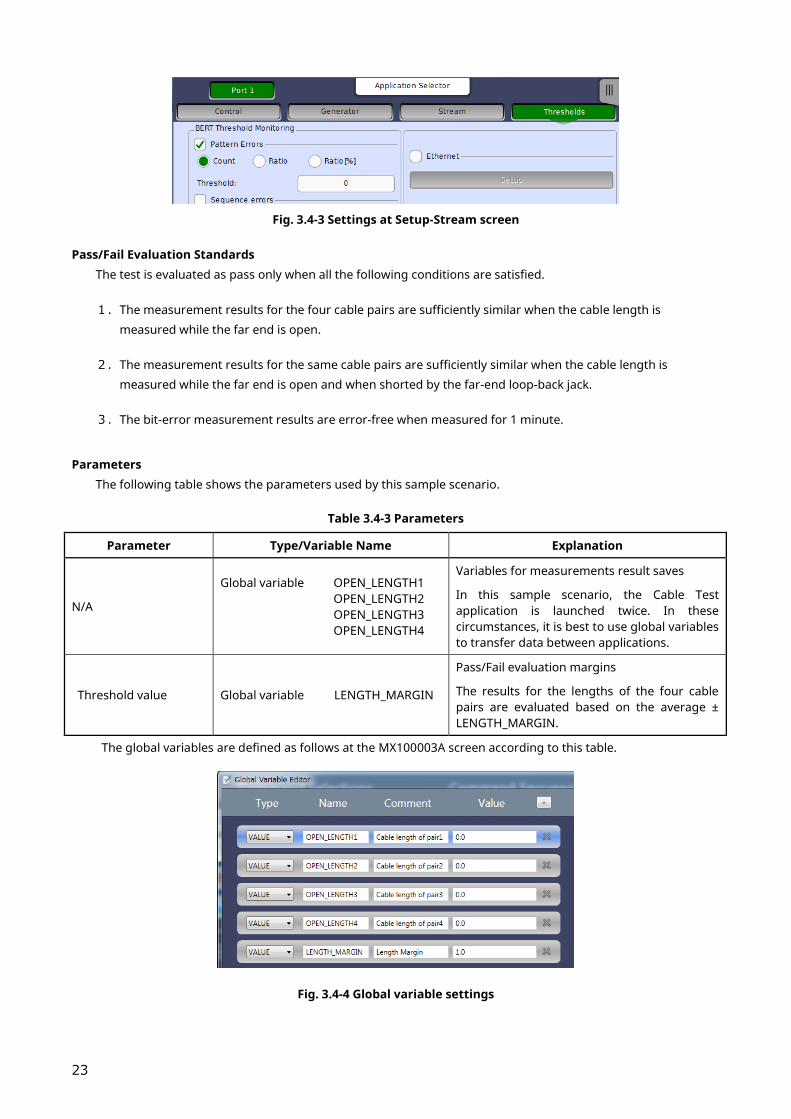
Fig. 3.4-3 Settings at Setup-Stream screen
Pass/Fail Evaluation Standards The test is evaluated as pass only when all the following conditions are satisfied.
1.The measurement results for the four cable pairs are sufficiently similar when the cable length is measured while the far end is open.
2.The measurement results for the same cable pairs are sufficiently similar when the cable length is measured while the far end is open and when shorted by the far-end loop-back jack.
3.The bit-error measurement results are error-free when measured for 1 minute.
Parameters The following table shows the parameters used by this sample scenario.
Table 3.4-3 Parameters
Parameter Type/Variable Name Explanation
N/A
Global variable OPEN_LENGTH1 OPEN_LENGTH2 OPEN_LENGTH3 OPEN_LENGTH4
Variables for measurements result saves
In this sample scenario, the Cable Test application is launched twice. In these circumstances, it is best to use global variables to transfer data between applications.
Threshold value Global variable LENGTH_MARGIN
Pass/Fail evaluation margins
The results for the lengths of the four cable pairs are evaluated based on the average ± LENGTH_MARGIN.
The global variables are defined as follows at the MX100003A screen according to this table.
Fig. 3.4-4 Global variable settings
24
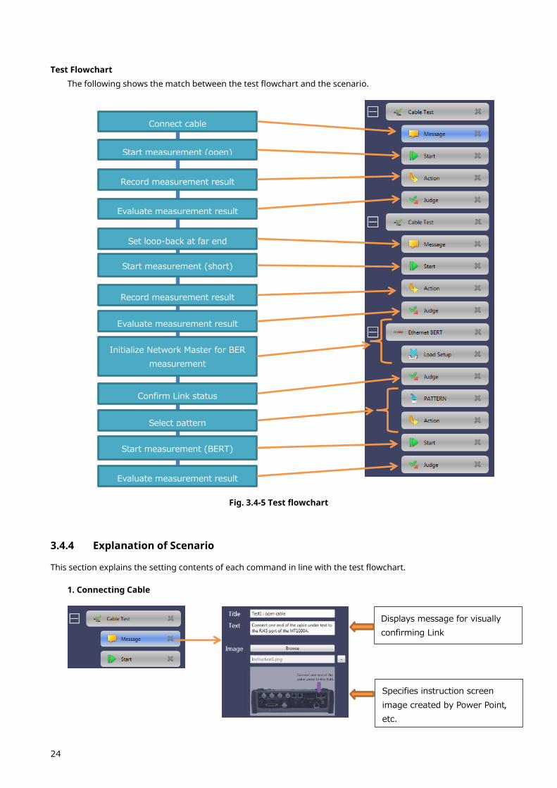
Test Flowchart The following shows the match between the test flowchart and the scenario.
Fig. 3.4-5 Test flowchart
3.4.4 Explanation of Scenario
This section explains the setting contents of each command in line with the test flowchart.
1. Connecting Cable
Connect cable
Start measurement (open)
Evaluate measurement result
Set loop-back at far end
Record measurement result
Start measurement (short)
Record measurement result
Initialize Network Master for BER
measurement
Evaluate measurement result
Confirm Link status
Select pattern
Start measurement (BERT)
Evaluate measurement result
Specifies instruction screen
image created by Power Point,
etc.
Displays message for visually
confirming Link
25
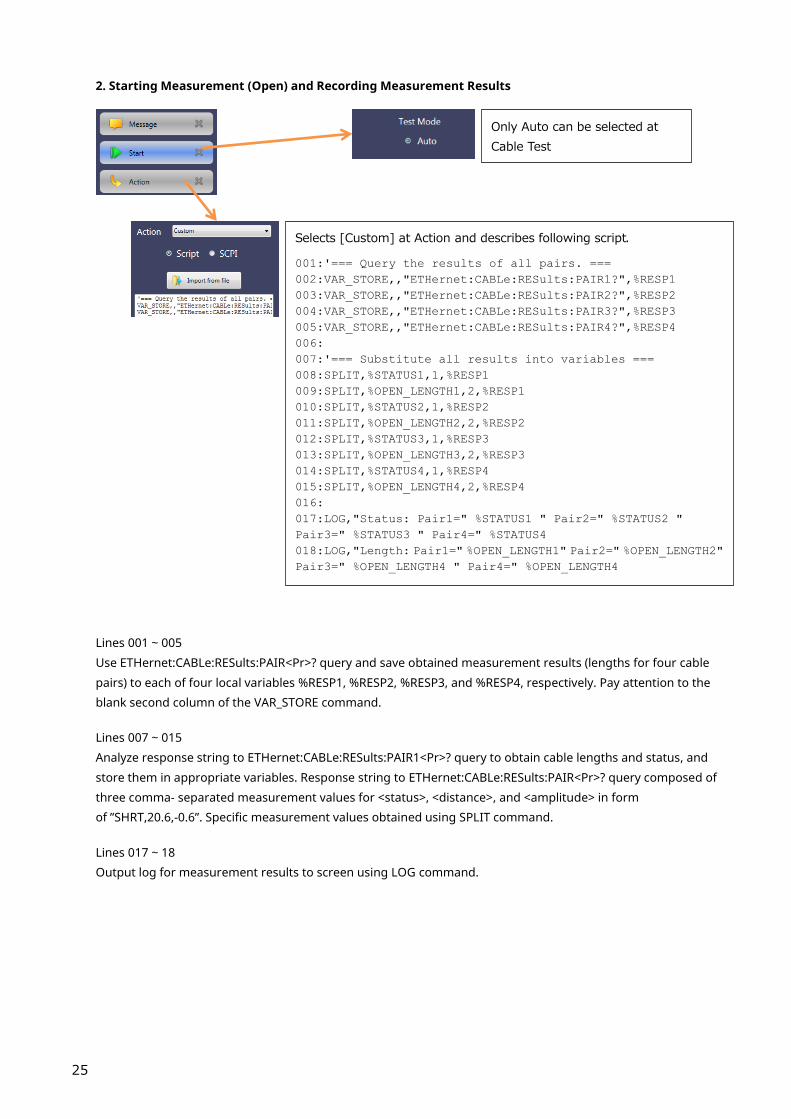
2. Starting Measurement (Open) and Recording Measurement Results
Lines 001 ~ 005 Use ETHernet:CABLe:RESults:PAIR<Pr>? query and save obtained measurement results (lengths for four cable pairs) to each of four local variables %RESP1, %RESP2, %RESP3, and %RESP4, respectively. Pay attention to the blank second column of the VAR_STORE command.
Lines 007 ~ 015 Analyze response string to ETHernet:CABLe:RESults:PAIR1<Pr>? query to obtain cable lengths and status, and store them in appropriate variables. Response string to ETHernet:CABLe:RESults:PAIR<Pr>? query composed of three comma- separated measurement values for <status>, <distance>, and <amplitude> in form of ”SHRT,20.6,-0.6”. Specific measurement values obtained using SPLIT command.
Lines 017 ~ 18 Output log for measurement results to screen using LOG command.
Selects [Custom] at Action and describes following script.
001:'=== Query the results of all pairs. ===
002:VAR_STORE,,"ETHernet:CABLe:RESults:PAIR1?",%RESP1
003:VAR_STORE,,"ETHernet:CABLe:RESults:PAIR2?",%RESP2
004:VAR_STORE,,"ETHernet:CABLe:RESults:PAIR3?",%RESP3
005:VAR_STORE,,"ETHernet:CABLe:RESults:PAIR4?",%RESP4
006:
007:'=== Substitute all results into variables ===
008:SPLIT,%STATUS1,1,%RESP1
009:SPLIT,%OPEN_LENGTH1,2,%RESP1
010:SPLIT,%STATUS2,1,%RESP2
011:SPLIT,%OPEN_LENGTH2,2,%RESP2
012:SPLIT,%STATUS3,1,%RESP3
013:SPLIT,%OPEN_LENGTH3,2,%RESP3
014:SPLIT,%STATUS4,1,%RESP4
015:SPLIT,%OPEN_LENGTH4,2,%RESP4
016:
017:LOG,"Status: Pair1=" %STATUS1 " Pair2=" %STATUS2 "
Pair3=" %STATUS3 " Pair4=" %STATUS4
018:LOG,"Length: Pair1=" %OPEN_LENGTH1" Pair2=" %OPEN_LENGTH2"
Pair3=" %OPEN_LENGTH4 " Pair4=" %OPEN_LENGTH4
Only Auto can be selected at
Cable Test
26
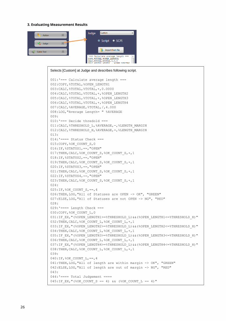
3. Evaluating Measurement Results
Selects [Custom] at Judge and describes following script.
001:'=== Calculate average length ===
002:COPY,%TOTAL,%OPEN_LENGTH1
003:CALC,%TOTAL,%TOTAL,+,0.0000
004:CALC,%TOTAL,%TOTAL,+,%OPEN_LENGTH2
005:CALC,%TOTAL,%TOTAL,+,%OPEN_LENGTH3
006:CALC,%TOTAL,%TOTAL,+,%OPEN_LENGTH4
007:CALC,%AVERAGE,%TOTAL,/,4.000
008:LOG,"Average Length= " %AVERAGE
009:
010:'=== Decide thredold ===
011:CALC,%THRESHOLD_L,%AVERAGE,-,%LENGTH_MARGIN
012:CALC,%THRESHOLD_H,%AVERAGE,+,%LENGTH_MARGIN
013:
014:'==== Status Check ===
015:COPY,%OK_COUNT_S,0
016:IF,%STATUS1,==,"OPEN"
017:THEN,CALC,%OK_COUNT_S,%OK_COUNT_S,+,1
018:IF,%STATUS2,==,"OPEN"
019:THEN,CALC,%OK_COUNT_S,%OK_COUNT_S,+,1
020:IF,%STATUS3,==,"OPEN"
021:THEN,CALC,%OK_COUNT_S,%OK_COUNT_S,+,1
022:IF,%STATUS4,==,"OPEN"
023:THEN,CALC,%OK_COUNT_S,%OK_COUNT_S,+,1
024:
025:IF,%OK_COUNT_S,==,4
026:THEN,LOG,"All of Statuses are OPEN -> OK", "GREEN"
027:ELSE,LOG,"All of Statuses are not OPEN -> NG", "RED"
028:
029:'==== Length Check ===
030:COPY,%OK_COUNT_L,0
031:IF_EX,"(%OPEN_LENGTH1>=%THRESHOLD_L)&&(%OPEN_LENGTH1<=%THRESHOLD_H)"
032:THEN,CALC,%OK_COUNT_L,%OK_COUNT_L,+,1
033:IF_EX,"(%OPEN_LENGTH2>=%THRESHOLD_L)&&(%OPEN_LENGTH2<=%THRESHOLD_H)"
034:THEN,CALC,%OK_COUNT_L,%OK_COUNT_L,+,1
035:IF_EX,"(%OPEN_LENGTH3>=%THRESHOLD_L)&&(%OPEN_LENGTH3<=%THRESHOLD_H)"
036:THEN,CALC,%OK_COUNT_L,%OK_COUNT_L,+,1
037:IF_EX,"(%OPEN_LENGTH4>=%THRESHOLD_L)&&(%OPEN_LENGTH4<=%THRESHOLD_H)"
038:THEN,CALC,%OK_COUNT_L,%OK_COUNT_L,+,1
039:
040:IF,%OK_COUNT_L,==,4
041:THEN,LOG,"All of length are within margin -> OK", "GREEN"
042:ELSE,LOG,"All of length are out of margin -> NG", "RED"
043:
044:'==== Total Judgement ====
045:IF_EX,"(%OK_COUNT_S == 4) && (%OK_COUNT_L == 4)"
045:ELSE, JUDGE_FAIL
27
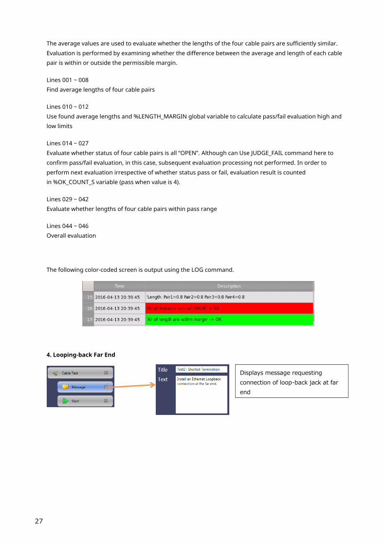
The average values are used to evaluate whether the lengths of the four cable pairs are sufficiently similar. Evaluation is performed by examining whether the difference between the average and length of each cable pair is within or outside the permissible margin.
Lines 001 ~ 008 Find average lengths of four cable pairs
Lines 010 ~ 012 Use found average lengths and %LENGTH_MARGIN global variable to calculate pass/fail evaluation high and low limits
Lines 014 ~ 027 Evaluate whether status of four cable pairs is all “OPEN”. Although can Use JUDGE_FAIL command here to confirm pass/fail evaluation, in this case, subsequent evaluation processing not performed. In order to perform next evaluation irrespective of whether status pass or fail, evaluation result is counted in %OK_COUNT_S variable (pass when value is 4).
Lines 029 ~ 042 Evaluate whether lengths of four cable pairs within pass range
Lines 044 ~ 046 Overall evaluation
The following color-coded screen is output using the LOG command.
4. Looping-back Far End
Displays message requesting
connection of loop-back jack at far
end
28
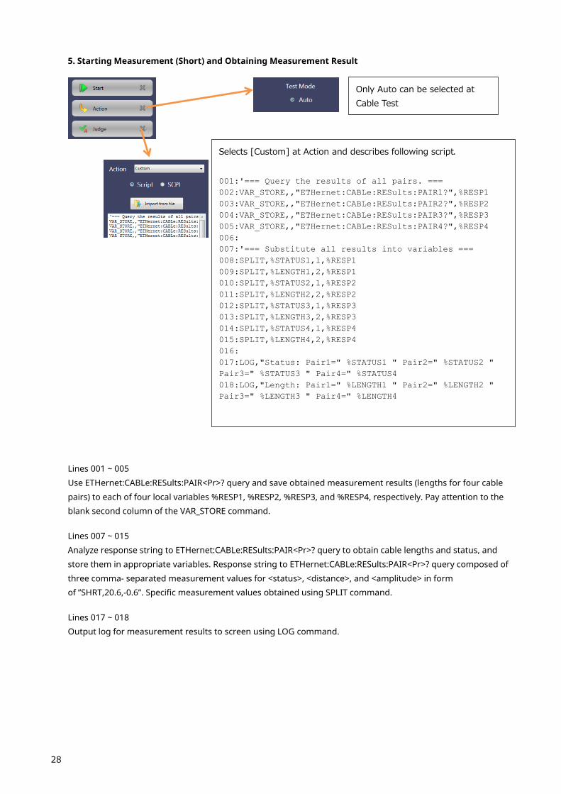
5. Starting Measurement (Short) and Obtaining Measurement Result
Lines 001 ~ 005 Use ETHernet:CABLe:RESults:PAIR<Pr>? query and save obtained measurement results (lengths for four cable pairs) to each of four local variables %RESP1, %RESP2, %RESP3, and %RESP4, respectively. Pay attention to the blank second column of the VAR_STORE command.
Lines 007 ~ 015 Analyze response string to ETHernet:CABLe:RESults:PAIR<Pr>? query to obtain cable lengths and status, and store them in appropriate variables. Response string to ETHernet:CABLe:RESults:PAIR<Pr>? query composed of three comma- separated measurement values for <status>, <distance>, and <amplitude> in form of ”SHRT,20.6,-0.6”. Specific measurement values obtained using SPLIT command.
Lines 017 ~ 018 Output log for measurement results to screen using LOG command.
Selects [Custom] at Action and describes following script.
001:'=== Query the results of all pairs. ===
002:VAR_STORE,,"ETHernet:CABLe:RESults:PAIR1?",%RESP1
003:VAR_STORE,,"ETHernet:CABLe:RESults:PAIR2?",%RESP2
004:VAR_STORE,,"ETHernet:CABLe:RESults:PAIR3?",%RESP3
005:VAR_STORE,,"ETHernet:CABLe:RESults:PAIR4?",%RESP4
006:
007:'=== Substitute all results into variables ===
008:SPLIT,%STATUS1,1,%RESP1
009:SPLIT,%LENGTH1,2,%RESP1
010:SPLIT,%STATUS2,1,%RESP2
011:SPLIT,%LENGTH2,2,%RESP2
012:SPLIT,%STATUS3,1,%RESP3
013:SPLIT,%LENGTH3,2,%RESP3
014:SPLIT,%STATUS4,1,%RESP4
015:SPLIT,%LENGTH4,2,%RESP4
016:
017:LOG,"Status: Pair1=" %STATUS1 " Pair2=" %STATUS2 "
Pair3=" %STATUS3 " Pair4=" %STATUS4
018:LOG,"Length: Pair1=" %LENGTH1 " Pair2=" %LENGTH2 "
Pair3=" %LENGTH3 " Pair4=" %LENGTH4
Only Auto can be selected at
Cable Test
29
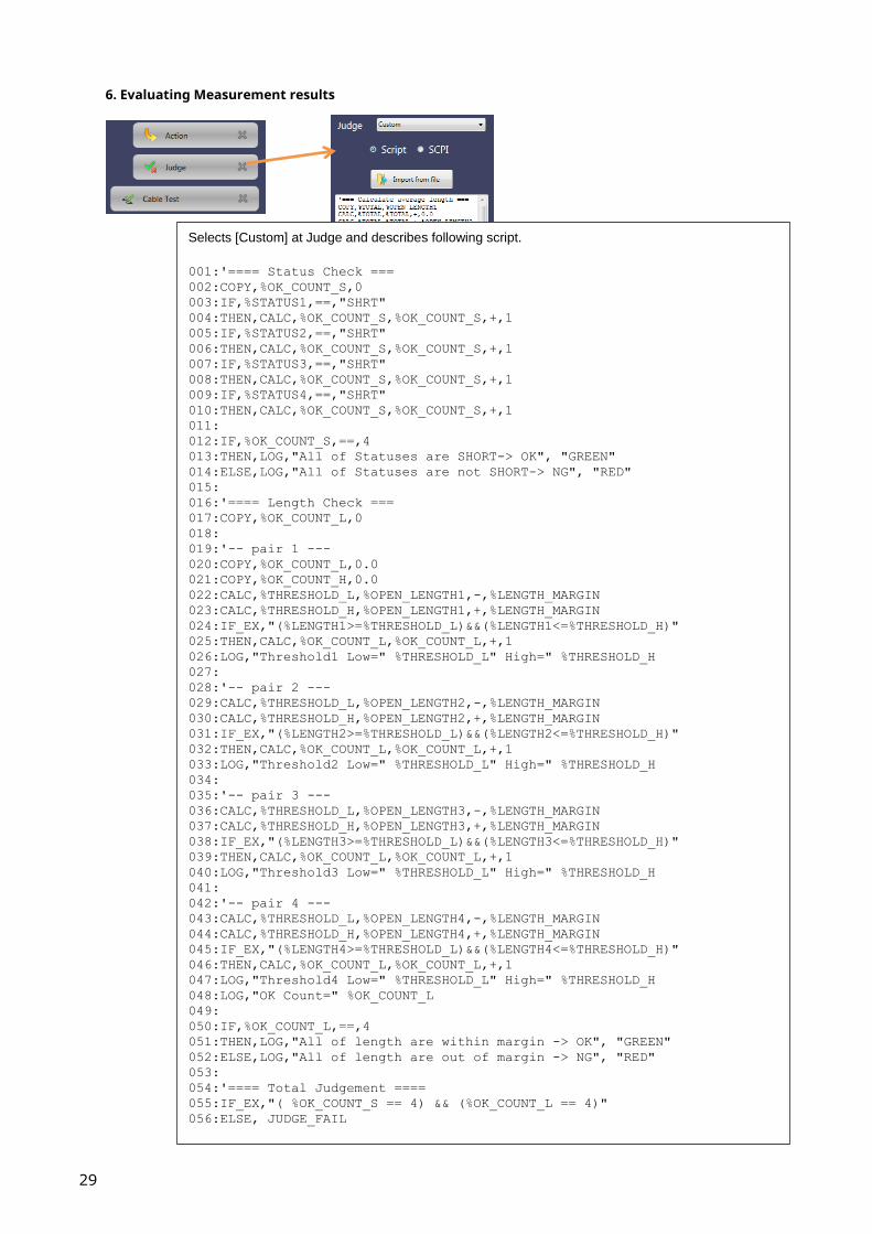
6. Evaluating Measurement results
Selects [Custom] at Judge and describes following script.
001:'==== Status Check ===
002:COPY,%OK_COUNT_S,0
003:IF,%STATUS1,==,"SHRT"
004:THEN,CALC,%OK_COUNT_S,%OK_COUNT_S,+,1
005:IF,%STATUS2,==,"SHRT"
006:THEN,CALC,%OK_COUNT_S,%OK_COUNT_S,+,1
007:IF,%STATUS3,==,"SHRT"
008:THEN,CALC,%OK_COUNT_S,%OK_COUNT_S,+,1
009:IF,%STATUS4,==,"SHRT"
010:THEN,CALC,%OK_COUNT_S,%OK_COUNT_S,+,1
011:
012:IF,%OK_COUNT_S,==,4
013:THEN,LOG,"All of Statuses are SHORT-> OK", "GREEN"
014:ELSE,LOG,"All of Statuses are not SHORT-> NG", "RED"
015:
016:'==== Length Check ===
017:COPY,%OK_COUNT_L,0
018:
019:'-- pair 1 ---
020:COPY,%OK_COUNT_L,0.0
021:COPY,%OK_COUNT_H,0.0
022:CALC,%THRESHOLD_L,%OPEN_LENGTH1,-,%LENGTH_MARGIN
023:CALC,%THRESHOLD_H,%OPEN_LENGTH1,+,%LENGTH_MARGIN
024:IF_EX,"(%LENGTH1>=%THRESHOLD_L)&&(%LENGTH1<=%THRESHOLD_H)"
025:THEN,CALC,%OK_COUNT_L,%OK_COUNT_L,+,1
026:LOG,"Threshold1 Low=" %THRESHOLD_L" High=" %THRESHOLD_H
027:
028:'-- pair 2 ---
029:CALC,%THRESHOLD_L,%OPEN_LENGTH2,-,%LENGTH_MARGIN
030:CALC,%THRESHOLD_H,%OPEN_LENGTH2,+,%LENGTH_MARGIN
031:IF_EX,"(%LENGTH2>=%THRESHOLD_L)&&(%LENGTH2<=%THRESHOLD_H)"
032:THEN,CALC,%OK_COUNT_L,%OK_COUNT_L,+,1
033:LOG,"Threshold2 Low=" %THRESHOLD_L" High=" %THRESHOLD_H
034:
035:'-- pair 3 ---
036:CALC,%THRESHOLD_L,%OPEN_LENGTH3,-,%LENGTH_MARGIN
037:CALC,%THRESHOLD_H,%OPEN_LENGTH3,+,%LENGTH_MARGIN
038:IF_EX,"(%LENGTH3>=%THRESHOLD_L)&&(%LENGTH3<=%THRESHOLD_H)"
039:THEN,CALC,%OK_COUNT_L,%OK_COUNT_L,+,1
040:LOG,"Threshold3 Low=" %THRESHOLD_L" High=" %THRESHOLD_H
041:
042:'-- pair 4 ---
043:CALC,%THRESHOLD_L,%OPEN_LENGTH4,-,%LENGTH_MARGIN
044:CALC,%THRESHOLD_H,%OPEN_LENGTH4,+,%LENGTH_MARGIN
045:IF_EX,"(%LENGTH4>=%THRESHOLD_L)&&(%LENGTH4<=%THRESHOLD_H)"
046:THEN,CALC,%OK_COUNT_L,%OK_COUNT_L,+,1
047:LOG,"Threshold4 Low=" %THRESHOLD_L" High=" %THRESHOLD_H
048:LOG,"OK Count=" %OK_COUNT_L
049:
050:IF,%OK_COUNT_L,==,4
051:THEN,LOG,"All of length are within margin -> OK", "GREEN"
052:ELSE,LOG,"All of length are out of margin -> NG", "RED"
053:
054:'==== Total Judgement ====
055:IF_EX,"( %OK_COUNT_S == 4) && (%OK_COUNT_L == 4)"
056:ELSE, JUDGE_FAIL
30
The length values recorded in the global variables as the previous measurement (open) are used to evaluate whether the lengths of the four cable pairs are sufficiently similar when the far end is shorted by the loop-back jack and when it is open. Evaluation is performed by examining whether the difference between the opened and the shorted lengths is within or outside the permissible margin.
Lines 001 ~ 014 Evaluate whether status of four cable pairs is all “SHRT”. Although can Use JUDGE_FAIL command here to confirm pass/fail evaluation, in this case, subsequent evaluation processing not performed. In order to perform next evaluation irrespective of whether status pass or fail, evaluation result is counted in %OK_COUNT_S variable (pass when value is 4).
Lines 016 ~ 052 Evaluate whether lengths of four cable pairs within pass range
Lines 054 ~ 056 Overall evaluation
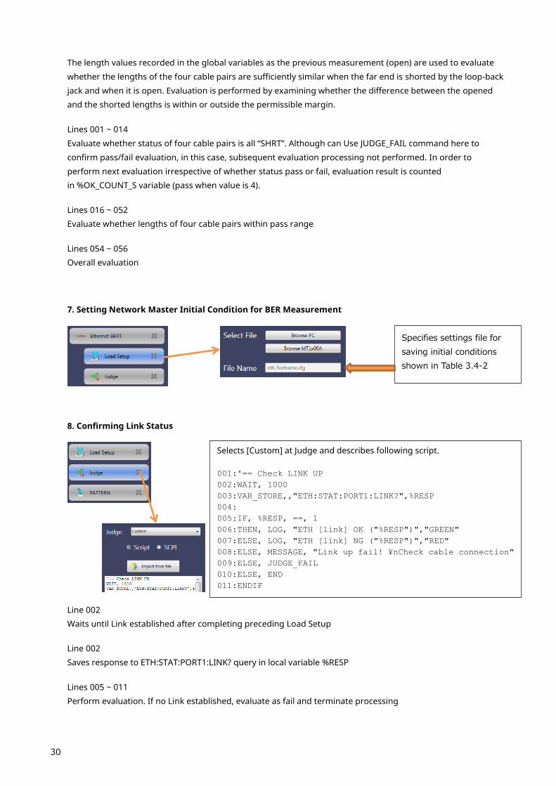
7. Setting Network Master Initial Condition for BER Measurement
8. Confirming Link Status
Line 002 Waits until Link established after completing preceding Load Setup
Line 002 Saves response to ETH:STAT:PORT1:LINK? query in local variable %RESP
Lines 005 ~ 011 Perform evaluation. If no Link established, evaluate as fail and terminate processing
Specifies settings file for
saving initial conditions
shown in Table 3.4-2
Selects [Custom] at Judge and describes following script.
001:'== Check LINK UP
002:WAIT, 1000
003:VAR_STORE,,"ETH:STAT:PORT1:LINK?",%RESP
004:
005:IF, %RESP, ==, 1
006:THEN, LOG, "ETH [link] OK ("%RESP")","GREEN"
007:ELSE, LOG, "ETH [link] NG ("%RESP")","RED"
008:ELSE, MESSAGE, "Link up fail! ¥nCheck cable connection"
009:ELSE, JUDGE_FAIL
010:ELSE, END
011:ENDIF
31
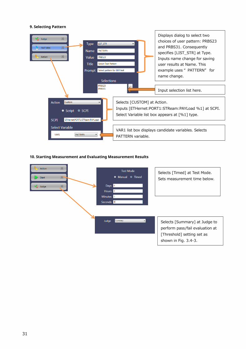
9. Selecting Pattern
10. Starting Measurement and Evaluating Measurement Results
Displays dialog to select two
choices of user pattern: PRBS23
and PRBS31. Consequently
specifies [LIST_STR] at Type.
Inputs name change for saving
user results at Name. This
example uses “ PATTERN” for
name change.
Input selection list here.
Selects [CUSTOM] at Action.
Inputs [ETHernet:PORT1:STReam:PAYLoad %1] at SCPI.
Select Variable list box appears at [%1] type.
VAR1 list box displays candidate variables. Selects
PATTERN variable.
Selects [Summary] at Judge to
perform pass/fail evaluation at
[Threshold] setting set as
shown in Fig. 3.4-3.
Selects [Timed] at Test Mode.
Sets measurement time below.

Anritsu Company 1155 East Collins Blvd., Suite 100, Richardson, TX 75081, U.S.A.Toll Free: 1-800-267-4878Phone: +1-972-644-1777Fax: +1-972-671-1877
• CanadaAnritsu Electronics Ltd.700 Silver Seven Road, Suite 120, Kanata, Ontario K2V 1C3, CanadaPhone: +1-613-591-2003 Fax: +1-613-591-1006
• Brazil Anritsu Eletronica Ltda.
Phone: +55-11-3283-2511Fax: +55-11-3288-6940
• MexicoAnritsu Company, S.A. de C.V.Av. Ejército Nacional No. 579 Piso 9, Col. Granada11520 México, D.F., MéxicoPhone: +52-55-1101-2370Fax: +52-55-5254-3147
• United KingdomAnritsu EMEA Ltd. 200 Capability Green, Luton, Bedfordshire, LU1 3LU, U.K.Phone: +44-1582-433200 Fax: +44-1582-731303
• FranceAnritsu S.A. 12 avenue du Québec, Bâtiment Iris 1- Silic 612,91140 VILLEBON SUR YVETTE, FrancePhone: +33-1-60-92-15-50Fax: +33-1-64-46-10-65
• GermanyAnritsu GmbHNemetschek Haus, Konrad-Zuse-Platz 1 81829 München, Germany Phone: +49-89-442308-0Fax: +49-89-442308-55
• ItalyAnritsu S.r.l.Via Elio Vittorini 129, 00144 Roma, ItalyPhone: +39-6-509-9711 Fax: +39-6-502-2425
• SwedenAnritsu ABKistagången 20B, 164 40 KISTA, SwedenPhone: +46-8-534-707-00Fax: +46-8-534-707-30
• FinlandAnritsu ABTeknobulevardi 3-5, FI-01530 VANTAA, FinlandPhone: +358-20-741-8100Fax: +358-20-741-8111
• DenmarkAnritsu A/SKay Fiskers Plads 9, 2300 Copenhagen S, DenmarkPhone: +45-7211-2200Fax: +45-7211-2210
• RussiaAnritsu EMEA Ltd. Representation Office in RussiaTverskaya str. 16/2, bld. 1, 7th floor.Moscow, 125009, RussiaPhone: +7-495-363-1694Fax: +7-495-935-8962
• SpainAnritsu EMEA Ltd. Representation Office in SpainEdificio Cuzco IV, Po. de la Castellana, 141, Pta. 828046, Madrid, SpainPhone: +34-915-726-761Fax: +34-915-726-621
• United Arab EmiratesAnritsu EMEA Ltd. Dubai Liaison Office
• P.R. China (Shanghai)Anritsu (China) Co., Ltd.Room 2701-2705, Tower A, New Caohejing International Business CenterNo. 391 Gui Ping Road Shanghai, 200233, P.R. ChinaPhone: +86-21-6237-0898Fax: +86-21-6237-0899
• P.R. China (Hong Kong)Anritsu Company Ltd.Unit 1006-7, 10/F., Greenfield Tower, Concordia Plaza,No. 1 Science Museum Road, Tsim Sha Tsui East, Kowloon, Hong Kong, P.R. ChinaPhone: +852-2301-4980Fax: +852-2301-3545
• JapanAnritsu Corporation
Phone: +81-46-296-6509Fax: +81-46-225-8359
8-5, Tamura-cho, Atsugi-shi, Kanagawa, 243-0016 Japan
• KoreaAnritsu Corporation, Ltd.5FL, 235 Pangyoyeok-ro, Bundang-gu, Seongnam-si, Gyeonggi-do, 13494 KoreaPhone: +82-31-696-7750Fax: +82-31-696-7751
• AustraliaAnritsu Pty. Ltd.
Phone: +61-3-9558-8177Fax: +61-3-9558-8255
• TaiwanAnritsu Company Inc.7F, No. 316, Sec. 1, NeiHu Rd., Taipei 114, TaiwanPhone: +886-2-8751-1816Fax: +886-2-8751-1817
1603
Printed on Recycled Paper
• SingaporeAnritsu Pte. Ltd.11 Chang Charn Road, #04-01, Shriro HouseSingapore 159640Phone: +65-6282-2400Fax: +65-6282-2533
• IndiaAnritsu India Private Limited2nd & 3rd Floor, #837/1, Binnamangla 1st Stage,Indiranagar, 100ft Road, Bangalore - 560038, IndiaPhone: +91-80-4058-1300Fax: +91-80-4058-1301
Specifications are subject to change without notice.
• United States
Unit 20, 21-35 Ricketts Road, Mount Waverley, Victoria 3149, Australia
902, Aurora Tower,P O Box: 500311- Dubai Internet CityDubai, United Arab EmiratesPhone: +971-4-3758479Fax: +971-4-4249036
Praça Amadeu Amaral, 27 - 1 Andar01327-010 - Bela Vista - Sao Paulo - SPBrazil
Printed in Japan 2016-5 MG No. MT1000A/MT1100A_SEEK-E-F-1-(1.00)