Embed Size (px)
Citation preview

26 InsideGNSS N O V E M B E R / D E C E M B E R 2 0 1 5 www.insidegnss.com
Precise timing lies at the heart of GNSS implementation and operation and is generally well
understood in terms of synchronizing individual satellites and/or receivers. Recent results, however, have demon-strated that timing of code and phase measurements in a receiver can have significant implications for the timing community in particular.
Specifically, papers presented to the 2015 joint meeting of the International Frequency Control Symposium and the European Forum on Time and Fre-quency (see Further Reading section for details) demonstrated that a one-microsecond delay between the times of code measurements and of phase measurements will appear as a 30 pico-second/day drift in the clock solution based on the analysis of these code and phase measurements. This explained observations that for certain geodetic receivers a frequency bias seemed to exist between code and phase clock at the level of 100s of picoseconds per day.
The ProblemPrecise point positioning (PPP) is often used for remote atomic clock com-parisons, as well as for the generation of coordinated universal time (UTC). PPP determines the difference between the GNSS receiver’s clock frequency and time and a reference time scale by modeling code and carrier phase mea-surements using externally provided satellite clock and orbit products.
The difference between the PPP clock solutions of two stations yields the difference between their two clocks. The average of the clock differ-ences is determined by the code mea-surements, because only the code data
are unambiguous. The clock frequency solution (shape/derivative of the time curve) is derived from the carrier phase data because, although ambiguous by an integer number of wavelengths, they are about 100 times more precise than the code data.
The high timing precision of PPP, at the level of tens of picoseconds over averaging times from a few minutes to a few hours, can unfortunately be marred by noticeable receiver-based frequency offsets. Figure 1 shows an example of this, corresponding to the difference between two daily PPP clock solutions of two receivers con-nected to a common clock and com-mon antenna. We would expect the differences to be zero, with white noise superimposed, and in fact the averages over a day are nearly zero. However, a sawtooth pattern also appears that repeats each day.
We will show that this sawtooth pattern is due to the satellite motion during a microsecond-level difference between the latching times (effectively the measurement times) for the code measurements and the phase mea-surements in one of the two receivers. Because the receivers report these as simultaneous observations, the effect is to add a systematic frequency offset to the phase data.
Figure 2 shows the between-receiver difference of the slopes of a linear fit on the ionosphere-free linear phase com-bination over each complete satellite track (i.e., from when a satellite rises above the horizon until it sets below it), and the non-zero values show that the frequency offset is present during each track. The slope difference of 200 pico-seconds/day was strongly reduced after
GNSS Solutions is a regular column featuring questions and answers about technical aspects of GNSS. Readers are invited to send their questions to the columnist, Dr. Mark Petovello, Department of Geomatics Engineering, University of Calgary, who will find experts to answer them. His e-mail address can be found with his biography below.
GNSS SOLUTIONS
MARK PETOVELLO is a Professor in the Department of Geomatics Engineering at the University of Calgary. He has been actively involved in many aspects of
positioning and navigation since 1997 including GNSS algorithm development, inertial navigation, sensor integration, and software development. Email: [email protected]
How Important Is It to Synchronize the Code and Phase Measurements of a GNSS Receiver?

www.insidegnss.com N O V E M B E R / D E C E M B E R 2 0 1 5 InsideGNSS 27
MJD 56015, coincident with a firmware change that reduced the latching offset between the code and phase measurements by five microseconds.
To explain why having the same latching time is impor-tant, we start with the fact that only the unambiguous code measurements can be used to determine the actual emission time of the signals; therefore, the phase data will use a code-determined satellite position in the modeling, based on the code data latching time instead of the phase latching time. Neglecting all satellite-based and propagation error sources, the code and carrier phase measurements are essentially the sum of the geometric range from the antenna to the satellite and the receiver clock bias multiplied by the speed of light.
Consider two receivers connected to the same frequency reference and the same antenna that take their measurements with a short time offset of Δt. The receivers’ code and carrier phase measurements will differ by a term due to a clock bias difference (c.Δt) and a term that accounts for the fact that the satellite has moved during the short interval Δt and that its geometric range has changed as a result. The rate of change of the geometric range is equal to the satellite Doppler in hertz multiplied by the carrier wavelength.
The differences in code and phase measurements of two co-located receivers r1 and r2, driven by a same frequency but de-synchronized by an offset Δt, can therefore be expressed as:
where the term A accounts for the carrier phase ambiguities. Let us consider as an example two receivers using the
same atomic clock frequency, but offset in time by 201 micro-seconds. Figure 3 presents the differences between the code and phase measurements for several satellite tracks, as well as the theoretical value from Equation (1). In the carrier phase differences, the ambigu-ity over each track was removed, so that all the tracks have an average of zero.
Let us now consider a single receiver in which the phase measurements are made after the code measurements with delay τ. To fully remove ionospheric effects, we work with the dual-frequency ionosphere-free combination of codes (P3) and phases (L3). In this case, the differences between the code and carrier phase data will contain a satellite-independent constant clock-bias and a satellite-dependent term corresponding to the integrated Doppler frequency over the interval τ. Specifically, the difference between code and phase measurements at the time t for a satellite, in cycles, is given by:
where A(sat) is the ambiguity and w(t,sat) is the carrier phase windup. (More information on carrier phase windup is avail-able in Sunil Bisnath’s GNSS Solutions article in the July/August 2007 issue or in the Additional Resources section near the end of this article.)
The correction associated to the latching offset (or bias) Δ(t,sat) is what needs to be applied in a PPP analysis. It is unfortunately never applied in normal receiver operation, and for most receivers the value of the latching offset is not even known to the users. Note also that only the second
FIGURE 1 PPP-measured timing difference between GPS receivers with common antenna and clock, using daily solutions. This frequency difference became much less after one of the units received a firmware change.
Receiver X - Receiver Y, Common Clock, Common Antenna
0.10
0.05
0
–0.05
–0.10
Nan
osec
onds
Modi�ed Julian Day55966 55968 55970 5597255967 55969 55971 55973
FIGURE 2 Fitted slopes, in nanoseconds/day, of individual completed satellite tracks. Data from the two frequencies were first combined into the ionosphere-free combination.
Slope of Satellite Tracks of Receiver X - Receiver Y in L3, from RINEX �les0.5
0.4
0.3
0.2
0.1
0.0
–0.1
–0.2
–0.3
ns/d
ay (e
ach
poin
t is
slope
ov
er s
atel
lite
trac
k)
Modi�ed Julian Day55940 55980 56020 56060 56100 56140


30 InsideGNSS N O V E M B E R / D E C E M B E R 2 0 1 5 www.insidegnss.com
term of Δ(t,sat) is relevant as the first term is constant and absorbed by the carrier ambiguity estimate.
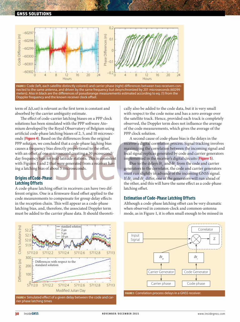
The effect of code-carrier latching biases on a PPP clock solutions has been simulated with the PPP software Ato-mium developed by the Royal Observatory of Belgium using artificial code-phase latching biases of 2, 5, and 10 microsec-onds (Figure 4). Based on the differences from the original PPP solution, we concluded that a code-phase latching bias causes a frequency bias directly proportional to the offset, with an offset of one microsecond creating a 30 picosecond/day frequency bias for mid-latitude stations. This is consistent with Figures 1 and 2 that were generated from a receiver hav-ing a latching bias of about 5 microseconds.
Origins of Code-Phase Latching OffsetsA code-phase latching offset in receivers can have two dif-ferent origins. One is a firmware-fixed offset applied to the code measurements to compensate for group delay effects in the reception chain. This will appear as a code-phase latching bias, and, therefore, the associated Doppler term must be added to the carrier phase data. It should theoreti-
cally also be added to the code data, but it is very small with respect to the code noise and has a zero average over the satellite track. Hence, provided each track is completely observed, the Doppler term does not influence the average of the code measurements, which gives the average of the PPP clock solution.
A second cause of code-phase bias is the delays in the receiver’s digital correlation process. Signal tracking involves maximizing the correlation between the incoming signal and local signal replicas generated by code and carrier generators implemented in the receiver’s digital circuits (Figure 5).
Due to the delays δtC and δtφ from the code and carrier generators to the correlator, the code and carrier generators must run slightly in advance of the incoming GNSS signal. If δtC and δtφ differ, one of the generators will run ahead of the other, and this will have the same effect as a code-phase latching offset.
Estimation of Code-Phase Latching OffsetsAlthough a code-phase latching offset can be very dramatic when observed in common-clock and common-antenna mode, as in Figure 1, it is often small enough to be missed in
GNSS SOLUTIONS
FIGURE 3 Code (left, each satellite distinctly colored) and carrier phase (right) differences between two receivers con-nected to the same antenna, and driven by the same frequency but desynchronized by 201 microseconds (60299 meters). Also in black are the differences of pseudorange measurements estimated according to eq. (1) from the Doppler frequency and the known receiver clock offset.
–60297
–60298
–60299
–60300
–60301
–60302
Code
Di�
eren
ces (
m)
Hours0 4 8 12 16 20 24
0.2
0.1
0
–0.1
–0.2
Phas
e D
i�er
ence
s (m
)
Hours0 4 8 12 16 20 24
FIGURE 4 Simulated effect of a given delay between the code and car-rier phase latching times
52.252.152.051.9
Cloc
k So
lutio
ns (n
s)
Modied Julian Day
57112.0 57112.2 57112.4 57112.6 57112.8 57113
standard solution2 μs5 μs10 μs
Di�erences with respect to the standard solution
300
200
100
0Di�
eren
ces (
ps)
57112.0 57112.2 57112.4 57112.6 57112.8 57113
FIGURE 5 Correlation process delays in a GNSS receiver.
InputSignal
δtφ δtc
Σ
Carrier Generator
Carrier phase
Code Generator
Correlator
Code phase

www.insidegnss.com N O V E M B E R / D E C E M B E R 2 0 1 5 InsideGNSS 31
the timing data of isolated receivers. Non-recognition of the problem would result in a mis-measurement of the frequency difference between precise clocks, such as masers, atomic fountains, or optical clocks.
Instead, differencing the code data residuals from the phase residuals removes the effects of the reference time scale and all effects common to both the phase and code. This leaves the second-order ionosphere effect, the ambiguities, and the latching bias. The second-order ionosphere effect is below the 10-picosecond level and thus insignificant, and the ambiguities are estimated explicitly.
We then computed the slope of code-minus-phase residu-als — which represents the frequency bias and, in turn, the latching bias — for each satellite track, and the average slope was estimated over different batch lengths. Note that errors in estimating ambiguities can affect the frequency determi-nation quantitatively, depending upon the relative code and phase weights (during PPP processing).
The approach that we have described here requires very long data sets in order to estimate the frequency bias with sufficient precision. The effect is readily observed over peri-ods of a few days or less, but monthly solutions require reduc-ing the code’s weight to reveal the effect.
Figure 6 shows the estimated frequency biases from the monthly PPP solutions of October, November, and December 2014, for all seven types of receivers that contributed data to the BIPM (Bureau International des Poids et Mesures).
To generate these results, the code was down-weighted by 10 billion. The formal errors in the slope determinations are about 4.4 picoseconds/day, or about the size of the circles in the plot. The fact that the points differ for the various months can be explained largely by differences in the ambiguity deter-mination.
We can see that the non-zero mean slope of the code-minus-phase residuals is widespread among receiver types. However, it should be possible to design receivers with mini-
FIGURE 6 Frequency bias, in nanoseconds/day for all receiver types (numbered 1-7) that contributed to BIPM for October, November and December 2014.
Slope of Residuals, IGS Finals, Code Downweighted by 1.E100.2
0.1
0.0
–0.1
–0.2
–0.3
ns/d
ay
Receivers by Type1 2 3 4 5 6 7
M1 M2 M3 M4 M5 M6 M7
A miniature IMUWeight: 0,12 lbs (55g) Volume: 2,0 cu. in. (35cm3)
[email protected] • www.sensonor.com
When size, performance and robustness matter
Available now – contact us to discuss your application
Certain missions demand unsurpassed precision, stability and reliability. Having perfect control and fully understanding the smallest detail is what it takes to be a world leader.
With this in mind, we developed the Inertial Measurement Unit STIM300, a small, utra-high performance, non-GPS aided IMU:
• ITAR free• Small size, low weight and low cost• Insensitive to magnetic fi elds• Low gyro bias instability (0.5°/h)• Low gyro noise (0.15°/√h)• Excellent accelerometer bias instability (0.05mg)• 3 inclinometers for accurate leveling
STIM300 is the smallest and highest performing, commercially available IMU in its category, worldwide!
… TO BE EVEN BETTER!
Phot
o: S
indr
e Lu
ndvo
ld

32 InsideGNSS N O V E M B E R / D E C E M B E R 2 0 1 5 www.insidegnss.com
GNSS SOLUTIONS
mal difference between the code and phase latching times.
OutcomeIn September 2015, in view of these considerations, the Consultative Com-mittee on Time and Frequency passed a resolution calling upon manufactur-ers of geodetic receivers to reduce their latching time biases to less than 100 nanoseconds, after due allowance is made for all receiver hardware, soft-ware, and firmware delays.
The sidebar, “CCTF Recommenda-tion on GNSS Receiver Design,” sug-gests a change that could improve the performance of receivers for time and frequency applications.
ManufacturersThe receivers that provided data to the BIPM as shown in Figure 6 include the following: Ashtech Z-XII3T, for-merly Ashtech now a part of Trimble Integrated Technologies, Sunnyvale,
California USA; GTR50 from DICOM spol. s r.o., Uherské Hradiště, Czech Republic; the JPS Eurocard from Javad Positioning Systems, now part of Topcon Positioning Systems, Inc., Livermore, California USA; JAVAD E_GGD and JAVAD TRE_G3T from JAVAD GNSS, San Jose, California USA, and Moscow, Russian Federa-tion; OEM4-G2, OEM638, OEM638, OEMV3, and OEMV3G receivers from NovAtel, Inc., Calgary, Alberta, Canada; PolaRx2, PolaRx3ETR, and PolaRx4TR receivers from Septentrio, Leuven, Belgium; and TTS-4 receiv-ers from Piktime Systems, Poznań, Poland.
Further ReadingFor information on about the link between code-phase latching offset on frequency bias, refer to the following:[1] Defraigne, P., and J-M. Sleewaegen, “Cor-rection for Code-Phase Clock Bias in PPP”, Proceedings Joint Meeting of the International
Frequency Control Symposium and European Forum on Time and Frequency, Denver, Colo-rado USA, 2015
[2] Matsakis, D., Z. Jiang and W. Wu, 2015, “Car-rier Phase Biases in Receivers Used for UTC Generation”, Proceedings Joint Meeting of the International Frequency Control Symposium and European Forum on Time and Frequency, Denver, Colorado USA, 2015
[3] Matsakis, D., and Z. Jiang and W. Wu, “Carrier Phase Biases in Receivers Used for UTC Genera-tion,” Proceedings Institute of Navigation Pacific PNT Meeting, Honolulu, Hawaii USA, 2015
[4] Weiss, M. A., and J. Yao and Y. Li, 2013, “In Search of a New Primary GPS Receiver for NIST” in Proceedings of the 44th Annual Precise Time and Time Interval (PTTI) Systems and Applications Meeting, Reston, Virginia USA, December 2012
For information on phase windup and second-order ionosphere effects, refer to the following:[5] Pireaux, S., and P. Defraigne, L. Wauters, N. Bergeot, Q. Baire, C. Bruyninx, “Higher-Order Ionospheric Effects in GPS Time and Frequency Transfer,” GPS Solutions, 14(3), 267-277, 2010
[6] Wu, J., and S. Wu, G. Jahh, W. Bertiguer, and S. Litchen, “Effects of Antenna Orientation on GPS Carrier Phase Measurements,” Manuscripta geodaetica, 18, pp. 91-98, 1993
AuthorsPascale Defraigne received her Ph.D. in physics at the Uni-versité Catholique de Louvain (UCL), Belgium. She is now head of the Time Laboratory at
the Royal Observatory of Belgium. She current-ly chairs the working group on GNSS Time Transfer of the Consultative Committee of Time and Frequency.
Jean-Marie Sleewaegen is cur-rently responsible for the GNSS signal processing, system architecture, and technology development at Septentrio
Satellite Navigation in Leuven, Belgium. He received his M.Sc. and Ph.D. in electrical engi-neering from the University of Brussels. He received the Institute of Navigation (ION) Burka award in 1999.
Demetrios Matsakis is chief scientist for Time Services at the U.S. Naval Observatory (USNO). He has worked on most aspects of timekeeping,
and served as head of the USNO’s Time Service Department for 17 years. He received his Ph.D. in physics from the University of California at Berkeley.
CCTF Recommendation on GNSS Receiver DesignThe following 2015 Recommendation from the Consultative Committee for Time and Frequency addresses suggested modifications in the design of GNSS receivers used for timing applications:Considering that
• TheuseofacombinationofcodeandcarrierphaseGNSSmeasurementsenables time and frequency transfer with sub-nanosecond precision,
• ThistechniqueisroutinelyusedforUTCgeneration,• GNSSmeasurementsareexpectedtobeusedbyagreaternumberof
applications that require greater precision, such as the comparison of optical frequency standards and atomic fountains,
• TheprecisionoftheGNSStimeandfrequencytransfersolutionreliesontheaccurate knowledge of the lathing time (effective reception times) of each measurement;
noting that• whileconsideredassynchronous,thelatchingtimesofphaseandcodedata
can be systematically offset by several microseconds,• somereceiverproducecodemeasurementscorrectedforaconstantbiasto
account for internal hardware delays, inducing an apparent latching time offset between the code and carrier phase measurements,
• thedifferencebetweenthelatchingtimesofcodeandphaseinducesaDopplerincrement in the carrier phase measurements relative to the codes, causing a frequency bias in the phase data and hence in the clock solution obtained from GNSS analysis,
• thisfrequencybiasresultsinalaboratoryclock’sfrequencyappearingtobebiased by 30 ps/day for every microsecond of latching offset;
recommends that• Manufacturersdesignfuturereceiversandfirmwareupgradessothatthe
absolute value of the latching time offset between code and carrier phase measurements provided in the observation files is less than 100 ns, taking into account all relevant receiver internal delays, and include this information in the receiver specifications.

GPS Networking, Inc. has specialized for 20 years, in providing global positioning products and solutions to enable you to e�ectively distribute the GPS/GNSS signal throughout your facility. We have customized solutions for providing the GPS/GNSS equipment for virtually every type of environment and applica-tion. GPS Networking solutions include GPS/GNSS DAS networks throughout the Major wireless carriers locations including base station applications, integral in the wireless rollout. We also have designed and developed networks which include re-radiating GPS/GNSS in Military Vehicles and countless defense applications. If you need information on how to accomplish your particular GPS/GNSS Network objective, please call us at 1-800-463-3063 and let us put our skills and experience to work for you.
All units are built for your speci�c application!
373 E. Industrial Blvd., Pueblo West, CO 81007 800-463-3063 www.gpsnetworking.com
Fiber Optic Antenna Link Antenna Splitters – 2 – 32 Ports Re-Radiating/Re-Broadcasting KitsLine Ampli�ers
MilitaryGovernment
First Responders
DAS/Wireless
Survey & Mapping
Test & Measurement
• RELIABLE: Experience Matters• ACCURATE: Trust is built on it• AVAILABLE: Timing and Synchronization• CUSTOM: Built for your need