Embed Size (px)
Citation preview

April 30, 2004 Yu Hen Hu
Page 1 of 12
Department of Electrical and Computer Engineering University of Wisconsin – Madison
ECE 734 VLSI Array Structures for Digital Signal Processing Spring 2004
Homework #4 Solution
This homework consists of questions taken from the notes and open-ended questions. You must do the homework by yourself. No collaborations are allowed. There are total 100 points. This homework is worth 10% of your overall grades. 1. (5 points) Unfold the DFG in figure 5.20 using unfolding factor 3 (problem 1, chapter 5) 2. (5 points) Prove the relationship in (5.3) used to show that unfolding preserves the number of
delays. (problem 3, chapter 5) 1 1w w w J
wJ J J
+ + − + + + = L
3. (5 points) Prove that the critical path of a J-unfolded DFG is greater than or equal to the critical path of the (J−1)-unfolded DFG (problem 5, chapter 5)
4. (5 points) Problem 7, Chapter 5 textbook, pp. 142. 5. (5 points) Problem 8, Chapter 5 textbook, pp. 143. 6. (5 points) Problem 10, Chapter 5 textbook, pp. 143. 7. (5 points) Problem 13, Chapter 5 textbook, pp. 144. 8. (10 points) Problem 16, Chapter 5 textbook, pp. 144. 9. (10 points) Problem 17, Chapter 5 textbook, pp. 145. Read chapters 1 to 3 of TMS320C6000 CPU and Instruction Set Reference Guide that is posted on the course homepage. Then answer the following questions. You may skip any C64-specific information or floating-point arithmetic related information. 10. (5 points) What is a timer? List at least three different usages of the two on-chip 32-bit timer.
Answer: A timer is a programmable counter that can be programmed to provide (a) timing events, (b) count events, (c) generate pulses or square waves, (d) interrupt CPU, and (e) send synchronization events to DMA/EDMA controller
11. (15 points) Consider the following assembly code (page 3-41 of the manual) Memory address (hex) Instruction
0000 0000 B .S1 LOOP 0000 0004 ADD .L1 A1, A2, A3 0000 0008 || ADD .L2 B1, B2, B3 0000 000C LOOP: MPY .M1X A3, B3, A4 0000 0010 || SUB .D1 A5, A6, A6 0000 0014 MPY .M1 A3, A6, A5 0000 0018 MPY .M1 A6, A7, A8 0000 001C SHR .S1 A4, 15, A4 0000 0020 ADD .D1 A4, A6, A4
(a) (5 points) Give the 32-bit opcode of the instruction B .S1 LOOP
Assume that this “branch using a displacement” instruction is the first instruction in an instruction packet.
April 30, 2004 Yu Hen Hu
Page 2 of 12
Answer: Note the formula: cst = (label − PCE1) >>2. Now, label = 0000 000C h, PCE1 = 0000 0000 h (since B .S1 LOOP is the first instruction in the instruction packet). So, cst = (0000 000C − 0000 0000) >> 2 h = 0000 0003 h
0
0 0 0 0 0 0 0 0 0 0 0 0 0 0 0 0 0 0 0 0 0 0 1 1 0 0 1 0 0 0 0
creg z cst z p
(b) (5 points) specify the parallel bit (bit 0 of each instruction) of the current instruction packet. Answer: 0 1 0 1 0 0 0 0
(c) (5 points) Explain why the instructions SUB .D1 … and the following one MPY .M1 … can not be executed in parallel? Can you fix it so that they can be executed in parallel? Are there other instructions that should have been executed in parallel within this instruction packet? If so, what are they? Answer: there is a true data dependence on A6. Hence there is NO way to make these two instructions to be executed in parallel. On the other hand, the instructions MPY .M1 A6, A7, A8 and SHR .S1 A4, 15, A4 can be executed in parallel because there are no resource conflict between them. The last two instruction SHR and ADD can NOT be executed in parallel due to data dependence of A4
12. (10 points) DCT implementation Consider DCT for JPEG/MPEG image compression applications. Two dimensional, separable DCTs are applied to each 8 by 8 block of image f(m,n), 0 ≤ m,n ≤ 7 where −128 ≤ f(m,n) ≤ 127 is the value (8-bit 2’s complement integers) of the (m,n) pixel after level shift by subtracting 128 from each pixel’s value. The 2D DCT coefficients are denoted by F(u,v), 0 ≤ u, v ≤ 7. A fast 1D 8-point DCT algorithm by Arai, Agui, and Nakajimi is give below. You may download the MATLAB m-file fastdct.m from course web page to experiment it yourself. For convenience, the algorithm is listed below where the constant multipliers a1 to a5 are represented by 16-bit fixed point 2’s complement numbers with 8 fractional binary digits.
Input: x(m), m = 0 to 7. % a1=0.707, a2=0.541, a3=0.707, a4=1.307, a5=0.383 % scaled values of multipliers (multiplied by 128) in hexadecimal % a1=a3=005Ah, a2= 0045h, a4=00A7h, a5=0031h % step 1 % x(m,1) = x(m) + x(7-m), m = 0, 1, 2, 3 % x(m,1) = x(7-m) - x(m), m = 4, 5, 6, 7 %Step 2. % x(m,2) = x(m,1) + x(3-m,1), m = 0, 1 % x(m,2) = x(3-m,1) - x(m,1), m = 2, 3 % x(4,2) = -x(4,1) - x(5,1) % x(m,2) = x(m,1) + x(m+1,1), m = 5, 6 % x(7,2) = x(7,1) % Step 3. % x(0,3) = x(0,2) + x(1,2) % x(1,3) = x(0,2) - x(1,2) % x(2,3) = x(2,2) + x(3,2) % x(4,3) = x(4,2) + x(6,2) % x(m,3) = x(m,2), m = 3, 5, 6, 7
April 30, 2004 Yu Hen Hu
Page 3 of 12
% Step 4. % x(m,4) = x(m,3), m = 0, 1, 3, 7 % x(2,4) = x(2,3)*a1 % tmp = x(4,3) * a5 % x(4,4) = x(4,3)*a2 + tmp % x(5,4) = x(5,3)*a3 % x(6,4) = x(6,3)*a4 + tmp % Step 5. % x(m,5) = x(m,4), m = 0, 1, 4, 6 % x(2,5) = x(2,4) + x(3,4) % x(3,5) = x(3,4) - x(2,4) % x(5,5) = x(7,4) + x(5,4) % x(7,5) = x(7,4) + x(5,4) % Step 6. % x(m,6) = x(m,5), m = 0, 1, 2, 3 % x(4,6) = x(4,5) + x(7,5) % x(5,6) = x(5,5) + x(6,5) % x(6,6) = x(5,5) - x(6,5) % x(7,6) = x(7,5) + x(4,5) output: y(m) = x(m,6), m = 0 to 7
We will consider a dedicated hardware implementation of this algorithm. We will use four types of components: (i) hardware multiplier, M; (ii) hardware adder, A; (iii) dedicated buses, B, and (iv) registers R. We assume the eight 8-bit inputs can be made available simultaneously if needed from input ports. The outputs will be stored in eight output registers. The output will not be made available to outside this hardware DCT module until all eight outputs are ready. (a) (5 points) If we want to avoid any truncation error due to finite register length, in the
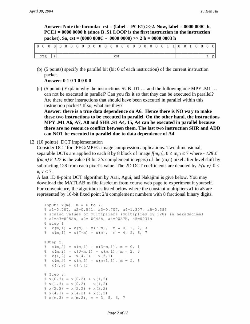
worst case, how many bits, as a function of n, will be required to store each intermediate or final result without incurring any rounding error or overflow? For convenience, you may assume n = 8. Hint: To do this part, you may scale the five constant multipliers a1 to a5 by 256 so that they are all represented with 16-bit integers. Note that their values are known. For example, the result of the multiplication of an m-bit integer x to the scaled (by 128) value of a3 will result in no more than m+7 significant bits. Answer: addition of 2m numbers will increase dynamic range by at most m-bits. Multiplication of a m-bit number with an n-bit number will result in at most (m+n)-bit result. We assume {x(i)} and cosine functions are all represented with n-bit signed binary numbers. The dynamic range can be recorded using the following table (assume n = 8)
k\m 1 2 3 4 5 y(k) 0 9 10 11 11 1 9 10 11 11 2 9 10 10 18 19 19 3 9 10 10 19 19 4 9 10 11 19 19 20 5 9 10 10 17 18 20 6 9 10 10 19 19 20 7 9 9 9 19 20 tmp 18
April 30, 2004 Yu Hen Hu
Page 4 of 12
Clearly at most 20 bits will be needed to store the final results without any error. (b) (5 points, CC) If the resulting DCT coefficients are to be rounded to nearest integers, how
many bits are required to represent the results? Answer: 20 − 7 = 13 bits. In the standard, only 12 bits are used since it is almost impossible to find a set of coefficients that produce a result that needs 20 bits to represent without error.
13. (15 points) CORDIC In the CORDIC algorithm, we define
[ ]
−=→
+===
−−−
−
−−
−−
rotation. hyperbolic rotation; linear
rotation; circular
,12tanh,02,12tan
2tan1
)(),1(1
),0(
),1(1
),(1
mmm
mm
iais
is
is
imsm
(a) (5 points) Prove that [ ] ),0(),(1
0022tan
1lim)(lim isims
mm
mm
mia −−−
→→==
Answer:
( )
[ ] ),0(),(1
0
),0(
220
1
0
1
0
22tan1
lim)(,2,
.1
1lim
//tan
limtan
lim
isims
mmis
xxx
mm
iacmx
cxc
cdxdx
dxcxdx
cx
−−−
→
−
→
−
→
−
→
====
=
+⋅==
then Let
(b) (5 points) Prove that ),1(11 2tanh)( isia −−−
− =
Answer: Let j = 1− . Then,
( )( ) ( )
( ) ( )( ) ( )
( ),sinh22
sin,cosh22
cos xjjee
jee
jxxeeee
jxxxjxjjxjxxjxjjxj
=−
=−
==+
=+
=−−−−
Hence, ( ) )tanh(tan xjjx = . For m = −1, ( ) ( ) ),1(11 21)(tanh)(1tan isiajia −−
−− −==− . Therefore, ),1(1
1 2tanh)( isia −−−− = .
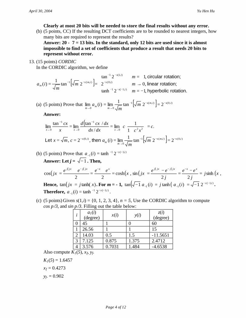
(c) (5 points) Given s(1,i) = {0, 1, 2, 3, 4}, n = 5, Use the CORDIC algorithm to compute cos π/3, and sin π/3. Filling out the table below:
i a1(i) (degree) x(i) y(i) z(i)
(degree) 0 45 1 0 60 1 26.56 1 1 15 2 14.03 0.5 1.5 -11.5651 3 7.125 0.875 1.375 2.4712 4 3.576 0.7031 1.484 -4.6538
Also compute K1(5), xf, yf.
K1(5) = 1.6457
xf = 0.4273
yf. = 0.902
April 30, 2004 Yu Hen Hu
Page 5 of 12
Solution for the problem from chapter5 of the text book
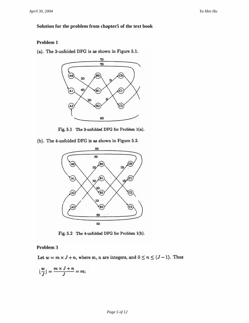
Problem 1
Problem 3
April 30, 2004 Yu Hen Hu
Page 6 of 12
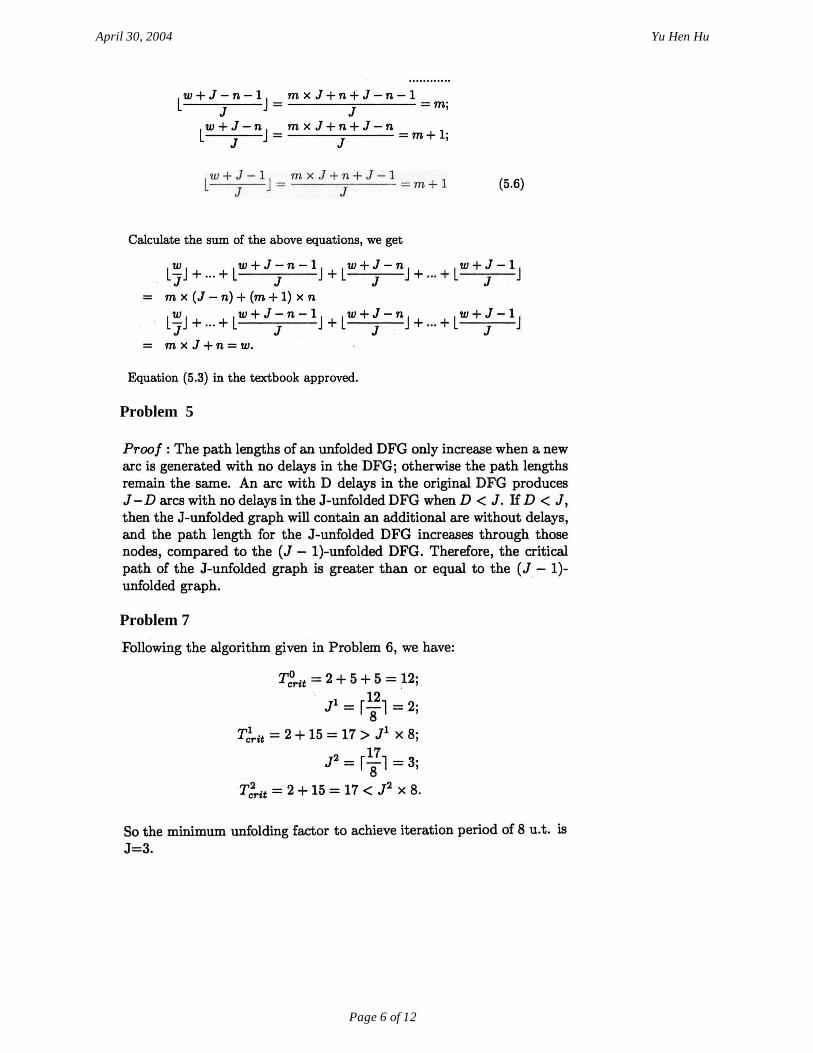
Problem 5
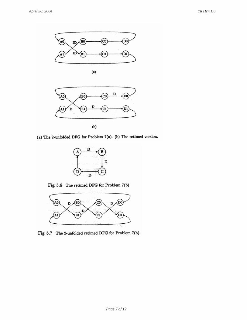
Problem 7
April 30, 2004 Yu Hen Hu
Page 7 of 12
April 30, 2004 Yu Hen Hu
Page 8 of 12
Problem 8
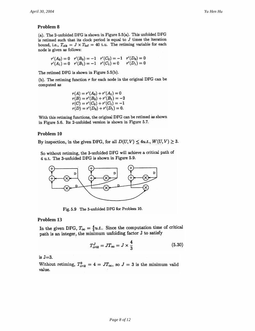
Problem 10
Problem 13
April 30, 2004 Yu Hen Hu
Page 9 of 12
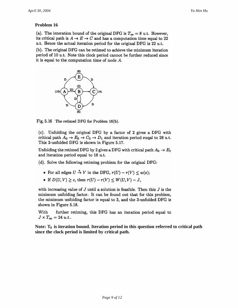
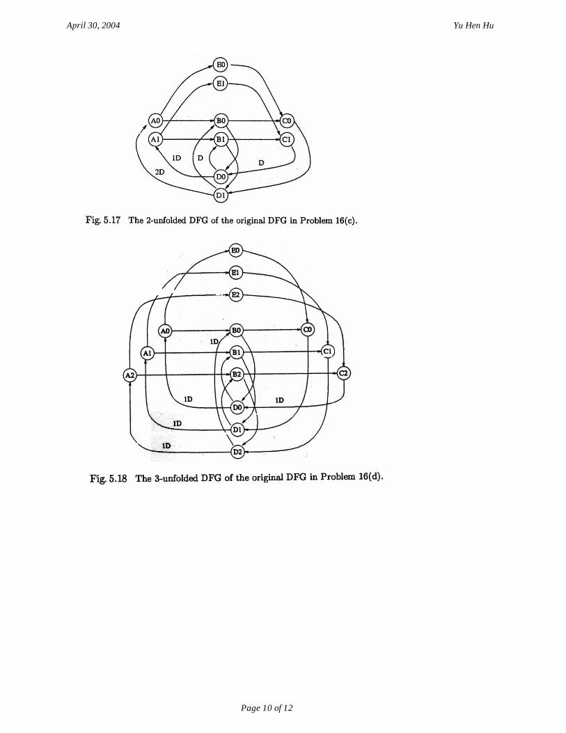
Problem 16
Note: T8 is iteration bound. Iteration period in this question referred to critical path since the clock period is limited by critical path.
April 30, 2004 Yu Hen Hu
Page 10 of 12

April 30, 2004 Yu Hen Hu
Page 11 of 12
Problem 17

April 30, 2004 Yu Hen Hu
Page 12 of 12


![Homework #2 Solution - University of …homepages.cae.wisc.edu/~ece734/homework/s04/hw2s04sol.pdfMarch 24, 2004 Yu Hen Hu Page 3 of 14 8. (4 points) Text book [Parhi], Chapter 3, problem](https://img.pdfslide.us/doc/110x75/5acb65997f8b9a63398ba9f7/homework-2-solution-university-of-ece734homeworks04hw2s04solpdfmarch.jpg)