Embed Size (px)
Citation preview
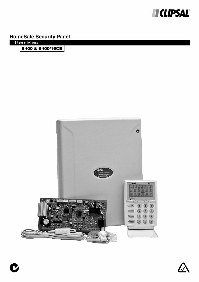
5400 & 5400/16CB
HomeSafe Security PanelUser's Manual
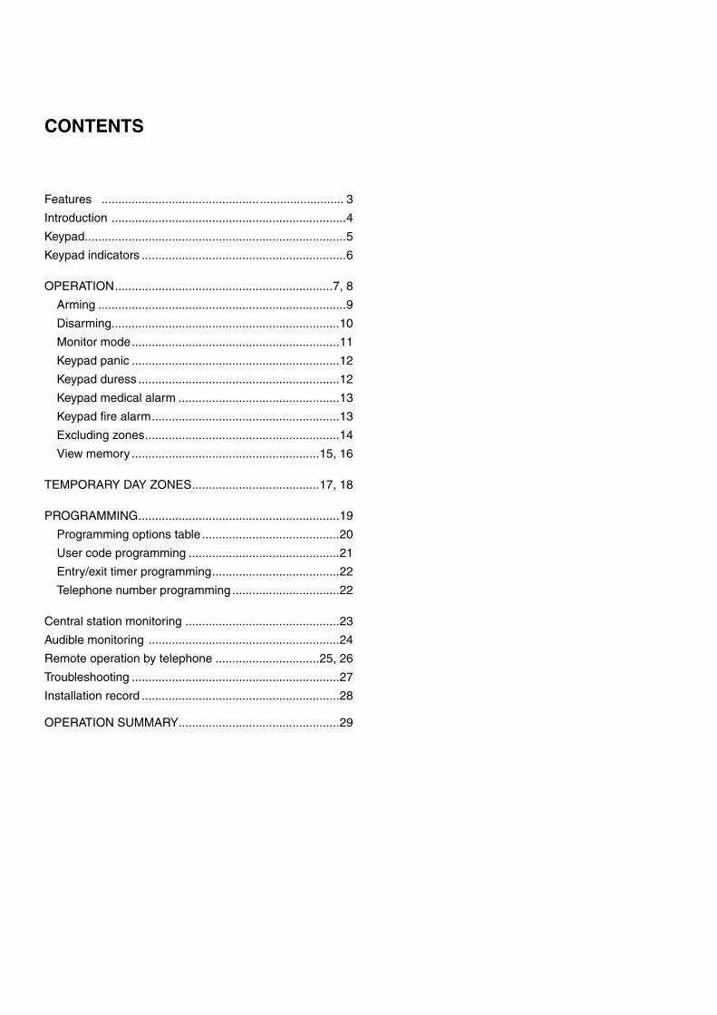
CONTENTS
Features ............................................... ......................... 3
Introduction ......................................................................4
Keypad ..............................................................................5
Keypad indicators .............................................................6
OPERATION .................................................................7, 8
Arming ..........................................................................9
Disarming ....................................................................10
Monitor mode ..............................................................11
Keypad panic ..............................................................12
Keypad duress ............................................................12
Keypad medical alarm ................................................13
Keypad fi re alarm ........................................................13
Excluding zones ..........................................................14
View memory ........................................................15, 16
TEMPORARY DAY ZONES ......................................17, 18
PROGRAMMING ............................................................19
Programming options table .........................................20
User code programming .............................................21
Entry/exit timer programming ......................................22
Telephone number programming ................................22
Central station monitoring ..............................................23
Audible monitoring .........................................................24
Remote operation by telephone ...............................25, 26
Troubleshooting ..............................................................27
Installation record ...........................................................28
OPERATION SUMMARY ................................................29
CLIPSAL 5400 AND 5400/16CB CONTROL PANEL - USERS MANUAL 3
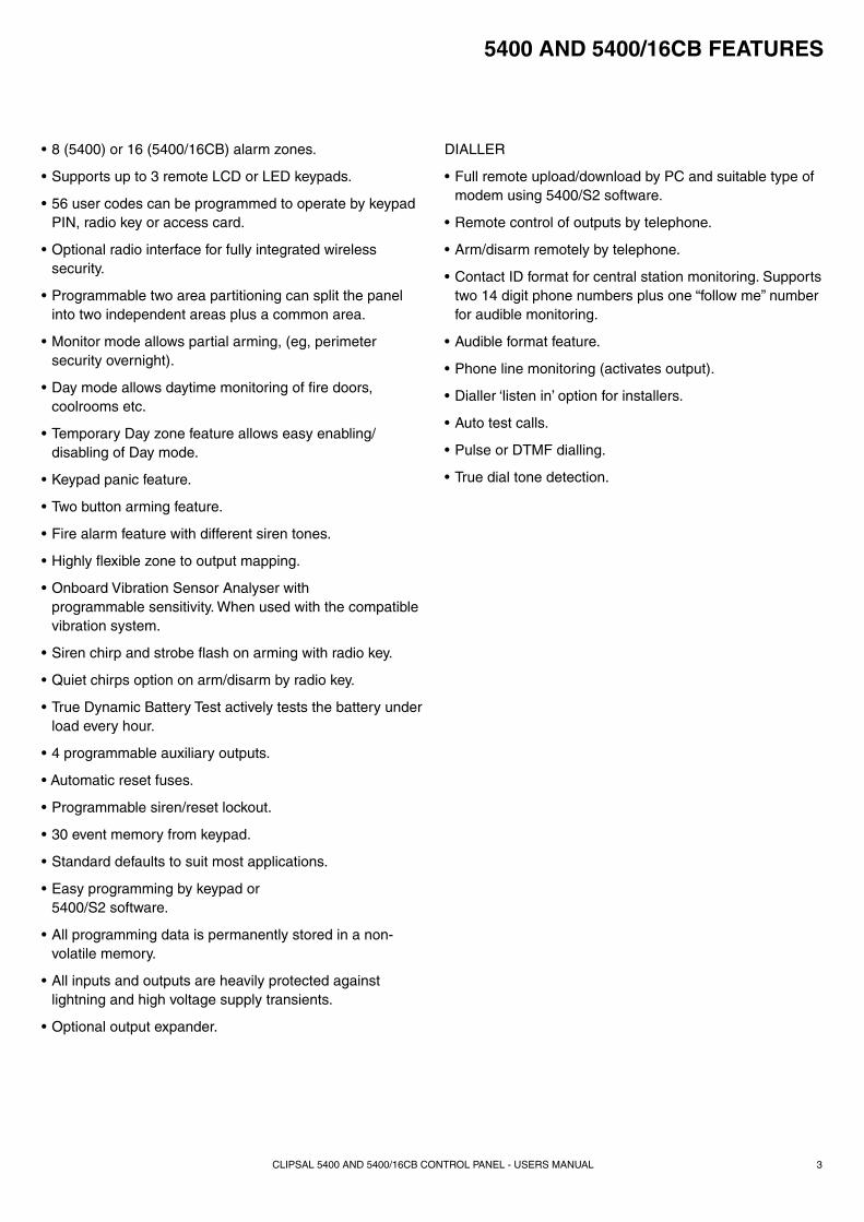
5400 AND 5400/16CB FEATURES
• 8 (5400) or 16 (5400/16CB) alarm zones.
• Supports up to 3 remote LCD or LED keypads.
• 56 user codes can be programmed to operate by keypad PIN, radio key or access card.
• Optional radio interface for fully integrated wireless security.
• Programmable two area partitioning can split the panel into two independent areas plus a common area.
• Monitor mode allows partial arming, (eg, perimeter security overnight).
• Day mode allows daytime monitoring of fi re doors, coolrooms etc.
• Temporary Day zone feature allows easy enabling/disabling of Day mode.
• Keypad panic feature.
• Two button arming feature.
• Fire alarm feature with different siren tones.
• Highly fl exible zone to output mapping.
• Onboard Vibration Sensor Analyser with programmable sensitivity. When used with the compatible vibration system.
• Siren chirp and strobe fl ash on arming with radio key.
• Quiet chirps option on arm/disarm by radio key.
• True Dynamic Battery Test actively tests the battery under load every hour.
• 4 programmable auxiliary outputs.
• Automatic reset fuses.
• Programmable siren/reset lockout.
• 30 event memory from keypad.
• Standard defaults to suit most applications.
• Easy programming by keypad or 5400/S2 software.
• All programming data is permanently stored in a non-volatile memory.
• All inputs and outputs are heavily protected against lightning and high voltage supply transients.
• Optional output expander.
DIALLER
• Full remote upload/download by PC and suitable type of modem using 5400/S2 software.
• Remote control of outputs by telephone.
• Arm/disarm remotely by telephone.
• Contact ID format for central station monitoring. Supports two 14 digit phone numbers plus one “follow me” number for audible monitoring.
• Audible format feature.
• Phone line monitoring (activates output).
• Dialler ‘listen in’ option for installers.
• Auto test calls.
• Pulse or DTMF dialling.
• True dial tone detection.
CLIPSAL 5400 AND 5400/16CB CONTROL PANEL - USERS MANUAL4
INTRODUCTION
The Clipsal 5400 and 5400/16CB microcomputer based 8 or 16 zone control panel is the heart of your security system to which all your detection devices connect.
Each zone of the panel can be connected to one or more detection devices to protect separate rooms of your premises.
Detection devices may be wired to the panel or you can use optional wireless detectors.
Passive Infra-Red motion detectors (PIRs) are used to detect motion of people or animals. Pet Aware motion detectors can ignore pets and still detect people. Reed switches are fi tted to windows and doors to detect opening. Vibration sensors can be used to detect glass breakage or forcing of windows or doors.
Normally a zone is considered sealed. Activation of a detection device will cause the zone to be unsealed and may cause an alarm.
Detectors such as fi re detectors and panic buttons must be able to generate an alarm at all times regardless of the panel setting. A zone with this assignment is called a 24 Hour zone.
Some detection devices may be required to generate an alarm or warning only when the panel is disarmed. A zone with this assignment is called a Day zone.
Before leaving the premises you must "arm" (turn on) the panel. After arming, the panel will ignore detectors during the Exit Delay Time to allow you to exit without triggering an alarm.
The system can be armed and disarmed using the keypad supplied or by optional Radio Keys or Access Cards or Fobs.
When you enter the premises the panel will ignore selected zones for the Entry Delay Time and will not alarm unless you fail to disarm the panel during this allowed time.
When an alarm occurs, it can be reset with a user code1 or by optional Radio Key or Access Card/Fob2, otherwise it will reset at the end of Alarm Reset Time. Resetting an alarm stops the sirens and strobe light. If an alarm is not reset the sirens will stop after the programmed time (default is 5 minutes) and the strobe light will stop after 72 hours.
Monitor mode allows you to arm selected zones while others are ignored. Typically, perimeter zones (doors and windows) can be monitored while you are at home.
If you wish to split your alarm system into two areas with access limited to each area by code numbers then area operation is used. Radio keys can also arm and disarm areas.
The control panel housing and the covers over external sirens are protected by tamper switches to detect someone attempting to disable the security system. Activation of these switches will cause an instant tamper alarm.
If there is a problem with a detector, you can exclude the associated zone so that it is totally ignored and cannot generate an alarm. Including the zone will enable it to generate an alarm again.
The control panel is fi tted with a rechargeable backup battery to ensure your security system continues to operate if the mains power is interrupted. This control panel automatically tests the battery every hour and whenever you arm/disarm the panel. (Dynamic Battery Test).
All alarms are stored in memory and can be viewed at any time in Memory Mode.
1 Keypad codes programmed as ARM ONLY will not reset the panel.
2 Access cards/fobs can reset the panel if the DISARM BY ACCESS CARD option has been enabled by your installer.
CLIPSAL 5400 AND 5400/16CB CONTROL PANEL - USERS MANUAL 5
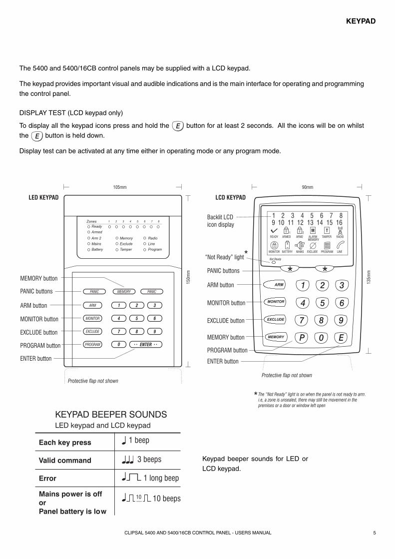
The 5400 and 5400/16CB control panels may be supplied with a LCD keypad.
The keypad provides important visual and audible indications and is the main interface for operating and programming
the control panel.
DISPLAY TEST (LCD keypad only)
To display all the keypad icons press and hold the button for at least 2 seconds. All the icons will be on whilst
the button is held down.
Display test can be activated at any time either in operating mode or any program mode.
2
5
8
0
1
4
7
P
3
6
9
E
ARM
MONITOR
EXCLUDE
MEMORY
Not Ready
Backlit LCDicon display
PANIC buttons
PANIC buttons
“Not Ready” light
The “Not Ready” light is on when the panel is not ready to arm.i.e, a zone is unsealed, there may still be movement in thepremises or a door or window left open
ARM button
ARM button MONITOR button
MONITOR button EXCLUDE button
EXCLUDE button
PROGRAM button
ENTER button
MEMORY button
MEMORY button
LED KEYPAD LCD KEYPAD
PROGRAM button
Protective flap not shownProtective flap not shown
ENTER button
PANIC
ARM 1
4
7
0
2
5
8
ENTER
3
6
9
MONITOR
EXCLUDE
PROGRAM
PANICMEMORY
105mm 90mm15
0mm
135m
m
1 beep
3 beeps
1 long beep
10 beeps
Each key press
Valid command
Error
Mains power is offorPanel battery is low
KEYPAD BEEPER SOUNDSLED keypad and LCD keypad
Keypad beeper sounds for LED or
LCD keypad.
KEYPAD
CLIPSAL 5400 AND 5400/16CB CONTROL PANEL - USERS MANUAL6
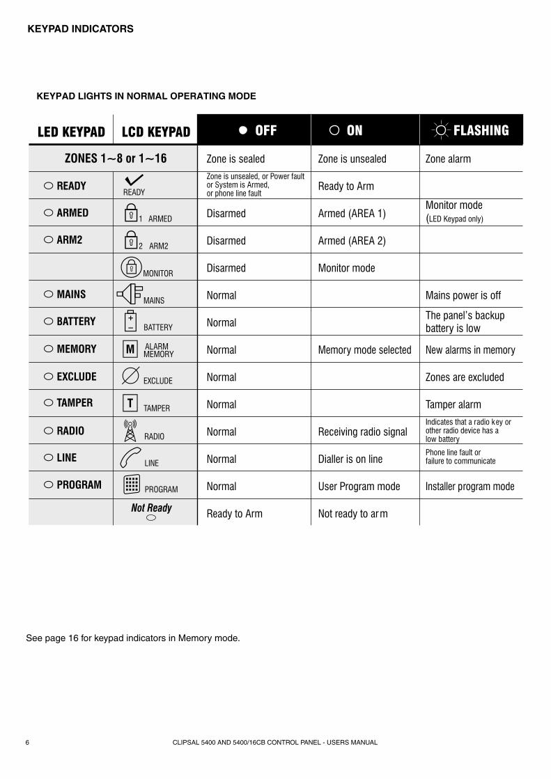
Zone is sealed
Zone is unsealed, or Power faultor System is Armed,or phone line fault
Disarmed
Disarmed
Disarmed
Normal
Normal
Normal
Normal
Normal
Normal
Normal
Normal
Ready to Arm
Zone is unsealed
Ready to Arm
Armed (AREA 1)
Armed (AREA 2)
Monitor mode
Memory mode selected
Receiving radio signal
Dialler is on line
Indicates that a radio key orother radio device has alow battery
Phone line fault orfailure to communicate
User Program mode
Not ready to arm
Zone alarm
Monitor mode(LED Keypad only)
Mains power is off
The panel’s backupbattery is low
New alarms in memory
Zones are excluded
Tamper alarm
Installer program mode
ZONES 1~8 or 1~16
ARMED
ARM2
MAINS
BATTERY
MEMORY
EXCLUDE
TAMPER
PROGRAM
LINE
READY
RADIO
OFF ON FLASHINGLED KEYPAD LCD KEYPAD
See page 16 for keypad indicators in Memory mode.
KEYPAD INDICATORS
CLIPSAL 5400 AND 5400/16CB CONTROL PANEL - USERS MANUAL 7
OPERATION
OPERATING RULES
Generally, the panel will be disarmed. Armed or Monitor modes provide different levels of security for your premises when you are home or away. Three other temporary modes; Program, Memory and Exclude, allow you to perform various operations. The panel will automatically exit from these temporary modes if you do not press any buttons on the keypad in a four minute period.
If you make a mistake while entering any codes, press the Enter or E button and start again.
When you are required to enter your access code, you are given fi ve opportunities to enter it correctly. After the fi fth invalid attempt the alarm is activated (requiring the correct code + E to silence the alarm). This prevents anyone trying to guess your code by entering random numbers.
AREA PARTITIONING
Area partitioning allows the zones to be split into two partitions; Area 1 and Area 2.
The panel then effectively operates as two separate systems sharing only the siren outputs and dialler.
USER CODE ASSIGNMENT
A user code assigned to an area can arm and disarm only that area. User codes assigned to both areas will operate both Areas simultaneously.
COMMON AREA ZONES
Zones assigned to both areas are armed only when Area1 and Area 2 are both armed. This allows the common area zone/s to be shared by both areas.
For example, offi ce A and offi ce B operate as separate areas but the entrance foyer, used by both offi ces, is assigned to both areas meaning it will automatically arm when both areas have armed. The common area then automatically disarms when either Area 1 or Area 2 disarms.
AREA OPERATION
Arming and disarming is carried out as normal from a single keypad or separate keypads installed in both areas or by radio key.
Area operation only applies to zones when they are in the armed state. This means that Day, 24hr and Monitor zones are independent of the area operations.
Note: Area partitioning is in addition to Monitor mode. Any zone may be allocated to any area.
This section describes the operation of a typical control panel installation. Keep in mind that your installation may vary depending on the selected options and equipment. The operating instructions which follow will cover the most common options.
Consult your installation company if you require further information.
All control panel operations are controlled by the keypad except if an optional key switch, radio remote control or access control equipment is installed.
CLIPSAL 5400 AND 5400/16CB CONTROL PANEL - USERS MANUAL8
OPERATION
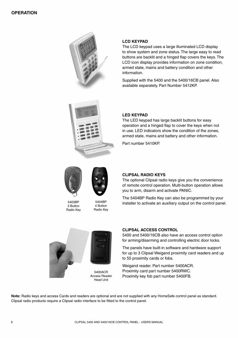
Note: Radio keys and access Cards and readers are optional and are not supplied with any HomeSafe control panel as standard. Clipsal radio products require a Clipsal radio interface to be fi tted to the control panel.
5403BP3 Button
Radio Key
5404BP4 Button
Radio Key
CLIPSAL RADIO KEYSThe optional Clipsal radio keys give you the convenience of remote control operation. Multi-button operation allows you to arm, disarm and activate PANIC.
The 5404BP Radio Key can also be programmed by your installer to activate an auxiliary output on the control panel.
LED KEYPADThe LED keypad has large backlit buttons for easy operation and a hinged fl ap to cover the keys when not in use. LED indicators show the condition of the zones, armed state, mains and battery and other information.
Part number 5410KP.
LCD KEYPADThe LCD keypad uses a large illuminated LCD display to show system and zone status. The large easy to read buttons are backlit and a hinged fl ap covers the keys. The LCD icon display provides information on zone condition, armed state, mains and battery condition and other information.
Supplied with the 5400 and the 5400/16CB panel. Also available separately. Part Number 5412KP.
CLIPSAL ACCESS CONTROL5400 and 5400/16CB also have an access control option for arming/disarming and controlling electric door locks.
The panels have built-in software and hardware support for up to 3 Clipsal Weigand proximity card readers and up to 55 proximity cards or fobs.
Weigand reader. Part number 5400ACR.Proximity card part number 5400RWC.Proximity key fob part number 5400FB.
5400ACRAccess Reader
Head Unit
CLIPSAL 5400 AND 5400/16CB CONTROL PANEL - USERS MANUAL 9
OPERATION
The control panel must be armed in order to detect intruders.
Before arming, all zones should be sealed by making sure there is no movement in rooms protected by motion detectors. Doors or windows protected by reed switches should be closed.
The panel cannot be armed if in Program, Monitor, Memory or Exclude modes or if it is in alarm. (User codes that are programmed to be ARM ONLY codes can arm the panel either the disarmed state or from Monitor mode.
A keypad is supplied with the panel. Operation by radio keys and access cards is optional.
10 10 beeps when you arm means mains power is turned off or the backup battery is low.
One long beep when you arm could mean the panel is already armed or the keypad code is wrong, (if not using shortcut arming).
SIREN WARNING:
At the end of the exit time, all zones should be sealed. If any are unsealed, the siren will sound for 2 seconds to indicate that those zones have been automatically excluded. You should disarm the panel, check the premises and then arm again. Continual warnings could mean there is a problem with a detection device - that zone may have to be manually excluded.
If a zone is unsealed at the end of exit time and the auto-exclude option is disabled, the siren will sound for the duration of siren time, (default is 5 minutes).
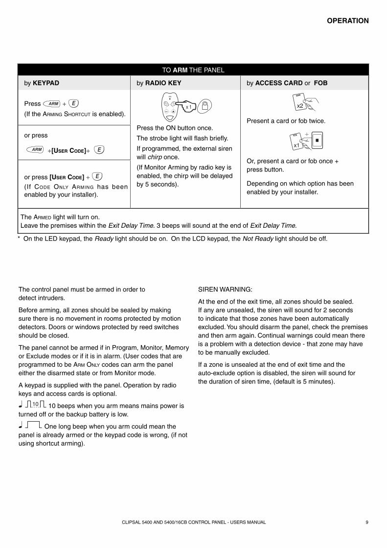
TO ARM THE PANEL
by KEYPAD by RADIO KEY by ACCESS CARD or FOB
Press +
(If the ARMING SHORTCUT is enabled).
Press the ON button once.
The strobe light will fl ash briefl y.
If programmed, the external siren will chirp once.
(If Monitor Arming by radio key is enabled, the chirp will be delayed by 5 seconds).
Present a card or fob twice.
Or, present a card or fob once + press button.
Depending on which option has been enabled by your installer.
or press
+[USER CODE]+
or press [USER CODE] +
(If CODE ONLY ARMING has been enabled by your installer).
The ARMED light will turn on.Leave the premises within the Exit Delay Time. 3 beeps will sound at the end of Exit Delay Time.
* On the LED keypad, the Ready light should be on. On the LCD keypad, the Not Ready light should be off.
CLIPSAL 5400 AND 5400/16CB CONTROL PANEL - USERS MANUAL10
When you enter the protected premises through a delay zone, the keypad responds with regular beeps1 as a reminder to disarm. You then have your programmed entry delay time to disarm the panel.
If the panel is not disarmed by the end of the entry delay time, an alarm will occur.
By using the optional radio keys you may disarm your system from within your premises or from outside your entrance door. There is also the option to ‘chirp’ the outside siren three times and briefl y fl ash the strobe light to indicate that you have disarmed your system.
If you make a mistake when entering your keypad code, then you must press E (or Enter) and start again. Five incorrect entries will cause an alarm.
The panel can be reset and the siren/s silenced by disarming the panel.
If you arrive at your premises and fi nd the strobe light fl ashing2 (if installed), reset the panel as above. To check the cause of the alarm, you can view the alarms in memory by entering Memory mode.
Note: Arm Only codes
User codes can optionally be programmed to be Arm Only codes. An Arm Only code can arm the system but it cannot disarm. However if an Arm Only code is assigned to a radio key, the radio key OFF button will arm and disarm.
1 If entry beeps are enabled.
2 In the event of an alarm, the strobe light will fl ash for 72 hours or until the panel is reset.
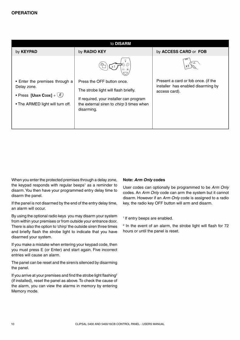
to DISARM
by KEYPAD by RADIO KEY by ACCESS CARD or FOB
• Enter the premises through a Delay zone.
• Press [USER CODE] +
• The ARMED light will turn off.
Press the OFF button once.
The strobe light will fl ash briefl y.
If required, your installer can program the external siren to chirp 3 times when disarming.
Present a card or fob once. (if the installer has enabled disarming by access card).
OPERATION
CLIPSAL 5400 AND 5400/16CB CONTROL PANEL - USERS MANUAL 11
OPERATION
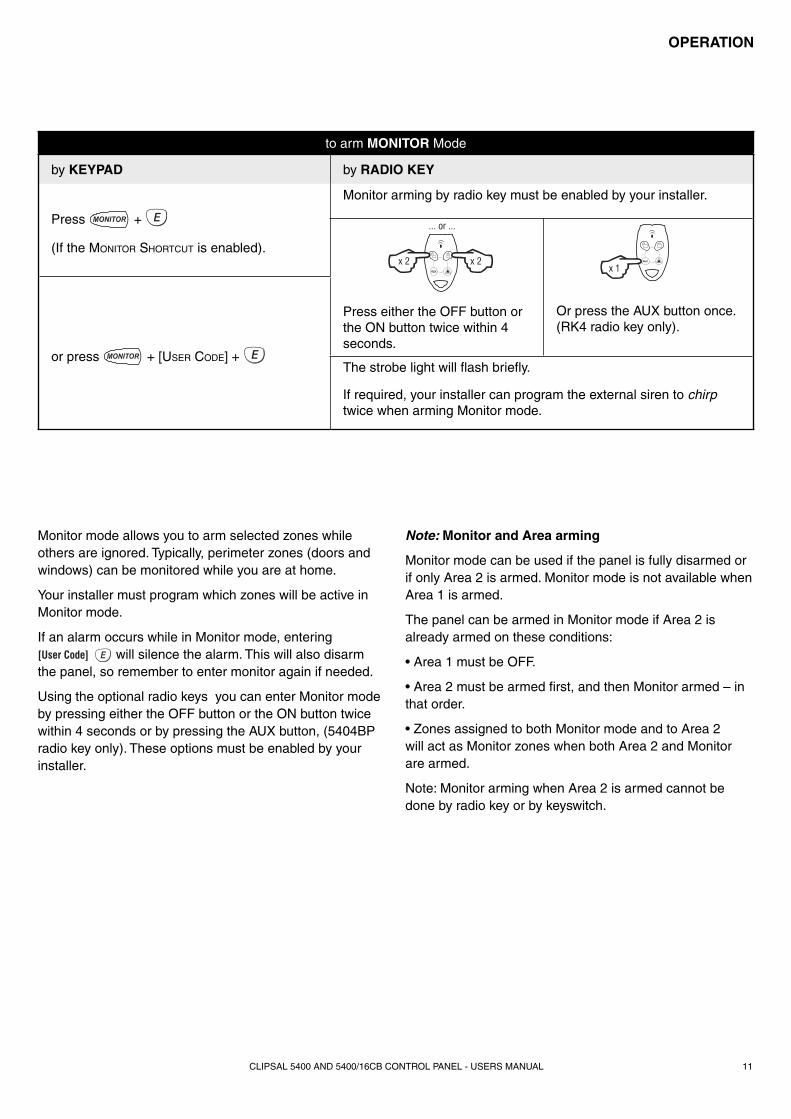
Monitor mode allows you to arm selected zones while others are ignored. Typically, perimeter zones (doors and windows) can be monitored while you are at home.
Your installer must program which zones will be active in Monitor mode.
If an alarm occurs while in Monitor mode, entering [User Code] will silence the alarm. This will also disarm the panel, so remember to enter monitor again if needed.
Using the optional radio keys you can enter Monitor mode by pressing either the OFF button or the ON button twice within 4 seconds or by pressing the AUX button, (5404BP radio key only). These options must be enabled by your installer.
Note: Monitor and Area arming
Monitor mode can be used if the panel is fully disarmed or if only Area 2 is armed. Monitor mode is not available when Area 1 is armed.
The panel can be armed in Monitor mode if Area 2 is already armed on these conditions:
• Area 1 must be OFF.
• Area 2 must be armed fi rst, and then Monitor armed – in that order.
• Zones assigned to both Monitor mode and to Area 2 will act as Monitor zones when both Area 2 and Monitor are armed.
Note: Monitor arming when Area 2 is armed cannot be done by radio key or by keyswitch.
to arm MONITOR Mode
by KEYPAD by RADIO KEY
Press +
(If the MONITOR SHORTCUT is enabled).
Monitor arming by radio key must be enabled by your installer.
Press either the OFF button or the ON button twice within 4 seconds.
Or press the AUX button once. (RK4 radio key only).
or press + [USER CODE] + The strobe light will fl ash briefl y.
If required, your installer can program the external siren to chirp twice when arming Monitor mode.
CLIPSAL 5400 AND 5400/16CB CONTROL PANEL - USERS MANUAL12
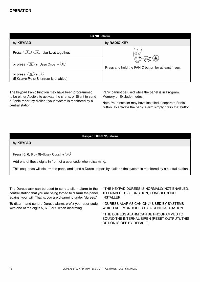
The keypad Panic function may have been programmed to be either Audible to activate the sirens, or Silent to send a Panic report by dialler if your system is monitored by a central station.
Panic cannot be used while the panel is in Program, Memory or Exclude modes.
Note: Your installer may have installed a separate Panic button. To activate the panic alarm simply press that button.
The Duress arm can be used to send a silent alarm to the central station that you are being forced to disarm the panel against your will. That is; you are disarming under “duress.”
To disarm and send a Duress alarm, prefi x your user code with one of the digits 5, 6, 8 or 9 when disarming.
* THE KEYPAD DURESS IS NORMALLY NOT ENABLED. TO ENABLE THIS FUNCTION, CONSULT YOUR INSTALLER.
* DURESS ALARMS CAN ONLY USED BY SYSTEMS WHICH ARE MONITORED BY A CENTRAL STATION.
* THE DURESS ALARM CAN BE PROGRAMMED TO SOUND THE INTERNAL SIREN (RESET OUTPUT). THIS OPTION IS OFF BY DEFAULT.
PANIC alarm
by KEYPAD by RADIO KEY
Press star keys together.
Press and hold the PANIC button for at least 4 sec.or press + [USER CODE] +
or press + (If KEYPAD PANIC SHORTCUT is enabled).
Keypad DURESS alarm
by KEYPAD
Press [5, 6, 8 OR 9]+[USER CODE] +
Add one of these digits in front of a user code when disarming.
This sequence will disarm the panel and send a Duress report by dialler if the system is monitored by a central station.
OPERATION
CLIPSAL 5400 AND 5400/16CB CONTROL PANEL - USERS MANUAL 13
OPERATION
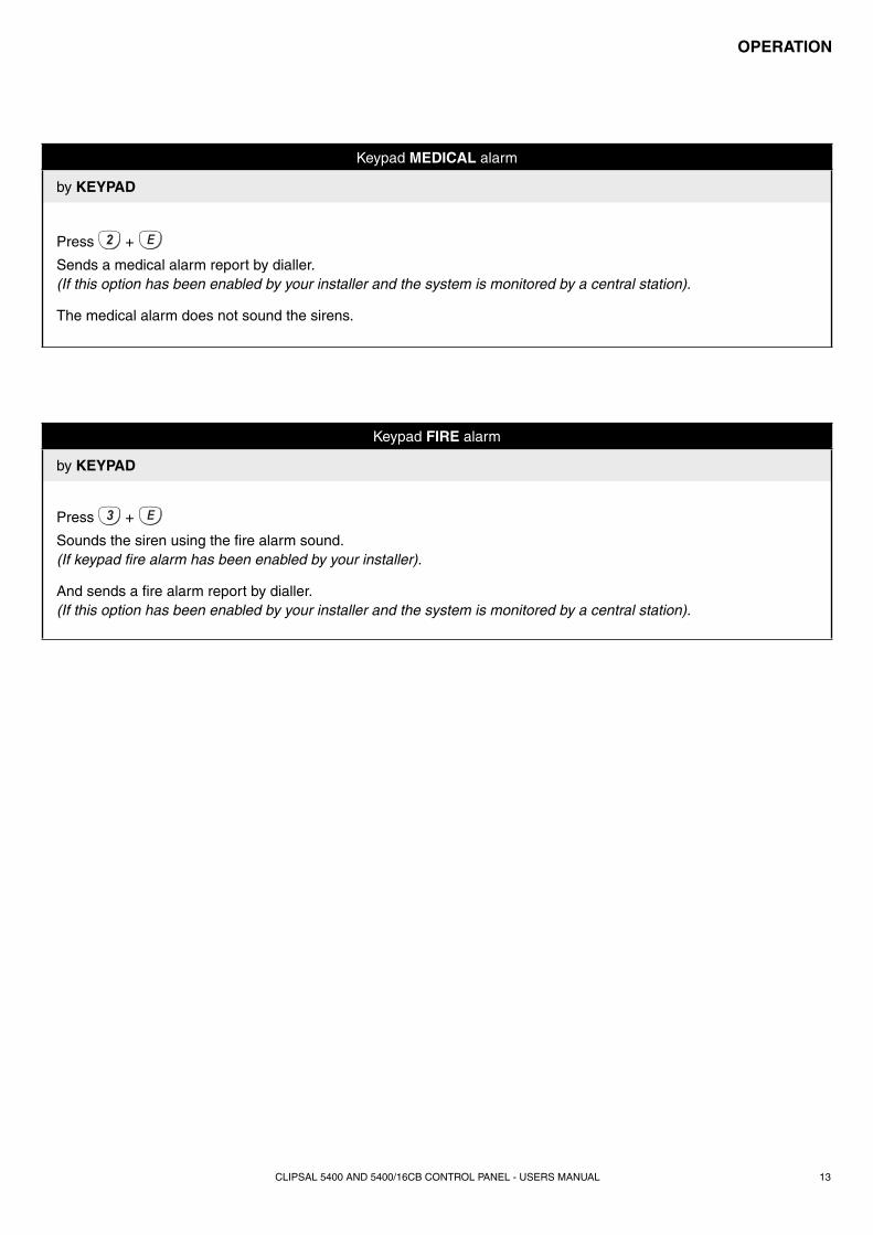
Keypad FIRE alarm
by KEYPAD
Press +
Sounds the siren using the fi re alarm sound.(If keypad fi re alarm has been enabled by your installer).
And sends a fi re alarm report by dialler.(If this option has been enabled by your installer and the system is monitored by a central station).
Keypad MEDICAL alarm
by KEYPAD
Press +
Sends a medical alarm report by dialler.(If this option has been enabled by your installer and the system is monitored by a central station).
The medical alarm does not sound the sirens.
CLIPSAL 5400 AND 5400/16CB CONTROL PANEL - USERS MANUAL14
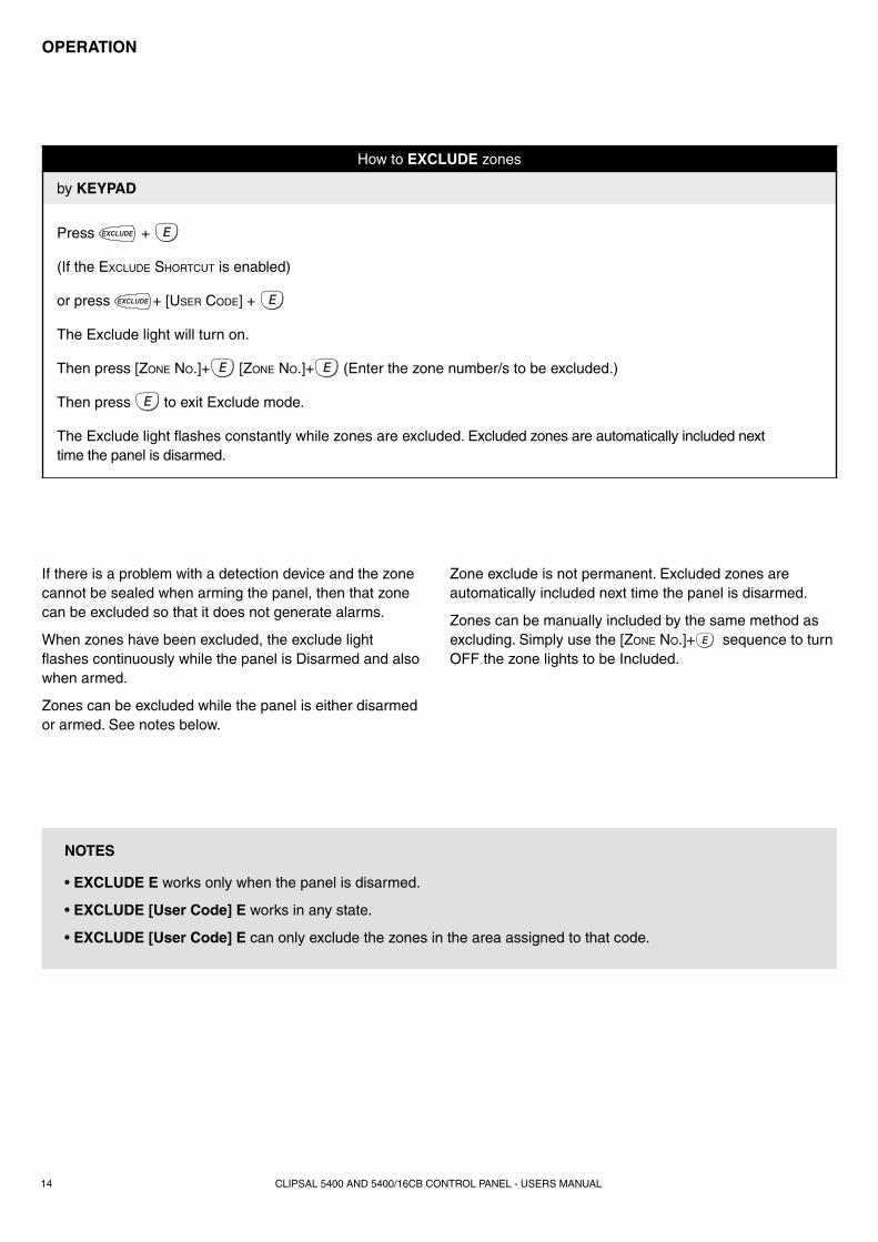
If there is a problem with a detection device and the zone cannot be sealed when arming the panel, then that zone can be excluded so that it does not generate alarms.
When zones have been excluded, the exclude light fl ashes continuously while the panel is Disarmed and also when armed.
Zones can be excluded while the panel is either disarmed or armed. See notes below.
Zone exclude is not permanent. Excluded zones are automatically included next time the panel is disarmed.
Zones can be manually included by the same method as excluding. Simply use the [ZONE NO.]+ sequence to turn OFF the zone lights to be Included.
NOTES
• EXCLUDE E works only when the panel is disarmed.
• EXCLUDE [User Code] E works in any state.
• EXCLUDE [User Code] E can only exclude the zones in the area assigned to that code.
How to EXCLUDE zones
by KEYPAD
Press +
(If the EXCLUDE SHORTCUT is enabled)
or press + [USER CODE] +
The Exclude light will turn on.
Then press [ZONE NO.]+ [ZONE NO.]+ (Enter the zone number/s to be excluded.)
Then press to exit Exclude mode.
The Exclude light fl ashes constantly while zones are excluded. Excluded zones are automatically included next time the panel is disarmed.
OPERATION
CLIPSAL 5400 AND 5400/16CB CONTROL PANEL - USERS MANUAL 15
OPERATION
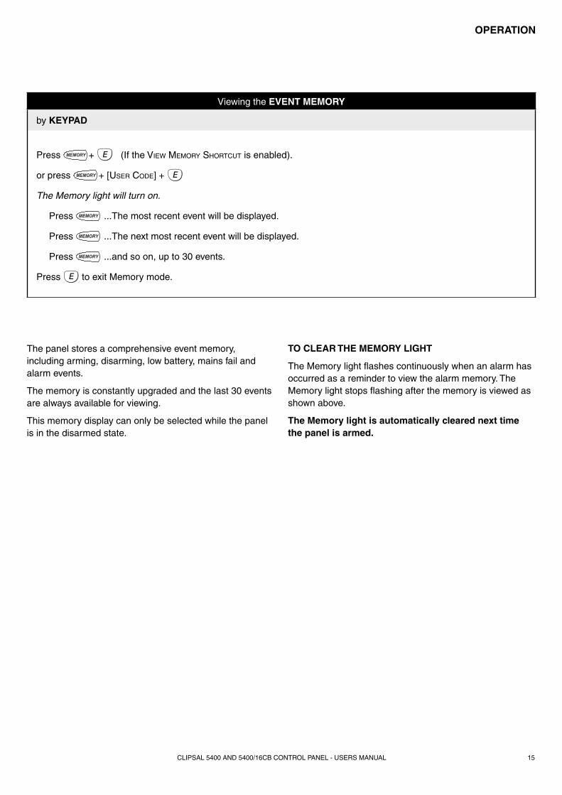
The panel stores a comprehensive event memory, including arming, disarming, low battery, mains fail and alarm events.
The memory is constantly upgraded and the last 30 events are always available for viewing.
This memory display can only be selected while the panel is in the disarmed state.
TO CLEAR THE MEMORY LIGHT
The Memory light fl ashes continuously when an alarm has occurred as a reminder to view the alarm memory. The Memory light stops fl ashing after the memory is viewed as shown above.
The Memory light is automatically cleared next time the panel is armed.
Viewing the EVENT MEMORY
by KEYPAD
Press + (If the VIEW MEMORY SHORTCUT is enabled).
or press + [USER CODE] +
The Memory light will turn on.
Press ...The most recent event will be displayed.
Press ...The next most recent event will be displayed.
Press ...and so on, up to 30 events.
Press to exit Memory mode.
CLIPSAL 5400 AND 5400/16CB CONTROL PANEL - USERS MANUAL16
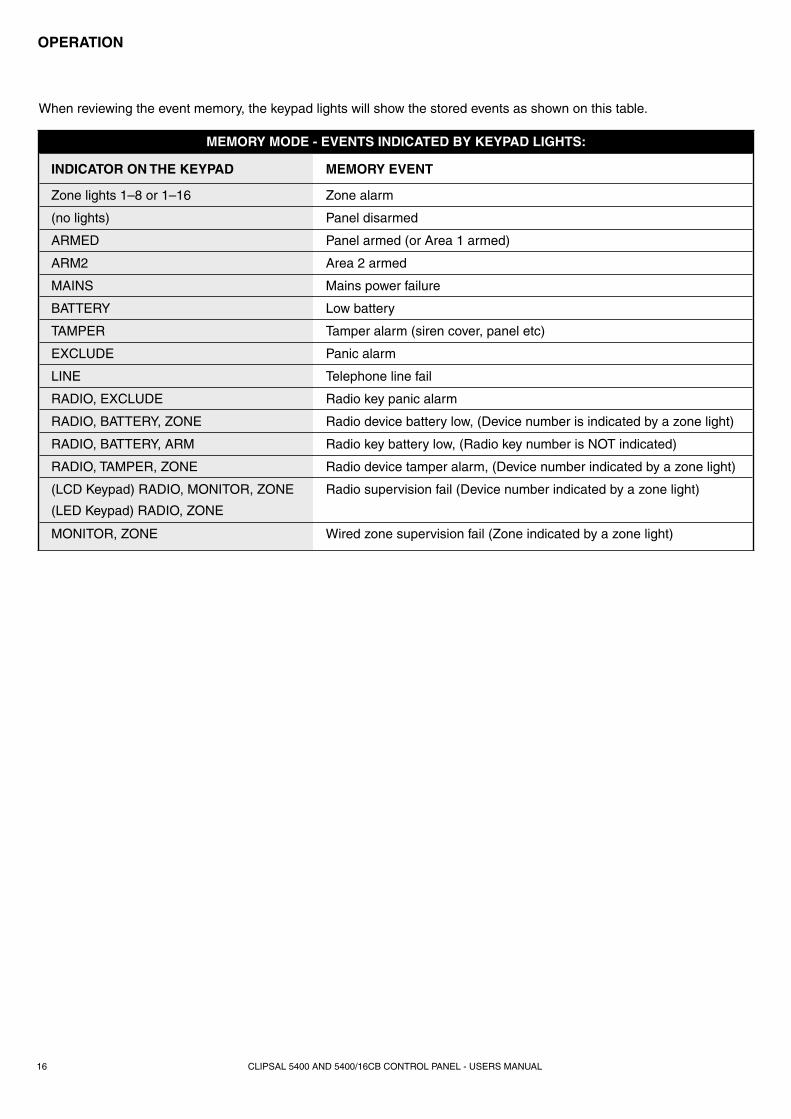
MEMORY MODE - EVENTS INDICATED BY KEYPAD LIGHTS:
INDICATOR ON THE KEYPAD MEMORY EVENT
Zone lights 1–8 or 1–16 Zone alarm
(no lights) Panel disarmed
ARMED Panel armed (or Area 1 armed)
ARM2 Area 2 armed
MAINS Mains power failure
BATTERY Low battery
TAMPER Tamper alarm (siren cover, panel etc)
EXCLUDE Panic alarm
LINE Telephone line fail
RADIO, EXCLUDE Radio key panic alarm
RADIO, BATTERY, ZONE Radio device battery low, (Device number is indicated by a zone light)
RADIO, BATTERY, ARM Radio key battery low, (Radio key number is NOT indicated)
RADIO, TAMPER, ZONE Radio device tamper alarm, (Device number indicated by a zone light)
(LCD Keypad) RADIO, MONITOR, ZONE
(LED Keypad) RADIO, ZONE
Radio supervision fail (Device number indicated by a zone light)
MONITOR, ZONE Wired zone supervision fail (Zone indicated by a zone light)
OPERATION
When reviewing the event memory, the keypad lights will show the stored events as shown on this table.
CLIPSAL 5400 AND 5400/16CB CONTROL PANEL - USERS MANUAL 17
The Clipsal 5400 and 5400/16CB have a Temporary Day zone feature which allows easy and fl exible Day Zone selection and operation.
Temporary Day zones operate in addition to Permanent Day zones which are usually setup by the installer.
While remaining in normal operating mode, the user can add and remove ‘Temporary Day’ zones.
As an extra feature, the user can easily enable or disable Day mode, (which includes both Temporary and Permanent Day zones).
Day zones can be programmed by your installer to beep the keypad, or briefl y sound the siren/s or fl ash the strobe light, or to sound an optional buzzer. (Although the keypad beeper provides suffi cient warning in most situations).
TYPICAL APPLICATIONSDay zones are useful for a variety of applications such as a shop door beeper, triggered by a reed switch on the door.
For example, in a shop you could enable Day mode to alert you when a customer enters the front door.
You can also enable additional Temporary Day zones to monitor switches on, for example, the rear door or the fridge doors.
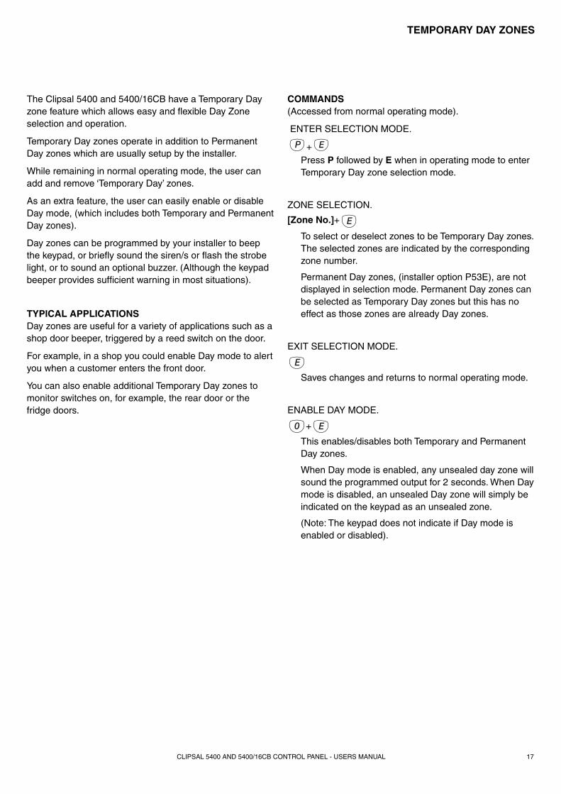
COMMANDS(Accessed from normal operating mode).
ENTER SELECTION MODE.
+
Press P followed by E when in operating mode to enter Temporary Day zone selection mode.
ZONE SELECTION.
[Zone No.]+
To select or deselect zones to be Temporary Day zones. The selected zones are indicated by the corresponding zone number.
Permanent Day zones, (installer option P53E), are not displayed in selection mode. Permanent Day zones can be selected as Temporary Day zones but this has no effect as those zones are already Day zones.
EXIT SELECTION MODE.
Saves changes and returns to normal operating mode.
ENABLE DAY MODE.
+ This enables/disables both Temporary and Permanent Day zones.
When Day mode is enabled, any unsealed day zone will sound the programmed output for 2 seconds. When Day mode is disabled, an unsealed Day zone will simply be indicated on the keypad as an unsealed zone.
(Note: The keypad does not indicate if Day mode is enabled or disabled).
TEMPORARY DAY ZONES

CLIPSAL 5400 AND 5400/16CB CONTROL PANEL - USERS MANUAL18
EXAMPLEAn example of how to select zones 1, 2 & 3 as Temporary Day zones.
Note that Permanent Day zones which have been programmed by the installer cannot be deselected by this method. However, the user can disable Day mode using the 0+E command.
TEMPORARY DAY ZONES
CLIPSAL 5400 AND 5400/16CB CONTROL PANEL - USERS MANUAL 19
PROGRAMMING
[Master code]
[Master code]
ENTER
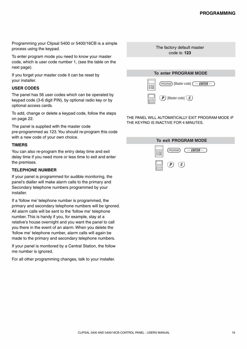
To enter PROGRAM MODE
ENTER
To exit PROGRAM MODE
Programming your Clipsal 5400 or 5400/16CB is a simple process using the keypad.
To enter program mode you need to know your master code, which is user code number 1, (see the table on the next page).
If you forget your master code it can be reset by your installer.
USER CODES
The panel has 56 user codes which can be operated by keypad code (3-6 digit PIN), by optional radio key or by optional access cards.
To add, change or delete a keypad code, follow the steps on page 22.
The panel is supplied with the master code pre-programmed as 123. You should re-program this code with a new code of your own choice.
TIMERS
You can also re-program the entry delay time and exit delay time if you need more or less time to exit and enter the premises.
TELEPHONE NUMBER
If your panel is programmed for audible monitoring, the panel's dialler will make alarm calls to the primary and Secondary telephone numbers programmed by your installer.
If a ‘follow me’ telephone number is programmed, the primary and secondary telephone numbers will be ignored. All alarm calls will be sent to the 'follow me' telephone number. This is handy if you, for example, stay at a relative's house overnight and you want the panel to call you there in the event of an alarm. When you delete the 'follow me' telephone number, alarm calls will again be made to the primary and secondary telephone numbers.
If your panel is monitored by a Central Station, the follow me number is ignored.
For all other programming changes, talk to your installer.
The factory default master code is: 123
THE PANEL WILL AUTOMATICALLY EXIT PROGRAM MODE IF THE KEYPAD IS INACTIVE FOR 4 MINUTES.
CLIPSAL 5400 AND 5400/16CB CONTROL PANEL - USERS MANUAL20
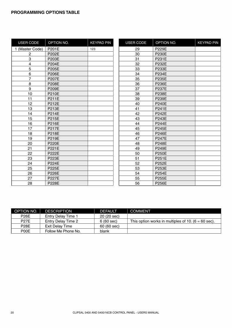
PROGRAMMING OPTIONS TABLE
USER CODE OPTION NO. KEYPAD PIN
1 (Master Code) P201E 123
2 P202E 3 P203E 4 P204E 5 P205E 6 P206E 7 P207E 8 P208E 9 P209E 10 P210E 11 P211E 12 P212E 13 P213E 14 P214E 15 P215E 16 P216E 17 P217E 18 P218E 19 P219E 20 P220E 21 P221E 22 P222E 23 P223E 24 P224E 25 P225E 26 P226E 27 P227E 28 P228E
USER CODE OPTION NO. KEYPAD PIN
29 P229E 30 P230E 31 P231E 32 P232E 33 P233E 34 P234E 35 P235E 36 P236E 37 P237E 38 P238E 39 P239E 40 P240E 41 P241E 42 P242E 43 P243E 44 P244E 45 P245E 46 P246E 47 P247E 48 P248E 49 P249E 50 P250E 51 P251E 52 P252E 53 P253E 54 P254E 55 P255E 56 P256E
OPTION NO. DESCRIPTION DEFAULT COMMENTP26E Entry Delay Time 1 20 (20 sec)P27E Entry Delay Time 2 6 (60 sec) This option works in multiples of 10. (6 = 60 sec).P28E Exit Delay Time 60 (60 sec)P00E Follow Me Phone No. blank

CLIPSAL 5400 AND 5400/16CB CONTROL PANEL - USERS MANUAL 21
PROGRAMMING
EXAMPLES
The panel must be in program mode.
• To program user code 1 to be 1234: Press P201E 1234 E 1234 E
• To delete user code 2 without programming a new code: P202E MEMORY E
USER CODE PROGRAMMING RULES:
• Up to 56 keypad codes can be used at up to three wired keypads for controlling all panel functions including arming/disarming, monitor mode, panic, memory recall and much more.
• Keypad codes can be 3 to 6 digits in length and can be individually programmed and deleted.
• User code 1 is also the master code which is used to enter client program mode.
• All 56 user codes are keypad codes by default. User codes can be programmed to be radio codes or access cards as required.
Programming USER CODES
STEP KEYSTROKES DESCRIPTION COMMENT
1 +[MASTER CODE]+ Enters user program mode. The program light will turn on.
2 +[OPTION NO.]+ Enter the 3 digit option number for the user code being programmed.
The existing user code, if any, will be displayed by the keypad one digit at a time.
3 [NEW CODE]+ [NEW CODE]+
Enter the new user code twice for verifi cation. Keypad codes can be 3-6 digits long.
The new user code will be displayed by the keypad one digit at a time.
4 + To exit user program mode. The program light will turn off.
A keypad code can be deleted by pressing + at STEP 3 above.
A keypad code only needs to be deleted if you're not replacing it with a new code.
NOTES
1. Keypad codes beginning with 0 (zero) can be programmed but they will not operate the panel. This is an alternative method for disabling user codes.
2. All codes must be unique to each other. Codes are rejected if already used. Some codes that are similar to existing codes may also be rejected.
3. When re-programming a keypad code, the old code does not need to be deleted fi rst. The new code will overwrite the old code.
CLIPSAL 5400 AND 5400/16CB CONTROL PANEL - USERS MANUAL22
PROGRAMMING
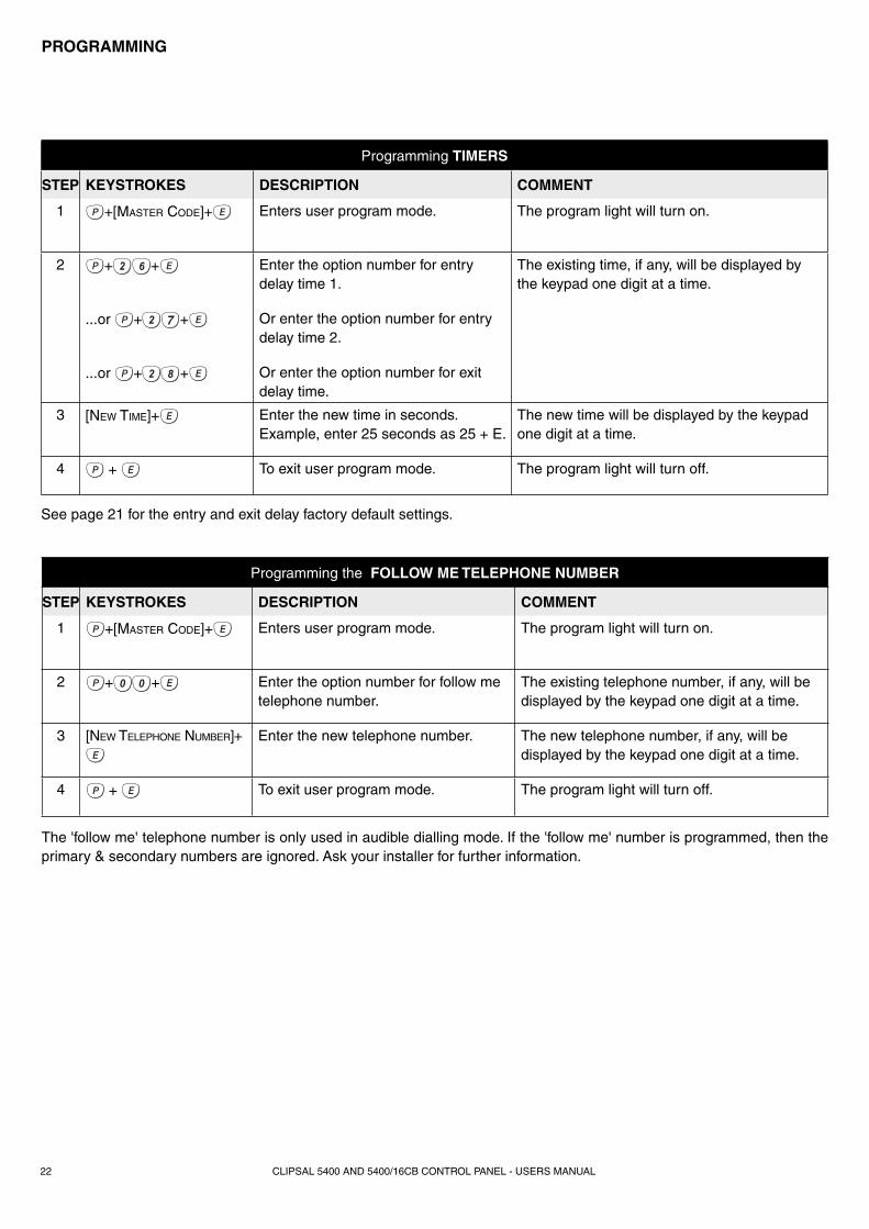
Programming TIMERS
STEP KEYSTROKES DESCRIPTION COMMENT
1 +[MASTER CODE]+ Enters user program mode. The program light will turn on.
2 + + Enter the option number for entry delay time 1.
The existing time, if any, will be displayed by the keypad one digit at a time.
...or + + Or enter the option number for entry delay time 2.
...or + + Or enter the option number for exit delay time.
3 [NEW TIME]+ Enter the new time in seconds. Example, enter 25 seconds as 25 + E.
The new time will be displayed by the keypad one digit at a time.
4 + To exit user program mode. The program light will turn off.
See page 21 for the entry and exit delay factory default settings.
Programming the FOLLOW ME TELEPHONE NUMBER
STEP KEYSTROKES DESCRIPTION COMMENT
1 +[MASTER CODE]+ Enters user program mode. The program light will turn on.
2 + + Enter the option number for follow me telephone number.
The existing telephone number, if any, will be displayed by the keypad one digit at a time.
3 [NEW TELEPHONE NUMBER]+ Enter the new telephone number. The new telephone number, if any, will be displayed by the keypad one digit at a time.
4 + To exit user program mode. The program light will turn off.
The 'follow me' telephone number is only used in audible dialling mode. If the 'follow me' number is programmed, then the primary & secondary numbers are ignored. Ask your installer for further information.
CLIPSAL 5400 AND 5400/16CB CONTROL PANEL - USERS MANUAL 23
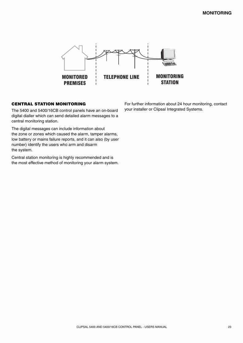
CENTRAL STATION MONITORING
The 5400 and 5400/16CB control panels have an on-board digital dialler which can send detailed alarm messages to a central monitoring station.
The digital messages can include information about the zone or zones which caused the alarm, tamper alarms, low battery or mains failure reports, and it can also (by user number) identify the users who arm and disarm the system.
Central station monitoring is highly recommended and is the most effective method of monitoring your alarm system.
MONITORING
MONITOREDPREMISES
TELEPHONE LINE MONITORINGSTATION
For further information about 24 hour monitoring, contact your installer or Clipsal Integrated Systems.
CLIPSAL 5400 AND 5400/16CB CONTROL PANEL - USERS MANUAL24
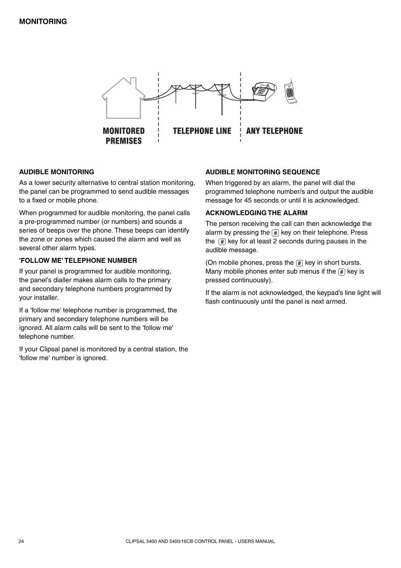
MONITOREDPREMISES
TELEPHONE LINE ANY TELEPHONE
AUDIBLE MONITORING
As a lower security alternative to central station monitoring, the panel can be programmed to send audible messages to a fi xed or mobile phone.
When programmed for audible monitoring, the panel calls a pre-programmed number (or numbers) and sounds a series of beeps over the phone. These beeps can identify the zone or zones which caused the alarm and well as several other alarm types.
'FOLLOW ME' TELEPHONE NUMBER
If your panel is programmed for audible monitoring, the panel's dialler makes alarm calls to the primary and secondary telephone numbers programmed by your installer.
If a 'follow me' telephone number is programmed, the primary and secondary telephone numbers will be ignored. All alarm calls will be sent to the 'follow me' telephone number.
If your Clipsal panel is monitored by a central station, the 'follow me' number is ignored.
AUDIBLE MONITORING SEQUENCE
When triggered by an alarm, the panel will dial the programmed telephone number/s and output the audible message for 45 seconds or until it is acknowledged.
ACKNOWLEDGING THE ALARM
The person receiving the call can then acknowledge the alarm by pressing the key on their telephone. Press the key for at least 2 seconds during pauses in the audible message.
(On mobile phones, press the key in short bursts. Many mobile phones enter sub menus if the key is pressed continuously).
If the alarm is not acknowledged, the keypad’s line light will fl ash continuously until the panel is next armed.
MONITORING
CLIPSAL 5400 AND 5400/16CB CONTROL PANEL - USERS MANUAL 25
REMOTE OPERATION
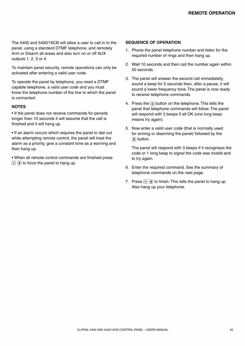
The 5400 and 5400/16CB will allow a user to call in to the panel, using a standard DTMF telephone, and remotely Arm or Disarm all areas and also turn on or off AUX outputs 1, 2, 3 or 4.
To maintain panel security, remote operations can only be activated after entering a valid user code.
To operate the panel by telephone, you need a DTMF capable telephone, a valid user code and you must know the telephone number of the line to which the panel is connected.
NOTES
• If the panel does not receive commands for periods longer than 10 seconds it will assume that the call is fi nished and it will hang up.
• If an alarm occurs which requires the panel to dial out while attempting remote control, the panel will treat the alarm as a priority, give a constant tone as a warning and then hang up.
• When all remote control commands are fi nished press to force the panel to hang up.
SEQUENCE OF OPERATION
1. Phone the panel telephone number and listen for the required number of rings and then hang up.
2. Wait 10 seconds and then call the number again within 50 seconds.
3. The panel will answer the second call immediately, sound a beep for 2 seconds then, after a pause, it will sound a lower frequency tone. The panel is now ready to receive telephone commands.
4. Press the button on the telephone. This tells the panel that telephone commands will follow. The panel will respond with 3 beeps if all OK (one long beep means try again).
5. Now enter a valid user code (that is normally used for arming or disarming the panel) followed by the
button.
The panel will respond with 3 beeps if it recognises the code or 1 long beep to signal the code was invalid and to try again.
6. Enter the required command. See the summary of telephone commands on the next page.
7. Press to fi nish. This tells the panel to hang up. Also hang up your telephone.
CLIPSAL 5400 AND 5400/16CB CONTROL PANEL - USERS MANUAL26
REMOTE OPERATION
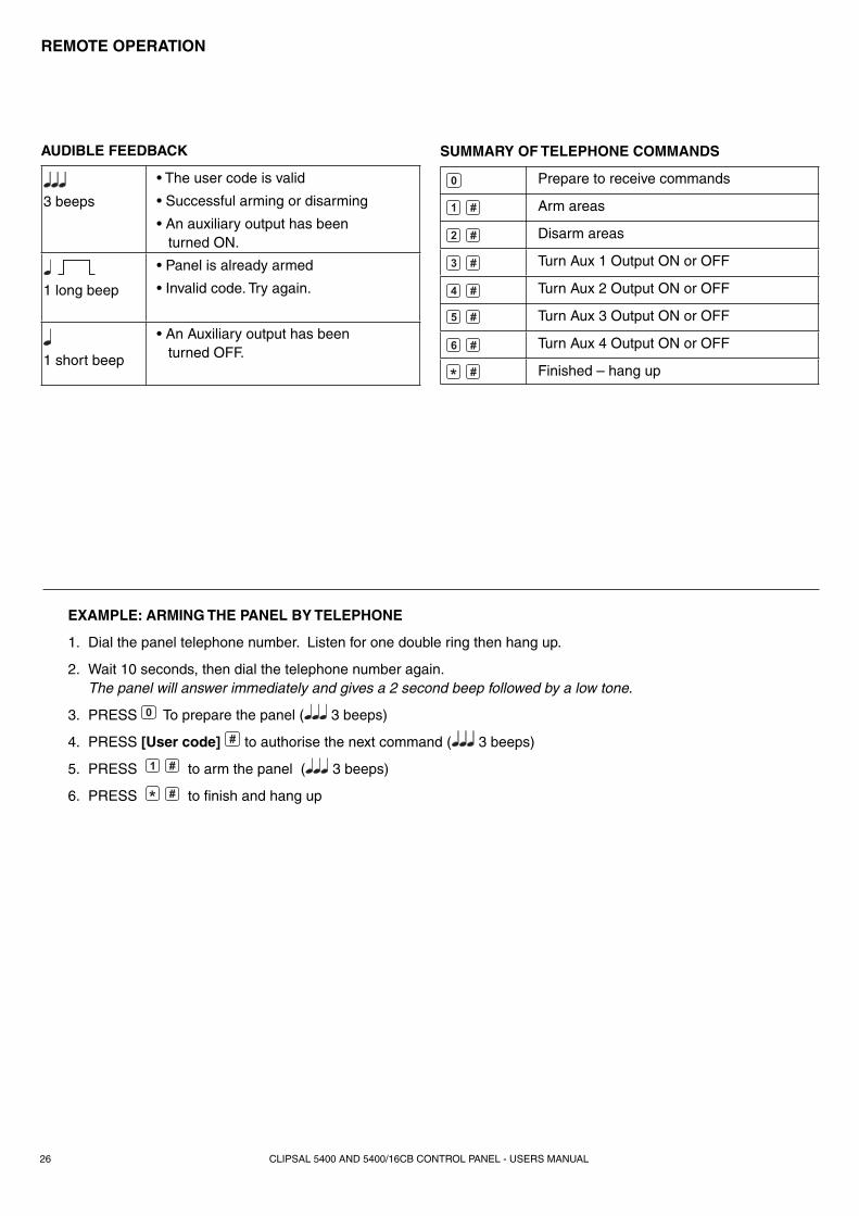
EXAMPLE: ARMING THE PANEL BY TELEPHONE
1. Dial the panel telephone number. Listen for one double ring then hang up.
2. Wait 10 seconds, then dial the telephone number again. The panel will answer immediately and gives a 2 second beep followed by a low tone.
3. PRESS To prepare the panel ( 3 beeps)
4. PRESS [User code] to authorise the next command ( 3 beeps)
5. PRESS to arm the panel ( 3 beeps)
6. PRESS to fi nish and hang up
SUMMARY OF TELEPHONE COMMANDS
Prepare to receive commands
Arm areas
Disarm areas
Turn Aux 1 Output ON or OFF
Turn Aux 2 Output ON or OFF
Turn Aux 3 Output ON or OFF
Turn Aux 4 Output ON or OFF
Finished – hang up
AUDIBLE FEEDBACK
3 beeps
• The user code is valid
• Successful arming or disarming
• An auxiliary output has been turned ON.
1 long beep
• Panel is already armed
• Invalid code. Try again.
1 short beep
• An Auxiliary output has been turned OFF.
27
TROUBLESHOOTING
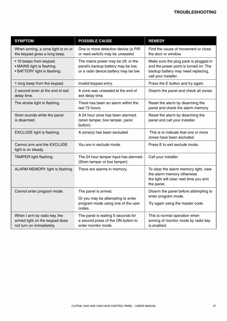
SYMPTOM POSSIBLE CAUSE REMEDY
When arming, a zone light is on or the keypad gives a long beep.
One or more detection device (a PIR or reed switch) may be unsealed.
Find the cause of movement or close the door or window.
• 10 beeps from keypad. • MAINS light is fl ashing.• BATTERY light is fl ashing.
The mains power may be off, or the panel’s backup battery may be low,or a radio device battery may be low.
Make sure the plug pack is plugged in and the power point is turned on. The backup battery may need replacing, call your installer.
1 long beep from the keypad. Invalid keypad entry. Press the E button and try again.
2 second siren at the end of exit delay time.
A zone was unsealed at the end of exit delay time.
Disarm the panel and check all zones.
The strobe light is fl ashing. There has been an alarm within the last 72 hours.
Reset the alarm by disarming the panel and check the alarm memory
Siren sounds while the panel is disarmed.
A 24 hour zone has been alarmed. (siren tamper, box tamper, panic button).
Reset the alarm by disarming the panel and call your installer.
EXCLUDE light is fl ashing. A zone(s) has been excluded. This is to indicate that one or more zones have been excluded.
Cannot arm and the EXCLUDE light is on steady.
You are in exclude mode. Press E to exit exclude mode.
TAMPER light fl ashing. The 24 hour tamper input has alarmed. (Siren tamper or box tamper).
Call your installer.
ALARM MEMORY light is fl ashing. There are alarms in memory. To clear the alarm memory light, view the alarm memory otherwise the light will clear next time you arm the panel.
Cannot enter program mode. The panel is armed.
Or you may be attempting to enter program mode using one of the user codes.
Disarm the panel before attempting to enter program mode.
Try again using the master code.
When I arm by radio key, the armed light on the keypad does not turn on immediately.
The panel is waiting 5 seconds for a second press of the ON button to enter monitor mode.
This is normal operation when arming of monitor mode by radio key is enabled.
CLIPSAL 5400 AND 5400/16CB CONTROL PANEL - USERS MANUAL
CLIPSAL 5400 AND 5400/16CB CONTROL PANEL - USERS MANUAL
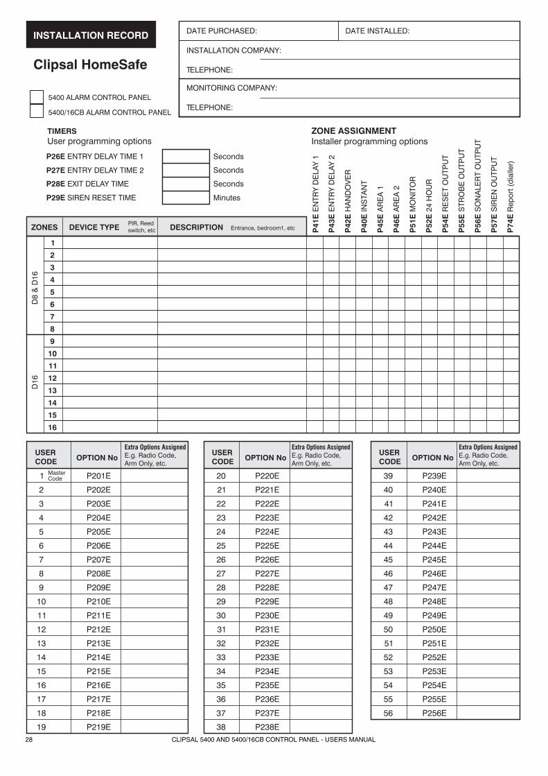
DATE PURCHASED: DATE INSTALLED:
INSTALLATION COMPANY:
TELEPHONE:
ZONES
D8
& D
16D
16
DEVICE TYPEPIR, Reedswitch, etc Entrance, bedroom1, etcDESCRIPTION P
41E
EN
TRY
DE
LAY
1
ZONE ASSIGNMENTInstaller programming options
TIMERSUser programming options
P43
EE
NTR
Y D
ELA
Y 2
P42
EH
AN
DO
VE
R
P40
EIN
STA
NT
P45
EA
RE
A 1
P46
EA
RE
A 2
P51
EM
ON
ITO
R
P52
E2 4
HO
UR
P54
ER
ES
ET
OU
TPU
T
P55
ES
TRO
BE
OU
TPU
T
P56
ES
ON
ALE
RT
OU
TPU
T
P57
ES
IRE
N O
UTP
UT
P74
ER
epor
t (di
alle
r)
1
2
3
4
5
6
7
8
9
10
11
12
13
14
15
16
P26E ENTRY DELAY TIME 1 Seconds
Seconds
Seconds
Minutes
P27E ENTRY DELAY TIME 2
P28E EXIT DELAY TIME
P29E SIREN RESET TIME
MONITORING COMPANY:
TELEPHONE:
USERCODE
USERCODE
USERCODEOPTION No OPTION No OPTION No
Extra Options AssignedE.g. Radio Code,Arm Only, etc.
Extra Options AssignedE.g. Radio Code,Arm Only, etc.
Extra Options AssignedE.g. Radio Code,Arm Only, etc.
1 20 39P201E P220E P239EMasterCode
2 21 40P202E P221E P240E
3 22 41P203E P222E P241E
4 23 42P204E P223E P242E
5 24 43P205E P224E P243E
6 25 44P206E P225E P244E
7 26 45P207E P226E P245E
8 27 46P208E P227E P246E
9 28 47P209E P228E P247E
10 29 48P210E P229E P248E
11 30 49P211E P230E P249E
12 31 50P212E P231E P250E
13 32 51P213E P232E P251E
14 33 52P214E P233E P252E
15 34 53
16 35 54
17 36 55
18 37 56
19 38
P215E P234E P253E
P216E P235E P254E
P217E P236E P255E
P218E P237E P256E
P219E P238E
5400 ALARM CONTROL PANEL
INSTALLATION RECORD
Clipsal HomeSafe
5400/16CB ALARM CONTROL PANEL
28
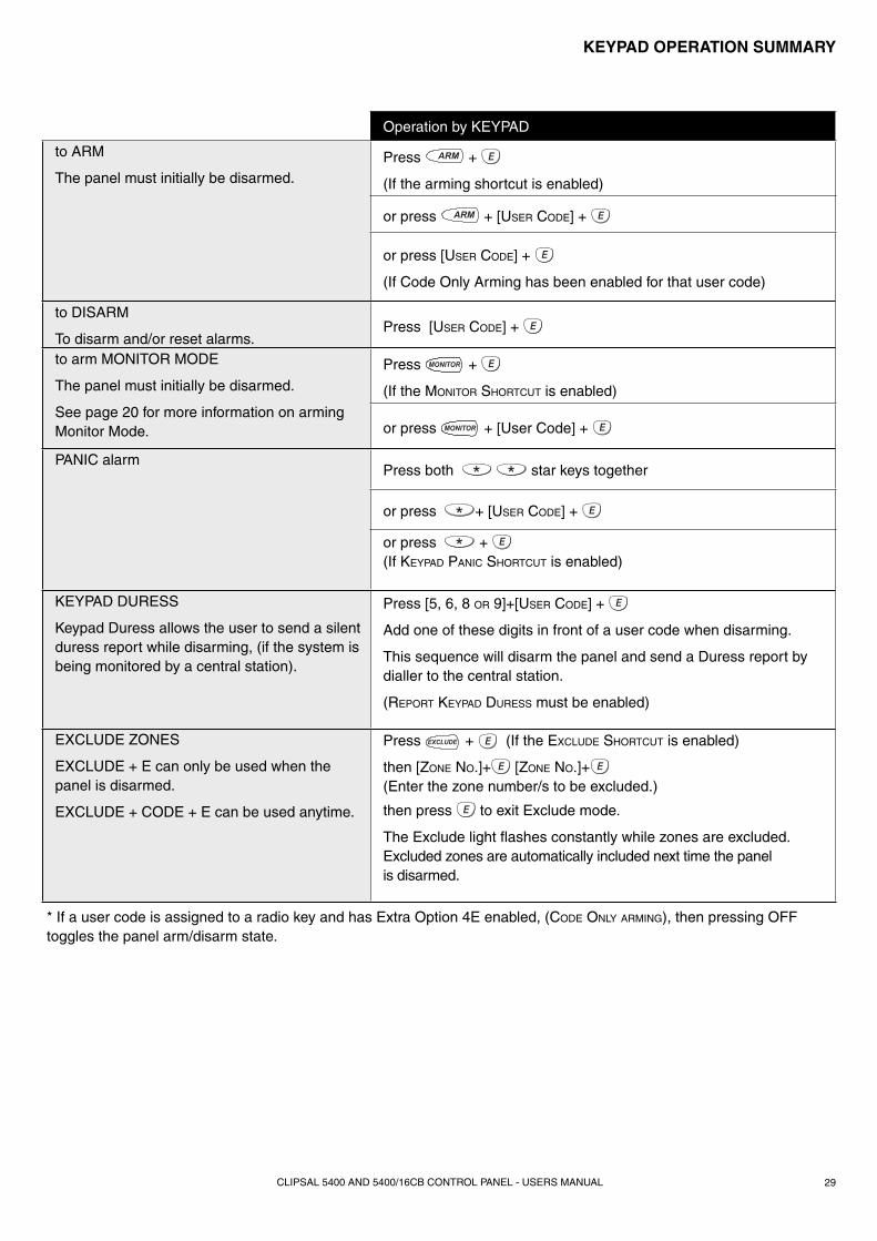
KEYPAD OPERATION SUMMARY
Operation by KEYPAD
to ARM
The panel must initially be disarmed.Press +
(If the arming shortcut is enabled)
or press + [USER CODE] +
or press [USER CODE] +
(If Code Only Arming has been enabled for that user code)
to DISARM
To disarm and/or reset alarms.Press [USER CODE] +
to arm MONITOR MODE
The panel must initially be disarmed.
See page 20 for more information on arming Monitor Mode.
Press +
(If the MONITOR SHORTCUT is enabled)
or press + [User Code] +
PANIC alarmPress both star keys together
or press + [USER CODE] +
or press + (If KEYPAD PANIC SHORTCUT is enabled)
KEYPAD DURESS
Keypad Duress allows the user to send a silent duress report while disarming, (if the system is being monitored by a central station).
Press [5, 6, 8 OR 9]+[USER CODE] +
Add one of these digits in front of a user code when disarming.
This sequence will disarm the panel and send a Duress report by dialler to the central station.
(REPORT KEYPAD DURESS must be enabled)
EXCLUDE ZONES
EXCLUDE + E can only be used when the panel is disarmed.
EXCLUDE + CODE + E can be used anytime.
Press + (If the EXCLUDE SHORTCUT is enabled)
then [ZONE NO.]+ [ZONE NO.]+ (Enter the zone number/s to be excluded.)
then press to exit Exclude mode.
The Exclude light fl ashes constantly while zones are excluded. Excluded zones are automatically included next time the panel is disarmed.
* If a user code is assigned to a radio key and has Extra Option 4E enabled, (CODE ONLY ARMING), then pressing OFF toggles the panel arm/disarm state.
CLIPSAL 5400 AND 5400/16CB CONTROL PANEL - USERS MANUAL 29
IS2-
004
10363485 Aug 9/05
CLI
PAD
V/1
0316
Product of Clipsal Integrated Sys tems Pty LtdMember of Clipsal Australia Holdings GroupABN 15 089 444 931
Head Offi ce12 Park Terrace, BowdenSouth Australia 5007
PO Box 103 HindmarshSouth Australia 5007Telephone (08) 8440 0500International +61 8 8440 0500
Facsimile (08) 8346 0845International +61 8 8346 0845
Internet www.clipsal.com/cisE-Mail [email protected]
CIS Technical Support Hotline:1300 722 247
National Customer Service Enquiries:1300 2025 25
National Customer Service Facsimile:1300 2025 56
International Enquiries
International Sales and MarketingTelephone +61 8 8269 0587Facsimile +61 8 8340 7350E-Mail [email protected]
New ZealandClipsal Industries (NZ) LtdTelephone +64 9 576 3403Facsimile +64 9 576 1015E-Mail headoffi [email protected]
Customer ServiceFree Facsimile (0508) 250 305Auckland/Mobile Phone (09) 572 0014Free Phone (0508) CLIPSAL 2547725
MalaysiaClipsal Integrated Systems (M) Sdn BhdUnit 3-2, Level 3, C P TowerNo.11, Jalan 16/11, Seksyen 16,46350 Petaling Jaya, Selangor, MalaysiaTelephone +60 3 7665 3555Facsimile +60 3 7665 3155E-Mail [email protected]
SingaporeClipsal Integrated Systems Pte Ltd5, Fourth Chin Bee Road619 699 SingaporeTelephone +65 6415 3232/3233Facsimile +65 6415 3289E-Mail [email protected]
Clipsal Integrated Systems Pty Ltd reserves the right to change spec i fi ca tions, modify designs and dis con tin ue items without incurring obligation and whilst every effort is made to ensure that descriptions, specifi cations and other in for ma tion in this catalogue are correct, no warranty is given in respect thereof and the company shall not be liable for any error therein.
You can fi nd this brochure and many others online in PDF format at: clipsal.comFollow the links off the home page or access the following page directly: clipsal.com/wat_lib_pdf.cfm
clipsal.com/cis
© Clipsal Integrated Systems Pty Ltd 2005.All rights reserved.
This material is copyright under Australian and international laws. Except as permitted under the relevant law, no part of this work may be reproduced by any process without prior written permission of and acknowledgement to Clipsal Integrated Systems Pty Ltd.
International Representatives
ChinaClipsal China LimitedTelephone +86 755 8237 5959
GreeceSchneider Electric AE
Telephone +30 69 4646 3200
Hong KongClipsal Integrated Systems (HK) LimitedTelephone +852 2487 0261
IndiaSchneider Electric India Pvt Ltd Telephone +91 11 5159 0000
IndonesiaPT Clipsal Graha NusaTelephone +62 21 630 6430
KoreaClipsal Korea Co. LtdTelephone +822 549 5550
PakistanClipsal Pakistan (Pvt) LtdTelephone +92 21 506 7278
PhilippinesClipsal Philippines Inc.Telephone +632 683 0275-78
South AfricaClipsal South Africa (Pty) LtdTelephone +27 11 314 5200
TaiwanClipsal (Taiwan) Co LtdTelephone +886 2 2558 3456
ThailandClipsal Thailand LtdTelephone +66 2 952 5338-42
United Arab EmiratesClipsal Middle EastTelephone +971 6 5570 777
United KingdomClipsal Integrated SystemsC/o Schneider ElectricTelephone +44 870 608 8 608
VietnamClipsal - VTECTelephone +848 856 3002