Embed Size (px)
Citation preview

LEXCOM HOME NETWORK INSTALLATION GUIDE

LexCom Home Network 3
Complete Flexibility 5
Planning 6
Product Overview 8
Installation 11
Termination 12
Mounting 13
Testing 14
Support 15
Certification Process 16
Connection to External Networks 17
Connection Examples 18
The LexCom Home Network Product Overview and Installation Guide has been compiled to assist installers and consultants with the understanding, design, installation and testing of the LexCom Home Network system. This document is however, not intended to be a comprehensive guide to all aspects of network cabling systems for residential buildings. The information contained in this document is advisory only. It is the responsibility of the installer to be adequately trained and aware of the relevant Australian standards and regulations pertaining to the installation practices and requirements for these types of home network products. PDL Industries Aust. Pty Ltd (hereafter referred to as "PDL") reserves the right to change specifications, designs or wording included in this document without notice and without obligation.

LexCom Home NetworkA Structured Network for the Home
LexCom Home Network is a unique and flexible network suitable for houses and apartments. It provides a universal installation for telephone, data and television connections. LexCom Home Network can, for instance, be connected to broadband internet, making it possible to use all the services offered by that technology throughout the home.
LexCom Home Network can be adapted for everything from small installations in individual houses to several installations in an apartment building or complex. In apartments, every dwelling can be equipped with its own LexCom Home Network connected to the incoming telephone / TV / data network of the building. Essentially, LexCom Home Network is the new home network for IT, communication and entertainment.
Built-in Flexibility
The network is a 'structured' installation in which a number of outlets of the same type are connected by cables to a distribution centre. Incoming cables for telephone, data, television, etc. are connected at the distribution centre, and patch leads are used to route the incoming signals to individual outlets around the home. This gives LexCom Home Network amazing flexibility, as it is simple to re-connect any outlet in any room to receive whichever incoming signal you require. A telephone outlet can easily be switched to receive TV, radio or internet signals within seconds.
The system uses the flexibility of open communication standards such as Ethernet to make it simple and easy to distribute signals around the home, and to change the function of outlets. LexCom Home Network is also compatible with other networks, and gives you the freedom to upgrade and replace modules as technology moves forward.
Easy to Install
LexCom Home Network is quick to install, thanks to its well thought out assembly methods. It has been developed to achieve high performance and reliability, with the best products on the market chosen and tested to ensure that the system works properly without compatibility problems. The network provides an infrastructure for three forms of media (data, telephone and television) all on the same cable, instead of a specific type of cable that would be needed for each medium if LexCom Home Network were not used.
3
© 2006 Copyright PDL Industries Aust. Pty Ltd. All rights reserved. PDL LexCom Home® is a registered trademark.

4
High Capacity
LexCom Home Network has been designed to satisfy present and future transmission speed demands. The system has a very high capacity, with a frequency range of up to 900 MHz, that exceeds the frequency currently used for free-to-air analogue and digital television. Its data components satisfy and exceed the requirements for Category 6, ensuring they will also meet future network speed demands. The data transfer speed depends on which data units are connected to the system. The standard data module offers speeds of 10/100 Mbit/s, and as the system is modular, it is easy to replace parts to obtain even higher speeds.
Design for the Future
Thanks to its great flexibility and high capacity, together with the easy installation of components and standardised open technology, LexCom Home Network is practically future proof. The system can handle the most common communication needs (telephone, television and data) and as it is easy to add new functions and services, LexCom Home Network can meet practically all communication needs in the future.

Complete FlexibilityThe LexCom Home Network system is so flexible that applicable equipment can be connected to any LexCom Home Network outlet in any room. This makes it easy to move equipment around the home and gives users greater freedom and options in the planning of their new home design.
All Functions in the Same Outlet
Each communication or entertainment device (whether it be a telephone, computer, TV, etc.) is linked to a standardised wall mounted outlet via a specially adapted connection.
Three types of connecting cords are provided for TV/video/radio, telephone and computer / network devices to be connected to the wall mounted outlets.
Easy to Change the Function of the Outlets
5
The distribution centre is a bit like a computer
patch panel. For every outlet in a room, there is a
corresponding port at the distribution centre, with the
same numbering.
A patch lead at the distribution centre connects the
outlet in the room to an active module (which can
be either the TV amplifier module or the telephone
module or the data module).
For example, to change a TV outlet in a room into a
computer outlet, simply unplug the patch lead from the
TV amplifier module and plug it into a spare port on
the data module. In the room, a computer can now be
connected to what used to be a television outlet.

PlanningLexCom Home Network is a structured network
LexCom Home Network is designed as a star network, which connects all the outlets to a central hub. Active modules are installed at the centre of the network to accept signal sources for telephone, TV and data. These elements are linked together at the specially developed distribution centre.From the distribution centre, the signals are distributed via the network to the individual wall outlets as required. The outlets can be connected by means of patch leads to precisely the signal source you need at a particular outlet in the home, i.e. data network, one or more telephone lines, radio / TV or other forms of video sources. This gives unprecedented flexibility.
Needs
It is important to define at an early stage what is required of the infrastructure. In a typical installation, up to 26 outlets can be connected to the distribution centre. If you need more outlets, you can upgrade to a high-density patch frame with ports for up to 40 outlets. Furthermore, future needs for new functions / applications can easily be met by changing or adding a module.
Cable Lengths
To maintain full capacity between the distribution centre and the wall outlets, no installation cable should be more than 40 metres long. To avoid over-driving the TV signal, no installation cable should be less than 8 metres long.
Positioning the Distribution Centre
Position the distribution centre as central as possible in order to achieve optimal cable lengths to the outlets (i.e. between 8 and 40 metres as mentioned above). The distribution centre should be located nearby an earth connection and an electric power socket outlet. This is because the distribution centre has to be earthed and the externally installed power supply transformer has to be connected to a power socket outlet. Position the distribution centre at a convenient height for operation and maintenance. The ambient temperature should be between ±0 and +40°C.
Positioning Outlets
Plan for at least two outlets in each room to meet future demands and to provide flexibility. Typically, there will be a telephone network outlet in rooms such as the hall, lounge and master bedroom, and an antenna outlet in the main living areas, bedrooms and the kitchen. A distribution centre with telephone, data and TV modules can be used for up to 26 outlets.
Other Considerations
Please refer to the sections on "Connection to External Networks" and "Connection Examples" in pages 17 to 23 for more details to be considered when connecting the LexCom Home Network installation to other systems and devices (both external networks and internal home appliances) that are not supplied by PDL.
6
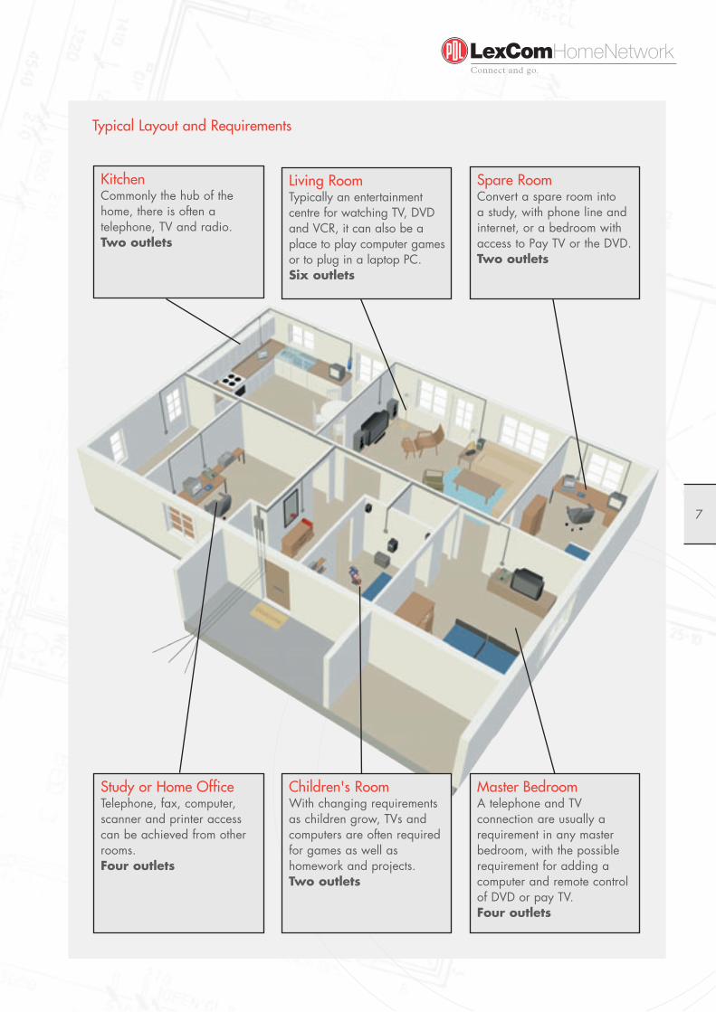
Typical Layout and Requirements
7
Master BedroomA telephone and TV connection are usually a requirement in any master bedroom, with the possible requirement for adding a computer and remote control of DVD or pay TV.Four outlets
Children's RoomWith changing requirements as children grow, TVs and computers are often required for games as well as homework and projects.Two outlets
Study or Home OfficeTelephone, fax, computer, scanner and printer access can be achieved from other rooms. Four outlets
KitchenCommonly the hub of the home, there is often a telephone, TV and radio.Two outlets
Living RoomTypically an entertainment centre for watching TV, DVD and VCR, it can also be a place to play computer games or to plug in a laptop PC. Six outlets
Spare RoomConvert a spare room into a study, with phone line and internet, or a bedroom with access to Pay TV or the DVD.Two outlets

8
Product OverviewLexCom Home Network is made up of a number of separate modules. This makes maintenance and upgrading easier as technology develops and new standards reach the market. All active modules are powered and they satisfy Australian electrical safety requirements.
The distribution centre is the heart of the LexCom Home Network system. It is made up of a distribution cabinet equipped with various modules that handle incoming signals (telephone, TV amplifier and data) and a patch frame comprising ports to which all outlets in the rooms are connected using RJ45 modular connection jacks. Upgrading and adding new functions is simply a matter of replacing or adding modules in the distribution centre.
Distribution Cabinet
The distribution cabinet is used to house centralised components of the LexCom Home Network system. It is available in two sizes (of height 22" and 14"), and can be either surface or flush mounted. The 22" distribution cabinet can accommodate up to 6 active modules (telephone, TV amplifier and data) and 26 patched out RJ45 jacks. The 14" distribution cabinet can accommodate up to 4 active modules and 16 jacks.
Cables entering the building are connected to the active modules in the distribution cabinet. Patch leads are then used to make further connections via the ports of the patch frame and the installation cables to the outlets in the rooms. Clear markings at both the distribution cabinet and the outlets make it easy to see how to connect the outlets.
Power Supply
A 12V DC Transformer is provided to supply power to the active modules. This power supply unit has to be installed outside the distribution cabinet.
Data Module
The data module is a switch with four ports to connect computers, printers and other hardware with network interfaces. The module also has an expansion port for connection to an external network such as a broadband internet network. The module supports Ethernet TCP/IP data rate of 10/100 Mbits/s.
Telephone Module
Incoming telephone lines are connected to the telephone module. The module can be used to distribute two incoming analogue lines. The module has eight ports for connection through to telephone and fax outlets. It also has several settings for grouping the various outlets and for changing priorities.

TV Amplifier Module
The TV amplifier module distributes television and radio signals throughout the network. The A110 module has an input port for the incoming antenna cable and six ports for patching through to the rooms. It also features an AV input port for connection to an AV modulator or PC player.
AV Combiner
The AV combiner allows 2 or 3 AV modulators or PC players to be connected into the AV input port of the A110 TV amplifier module. It combines the 3 AV signal inputs and forwards the combined result to the single output port, supporting infrared remote control on all devices as standard.
AV Modulators
Two options of AV modulators (either single channel or four channels) are available for the distribution of AV signals (DVD, VCR, security video cameras or Pay TV decoders) to multiple locations in the LexCom Home Network. The AV modulators convert composite video signals from these entertainment devices into TV channels and send them to the A110 TV amplifier module for further distribution. Both AV modulators support remote infrared control of the connected entertainment devices.
PC Player
The PC player has a built-in FM stereo modulator and has been designed for the distribution of MP3 music, internet radio, etc. from the sound card of a PC. It creates a FM radio channel for the sound signal connected to its input, allowing the stereo sound from any source to be transmitted into the LexCom Home Network via the A110 TV amplifier module. This signal can then be made available at any stereo receiver in the home.
Infrared Link
The infrared link, in conjunction with the A110 TV amplifier module, makes remote control of entertainment devices like a DVD, VCR or Pay TV decoder possible from all TV sets around the home.
The infrared link consists of component IR emitters and receivers. Receivers are located at the TV where the remote control is to be used. Emitters are located over the IR eye of the entertainment device to be controlled and are linked either to an AV modulator or directly to the A110 TV amplifier module.
Termination Plug
The termination plug provides a 100 ohm termination of the conducting twisted pair wires for radio/TV/audio-visual applications. It is a requirement that termination plugs are inserted into unused output ports of the TV amplifier module, to provide better response stability of the amplifier and minimise RF emissions. Any unused input of AV combiner and AV input of TV amplifier module should also be terminated by this plug to prevent noise from being introduced into the system.
9

10
Attenuator
The attenuator is a plug-in unit for outlets to compensate for short link problems with TV signals. Three options are offered, providing different levels of attenuation to the TV signals and thus simulating different lengths of the cable link.
Patch Leads
Patch leads are used only at the distribution centre to connect the incoming signals to the required outlet. These leads are available in either fully shielded (STP) used for only TV/video or unshielded (UTP) used for only telephone and data.
Connecting Cords
Three types of connecting cords are used to connect TV/radio, data and telecommunication devices to the wall mounted outlets.
TV/radio cord: Shielded, RJ45-coax, with built-in balun for impedance conversion from 100 ohm symmetrical to 75 ohm asymmetrical.Data cord: Shielded, RJ45-RJ45, Category 6. Telephone cord: Unshielded, RJ11-RJ45.
Installation Cable
Used for the fixed installation in the distribution network. The cable connects the outlets to the ports of the patch frame in the distribution centre. With its exceptional bandwidth and high signal capacity, the cable can handle all types of traffic (telephone, data, radio / TV). The copper cable is made up of individually screened 'twisted pair' wires with a common copper braid shield. Its outside diameter is 7.5mm. Supplied on 300 or 500 metre reels.
Modular Connection Jack
The modular connection jack (RJ45) is used at both the wall outlet and the patch frame in the distribution centre. It can allow very fast and easy termination of the installation cable without using any tool. Category 6 data performance and high quality TV transmission can be achieved with this jack.
Outlets
Outlets are located where needed. Normally, two or more outlets are installed in every room. The same type of outlet is used throughout the installation. The function of each outlet is controlled from the distribution centre. Different cords are used to connect different devices, depending on the function chosen for the outlet in question. Outlets are available in different colours to match PDL 600 series switches, electric socket outlets, dimmers, etc. The outlets are always fitted with RJ45 modular jacks.

11
InstallationThis section describes how LexCom Home Network should be installed. Detailed information about the components and how to install them is given in the documentation supplied with the products.
Before installation, it is important to prepare and plan so that you know where the outlets and the distribution centre are to be installed and which components the network will include.
Cable Installation
Cables must be run from all outlets to the distribution centre in accordance with the relevant Australian wiring standards. The number of cables must be equal to the number of outlets required in the particular room. The bending radius of installed cable must not be less than 25mm.
11
LexCom Home LexCom Home
1. Data module, with 4 ports for computer networks.
2. TV amplifier module, with 4 or 6 ports for TV connections.
3. Patch leads.4. Patch frame, with 26 ports for
connection to room outlets.
5. Telephone module, with 8 ports for telephone / fax / modem connections.
6. Distribution centre, where incoming cables from antenna, telephone and the building network are connected to the home network.
7. Shielded installation cable, 8 wires (4 twisted pairs).
8. Universal outlet with 2 or more jacks to be mounted in PDL's Wiring Accessory product.
Basic Components of the Home Network
1
5 67
8
4
32

12
TerminationThe RJ45 modular jack allows very fast and easy termination of the installation cable.
1. Cut and strip the cable as shown. 2. Pull back the shield over the insulated cable for at least 30mm.
3. I nsert the cable through the cover and upper part of the modular jack.
4. Insert the wire pairs into the correct slots in accordance with the colour coding as marked. Do not strip them. The slots penetrate the insulation to give a perfect contact.
6. Cut off the protruding wires flush with the modular jack.
7. Move the cover of the modular jack into place.
9. Cut off the excess shield.8. Firmly press the cover until it locks with a "click" sound, securing the cable and shield.
5. Firmly press on the upper part of the modular jack until it locks with a "click" sound
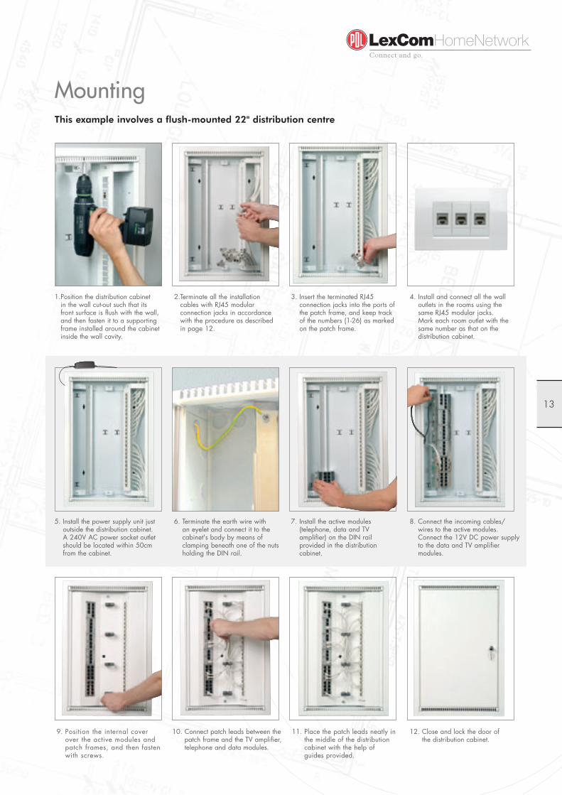
MountingThis example involves a flush-mounted 22" distribution centre
13
2. Terminate all the installation cables with RJ45 modular connection jacks in accordance with the procedure as described in page 12.
3. Insert the terminated RJ45 connection jacks into the ports of the patch frame, and keep track of the numbers (1-26) as marked on the patch frame.
4. Install and connect all the wall outlets in the rooms using the same RJ45 modular jacks. Mark each room outlet with the same number as that on the distribution cabinet.
7. Install the active modules (telephone, data and TV amplifier) on the DIN rail provided in the distribution cabinet.
8. Connect the incoming cables/ wires to the active modules. Connect the 12V DC power supply to the data and TV amplifier modules.
9. Position the internal cover over the active modules and patch frames, and then fasten with screws.
11. Place the patch leads neatly in the middle of the distribution cabinet with the help of guides provided.
10. Connect patch leads between the patch frame and the TV amplifier, telephone and data modules.
12. Close and lock the door of the distribution cabinet.
6. Terminate the earth wire with an eyelet and connect it to the cabinet's body by means of clamping beneath one of the nuts holding the DIN rail.
5. Install the power supply unit just outside the distribution cabinet. A 240V AC power socket outlet should be located within 50cm from the cabinet.
1. Position the distribution cabinet in the wall cut-out such that its front surface is flush with the wall, and then fasten it to a supporting frame installed around the cabinet inside the wall cavity.

14
Testing When a LexCom Home Network installation is completed, it must be tested to ensure that all connections have been correctly made and installation requirements satisfied, before it can be given the PDL LexCom Home Network extended warranty.
A LexCom Home Network installation must be tested to confirm that all permanent links meet the performance requirements in compliance with at least Class E as specified in AS / NZS 3080:2002 (and ISO 11801 Ed2).
Measurement of the network can be performed with Level 3 hand-held field testers that are capable of recording and storing the required data for the test reports.
Measurement of the wire map, return loss, attenuation / cable lengths and NEXT compliant with the Category 6 Permanent Link standard shall be the minimum requirement.
Testing of TV/Video Network
The LexCom Home Network installation must also be tested to ensure adequate TV/video quality at every outlet. This testing should be performed with a RF field strength meter.
As a minimum requirement, a video test signal (from the LexCom Home Network AV Modulator or equivalent) should be injected into the system, and level measurements should be taken at the shortest and longest cable runs. The strength of these test signals need to be measured and documented (should be within the range of 60 - 80 dB microvolt).
It is recommended that an external TV antenna is already properly installed (for optimal reception of terrestrial TV signal) and connected to the LexCom Home Network system at the time of testing. The signal strength of all the TV channels should be within the range of 60 - 80 dB microvolt throughout the home. The difference in signal strength between the strongest and weakest TV channels at any outlet should not exceed 12 dB microvolt.
The LexCom Home Network installation amplifies and distributes the TV signal inside the home, but does not improve the quality of the incoming TV antenna signal. If the incoming TV antenna signal results in poor TV reception (e.g. due to weak signal strength or too much interference), this problem should be checked and rectified by a TV antenna installation specialist.

SupportThere is a big difference between installing high-speed data networks and conventional electrical and telecommunication installations. Capacity will be reduced if the installation work is not done properly, e.g. cables must run in smooth curves at corners, they must not be strapped too tight, and so on. Therefore it is important for installers to have sufficient theoretical and practical knowledge about networks.
Training
PDL provides training courses for installers and consultants to ensure professional installation and technical support of LexCom Home Network. These training courses increase the competitiveness of installers and consultants as they can offer their customers the latest technology that is available today for home networking solutions.Installers who sign up for the PDL LexCom Home Network training courses will have prior knowledge and experience working with networks. Both theoretical and practical exercises will be included in the training. Everyone who completes a training course will be authorised to install LexCom Home Network systems (refer to Authorised Installer application document for more details).
Certification and Warranty
PDL offers certification of each LexCom Home Network installation that has the necessary details and documentation submitted to PDL. This certification provides an assurance to the home owner that the completed installation satisfies the requirements and relevant standards for a LexCom Home Network system.
Together with the certification of each LexCom Home Network system that is properly installed and fully tested, PDL provides a warranty assuring a high level of performance. This allows an Authorised Installer to provide the home owner with a PDL warranty covering: • 15 years for the passive components of the LexCom Home Network
fixed installation comprising the distribution cabinet, installation cables, connection jacks and wall-mounted outlets.
• 2 years for the active modules, components and products of the LexCom Home Network system.
The warranty assures that products supplied by PDL are free from defects in material and workmanship for the applicable period starting from the date of installation, subject to normal use and service of the products.The above warranty description is only a brief note and is therefore not exhaustive. For more comprehensive details of this warranty, please refer to the PDL LexCom Home Network Warranty document.
15

Certification ProcessThe process that needs to be undertaken for the installation, testing and certification of the LexCom Home Network system is summarised as follows:
16
Installation of the LexCom Home
Network system is performed by an
authorised / trained installer.• Installer - name, company, address• Home owner - address
All products used in the LexCom
Home Network system have been
supplied by PDL. • Itemised list of products installed (eg.
copy of invoice or bill of materials)
Measurements and testing of
completed installation are made in
accordance with PDL's requirements.• Report confirming "PASS" for all
tested components of the LexCom
Home Network installation.
Details and documentation of the completed installation and affirmative test results are sent to PDL.
PDL issues the LexCom Home Network Warranty Certificate
that is to be sent by the Authorised Installer to the home
owner at the address of the installation.
+Required Documentation
Required Documentation
✓YES
Required Documentation
✓YES
+
✓YES
✓YES

17Data (broadband), telephone and television signals supplied to the building by companies that build and own broadband networks can be connected to the LexCom Home Network system via the main building infrastructure.
Building networks distribute television, telephone and data to every home.
Connection to External NetworksIn an apartment building or complex, it is very common for a master telephone, MATV and data network to be installed in the building to distribute these external services to the individual apartment units. Each apartment can then have an internal LexCom Home Network system that connects to the master/external network via a distribution centre.
An example is the connection of a broadband internet network to the LexCom Home Network system. Here, additional features and devices such as firewalls, routers and modems should be carefully considered and included to ensure security and proper communication between the external network and the LexCom Home Network system.
This installation guide does not cover the planning and installation of external network interconnections that may be provided separately by others. There are several organisations in the market offering services for the integration of such networks with one another.
The distribution centre in LexCom Home Network is connected via installation cables in a star configuration to outlets in every room for connecting TVs, telephones and computers.
TelevisionTelephoneData

18
Distribution of Telecoms, TV and DataLexCom Home Network gives an infrastructure for several types of media on a network. In this example, incoming signals for data, telephone and television are connected to the active modules of the distribution centre and patched to the required outlets.
Connection Examples
Simple TV Antenna DistributionHere, LexCom Home Network connects all TV sets to the TV antenna. In addition, a radio is connected to the antenna system using the female adaptor supplied.
Note: In the following
connection examples, all
systems and devices that
are not part of the
LexCom Home Network
installation, are to be
procured by the home
owner or installer from
other suppliers and/or
service providers.

19
Network with Computers and Printers and a Connection to an External Network (e.g. Broadband)In this example, LexCom Home Network is used to set up an internal data network of computers and a shared printer. The outlets are patched to the data module of the distribution centre to allow communication between these outlets. Connection is also made to an external network, e.g. broadband or a permanent internet connection. This internet service is then also available at all outlets connected to the data module.
Infrared (IR) LinkThis example shows a TV antenna connected to the A110 TV amplifier module. In this installation, there is an AV modulator which can accept signals from four video sources (video, DVD, etc.). These video sources can be controlled from all rooms via IR receivers. The AV modulator must be connected to the AV link port on the A110 TV amplifier module via an outlet and a patch module. All six outlets on the TV amplifier module can receive IR control signals. IR control signals are always sent on the AV port and IR output of the TV amplifier module.

20
ROOM 1
AV LinkLexCom Home Network is connected to a TV antenna and two satellite receivers. At the same time, there are DVD and video devices. The TV antenna is connected directly to the A110 TV amplifier module. Satellite receivers and video / DVD devices are connected to an AV modulator which is located at the main TV set. The main TV set can still be connected directly to a satellite receiver or video / DVD devices via a scart, RCA or S-Video cord if required. These signals can be mixed and sent to all outlets when the AV modulator is connected to the AV link port on the TV amplifier module. It is also possible to control satellite receivers / video devices from all TV sets via an IR link in the TV amplifier module and the AV modulator.
Free-to-air Digital TVLexCom Home Network can be connected to high definition digital TV. This example shows the connection arrangement with digital TV and set-top box. TV programs from the set-top box can be viewed on other TV sets via the AV link. The set-top box can also be controlled from other TV sets if the IR system is connected to IR link.

21
Satellite / Pay TVLexCom Home Network can be connected to both terrestrial TV (via antenna) and Pay TV (via satellite dish), with the satellite receiver located close to the main wide screen TV set. By connecting an AV modulator (which is linked to the AV link port on TV amplifier module A110 via the wall outlet and patch module), other TV sets can show both terrestrial TV and the channel to which the satellite receiver is set. The satellite receiver can also be operated and controlled from all TV sets via IR link in the TV amplifier module and AV modulator.
Satellite / Pay TV, with Return Traffic LexCom Home Network can be connected to Satellite / Pay TV with possibility to communicate with the Pay TV system operator. The return traffic in this example goes from the satellite receiver via the LexCom Home Network's telephone module to the Pay TV system operator. An application of return traffic is 'pay per view'. Pay TV programs can be viewed on other TV sets via the AV link. The satellite receiver can also be controlled from other TV sets if the IR system is connected to IR link.

22
Cable TV with Internet Connection This example shows a connection providing both cable TV and internet services. A splitter is used to separate the incoming data and cable TV signals. The data signals are fed via the cable modem/router to the LexCom Home Network's data module to provide internet service to all the outlets connected to this data module. The cable TV signals are fed to the cable TV decoder / set-top box located close to the main wide-screen TV set. With the LexCom Home Network's AV link, other TV sets can show both terrestrial TV and the channel to which the cable TV decoder is set. The cable TV decoder can also be operated and controlled from all TV sets with the IR link.
ADSL Incoming ADSL lines are terminated by the system operator at the splitter. The analogue port of the splitter must be connected to the telephone module, e.g. the T100. The ADSL port of the splitter must be connected via the ADSL router to the data module (S100 data switch). The computers can now surf the internet simultaneously using shared internet access via the ADSL router. At the same time, the analogue port can be used for conventional telephones. The splitter and ADSL router are both obtained from the telecommunication service provider.

23
CCTV Camera Monitoring In the example, LexCom Home Network is used to transfer signals from the CCTV cameras to all TV sets connected to the system. The signal from the video camera is placed on a channel and can be viewed by selecting that channel on the TV set. The camera and AV modulator can be moved and connected to a spare outlet on the system.
PC PlayerThe PC player is the FM stereo modulator for LexCom Home Network. It is used when there is an audio source that is not centrally located and where the signal from this source is required to be distributed via LexCom Home Network to the stereo and hi-fi installations in the home. In this example, the computer receives broadband internet radio, which goes from the computer's sound card to the PC Player. The PC player modulates the frequency to a pre-set selectable FM channel, and then send the modulated signal to the AV input of the A110 TV amplifier module. Any of the hi-fi stereo amplifiers can then receive the signal and play it over the loudspeakers. Similarly, MP3 audio stored in the computer can be played back on any of the sound systems in the home.

SALES & CUSTOMER SERVICETel: 1300 PDL COM (1300 735 266)
Fax: 1300 PDL FAX (1300 735 329)
www.pdl.com.au
www.lexcom.com.au
PDL INDUSTRIES AUSTRALIA PTY LTDABN 31 006 147 351
Postal Address:
Locked Bag 5500
Baulkham Hills Business Centre
NSW 2153 Australia
Tel: +61 (2) 9851 2666
Fax: +61 (2) 9851 2695
As standards and specifi cations change from time to time, please ask for confi rmation of the information given in this publication.
PD
L030706