Embed Size (px)
Citation preview

1
Home Building Manual 2014 Draft (22 January, 2014)
2
Introduction
The Housing Consumer Protection Measures Act of 1999 requires the NHBRC to establish a fund for the purpose of providing assistance to housing consumers where a home builder fails to rectify major structural defects or a roof leak attributable to workmanship, design or materials which has manifested itself within 5 years or 12 months from the date of occupation, respectively. The Minister is required to prescribe Technical Requirements relating to the warranty scheme. The NHBRC is required to publish a Home Building Manual which contains the Technical Requirements prescribed by the Minister and guidelines established by the NHBRC to satisfy such requirements. Registered Home builders are required to comply with the provisions of the Home Building Manual and to rectify at their own cost major structural defects or roof leakage in a home caused by the non-compliance with the scheme requirements and occurring within a stipulated period. The Act does not exempt a person from any provision of the National Building Regulations and Building Standards Act, 1977. Although there are many similarities in the approach between the National Building Regulations and the NHBRC Technical Requirements, the onus is on the owner of a building to satisfy requirements in the case of the former and on the home builder in the case of the latter. Part A of the Home Building Manual reproduces the NHBRC’s Technical Requirements which were published in Government Gazette no………. These NHBRC Technical Requirements: 1) define the categories of dwelling units that are excluded and excluded from the definition of a
home and the structures which are included in the definition of a home;
2) establish both performance descriptions and performance parameters for structural strength and stability, serviceability, materials, behaviour in fire, drainage and storm water management and water installations in relation to the warranty scheme as indicated below;
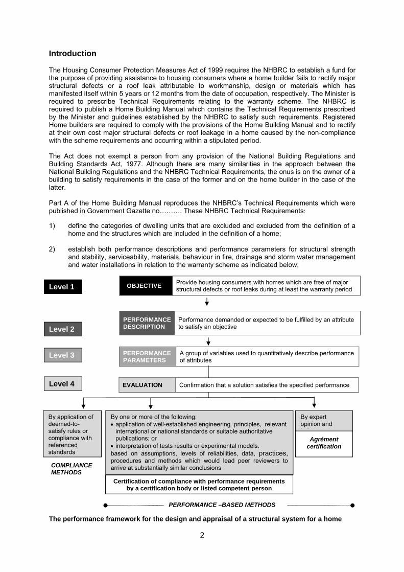
The performance framework for the design and appraisal of a structural system for a home
Level 1
Level 2
Level 3
Level 4
OBJECTIVE Provide housing consumers with homes which are free of major structural defects or roof leaks during at least the warranty period
PERFORMANCE DESCRIPTION
Performance demanded or expected to be fulfilled by an attribute to satisfy an objective
PERFORMANCE PARAMETERS
A group of variables used to quantitatively describe performance of attributes
By application of deemed-to-satisfy rules or compliance with referenced standards
By one or more of the following: application of well-established engineering principles, relevant
international or national standards or suitable authoritative publications; or
interpretation of tests results or experimental models. based on assumptions, levels of reliabilities, data, practices, procedures and methods which would lead peer reviewers to arrive at substantially similar conclusions
By expert opinion and j d t
COMPLIANCE METHODS
PERFORMANCE –BASED METHODS
Certification of compliance with performance requirements by a certification body or listed competent person
EVALUATION Confirmation that a solution satisfies the specified performance
Agrément certification

3
3) establish requirements for geotechnical investigations to ascertain the design parameters for the foundations of homes and the permitted development of dolomite land for homes;
4) establish procedures for the in principal acceptance of greenfield housing
developments for enrolment with or without conditions; 5) establish the framework for the recognition and operation of certification schemes; 6) establish procedures for the admission to and removal from a Council list of competent
persons. Part B of the Home Building Manual establishes the manner in which the NHBRC Technical Requirements can be satisfied. It: a) contains definitions and references to standard in additional to those contained in the
NHBRC Technical Requirements;
b) establishes compliance methods to satisfy the performance requirements established in the NHBRC technical requirements i.e. by applying deemed-to-satisfy rules or complying with identified standards;
c) establishes specific procedures for satisfying performance requirements by means of
performance based methods i.e. though certification by a certification body, a listed competent person or Agrément South Africa; and
d) establishing requirements for geotechnical investigations, the development of dolomite
land and indemnity insurance. The Concise Guide to the Home Building Manual, which is published separately, not only explains the Home Building Manual but also locates the manual in the broader context of sustainable human settlements with cross references to essential publications such as the National Housing Code, the Housing Project Process Guide (2009) and the Human Settlements Red Book.
4
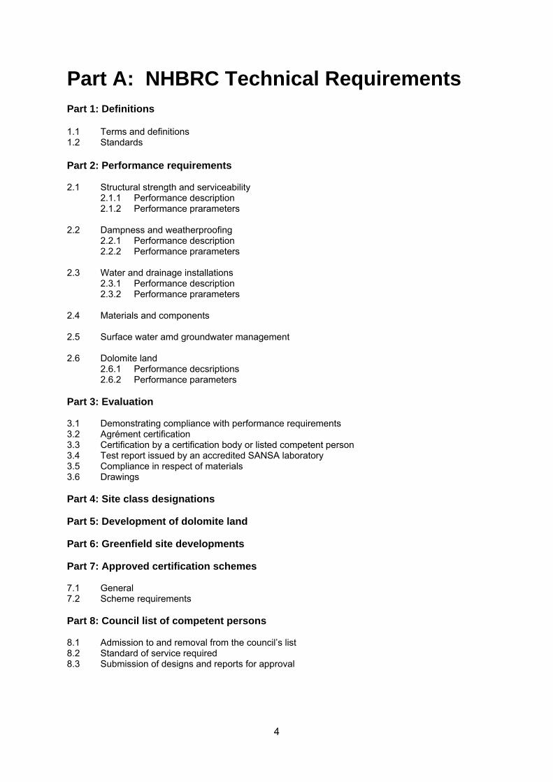
Part A: NHBRC Technical Requirements Part 1: Definitions 1.1 Terms and definitions 1.2 Standards Part 2: Performance requirements 2.1 Structural strength and serviceability
2.1.1 Performance description 2.1.2 Performance prarameters
2.2 Dampness and weatherproofing
2.2.1 Performance description 2.2.2 Performance prarameters
2.3 Water and drainage installations
2.3.1 Performance description 2.3.2 Performance prarameters
2.4 Materials and components 2.5 Surface water amd groundwater management 2.6 Dolomite land 2.6.1 Performance decsriptions 2.6.2 Performance parameters Part 3: Evaluation 3.1 Demonstrating compliance with performance requirements 3.2 Agrément certification 3.3 Certification by a certification body or listed competent person 3.4 Test report issued by an accredited SANSA laboratory 3.5 Compliance in respect of materials 3.6 Drawings Part 4: Site class designations Part 5: Development of dolomite land Part 6: Greenfield site developments Part 7: Approved certification schemes 7.1 General 7.2 Scheme requirements Part 8: Council list of competent persons 8.1 Admission to and removal from the council’s list 8.2 Standard of service required 8.3 Submission of designs and reports for approval
5
Insert NHBRC Technical requirements in here
6
Part B: Satisfying the NHBRC’s Technical Requirements
ContentsPart A: NHBRC Technical Requirements .............................................................................. 3
Part 1: Definitions and standards ............................................................................................ 7
1.1 Terms and definitions ............................................................................................... 7
1.2 Standards ................................................................................................................. 7
Part 2: Compliance methods ................................................................................................... 9
2.1 General ..................................................................................................................... 9
2.2 Structural strength and serviceability ........................................................................ 9
2.1.1 Foundations and floors ...................................................................................... 9
2.1.2 Roofs ............................................................................................................... 10
2.1.3 Walls ................................................................................................................ 10
2.2 Dampness and weatherproofing ............................................................................. 10
2.3 Water and drainage installations ............................................................................ 11
2.4 Materials and components ....................................... Error! Bookmark not defined.
2.5 Surface water amd groundwater management ...................................................... 11
2.6 Dolomite land ............................................................ Error! Bookmark not defined.
Part 3: Performance based methods .................................................................................... 12
7
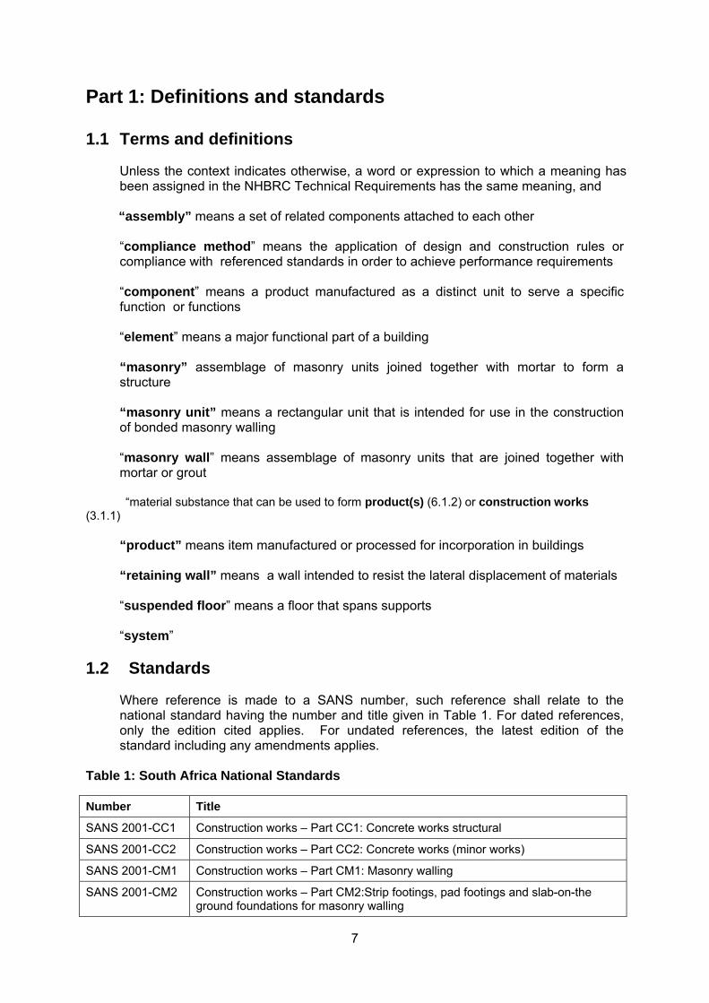
Part 1: Definitions and standards 1.1 Terms and definitions
Unless the context indicates otherwise, a word or expression to which a meaning has been assigned in the NHBRC Technical Requirements has the same meaning, and
“assembly” means a set of related components attached to each other “compliance method” means the application of design and construction rules or compliance with referenced standards in order to achieve performance requirements “component” means a product manufactured as a distinct unit to serve a specific function or functions “element” means a major functional part of a building “masonry” assemblage of masonry units joined together with mortar to form a structure “masonry unit” means a rectangular unit that is intended for use in the construction of bonded masonry walling “masonry wall” means assemblage of masonry units that are joined together with mortar or grout
“material substance that can be used to form product(s) (6.1.2) or construction works (3.1.1)
“product” means item manufactured or processed for incorporation in buildings “retaining wall” means a wall intended to resist the lateral displacement of materials “suspended floor” means a floor that spans supports “system”
1.2 Standards Where reference is made to a SANS number, such reference shall relate to the national standard having the number and title given in Table 1. For dated references, only the edition cited applies. For undated references, the latest edition of the standard including any amendments applies.
Table 1: South Africa National Standards
Number Title
SANS 2001-CC1 Construction works – Part CC1: Concrete works structural
SANS 2001-CC2 Construction works – Part CC2: Concrete works (minor works)
SANS 2001-CM1 Construction works – Part CM1: Masonry walling
SANS 2001-CM2 Construction works – Part CM2:Strip footings, pad footings and slab-on-the ground foundations for masonry walling
8
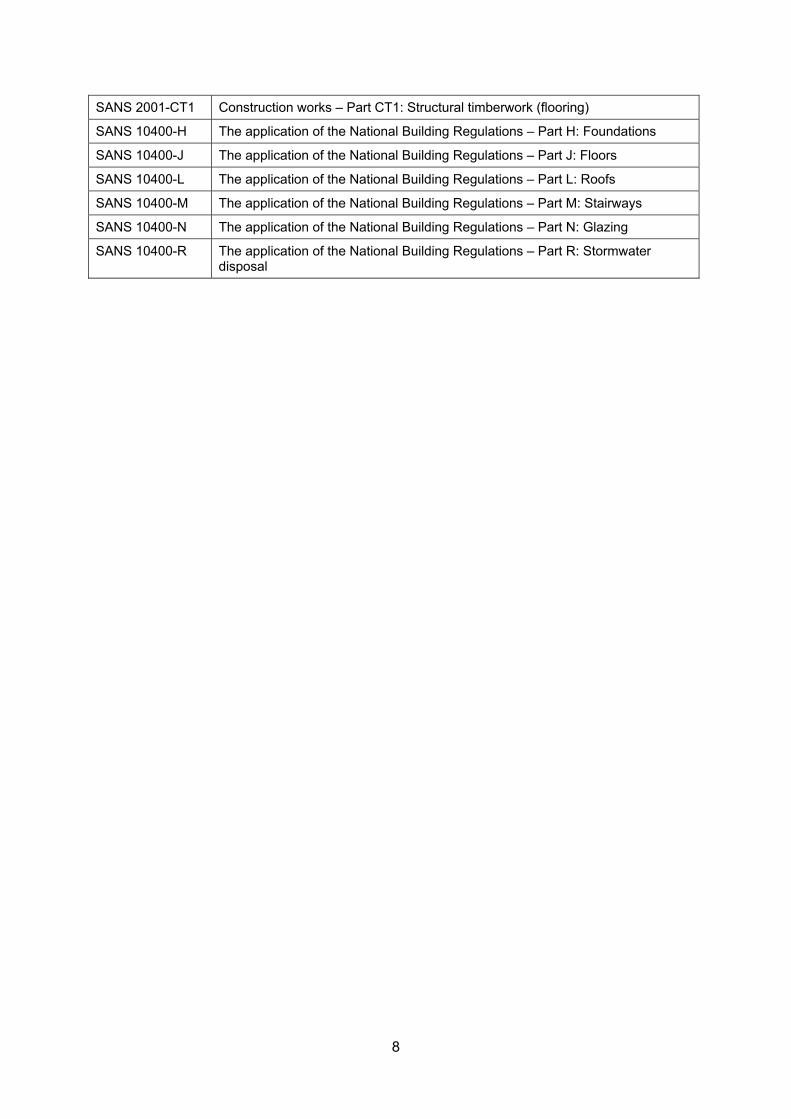
SANS 2001-CT1 Construction works – Part CT1: Structural timberwork (flooring)
SANS 10400-H The application of the National Building Regulations – Part H: Foundations
SANS 10400-J The application of the National Building Regulations – Part J: Floors
SANS 10400-L The application of the National Building Regulations – Part L: Roofs
SANS 10400-M The application of the National Building Regulations – Part M: Stairways
SANS 10400-N The application of the National Building Regulations – Part N: Glazing
SANS 10400-R The application of the National Building Regulations – Part R: Stormwater disposal
9
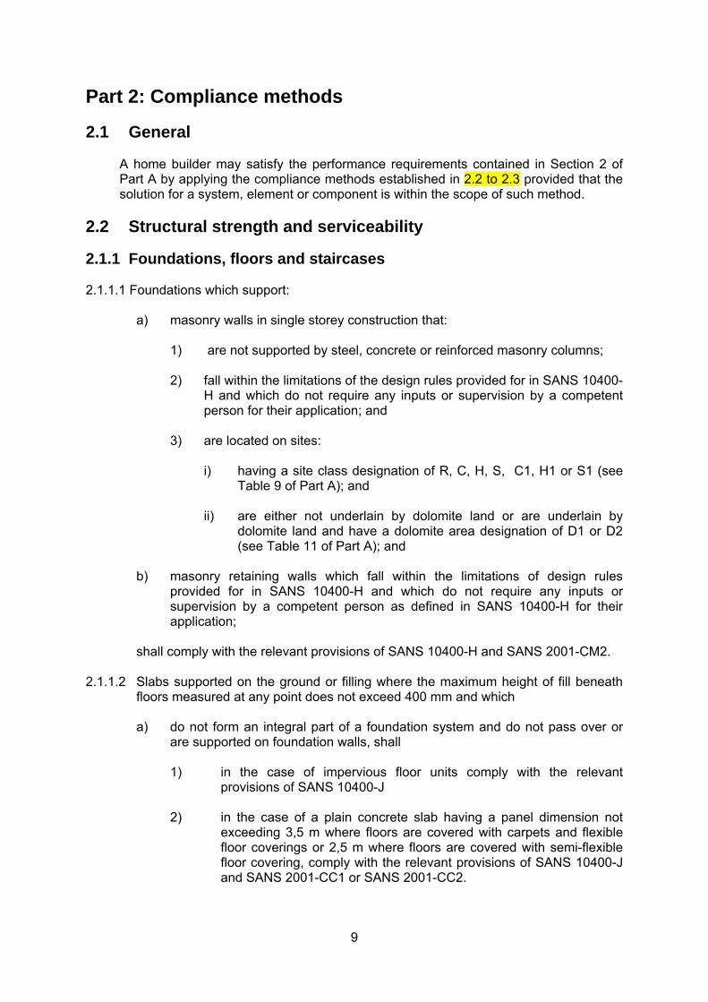
Part 2: Compliance methods
2.1 General
A home builder may satisfy the performance requirements contained in Section 2 of Part A by applying the compliance methods established in 2.2 to 2.3 provided that the solution for a system, element or component is within the scope of such method.
2.2 Structural strength and serviceability
2.1.1 Foundations, floors and staircases 2.1.1.1 Foundations which support:
a) masonry walls in single storey construction that:
1) are not supported by steel, concrete or reinforced masonry columns; 2) fall within the limitations of the design rules provided for in SANS 10400-
H and which do not require any inputs or supervision by a competent person for their application; and
3) are located on sites:
i) having a site class designation of R, C, H, S, C1, H1 or S1 (see
Table 9 of Part A); and ii) are either not underlain by dolomite land or are underlain by
dolomite land and have a dolomite area designation of D1 or D2 (see Table 11 of Part A); and
b) masonry retaining walls which fall within the limitations of design rules
provided for in SANS 10400-H and which do not require any inputs or supervision by a competent person as defined in SANS 10400-H for their application;
shall comply with the relevant provisions of SANS 10400-H and SANS 2001-CM2.
2.1.1.2 Slabs supported on the ground or filling where the maximum height of fill beneath
floors measured at any point does not exceed 400 mm and which
a) do not form an integral part of a foundation system and do not pass over or are supported on foundation walls, shall
1) in the case of impervious floor units comply with the relevant
provisions of SANS 10400-J
2) in the case of a plain concrete slab having a panel dimension not exceeding 3,5 m where floors are covered with carpets and flexible floor coverings or 2,5 m where floors are covered with semi-flexible floor covering, comply with the relevant provisions of SANS 10400-J and SANS 2001-CC1 or SANS 2001-CC2.
10
b) form an integral part of a foundation system, have a panel dimension in excess of that described in 2.1.1.2a) or pass over or are supported on foundation walls shall comply with the provisions of SANS 10400-H and SANS 2001-CM2.
2.1.1.3 Suspended timber floors that are not exposed to the elements shall comply with the
relevant provisions of SANS 10400-J and SANS 2001-CT1. 2.1.1.4 Masonry stairways in single and double storey homes shall comply with the relevant
provisions of SANS 10400-M and SANS 2001-CM1 and SANS 2001-CC1 or SANS 2001-CC2.
2.1.1.5 Timber stairways in single and double storey homes shall comply with the relevant
provisions of SANS 10400-M. 2.1.2 Walls 2.1.2.1 Masonry walls that fall within the limitations of design rules provided in SANS
10400-K shall comply with the relevant provisions of SANS 10400-K. 2.1.2.2 Glazing in external and internal walls shall be in accordance with the relevant
provisions of SANS 10400-N and be installed in a frame in accordance with either the requirements of SANS 2001-CG1 or a suitable method described in SANS 10137.
2.1.3 Roof and ceiling assemblies 2.1.3.1 Roof and ceiling assemblies that fall within the limitations of design rules provided in
SANS 10400-L shall comply with the relevant provisions of SANS 10400-L. (skylights ?) (thatch roofs}
2.2 Dampness and weatherproofing 2.2.1 The provisions in masonry walls to provide resistance to moisture penetrating from
the outside of a home shall be in accordance with the relevant provisions of SANS 10400-K.
2.2.2 The provisions in concrete floors and impervious floors laid on the ground to provide
resistance to moisture penetrating from the outside of a home shall be in accordance with the relevant provisions of SANS 10400-J.
2.2.3 The provisions of roofs to resist rain penetration and to avoid the accumulation of
rainwater thereon shall be in accordance with the relevant provisions of SANS 10400-L.
2.2.4 Ridges, valleys and flashings shall be in accordance with the relevant provisions of
SANS 10400-L and SANS 10400-R. (condenation thermal software programme of Agrement South Africa)?
11
2.3 Water and drainage installations
2.3.1 Drainage installations shall be designed in accrodance with the provisions of SANS 10400-P and installed in accrodance with the provisions of Annexure 1.
2.3.2 Water installations shall be in accordance with the provisions of Annexure 2 (need to
develop a specification based on SANS 10252-1). 2.3.3 Conervancy tanks, sceptic tanks and french drains shall comply with the relevant
requirements of SANS 10400-Q.
2.4 Surface water and groundwater management (Need to establish basic requirements for a house on its own plot)
12
Part 3: Performance based methods
3.1 General 3.1.1 A home builder shall where a solution for a system, element or component falls
outside the scope of a compliance method or the home builder chooses not to adopt a solution in accordance with a compliance method either: a) appoint a listed competent person or a certification body to demonstrate
that a solution for a system, element or component satisfies the performance requirements established in Part A; or
b) obtain Agrément certification; or
c) a combination of a) and b) above. . 3.1.2 A home builder shall obtain Agrément certification for a solution where a certification
body or a listed competent person cannot demonstrate compliance with performance requirements by means of one or more of the following:
a) application of well-established engineering principles, relevant international or national standards or suitable authoritative publications; or
b) interpretation of tests results or experimental models
based on assumptions, levels of reliabilities, data, practices, procedures and methods which would lead peer reviewers to arrive at substantially similar conclusions.
2.1.3 Listed competent persons and certification bodies may not certify that a component
or element of a home complies with the requirements of Part A unless they are satisfied that: a) the dampness and weatherproofing performance requirements and the
foundation system requirements as a whole are satisfied in the case of the certification of a foundation;
b) the dampness and weatherproofing performance requirements, fire resistance requirements for walls as well as the stability of the structure as a whole are satisfied in the case of a wall;
c) the dampness and weatherproofing performance requirements and fire safety
requirements for floors as well as the structural performance requirements at the interface between the floor and the wall are satisfied in the case of a floor;
d) the structural performance requirements at the interface between the floor and
the wall are satisfied in the case of a floor; and
e) the structural solution for the roof assemblies is compatible with associated solution for the dampness and weatherproofing performance requirements.
2.1.4 The home builder shall upload the certificates for each on the website
13
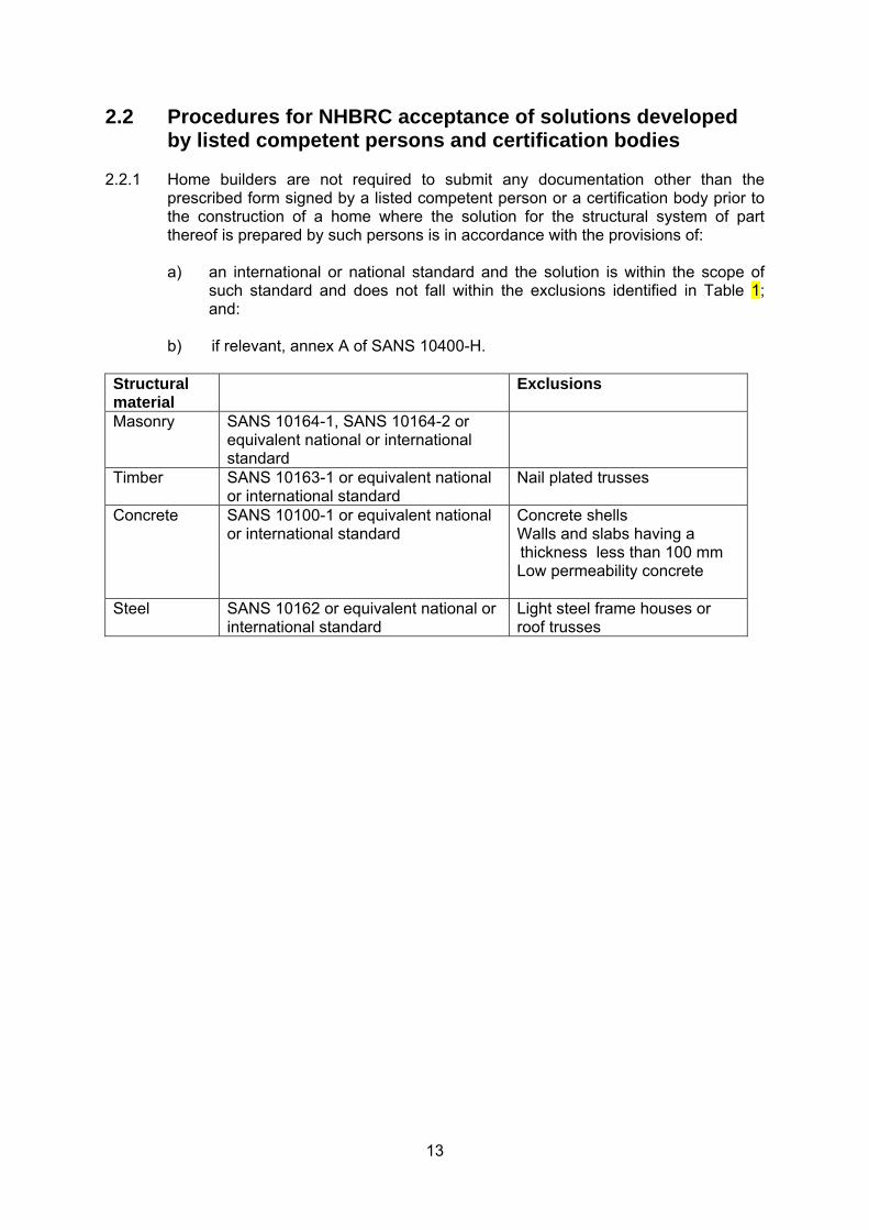
2.2 Procedures for NHBRC acceptance of solutions developed by listed competent persons and certification bodies
2.2.1 Home builders are not required to submit any documentation other than the
prescribed form signed by a listed competent person or a certification body prior to the construction of a home where the solution for the structural system of part thereof is prepared by such persons is in accordance with the provisions of:
a) an international or national standard and the solution is within the scope of
such standard and does not fall within the exclusions identified in Table 1; and:
b) if relevant, annex A of SANS 10400-H.
Structural material
Exclusions
Masonry SANS 10164-1, SANS 10164-2 or equivalent national or international standard
Timber SANS 10163-1 or equivalent national or international standard
Nail plated trusses
Concrete SANS 10100-1 or equivalent national or international standard
Concrete shells Walls and slabs having a thickness less than 100 mm Low permeability concrete
Steel SANS 10162 or equivalent national or international standard
Light steel frame houses or roof trusses
14
Part 4: Requirements for geotechnical investigations
4.1 Certification of compliance (develop content)
4.2 Modifications and additional requirements to SANS 634
4.2.1 The provisions of SANS 634:2012 are amended as follows:
a) replace 3.1 with the following: acceptable acceptable to the Council b) delete note below 3.17 c) replace 3.18 with the following:
investigator a certification body or a listed competent person appointed by the home builder
d) replace “competent person” in 3.20, 4.1.3 and 4.1.7 with “investigator” e) replace 4.1.5 with the following:
4.1.5 Site underlain by dolomites shall comply with the relevant requirements of Parts A and B.
f) replace 4.3.1 c) and d) with the following:
c) broadly classify the land which is to be developed in accordance with
the site class designations in accordance with the provisions of Table 9 of Part A;
d) determine the suitability of dolomite land for housing developments and
designate any dolomite land in accordance with the requirements of Table 10 of Part A;
g) replace 4.3.2.4 h) with the following:
h) broadly classify the land which is to be developed in accordance with
the site class designations for single-storey and double-storey type 1 masonry homes given in Table 9 of Part A
h) replace 4.4.1 b) with the following:
b) confirm the inherent hazard class (see Table 10 of Part A) and confirm
that the mandatory precautions outlined in the phase 1 report have been observed.
15
4.2.2 The phase 1 detailed investigation report described in SANS 634 shall in the case of a subsidy housing scheme implemented in accordance with the provisions of the Housing Act of 1997, (Act No. 107 of 1997) include:
a) an assessment of the suitability of the material in the upper 1,5 m of the site
for excavation by hand; b) a description of the material likely to be encountered in service trenches;
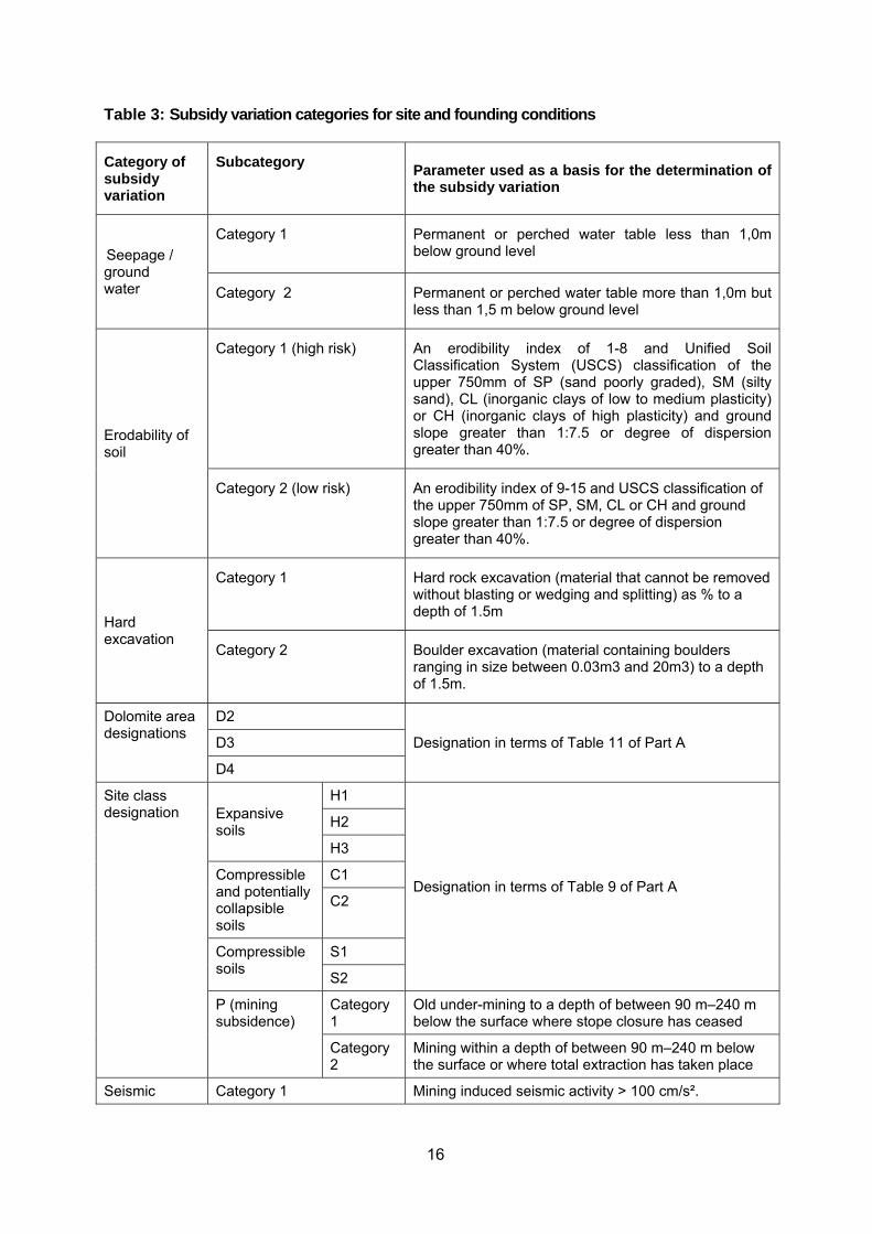
c) the identification of relevant parameters listed in Table 3 which are required to
establish subsidy variations and the extent of such parameters across the greenfield site development; and
d) recommendations, if any, on the installation of subsurface drains.
16
Table 3: Subsidy variation categories for site and founding conditions
Category of subsidy variation
Subcategory Parameter used as a basis for the determination of the subsidy variation
Seepage / ground water
Category 1 Permanent or perched water table less than 1,0m below ground level
Category 2 Permanent or perched water table more than 1,0m but less than 1,5 m below ground level
Erodability of soil
Category 1 (high risk) An erodibility index of 1-8 and Unified Soil Classification System (USCS) classification of the upper 750mm of SP (sand poorly graded), SM (silty sand), CL (inorganic clays of low to medium plasticity) or CH (inorganic clays of high plasticity) and ground slope greater than 1:7.5 or degree of dispersion greater than 40%.
Category 2 (low risk) An erodibility index of 9-15 and USCS classification of the upper 750mm of SP, SM, CL or CH and ground slope greater than 1:7.5 or degree of dispersion greater than 40%.
Hard excavation
Category 1 Hard rock excavation (material that cannot be removed without blasting or wedging and splitting) as % to a depth of 1.5m
Category 2 Boulder excavation (material containing boulders ranging in size between 0.03m3 and 20m3) to a depth of 1.5m.
Dolomite area designations
D2
Designation in terms of Table 11 of Part A D3
D4
Site class designation Expansive
soils
H1
Designation in terms of Table 9 of Part A
H2
H3
Compressible and potentially collapsible soils
C1
C2
Compressible soils
S1
S2
P (mining subsidence)
Category 1
Old under-mining to a depth of between 90 m–240 m below the surface where stope closure has ceased
Category 2
Mining within a depth of between 90 m–240 m below the surface or where total extraction has taken place
Seismic Category 1 Mining induced seismic activity > 100 cm/s².

17
activity Category 2 Natural seismic activity > 100 cm/s²
Topography of the site
Category 1 Average ground slope flatter than 1:100
Category 2 Average ground slope of between 1:10 and 1:20.
Category 3 Average ground slope of between 1:7.5 and 1:10.
Category 4 Average ground slope of between 1:5 and 1:7.5
Category 5 Average ground slope of more than 1:5.
18
Part 5: Requirements for the development of dolomite land
5.1 Certification of compliance 5.1.1 General 5.1.2 Independent reviews on dolomite land
5.2 Modifications and additional requirements to parts of SANS 1936
5.2.1 Modifications and additional requirements to SANS 1936-2 5.2.1.1 The provisions of SANS 1936-2:2012 are amended as follows:
a) replace the 3.2 with the following:
competent person a certification body or a listed competent person appointed by the home builder
b) replace note below 3.3 with the following:
NOTE A description of dolomite area designations is given in Table 11 of Part A.
c) replace 4.2.1.4 d) with the following:
d) determine the inherent hazard class of the site or portions thereof, the dolomite area designations of the site as defined in Table 11 of Part A and the permissible land usage as defined in Table 10 of Part A; and
d) replace 4.2.6.1 g) with the following:
g) determine the dolomite area designation and appropriateness of proposed land usage in accordance with the requirements of Tables 10 and 11 of Part A;
e) replace 4.3.1 a) with the following:
a) where required in terms of Table 10 of Part A;
f) replace “Housing complex (RL and RH in accordance with SANS 1936-1) with
“Homes (Category 1 (Attached homes in buildings exceeding 3 storeys) and Category 2 (Attached homes in buildings not exceeding 3 storeys) “ in Table A.2.
g) replace A.3 c) with the following:
c) certify that the proposed subdivision / second dwelling application complies with the provision of the Home Building Manual;
h) replace A.4 c) with the following:
19
c) certify that the proposed rezoning, with its associated dwelling density, complies with the provisions of the Home Building Manual;
i) replace “(see SANS 1936-1)” in Figure C.1 with “(see Home Building Manual)”
5.2.2 Modifications and additional requirements to SANS 1936-3 5.2.2.1 The provisions of SANS 1936-3:2012 are amended as follows:
a) replace 3.3, 3.4, 3.14 and 3.19 with the following: competent person
a certification body or a listed competent person appointed by the home builder
(to be continued)
Repair of sinkholes Sinkholes on developed land, including recreational areas and public accessible spaces shall be repaired in accordance with the requirements of SANS 2001-BE3 On agricultural or undeveloped areas other than recreational areas and publically accessible spaces, an uncontrolled backfill method that provides a positive, domed topography over the sinkhole and a berm upstream from the sinkhole to divert storm water away from the rehabilitated sinkhole shall be provided.

20
Part 6: Indemnity insurance cover 6.1 Certification bodies and listed competent persons may not:
a) certify compliance with the performance requirements of the NHBRC Technical Requirements;
b) conduct suitable geotechnical investigations to determine foundation design
parameters; c) determine the inherent hazard class of a site on dolomite land; d) conduct footprint investigations on dolomite land; e) certify the design and construction of precautionary measures on sites underlain
by dolomite; or f) independently review the proposed approach to mitigate the hazards associated
with the development of a D4 site
unless they are in possession of insurance cover for liability for claims made against them arising out of their failure to use the skill and care normally used by professionals providing similar services to those that are required and acknowledge the Council’s right to pursue any claims that might arise from the services provided to the home builder directly with their insurers. .
6.2 The minimum amount of insurance cover required in 6.1 shall not be less than the amounts stipulated in Table 6.1 without any limit to the number of claims:
Table 6.1 Minimum amount of professional indemnity insurance Type of service Minimum professional indemnity
insurance cover
Certify compliance with the performance requirements of the NHBRC Technical Requirements other than on dolomite land
R2,0 million
Conduct suitable geotechnical investigations to determine foundation design parameters on:
a) a single site R2,0 million
b) multiple sites R5,0 million
Determine the inherent hazard class of a site on dolomite land R5,0 million
Conduct footprint investigations on dolomite land R5,0 million
Certify the design and construction of precautionary measures on sites underlain by dolomite
R5,0 million
Independently review the proposed approach to mitigate the hazards associated with the development of a D4 site
R5,0 million
6.3 Listed competent persons shall furnish the Council with proof of: a) professional indemnity cover when applying for listing;

21
b) renewal of the required professional indemnity cover on a prescribed form not less than two weeks prior to the expiry of their cover, failing which they will be suspended from the list until such time that the proof of renewal has been received and processed by the Council.
22
Annexure 1: Specification for below ground water installations for buildings 1 Scope This specification covers the construction of water pipelines having a diameter of up to 160 mm from a water reticulation main to the boundaries of individual erven or other specified points on erven. It covers the installation of pipework and associated specials which provide water, meters and fire hydrants. Below ground installations involving pipes having a diameter greater than 160mm shall be constructed in accordance with the requirements of SANS 2001-DP2. NOTE: 1 Annex A provides guidance to those responsible for compiling procurement documents which make reference to this standard. NOTE 2 This standard is suitable for constructing of fire installations designed in accordance with the design rules provided in SANS 10400-W, Fire installations. NOTE 3 Pipework installed in accordance with the standard requirements of this standard will satisfy the minimum pressure rating requirements for fire installations specified in SANS 10400-W and will accommodate the maximum water pressure in the municipal supply. 2 Normative references The following standards contain provisions which, through reference in this text, constitute provisions of this standard: All standards are subject to revision and, since any reference to a standard is deemed to be a reference to the latest edition of that standard, parties to agreements based on this standard are encouraged to take steps to ensure the use of the most recent editions of the standards indicated below. SANS 62-1, Steel pipes: Part 1 - Pipes suitable for threading and of nominal size not exceeding
150 mm. SANS 62-2, Steel pipes: Part 2 - Screwed pieces and pipe fittings of nominal size not exceeding
150 mm SANS 191, Cast steel gate valves SANS 226, Water taps (metallic) SANS 370, Steel mesh reinforced polyethylene (PE) pipes for water supply SANS 460, Copper and copper alloy tubing SANS 533, Black polyethylene pipes for the conveyance of liquids SANS 664, Cast iron valves for waterworks SANS 776, Copper alloy valves – heavy duty SANS 966-1, Components of unplasticized polyvinylchloride (uPVC) pressure pipe systems
SANS 1128-1, Fire fighting equipment Part 1: Components of underground and above ground
hydrant systems SANS 1223, Fibre-cement pressure pipes and couplings
23
SANS 1294, Precast concrete manhole sections and slabs SANS 1671-1, Welding of thermoplastics — Machines and equipment Part 1: Heated-tool
welding SANS 1671-2, Welding of thermoplastics — Machines and equipment Part 2: Electrofusion
welding SANS 1671-3, Welding of thermoplastics — Machines and equipment Part 3: Hot gas welding SANS 1808-13, Water supply and distribution system components - Part 13: Diaphragm valves SANS 1808-15, Water supply and distribution system components - Part 15: Mechanical
backflow-prevention devices. SANS 1808-31, Water supply and distribution system components - Part 31: Automatic control
valves SANS 1808-32, Water supply and distribution system components - Part 32: Float valves
(equilibrium type) SANS 1808-44, Water supply and distribution system components - Part 44: Pipe saddles SANS 1808-45, Water supply and distribution system components - Part 45: Pipe repair clamps SANS 1882, Polymer concrete surface boxes, manhole and inspection covers, gully grating and
frames SANS 2001 DP2, Construction works : Medium-pressure pipelines
SANS 10112, The installation of polypropylene and poly(vinyl chloride)(U-PVC and PVC-M) pipes
SANS 10265-1, Welding of thermoplastics – Welding processes Part 1: Heated tool welding
SANS 10265-2, Welding of thermoplastics – Welding processes Part 2: Electrofusion welding
SANS 10265-5, Welding of thermoplastics – Welding processes Part 5: Solvent welding
SANS 10265-10, Welding of thermoplastics – Welding processes Part 10: Weld defects
SANS 10269, Welding of thermoplastics – testing and approval of welders SANS 10403, Formatting and compilation of procurement documents. SANS 14 ISO 49, Malleable cast iron fittings threaded to ISO 7-1 SANS ISO 4427 / ISO 4277, Polyethylene (PE) pipes for water supply - specifications SANS 14236 ISO 14236, Plastics pipes and fittings - Mechanical-joint compression fittings for
use with polyethylene pressure pipes in water supply systems SANS 50545 EN545, Ductile iron pipe, fittings, accessories and their joints for water pipelines-
Requirements and test methods. 3 Definitions and abbreviations For the purposes of this standard the definitions given in SANS 10403 and the following definitions apply:

24
Agrément certificate: certificate confirming fitness-for-purpose of a non-standardised product, material or component or the acceptability of the related non-standardised design and the conditions pertaining thereto (or both) issued by the Board of Agrément of South Africa backfill: material placed and compacted on top of the bedding material to reinstate the excavated trench to the original level bedding: the operation of placing and compacting bedding material around or over the pipe or prefabricated culvert in the manner specified Board of Agrément of South Africa: body operating under the delegation of authority of the Minister of Public Works ductile iron: cast iron used for pipes, fittings and accessories in which graphite is present in substantially spheroid form ferrule: a short metal tube that is screwed or plugged into the wall of a pipe or into a saddle to form a connection. fire installation: any water installation which conveys water for the purposes of fire-fighting leading connection (or service connection or erf connection): a short pipeline used for conveying water from a reticulation main to a consumer's meter. nominal pressure (PN): specified maximum allowable operating pressure of the pipe at 20° C polymer concrete: reinforced plastic mortar mixture of synthetic thermosetting resin (polymer, polyester or vinyl ester or epoxy and others), aggregates (commonly graded silica sand and stone, or both of the same size and shape or different sizes and shapes), glass fibre strands or fibres, polypropylene fibres and a reactive catalyst saddle: a metal ring split into two semi-circular halves that are clamped round a pipe and used with a ferrule to form a connection. specification data: data, provisions and variations that make this specification applicable to a particular contract or works (see annex A) stop tap (stop valve): a shut-off device installed in a pipeline to control the flow of water. suitable: capable of fulfilling or having fulfilled the intended function or fit for its intended purpose 4 Requirements 4.1 Materials 4.1.1 General 4.1.1.1 Pipes and fittings 4.1.1.1.1 Pipes and fittings shall be of the types and sizes specified in the scope of work. 4.1.1.1.2 Unless otherwise stated in the scope of work, pipes, fittings and specials shall either comply with the requirements of 4.1.2 to 4.1.16 or be the subject of an Agrément certificate. 4.1.1.1.3 Pipes shall be handled and stored in accordance with the manufacture’s instructions. 4.1.1.1.4 Screw-ended pipes shall comply with the relevant requirements of SANS 1109-1. Male ends shall be taper-screwed and female ends shall have parallel threads.
25
4.1.1.1.5 Pipe repair clamps shall, where relevant, comply with the requirements of SANS 1808-45 and have a pressure rating not less than that of the pipes which are repaired. 4.1.2 Earthworks materials
4.1.2.1 Backfill material Backfill material shall: a) contain little or no organic material (material produced by animal or plant activities); b) exclude stones and rock fragments of maximum dimension larger than 100 mm; c) not contain more than 10 % rock or hard fragments of material retained in a sieve of nominal
aperture size 50 mm; and d) not contain large clay lumps that do not break up under the action of compaction. 4.1.2.2 Bedding material Bedding material shall: a) not be a predominantly clayey material; b) contain little or no organic material (material produced by animal or plant activities); c) not contain any material retained on a sieve of nominal aperture size 20 mm; and d) not contain large clay lumps that do not break up under the action of compaction. NOTE: The ideal material for bedding is a clean sand. Sands containing silt may, however, be used. 4.1.3 Steel pipes, fittings, and specials 4.1.3.1 Steel pipes shall comply with the requirements of SANS 62-1 for a medium duty pipe which is galvanized inside and outside with, unless otherwise stated in the specification data, a silicon range in the range 0,135 % to 0,30 %. Such pipes shall be supplied in a galvanized condition with plastic caps. 4.1.3.2 Screwed pieces and fittings shall be medium fittings complying with the requirement of SANS 62-2 and shall be galvanized inside and outside. Alternatively, fittings shall satisfy the requirements of SANS 14 ISO 49 4.1.3.3 A certificate stating that each consignment complies with the requirements of SANS 62-1 or SANS 62-2 shall be provided where specified in the specification data. 4.1.3.4 Fabricated flanged steel pipes shall comply with the requirements of SANS 1476 and, unless otherwise stated in the specification data, have flanges complying with the requirements of SANS 1123, be fabricated from pipes complying with the requirements of SANS 62-2 and be hot dip galvanized. 4.1.4 Fibre-cement (FC) pipes and couplings 4.1.4.1 Fibre-cement (FC) pipes and couplings shall comply with the requirements of SANS 1223 and, unless otherwise specified in the specification data, have a constant outside diameter and be a class B pipe. 4.1.4.2 Fibre-cement pipes shall be bitumen dipped where so required in terms of the scope of work.
26
4.1.5 Glass-fibre-reinforced thermosetting plastics (GRP) pipes Glass-fibre-reinforced thermosetting plastics (GRP) pipes and jointing systems shall comply with the requirements of SANS 1748-1 and, unless otherwise specified in the specification data, have a nominal pressure (PN) class of 12, a pipe stiffness (SN) class of 630 and be evaluated and certified for conveying potable water. 4.1.6 Polyethylene (PE) pipes and fittings 4.1.6.1 Polyethylene (PE) pipes 4.1.6.1.1 Polyethylene (PE) pipes shall comply with the requirements of SANS 4427 ISO 4427 and, unless otherwise stated in the specification data, be a designation PE 63 and have a standard dimension ration of 13,6. 4.1.6.1.2 Mechanical joint compression fittings complying with the requirements of SANS 14236 ISO 14236 shall be used to join the pipes together. Where permitted in terms of the specification data, pipes may be joined together by means of suitable push fit, heated tool socket weld or electrofusion fittings recommended by the pipe manufacturer or butt fusion. 4.1.6.1.2 Polyethylene pipes may be supplied and stored in coils provided that the diameter of the coil is at least 24 times the pipe diameter or 600mm. 4.1.6.2 Steel mesh reinforced polyethylene (PE) pipes Steel mesh reinforced polyethylene (PE) pipes shall comply with the requirements of SANS 370 and, unless otherwise specified in the specification data, have a PN 16 nominal pressure rating. Such pipes shall be joined by means of either an electrofusion coupling or flanged fitting complying with the requirements of SANS 371, unless otherwise specified in the specification data 4.1.7 Polypropylene 4.1.7.1 Polypropylene pipes shall comply with the requirements of SANS 1315 and, unless otherwise specified in the specification data, shall be class 12,6 pipes. 4.1.7.2 Polypropylene pipes shall be joined together by means of mechanical joint compression fittings complying with the requirements of SANS 1067-1. Where permitted in terms of the specification data, pipes may be joined together by means of suitable heated tool socket weld fittings recommended by the pipe manufacturer or butt fusion. 4.1.8 Polyvinyl chloride pipes (PVC) pipe systems 4.1.8.1 General PVC pipes shall be stored, handled and transported in accordance with the requirements of SANS 10112. 4.1.8.2 Unplasticized poly(vinyl chloride) (PVC-U) pipes Unplasticized poly(vinyl chloride) (PVC-U) pipes and fittings shall comply with the requirements of SANS 966-1 and, unless otherwise specified in the specification data, shall be a pressure class of 12. Unless otherwise specified in the specification data, pipes may be joined by means of rubber ring joints or solvent weld joints. 4.1.8.3 Modified poly(vinyl chloride) (PVC-M) pipes Modified poly(vinyl chloride) (PVC-M) pipes and fittings shall comply with the requirements of SANS 966-2 or SANS 1283 and, unless otherwise stated in the specification data, shall be a pressure class 12.
27
4.1.8.4 Oriented polyvinyl chloride pipes (PVC-O) Oriented polyvinyl chloride pipes shall comply with the requirements of SANS 1808-85, and, unless otherwise stated in the specification data, shall have an overall an overall service (design) coefficient of 1,4 and be a pressure class 12. 4.1.9 Copper pipes and fittings Copper pipes shall comply with the relevant requirements of SANS 460, and fittings shall be mechanical joint compression fittings complying with the requirements of SANS 1067-1. 4.1.10 Metallic compression type pipe couplings Metallic compression type pipe couplings shall comply with the requirements of SANS 1808-2 and, unless otherwise specified in the specification data, have a working pressure rating of 1600 kPa, have a corrosion resistant coating and be designed for the situation where one side of the pipe is not restrained against longitudinal movement. 4.1.11 Ferrules Ferrules shall be manufactured from leaded gunmetal and shall be of a standard pattern a) screw-in type, or b) plug-in type, The outlets of ferrules shall be such that they are compatible with the pipes used for the erf or building connections. 4.1.12 Saddles Saddles shall comply with the requirements of SANS 1808-44 and have a suitable corrosion-resistant finish. . 4.1.13 Valves 4.1.13.1 Pipes and fittings shall be of the types and sizes specified in the scope of work. 4.1.13.2 Diaphragm valves shall comply with the requirements of SANS 1808-13 and, unless otherwise specified in the specification data, have a nominal pressure of PN 16, flange dimensions complying with SANS 1123 and hand wheels fitted . 4.1.13.3 Float valves (equilibrium type) shall comply with the requirements of SANS 1808-32 and, unless otherwise specified in the specification data, have a working pressure rating of 1600 kPa 4.1.13.4 Automatic control valves shall comply with the requirements of SANS 1808-31 and, unless otherwise specified in the specification data, have a working pressure rating of 1600 kPa 4.1.13.5 Cast steel gate vales shall comply with the requirements of SANS 191. 4.1.13.6 Cast iron gate vales shall comply with the requirements of SANS 664, and, unless otherwise specified in the specification data, shall be a class 16 valve. 4.1.13.7 Copper alloy gate valves comply with the requirements of SANS 776, and, unless otherwise specified in the specification data, shall be a class 16 valve. 4.1.14 Inline strainers Inline strainers shall comply with the requirements of SANS 1808-58 and have the parameters as specified in the scope of work.
28
4.1.15 Mechanical backflow-prevention devices Mechanical backflow-prevention devices shall comply with the requirements of SANS 1808-15 and have the parameters as specified in the scope of work. 4.1.16 Fire hydrants Underground ground fire hydrants shall comply with the requirements of SANS 1128-1 and have the parameters as specified in the scope of work. 4.1.17 Manholes, surface boxes, anchor blocks etc. and concrete casing 4.1.17.1 Masonry and plaster 4.1.17.1.1 Masonry units, unless otherwise stated in the scope of work shall have the following attributes: a) burnt clay units: FBS or NFP with a nominal compressive strength of 14 or FBS without frogs and perforations b) concrete units: solid units with a nominal compressive strength of 14 MPa. 4.1.17.1.2 Mortar shall be a type II mortar in accordance with the requirements of SANS 2001-CM1. 4.1.17.1.3 Plaster shall be an external plaster in accordance with the requirements of SANS 2001-EM1. 4.1.17.2 Prefabricated cylinders 4.1.17.2.1 Suitable prefabricated cylinders may be of spun concrete, fibre cement, glass reinforced polyester, or PVC, except where particular materials are required in terms of the scope of work. Precast concrete cylinders shall comply with the applicable requirements of SANS 1294. 4.1.17.2.2 Sectional spun concrete cylinders shall comply with the requirements for pipes of SC type, Class A, of SANS 677. Jointing between cylinders shall be of the interlocking self-centering type suitable for sealing. 4.1.17.3 Concrete Unless otherwise specified, concrete shall be grade 20 or higher and comply with the requirements of SANS 2001 CC1 or SANS 2001 CC2, as applicable. 4.1.17.4 Step irons Step irons shall be of malleable cast iron complying with the applicable requirements of EN 1301 and of length suitable for fixing in brick, in-situ concrete, or precast concrete, as applicable. 4.1.17.5 Cast iron manhole covers and frames 4.1.17.5.1 Unless otherwise required in terms of the specification data, cast iron covers and frames for manholes shall comply with the requirements of SANS 558 for Type 2B in the case of manholes in roads and other areas subject to road traffic loads, and Type 4 in the case of manholes in areas not subject to such loads. 4.1.17.5.2 Covers and frames for manholes shall be supplied in matching sets. The cover and frame of each set shall each bear a serial number (applied by means of an oil paint) to enable the sets to be identified. 4.1.17.5.3 When installed, the covers and frames shall still comply with the requirements of SANS 558 for freedom from warp and evenness of seating.
29
4.1.17.6 Polymer concrete manhole covers and frames Polymer concrete manhole and inspection covers and frames shall comply with the requirements of SANS 1882. Unless otherwise specified in the scope of work, the covers shall be: a) light duty class where wheeled vehicles have no access; and b) medium duty class where heavy commercial vehicles have no access; c) heavy duty class where heavy commercial vehicles have access. 4.1.17.7 Surface boxes 4.1.17.7.1 Surface boxes shall, unless otherwise stated in the scope of work, be: a) cast iron boxes complying with the requirements of SANS 558 for Type 3A in the cases of
surface boxes for gate and scour valves, and Type 5 in the cases of surface boxes for hydrants and air valves;
b) polymer concrete boxes complying with the relevant requirements of SANS 1882; or c) made from any suitable materials that comply with the applicable requirements of 4.1.16.2
provided that they conform to the relevant shapes and internal dimensions given in SANS 558.. 4.1.17.7.2 All cast iron surface boxes shall be hot dipped in a bituminous compound before dispatch from the manufacturer's works. 4.1.18 Stop taps and meters 4.1.18.1 Stop taps Stop taps shall be of screw-down pattern, clockwise closing, and shall comply with the relevant requirements for Class 1 water taps of SANS 226. Each stop tap shall be fitted with a crutch for hand operation. 4.1.18.2 Meters 4.1.18.2.1 General Meters shall be of the type and size indicated in the scope of work. The meters shall be suitable for installation in horizontal, vertical, or inclined pipelines without their accuracy being affected, and shall be supplied with couplings suitable for connecting them to pipes of the type and class to be used. 4.1.18.2.2 Range of volume registration Each meter shall be capable of registering the volumes of water stated in the scope of work under the conditions indicated. 4.1.19 Markings and marker posts Markings and marker posts shall comply with the applicable requirements of the scope of work. 4.2 Trenches 4.2.1 Trenches, as far as is practicable, shall not be excavated parallel to buildings within 1,5 m of a building and shall not extend below a line drawn at 45 degrees to the horizontal, as measured from the bottom edge of the foundation (see Figure 1) unless suitable precautions are taken to ensure the stability of the adjacent foundations.
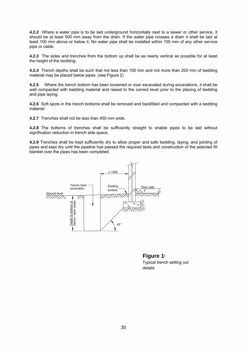
30
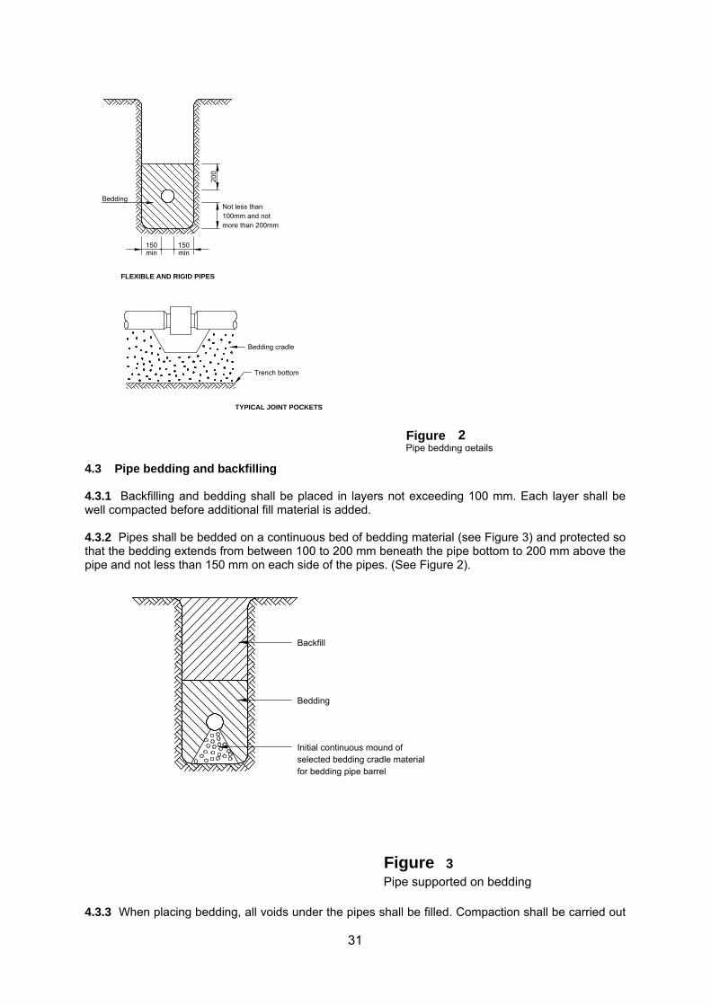
4.2.2 Where a water pipe is to be laid underground horizontally next to a sewer or other service, it should be at least 500 mm away from the drain. If the water pipe crosses a drain it shall be laid at least 100 mm above or below it. No water pipe shall be installed within 100 mm of any other service pipe or cable. 4.2.3 The sides and trenches from the bottom up shall be as nearly vertical as possible for at least the height of the bedding. 4.2.4 Trench depths shall be such that not less than 100 mm and not more than 200 mm of bedding material may be placed below pipes. (see Figure 2) 4.2.5 Where the trench bottom has been loosened or over excavated during excavations, it shall be well compacted with bedding material and raised to the correct level prior to the placing of bedding and pipe laying. 4.2.6 Soft spots in the trench bottoms shall be removed and backfilled and compacted with a bedding material. 4.2.7 Trenches shall not be less than 450 mm wide. 4.2.8 The bottoms of trenches shall be sufficiently straight to enable pipes to be laid without signification reduction in trench side space. 4.2.9 Trenches shall be kept sufficiently dry to allow proper and safe bedding, laying, and jointing of pipes and kept dry until the pipeline has passed the required tests and construction of the selected fill blanket over the pipes has been completed.
Floor slab
Typical trench setting out
Figure 104
details
45°
Existingsurface
Dep
th to
bot
tom
of
tren
ch /
tank
var
ies
Trench /tankexcavation
Ground level
> 1500
31
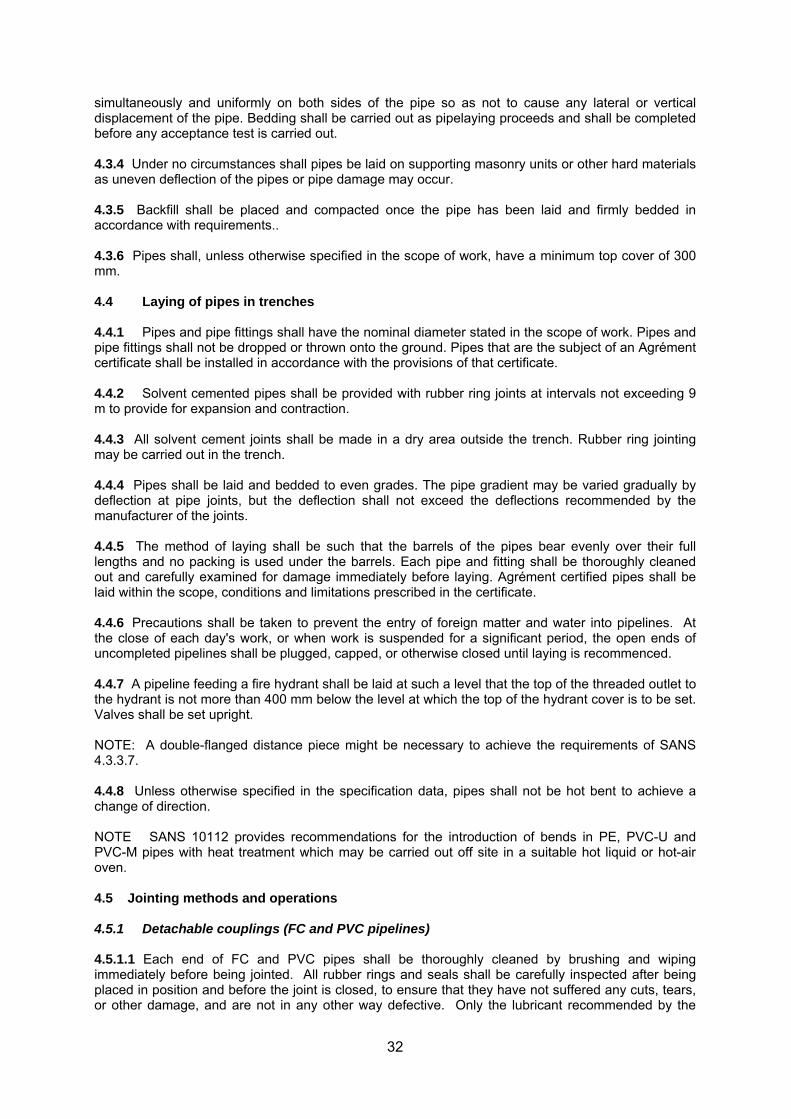
4.3 Pipe bedding and backfilling 4.3.1 Backfilling and bedding shall be placed in layers not exceeding 100 mm. Each layer shall be well compacted before additional fill material is added. 4.3.2 Pipes shall be bedded on a continuous bed of bedding material (see Figure 3) and protected so that the bedding extends from between 100 to 200 mm beneath the pipe bottom to 200 mm above the pipe and not less than 150 mm on each side of the pipes. (See Figure 2).
4.3.3 When placing bedding, all voids under the pipes shall be filled. Compaction shall be carried out
TYPICAL JOINT POCKETS
Trench bottom
Bedding cradle
FLEXIBLE AND RIGID PIPES
Not less than100mm and notmore than 200mm
150min
Bedding
RIGID PIPES (OPTIONAL)
20
0
150min
Pipe bedding detailsFigure 105
150min
150min
Bedding
Pipe supported on bedding
Figure 106
Backfill
Bedding
Initial continuous mound of selected bedding cradle material for bedding pipe barrel
2
3
32
simultaneously and uniformly on both sides of the pipe so as not to cause any lateral or vertical displacement of the pipe. Bedding shall be carried out as pipelaying proceeds and shall be completed before any acceptance test is carried out. 4.3.4 Under no circumstances shall pipes be laid on supporting masonry units or other hard materials as uneven deflection of the pipes or pipe damage may occur. 4.3.5 Backfill shall be placed and compacted once the pipe has been laid and firmly bedded in accordance with requirements.. 4.3.6 Pipes shall, unless otherwise specified in the scope of work, have a minimum top cover of 300 mm. 4.4 Laying of pipes in trenches 4.4.1 Pipes and pipe fittings shall have the nominal diameter stated in the scope of work. Pipes and pipe fittings shall not be dropped or thrown onto the ground. Pipes that are the subject of an Agrément certificate shall be installed in accordance with the provisions of that certificate. 4.4.2 Solvent cemented pipes shall be provided with rubber ring joints at intervals not exceeding 9 m to provide for expansion and contraction. 4.4.3 All solvent cement joints shall be made in a dry area outside the trench. Rubber ring jointing may be carried out in the trench. 4.4.4 Pipes shall be laid and bedded to even grades. The pipe gradient may be varied gradually by deflection at pipe joints, but the deflection shall not exceed the deflections recommended by the manufacturer of the joints. 4.4.5 The method of laying shall be such that the barrels of the pipes bear evenly over their full lengths and no packing is used under the barrels. Each pipe and fitting shall be thoroughly cleaned out and carefully examined for damage immediately before laying. Agrément certified pipes shall be laid within the scope, conditions and limitations prescribed in the certificate. 4.4.6 Precautions shall be taken to prevent the entry of foreign matter and water into pipelines. At the close of each day's work, or when work is suspended for a significant period, the open ends of uncompleted pipelines shall be plugged, capped, or otherwise closed until laying is recommenced. 4.4.7 A pipeline feeding a fire hydrant shall be laid at such a level that the top of the threaded outlet to the hydrant is not more than 400 mm below the level at which the top of the hydrant cover is to be set. Valves shall be set upright. NOTE: A double-flanged distance piece might be necessary to achieve the requirements of SANS 4.3.3.7. 4.4.8 Unless otherwise specified in the specification data, pipes shall not be hot bent to achieve a change of direction. NOTE SANS 10112 provides recommendations for the introduction of bends in PE, PVC-U and PVC-M pipes with heat treatment which may be carried out off site in a suitable hot liquid or hot-air oven. 4.5 Jointing methods and operations 4.5.1 Detachable couplings (FC and PVC pipelines) 4.5.1.1 Each end of FC and PVC pipes shall be thoroughly cleaned by brushing and wiping immediately before being jointed. All rubber rings and seals shall be carefully inspected after being placed in position and before the joint is closed, to ensure that they have not suffered any cuts, tears, or other damage, and are not in any other way defective. Only the lubricant recommended by the
33
manufacturer shall be used for sleeve-type couplings and rubber insertion rings of FC pipes. Polyurethane joints for PVC pipes shall be lubricated with soft soap or similar material approved by the manufacturer. Grease derived from petroleum products shall not be used in PVC pipe joints. 4.5.1.2 PVC pipelines shall be jointed in accordance with the manufacturer's instructions. 4.5.1.3 FC pipelines shall be jointed in accordance with the manufacturer's instructions. Joints in such pipelines with ductile iron detachable couplings shall have gaps, after laying and jointing, of approximately 10 mm between the ends of the pipes and central to the collar, to allow for expansion when the pipes are filled and have absorbed moisture. 4.5.2 Flanges (steel pipelines) 4.5.2.1 In the jointing of steel pipes with flanges, care shall be taken to align, grade, and level the pipes, specials, and valves to avoid straining of the flanges. All bitumen and paint shall be removed from the mating face of each flange immediately before jointing. Insertion pieces that have accurately cut holes for bolts shall be placed to form a continuous one-piece ring between the flanges. Bolts shall be tightened up evenly in opposite pairs to ensure uniform bearing on the insertion. Care shall be taken to avoid damage to the internal surfaces of the pipes during assembly of the pipeline. 4.5.2.2 Wherever loose flanges are welded onto pipelines, the pipe linings shall be restored to the thickness specified and the new linings shall be soundly jointed to the existing linings. 4.5.3 Jointing of PE, PP, PVC-U and PVC-M pipes 4.5.3.1 Welding of thermoplastics 4.5.3.1.1 The welding of polypropylene homopolymer, polypropylene block copolymer, polypropylene random copolymer, polyvinylidene fluoride and high-density polyethylene using the heated-tool butt welding and heated-tool socket welding processes shall be undertaken in accordance with the requirements of SANS 10268-1 using equipment that satisfies the requirements of SANS 1671-1. 4.5.3.1.2 The welding of polyethylene and polypropylene pipes by means of electrofusion shall be in accordance with the requirements of SANS 10268-2. The acceptability of the weld shall be assessed in accordance with the assessment table contained in SANS 10268-10. 4.5.3.1.3 The joining of unplasticized polyvinyl chloride (PVC-U) and chlorinated polyvinyl chloride (PVC-C) using the solvent welding process shall be in accordance with the requirements of SANS 10268-5. 4.5.3.1.4 Welders shall, where specified in the specification data, be tested and certified in accordance with the requirements of SANS 10269 and be in possession of a valid test certificate. 4.5.3.2 Thermofusion of polypropylene pipes 4.5.3.2.1 Butt-fusion welding and electrofusion of polypropylene pipes shall be carried out by suitable trained and skilled operators using equipment that satisfies the requirements of SANS 1671-1 or SANS 1671-2. Electrofusion control units and butt fusion welding machines shall be used strictly in accordance with the supplier’s instructions and the provisions of SANS 10268-1. 4.5.3.2.2 Before use, metal heating plates shall be cleaned of all traces of polyethylene remaining from previous operations to avoid inclusion of oxidized polyethylene in the weld. 4.5.3.2.3 The pipe ends of all pipes jointed by means of an electrofusion fitting shall be prepared prior to jointing by scraping off any surface oxide and being thoroughly cleaned with a suitable cleaner. 4.5.3.2.4 The two elements that are to be jointed in the butt-welding process shall be not be under tension or lateral stress during the welding operation.
34
4.5.3.2.5 Welders shall, where specified in the specification data, be tested and certified in accordance with the requirements of SANS 10269 and be in possession of a valid test certificate. NOTE: Unskilled application of the thermofusion process is likely to produce joints which appear satisfactory on inspection but which may contain stresses and brittle areas which might result in the eventual failure of the joint. 4.5.3.3 Hot welding of PVC-U piping 4.5.3.3.1 Hot welding shall be carried out by suitable trained and skilled operators in accordance with the requirements of SANS 10112 using equipment that satisfies the requirements of SANS 1671-3. 4.5.3.3.2 Welders shall, where specified in the specification data, be tested and certified in accordance with the requirements of SANS 10269 and be in possession of a valid test certificate. 4.5.3.4 Compression fittings The end of the pipe shall be inserted into the fitting past the rubber sealing ring. The nut that compresses the sealing ring shall then be hand tightened and thereafter turned with a suitable spanner a further 1¼ turns to compress the grip ring onto the pipe. Care shall be taken to: a) not over-tighten the elastic ring which is in contact with the PVC pipe as the tightness of the joint
may be impaired under pressure b) ensure that if the other end of piece of pipe is already jointed to another pipe, such pipe does not
turn during the screwing process and stress the existing fittings. NOTE: Sealing is obtained with a light compression of the elastomeric sealing ring due to the smooth surface of the pipe. 4.5.3.5 Screwed joints on polyethylene pipes 4.5.3.5.1 Screw threads may, unless otherwise stated in the specification data, be cut on PE 63, PE40 and PE 32 pipes polyethylene pipes, provided that a clean sharp suitable die is used. 4.5.3.5.2 The die shall be washed in petrol and wiped clean and dry to ensure that no oil is applied to the pipe during the cutting of the thread. 4.5.3.5.3 The end of the pipe shall be cut off square before the die is run on, and a mandrel shall be inserted in the end of the pipe to support it against the die. The thread shall be cut in one pass without end-pressure on the die. The length threaded shall be such that all the threads will enter the joint, so that no threads will be left exposed. 4.5.3.5.4 Metal sockets or injection-moulded plastics sockets (or elbows, tees, crosses reducers, etc.) may be used to complete the joint after wrapping the thread with PTFE tape and hand tightening. Care shall be taken in screwing up the joint to not over-stress the screw thread by applying excessive torque to the socket or to the pipe. Only strap wrenches which grip the pipe with a strap fabric shall be used to finally tighten the joint if necessary. NOTE 1 A set of dies should be kept specifically for use with polyethylene pipes. Special dies for threading polyethylene pipes are available and should be used in preference to the dies normally used on metal pipes. NOTE 2 The use of ordinary jointing compound and hemp in the joint might damage the joint. 4.5.3.6 Rubber ring type integral pipe and sockets 4.5.3.6.1 The groove which houses any rubber ring where such ring is supplied separately shall be thoroughly cleaned prior to the location of the rubber ring in such groove.
35
4.5.3.6.2 The spigot end shall be square to the axis of the pipeline and suitably chamfered. Both the spigot and the rubber ring shall be lubricated with a suitable lubricant recommended by the pipe manufacturer prior to insertion into the socket. As soon as the spigot and sealing ring have been lubricated, the pipe shall be introduced into the socket, after it has been correctly aligned, so as to prevent any risk of contamination by sand or particles of grit. 4.5.3.6.3 The spigot shall be inserted into the socket up to the reference (depth-of-entry) mark made by the manufacturer or a mark measured by the installer to ensure the correct penetration of the pipe into the sealing element of the joint and guarantees sealing under pressure. 4.6 Concrete casing, anchor and thrust blocks 4.6.1 Where required in terms of the scope of work pipes shall be encased in grade 15 concrete, unless otherwise indicated. No part of the concrete casing shall be closer than 150 mm to any flexible joint of a concrete-encased pipeline. No earthfilling over the concrete shall be commenced until at least 2 days after the concrete has been placed. 4.6.2 Anchor and thrust blocks shall, unless otherwise specified in the scope of work, be constructed to dimensions shown on Figure 4 at tees, bends, terminal valves, end caps where the joint between the pipe and such fittings is not of the self anchoring type or is not a welded connection. 4.6.3 Anchor or thrust blocks and pedestals shall be constructed of grade 15 concrete unless otherwise stated in the scope of work. 4.6.4 The concrete shall be well punned round the pipe and, if in trenches, against the undisturbed faces and bottom of the trench. Backfilling may not be placed behind or under thrust faces. Excess excavation shall be replaced with the concrete as used for anchor or thrust blocks. Care shall be taken to leave the joints accessible. 4.7 Valve and hydrant chambers Valve and hydrant chambers shall unless otherwise specified in the scope of work, be constructed in accordance with the relevant requirements of SANS 2001-DP2. 4.8 Laying from main to erf 4.8.1 Access to properties in built-up areas 4.8.1.1 Where specified in the specification data, a printed notice shall be delivered to the owner or occupier, as appropriate, of each house or building, before operations are commenced, informing him that any existing water supply may be interrupted at short notice. When an erf connection is to be disconnected or shut off, reasonable warning shall be given to the consumer. 4.8.1.2 Where any part of an erf connection is to be installed within the boundaries of an erf, the work shall be arranged in such a way as to cause the least inconvenience to the consumer and the least possible damage to private property. After backfilling, those portions of lawns, flower beds, driveways, and pathways (gravel, tar, paving, or concrete), etc., that have been disturbed shall be made good. 4.8.2 Service connections 4.8.2.1 General 4.8.2.1.1 Holes for ferrules shall be drilled, not punched. On pipes in which ferrules are intended to be fitted while the pipes are under pressure, a suitable special drilling and tapping machine shall be used. 4.8.2.1.2 Any connection showing leakage when tested under the test pressure specified for the water supply main shall be regarded as defective and the pipe length with the defective connection shall be replaced and retested.
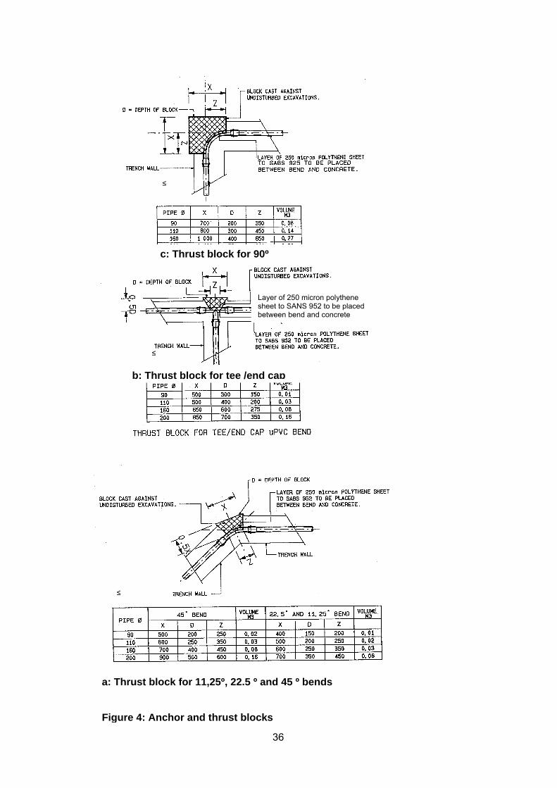
36
c: Thrust block for 90º
b: Thrust block for tee /end cap
a: Thrust block for 11,25º, 22.5 º and 45 º bends Figure 4: Anchor and thrust blocks
≤
≤
≤
Layer of 250 micron polythene sheet to SANS 952 to be placed between bend and concrete
37
4.8.2.2 FC pipes 4.8.2.2.1 Except where plug-in type (expanding) ferrules are specified in the scope of work, and except where the water main is of Class 18 (CID) or Class C (COD) or better and has a wall thick enough for direct tapping, saddles shall be used for service connections to FC pipes. The nominal diameter of ferrules used for direct tappings in FC pipes shall not exceed 20 mm for pipes of nominal diameter 100 mm and 150 mm, and shall not exceed 25 mm for pipes of nominal diameter greater than 150 mm. 4.8.2.2.2 A service connection to an AC pipeline may be made a) at a joint by using
1) a long collar detachable joint, or 2) a CI detachable coupling that is longer than the standard sleeve and incorporates a
platform with a tapped hole to which a service connection can be attached, or b) on a pipe section at a position not less than 300 mm from the end of the pipe by one of the
following methods:
1) The pipe shall be drilled at the take-off point to a diameter greater than that of the threaded portion of the ferrule. A suitable saddle complete with rubber washer having a hole that has been clearly punched to the size of the ferrule beforehand, shall then be accurately centred over the hole, and bolted round the pipe, the boss being drilled and tapped to the size required for the ferrule. A ferrule of the appropriate size shall then be installed.
2) A saddle complete with rubber washer shall be bolted round the pipe at the take-off point. The hole for the connection shall then be drilled and tapped through the saddle, washer, and pipe and a ferrule of the appropriate size installed.
3) Where plug-in type ferrules for AC pipes are to be used, the pipe shall be drilled to the correct size, and a ferrule of the type and dimensions appropriate to the wall thickness of the pipe shall be installed in accordance with the ferrule manufacturer's instructions.
4.8.2.2.3 In each method given in (b)(1), (2), and (3) in 4.7.2.2.2 the ferrule shall be so installed that, when the connection is tested, there is no sign of visible leakage. 4.8.2.2.3 Ductile iron pipes On ductile iron pipes a service connection shall be made by drilling and tapping the pipe at the take-off point and then fitting a ferrule of the required size in the manner specified in 4.7.2.2.2 b(2). 4.8.2.2.4 Steel pipes Where a service connection is required to be taken off a steel pipe, suitable precautions shall be taken to ensure that any pipe lining or coating is not damaged. 4.8.2.2.5 GRP, PE, PP and PVC pipes On GRP, PE, PP and PVC, the service connections shall be made using suitable saddles in strict accordance with the method recommended by the pipe manufacturer. Pipes shall be cut in such a way that each cut end is smooth and clean. 4.8.2.2.6 Pipes of different materials Pipes and fittings of different materials shall be jointed only with special adaptors recommended by the pipe manufacturer(s). 4.8.2.2.7 Recording of locations
b: Thrust block for tee /end cap
≤
≤
38
Where required in terms of the specification data, the following data shall be recorded in respect of each connection: a) The name of the street; b) The number of the plot or erf; c) The location measurements of the stop tap in relation to the nearest erf peg(s); d) The position of the connection on the supply main relative to lateral erf boundaries; e) The size of the connection. 4.9 Installation of water meters, stop taps and surface boxes 4.9.1 Meters Each meter shall be installed in the position shown on the drawings and in such a manner that the meter can be removed easily after unscrewing the couplings and slightly springing the pipes apart. PTFE sealing tape shall be used to joint threaded couplings. The inlet and outlet of each meter shall be kept securely covered until the meter is installed. Before being installed, each meter shall be blown through carefully in the direction of the arrow on the meter to ensure that it works freely. The meter shall then be set in position with the arrow pointing in the correct direction. 4.9.2 Stop taps Each stop tap shall be installed with the arrow on the body of the tap pointing in the direction of flow. 4.9.3 Installation of surface boxes Each surface box shall be set according to the ground slope, clear of, and in such a way as to afford adequate protection for the meter and stop tap. The inside of the box shall be backfilled to the underside of the meter. 4.9.4 Commissioning of meters When turning on the water at each erf connection, all air shall be expelled from the meter by opening the highest tap on the premises and then slowly opening the stop tap. 4.9.5 Recording of meter installations Where required in terms of the specification data, the following data shall be recorded in respect of each connection: a) The meter type and number. b) The number of the plot or erf. c) The date of installation. d) Any other data specified in the specification data 4.10 Freestanding and wall mounted taps Freestanding and wall mounted external taps shall be supported in such a manner that they are capable of supporting a 50 kg weight hung the spout of the tap. . 5 Compliance with requirements 5.1 Tolerances No deviation will be permitted from the minimum cover above the pipe specified or shown on the drawings.
39
5.2 Materials testing Materials for pipelines shall be tested in accordance with the relevant requirements of the standards applicable to such materials. 5.3 Hydraulic pipeline test 5.3.1 Water installations which incorporate fire hydrants shall be hydraulically tested in accordance with the requirements of SANS 2001-DP2 at a field test pressure of 1500kPa. 5.3.2 Water installations which do not incorporate fire hydrants shall, unless otherwise specified in the specification data, be tested at the working pressure in the supply mains. All visible leaks shall be made good and any pipe, special, or fitting found to be defective shall be removed and replaced and such replacement material shall, after installation, be tested.