Embed Size (px)
Citation preview

Holographically encoded volumephase masks
Marc SeGallIvan DivlianskyClémence JollivetAxel SchülzgenLeonid B. Glebov
Downloaded From: http://opticalengineering.spiedigitallibrary.org/ on 07/30/2015 Terms of Use: http://spiedigitallibrary.org/ss/TermsOfUse.aspx

Holographically encoded volume phase masks
Marc SeGall, Ivan Divliansky,* Clémence Jollivet, Axel Schülzgen, and Leonid B. GlebovUniversity of Central Florida, College of Optics and Photonics, P.O. Box 162700, Orlando, Florida 32816-2700, United States
Abstract. Wepresent here amethod to create spectrally addressable phasemasks by encoding phase profiles intovolume Bragg gratings, allowing these holographic elements to be used as phasemasks at any wavelength capableof satisfying the Bragg condition of the hologram. Moreover, this approach enables the capability to encode andmultiplex several phase masks into a single holographic element without cross-talk while maintaining a high dif-fraction efficiency. As examples, we demonstrate fiber mode conversion with near-theoretical conversion efficiencyas well as simultaneous mode conversion and beam combining at wavelengths far from the original hologramrecording wavelength. © The Authors. Published by SPIE under a Creative Commons Attribution 3.0 Unported License. Distribution or reproductionof this work in whole or in part requires full attribution of the original publication, including its DOI. [DOI: 10.1117/1.OE.54.7.076104]
Keywords: holographic optical elements; phase masks; volume gratings; Bragg gratings; laser beam shaping; laser beam combining.
Paper 150252P received Feb. 27, 2015; accepted for publication Jun. 15, 2015; published online Jul. 13, 2015.
1 IntroductionOver the last decades, phase masks have found numerousapplications, including imaging,1–5 encryption,6–9 beamshaping,10–14 and mode conversion.15–18 To create permanentphase masks there are two typical methods of production.The first method controls the local geometrical path lengthby generating a contoured surface,5,10–15 while the secondmethod changes the local refractive index in the bulk of aphotosensitive medium such as lithium niobate or photosen-sitive glass.19,20 Both methods can be employed to generatephase masks with almost any profile. However, because thephase shift is induced by changing the local optical pathlength, these phase masks are inherently limited to use ata specific wavelength, which limits the range of potentialapplications. To increase this range, achromatic phase maskshave been previously produced utilizing either birefringentmaterials or the birefringence in diffraction gratings withperiods below the working wavelength.21,22 Other techniquesinclude wavelength multiplexing several computer-gener-ated holograms so that arbitrary wavefronts can be generatedwhen illuminated by the appropriate wavelength beam.23–25
This technique will allow the diffracted beam to havethe same wavefront for multiple incident wavelengths, butrequires that a separate hologram be recorded for each desiredwavelength. Therefore, to make this a truly achromatic device,many holograms must be recorded and the diffraction effi-ciency of each hologram will necessarily be reduced.
We demonstrate here that such a complex method forachromatization is unnecessary for certain phase profiles.Instead, a quasiachromatic element can be generated byencoding stepped phase mask profiles into transmitting vol-ume Bragg gratings (TBGs),26,27 which produce holographicphase masks (HPMs). Though this technique has been dem-onstrated for HPMs utilized at reconstruction wavelengthsidentical to the recording wavelength,28,29 we show herethat HPMs can produce identical diffracted phase profilesover a wide range of wavelengths as long as the Bragg con-dition of the volume grating is satisfied. This is in contrast to
more complex holograms that, though they can be read atany wavelength satisfying the Bragg condition, cannot gen-erally reconstruct the same phase profile at wavelengths dif-ferent than the recording one. To simplify fabrication and toprovide a clear demonstration of the phenomenon, we choseto use binary phase profiles, but the approach is fully appli-cable for multilevel phase masks as well. The HPM utilizesthe diffraction characteristics of TBGs, which can diffractup to 100% of a beam into a single order and can diffractover a broad range of wavelengths by changing the angle ofincidence (with the diffraction efficiency depending on thewavelength and strength of the grating).26 The high-angularselectivity of a TBG also allows for several TBGs to bemultiplexed into the same element with little to no cross-talkbetween gratings; each grating is accessed by altering thebeam’s angle of incidence onto the element.
In order to explain the unique properties of the HPMs, wenote that a Bragg grating is the simplest volume hologram,which, unlike more complex holograms, can, by changingthe incident angle, diffract a different wavelength withoutdistorting the beam profile. By encoding phase levels whichcover a macroscopic area, the HPM acts locally as a standardTBG with a given phase shift. Thus, the HPM will diffract inthe same manner as a standard TBG except at the relativelysmall number of phase discontinuities, and the diffractedbeam’s phase profile will match the encoded phase level pro-file regardless of incident wavelength. The HPM, therefore,acts as a spectrally addressable phase mask, and by applyingsurface gratings with double the period of the HPM, a trulyachromatic element will be created.30
In this paper, we focus exclusively on the properties of theHPM itself, and demonstrate HPMs that, though recorded at325 nm, preserve a binary phase profile in the diffractedbeam at wavelengths beyond 1 μm and can operate over abandwidth larger than 500 nm. These elements are used toperform fiber mode conversion and simultaneous TEMmodeconversion and spectral beam combining.
2 Theory of HPM Encoding and OperationTo encode the phase profile into a TBG, consider the holo-graphic recording setup in Fig. 1. Here, a multilevel phase*Address all correspondence to: Ivan Divliansky, E-mail: [email protected]
Optical Engineering 076104-1 July 2015 • Vol. 54(7)
Optical Engineering 54(7), 076104 (July 2015)
Downloaded From: http://opticalengineering.spiedigitallibrary.org/ on 07/30/2015 Terms of Use: http://spiedigitallibrary.org/ss/TermsOfUse.aspx

mask has been placed into one arm of a two-beam interfer-ence system (the object beam), where the two beams inter-fere at an angle θ relative to the normal of the holographicsample. The two-beam interference equation describing thefringe pattern in the sample is then
I ¼ I1 þ I2 þ 2ffiffiffiffiffiffiffiffiI1I2
pcos½ðk
⇀
1 − k⇀
2Þ · r⇀ þ ϕðx; y; zÞ�; (1)
where I is the intensity, k⇀
i is the wavevector for each beam,and ϕ is the phase variation introduced by the phase maskafter the object beam has propagated to the sample. Since thephase mask’s profile is located in the x0–y plane, which isrotated with respect to the sample plane, the recorded phaseprofile will generally be different than the phase mask.However, if the thickness of the sample, the axial distancebetween the phase mask and the sample, and θ are smallthen ϕðx; y; zÞ ≈ ϕðx; yÞ ≈ ϕðx0; yÞ, so the phase profilerecorded in the hologram will be approximately the same asthat of the original phase mask. The recorded hologram willhave a refractive index profile of
nðx; y; zÞ ¼ n0 þ n1 cos½K⇀ · r⇀ þ ϕðx; yÞ�; (2)
where n0 is the background refractive index, n1 is the refrac-
tive index modulation, and K⇀ ¼ k
⇀
1 − k⇀
2 is the gratingvector.
Once the hologram is recorded, it is placed in a systemwith some probe beam to be diffracted which may or may nothave the same wavelength as the recording beams. If theprobe beam is incident at or near the Bragg condition (seeKogelnik26), the total electric field will satisfy the scalarHelmholtz wave equation,
∇2E − k2pn2E ¼ 0: (3)
Here, kp is the wavenumber of the probe beam. For thickvolume gratings, where only a single incident and diffractedbeam contain significant energy, the Helmholtz equation hasa solution of the form26
Eðx; y; zÞ ¼ Aðx; y; zÞeð−ik⇀
p·r⇀Þ þ Bðx; y; zÞeð−ik
⇀
d·r⇀Þ; (4)
where A and B are the complex amplitudes of the transmitted
and diffracted waves, respectively, and k⇀
d ¼ k⇀
p − K⇀
is thewavevector of the diffracted beam. Insertion of Eq. (4) intoEq. (3) results in a set of coupled wave equations between theamplitudes A and B. Kogelnik26 has solved these equationswhen A and B depend solely on the axial distance z (homog-enous gratings). However, when a phase mask is placed inthe recording system, the phase term is not a constant acrossthe entire hologram aperture and consequently it cannotbe assumed that this one-dimensional dependence will stillhold. In this particular study, we are only interested in probebeams that exactly satisfy the Bragg condition. In this case,the coupled wave equations become
1
kp
�kp;x
∂A∂x
þ kp;y∂A∂y
þ kp;z∂A∂z
�¼ −iκe−iϕðx;yÞB
1
kp
�kd;x
∂B∂x
þ kd;y∂B∂y
þ kd;z∂B∂z
�¼ −iκeiϕðx;yÞA:
(5)
Here, κ ¼ πn1∕λ0 is the coupling coefficient of the grating.Note that we have assumed that the second derivatives arenegligibly small in the same manner as Kogelnik,26 as westill expect the transfer of energy between the transmittedand diffracted waves to be slow.
We solve the coupled equations numerically by con-verting Eq. (4) into Fourier space along the transverse dimen-sions x and y, giving
2πikp
ðfxkp;x þ fykp;yÞAþ kp;zkp
∂A∂z
¼ Ff−iκe−iϕðx;yÞBg
2πikp
ðfxkd;x þ fykd;yÞBþ kd;zkp
∂B∂z
¼ Ff−iκeiϕðx;yÞAg;(6)
where A and B are the Fourier transforms of A and B, respec-tively, and fx and fy are the spatial frequencies along thex and y axes, respectively. To solve these equations, we splitthe propagation and energy transfer between the waves intotwo discrete steps and successively propagate and transferenergy between waves over several small propagation steps.To calculate the propagation of the beam, the right side ofEq. (6) is assumed to be zero. In this case, the Fourier ampli-tudes will have a solution of the form
Aðfx; fy; zþ ΔzÞ ¼ Aðfx; fy; zÞe�−i 2π
kp;zðfxkp;xþfykp;yÞΔz
�
Bðfx; fy; zþ ΔzÞ ¼ Bðfx; fy; zÞe�−i 2π
kd;zðfxkd;xþfykd;yÞΔz
�:
(7)
Note that this is only exact in the case where the right side ofEq. (6) truly equals zero, but for small (∼100 nm) propaga-tion steps, this is a reasonable approximation. To accountfor energy transfer, we piecewise integrate the right side ofEq. (5) with the Euler method and add it to the inverseFourier transform of Eq. (7)
Aðx;y;zþΔzÞ¼F−1fAðfx;fy;zþΔzÞg−iκe−iϕðx;yÞBðx;y;zÞΔzBðx;y;zþΔzÞ¼F−1fBðfx;fy;zþΔzÞg−iκeiϕðx;yÞAðx;y;zÞΔz:
(8)
Calculations indicate that for a propagation step size of100 nm, our numerical method conserves energy to within0.01% after propagating the coupled waves through theentire system, which is sufficient for the phase profiles dis-cussed here.
Numerical simulations were performed to determine thediffracted beam phase profile and diffraction efficiency of anHPM in the case where a binary phase profile is encoded.The numerical method described previously was first appliedto simulate a standard TBG with an 8-μm period, a refractiveindex modulation of 250 ppm, and a thickness of 2 mm. Theprobe beam with a wavelength of 1064 nm is incident at theBragg angle and propagates in the x–z plane [see Fig. 2(a)].Using a propagation step size of 100 nm, the simulated dif-fraction efficiency of this TBG is 99.13%, which is consis-tent with the peak diffraction efficiency of a homogenousTBG described by Kogelnik.26 A π phase step was then intro-duced to the grating at a recording wavelength of 325 nm.This binary step was first introduced along the x-axis, andthen along the y-axis, to determine if there would be anyorientation-dependent variations in diffraction efficiency or
Optical Engineering 076104-2 July 2015 • Vol. 54(7)
SeGall et al.: Holographically encoded volume phase masks
Downloaded From: http://opticalengineering.spiedigitallibrary.org/ on 07/30/2015 Terms of Use: http://spiedigitallibrary.org/ss/TermsOfUse.aspx

phase profile. The calculations were then repeated for twoprobe beams with wavelengths of 632 and 975 nm. In allcases, the grating parameters are the same but the incidentangle was changed so that all beams were incident at theirrespective Bragg angles.
As shown in Fig. 2(b), each diffracted beam contains aπ phase shift when the phase step is introduced along thex-axis. The location of the phase step is slightly offset
from the origin due to the propagation of the beam throughthe sample, and changes for each beam due to their differentBragg angles. For the local intensities of the diffractedwaves, shown in Fig. 2(c) for a plane wave, (note that therelative strengths are different due to the wavelength-depen-dent diffraction efficiency) a general decrease in diffractedenergy is observed at the phase discontinuity. This is not sur-prising, as any region of the probe beam crossing the phasediscontinuity will not be able to satisfy the Bragg conditionat that point. This inability to locally satisfy the Braggcondition will result in a decrease in diffraction efficiency(which is the total energy in the diffracted beam dividedby the total energy in the incident beam) that is dependenton the fraction of the beam energy which crosses the phasediscontinuity. This decrease in diffraction efficiency will alsomask the slight differences in phase for each wavelength inthe phase transition region. However, as shown in Fig. 2(d),this loss in efficiency becomes very small with increasingbeam size and the diffraction efficiency of an HPM willasymptotically approach the diffraction efficiency of a stan-dard TBG as the beam diameter approaches infinity.
When the phase discontinuity is oriented along the y-axis,the phase profile of the diffracted beam will also have a πphase shift, as shown in Fig. 2(e). Here, the phase disconti-nuity is located at the origin because the probe beam has nocomponent propagating along the y-axis. This zero y-axiscomponent results in the diffracted beam having a nearzero-width transition region that is identical for every
Fig. 1 The phase profile of a standard binary phase mask in theobject beam is encoded into a volume Bragg grating at a recordingwavelength of 325 nm.
Fig. 2 (a) A probe beam incident at the Bragg angle is diffracted by a holographic phase mask (HPM)with a single phase dislocation along one axis. Numerical simulations results demonstrating: (b) the dif-fracted beam phase profile and (c) the local diffracted intensity of a plane wave for beams of differentwavelength. (d) The diffraction efficiency of an HPM at 1064 nm relative to a standard transmitting volumeBragg grating as a function of beam diameter when a binary phase dislocation is encoded along thex -axis. Here, the coordinate origin is the center of the front surface of the HPM. (e) The diffracted beamphase profile and (f) the local diffracted intensity when a binary phase dislocation is encoded along they -axis for beams of different wavelength.
Optical Engineering 076104-3 July 2015 • Vol. 54(7)
SeGall et al.: Holographically encoded volume phase masks
Downloaded From: http://opticalengineering.spiedigitallibrary.org/ on 07/30/2015 Terms of Use: http://spiedigitallibrary.org/ss/TermsOfUse.aspx

wavelength. It also results in only a single infinitesimal frac-tion of the beam ever encountering the phase discontinuity,giving constant local intensities for the diffracted waves, asshown in Fig. 2(f). The simulated diffraction efficiency of theHPM in this case is constantly within 0.01% of the predictedefficiency for a TBG at each wavelength as given byKogelnik26 regardless of beam diameter, and given thatthere is a 0.01% uncertainty in energy conservation in thenumerical method, we conclude that the diffraction effi-ciency is identical to a standard TBG. These two cases indi-cate that the diffracted beam from an HPM will alwaysinherit the phase profile of the original phase mask, andwill have some orientation-specific decrease in diffractionefficiency that is dependent on beam size and largely negli-gible for most typical beam diameters. Repeating these casesfor other wavelengths at their respective Bragg angles showsimilar results, with the diffraction efficiency of both theTBG and HPM changing with respect to wavelength asdescribed by Kogelnik.26 Thus, the HPM will maintainthe diffraction characteristics of a TBG, including the wave-length and angular spectrum, while preserving the desiredphase profile over the whole bandwidth of possible Braggwavelengths.
3 Experiments
3.1 HPMs
A complete set of experiments have been performed using anHPM recorded in a 1.97-mm thick photo-thermo-refractive(PTR) glass sample as illustrated in Fig. 1. PTR glass is amulticomponent photosensitive glass with a transparencywindow from the near UV to the near IR which has the abil-ity to sustain high power beams.31–33 It has been used ina variety of applications, including producing volume phasemasks20 and holograms for pulse stretching/compression34 aswell as coherent and spectral beam combining.35–37 To fab-ricate the HPM, a four-sector binary phase mask20 designedfor the recording wavelength of 325 nm was placed in onearm of the setup and the half angle of interference was set to0.786 deg, giving a grating period of 8 μm. The phase maskwas placed approximately 150 mm from the sample.
In order to directly and accurately compare the diffractionefficiency of the HPM with that of a standard TBG, we fab-ricated a sample containing both an HPM and a homo-geneous TBG in the same volume of PTR glass. This wasdone by recording an HPM, and then removing the phasemask from the object beam and rotating the PTR glass sam-ple without lateral shifting to record a tilted TBG with thesame recording dosage. Recording both elements in the samevolume ensured that the local refractive index change andany sample inhomogeneities would be shared between theelements and demonstrated a new opportunity for holo-graphic phase mask multiplexing. As shown in Fig. 3, thediffraction efficiencies of each element are approximately thesame, showing good agreement with theoretical predictions.Note also that there is no cross-talk between the two multi-plexed holograms, demonstrating that the HPM preserves thenarrow angular acceptance of standard TBGs.
3.2 Mode Conversion
As demonstrated previously,20 a four-sector binary phasemask can itself be used as an optical mode converter
when the probe beam center is properly aligned with respectto the phase steps. Such a binary phase mask though worksonly for the particular wavelength for which the phase shift isπ. As shown in Fig. 4(a), the expected far-field intensity pro-file for a beam passing through the center of a four-sectorregular binary phase mask consists of a four-lobed cloverpattern. However, since the phase shift is only π at the designwavelength, this is the only wavelength with effective mode,as has been demonstrated by recent results for fiber modes.38
To demonstrate the capabilities of HPMs, we encoded such afour sector phase mask in a transmission volume Bragg gra-ting, thus creating a mode converting HPM. Here, we reporta series of experiments to test the theoretical predictions ofthe HPM multiwavelength operation presented above. If theencoded binary phase steps are indeed transferred to theprobe beams diffracted from the HPM at their respectiveBragg wavelengths, the HPM should simultaneously act asa diffraction element and a mode converter, when the beamsare correctly aligned to the phase steps. To perform thisinvestigation, we recorded the far-field intensity distributionsof diffracted beams at multiple wavelengths by imaging themonto a CCD camera using a 500-mm lens.
Three beams (3-mm in diameter at 1∕e2) at wavelengthsin the visible and the infrared regions were applied to studythe wavelength dependence of diffraction and mode conver-sion using the HPM. As shown in Figs. 4(b)–4(d), for thethree very different Bragg wavelengths (632.8, 975, and1064 nm), the diffracted beam profiles exhibited the pre-dicted four-lobed pattern. This clearly confirms our initialthesis that the binary phase profile is being preserved inthe diffracted order for an extremely broad range of wave-lengths. To further verify the binary phase step in the dif-fracted beam, an interferometric experiment was developedand is presented in Fig. 5(a).
A 1064-nm laser was collimated and split into two armsof a Mach–Zehnder interferometer. The HPM was placed inone arm and rotated so that the beam incident on the HPMwas at the Bragg angle, and the two beams were recombinedand imaged onto a camera. In this experiment, the beam inci-dent on the HPM was horizontally offset from the center sothat the HPM acted as a two-sector binary mask. As shown inFigs. 5(b) and 5(c), the interference fringes of the upper andlower lobes produced by the HPM have a relative π phaseshift, confirming that the encoded phase profile is preservedin the diffracted beam at wavelengths far from the recordingwavelength.
Fig. 3 Diffraction efficiency angular spectrum of an HPM and homog-enous grating.
Optical Engineering 076104-4 July 2015 • Vol. 54(7)
SeGall et al.: Holographically encoded volume phase masks
Downloaded From: http://opticalengineering.spiedigitallibrary.org/ on 07/30/2015 Terms of Use: http://spiedigitallibrary.org/ss/TermsOfUse.aspx
3.3 Fiber Mode Conversion
In this section, we consider another practical application forHPM elements by studying the conversion of fiber modes.This is of particular interest for applications such as powerscaling of fiber lasers and amplifier systems, as higher-ordermodes (HOMs) propagating in fibers can carry more energythan the fundamental mode since their mode area is signifi-cantly larger. As a result, several fiber lasers and amplifiersystems have been recently demonstrated with improved per-formances by using HOMs39–41 which, at some point, have toreconvert to the desired mode.
In this context, we investigated the ability of the HPM toconvert higher-order fiber modes into the fundamental mode;the usually preferred output beam of high-power fiber lasersand amplifiers. A diagram of the experiment is shown inFig. 6, where a 1064-nm laser beam is coupled into a single-mode fiber to produce a high-quality fundamental modeGaussian beam. The Gaussian beam is then collimated anddirected onto a reflecting spatial light modulator (SLM).Applying the SLM encoding technique by Arrizón etal.,42 the incident beam was converted into the LP11 and LP21HOMs. These modes were selected because their spatialphase pattern match the HPM with the encoded four-sectorbinary phase profile previously presented. The generatedHOMs were then directed onto the HPM and the far-fieldof the diffracted order was analyzed.
Because the LP modes form an orthonormal basis, we candefine the conversion efficiency of a converted beam withrespect to a desired mode by the overlap integral
Fig. 4 (a) Simulated far-field profile of a beam after passing throughan ideal four-sector binary mask and the diffracted beam from a four-sector HPM at (b) 632.8 nm, (c) 975 nm, and (d) 1064 nm. The sizesshown here are not to scale.
Fig. 5 (a) Mach–Zehnder interferometer measuring the relative phase between the upper and lowerlobes of the diffracted beam from the HPM. (b) The resulting interferogram with markers indicatingtwo line cuts, and (c) the line cuts of the two lobes compared to each other, showing a relative πphase difference. Note that the line cuts do not appear to be completely out of phase due to the slighttilt of the fringes, which can be seen in (b).
Optical Engineering 076104-5 July 2015 • Vol. 54(7)
SeGall et al.: Holographically encoded volume phase masks
Downloaded From: http://opticalengineering.spiedigitallibrary.org/ on 07/30/2015 Terms of Use: http://spiedigitallibrary.org/ss/TermsOfUse.aspx

η ¼ j RR E�convElpdaj2RR jEconvj2da
RR jElpj2da: (9)
Here, Econv is the electric field of the converted beam, Elpis the desired LP mode, (*) represents the complex conjuga-tion, and a is the area. This integral will equal zero if theHPM does not alter the original mode and will equalunity for a complete conversion, and as such it may be con-sidered as equivalent to the mode purity of the converted
beam with respect to a given mode. Note that because theencoded phase profiles considered here are binary, they can-not convert a pure LP mode to another pure LP mode with100% efficiency. Using Eq. (9), we find that the theoreticalconversion efficiency from the fundamental mode to theLP11 mode (whether odd or even) using a binary phasemask is 71.8%, while the theoretical maximum conversionefficiency to the LP21 mode is 64.4%. The conversion effi-ciency from a pure HOM to the fundamental mode is iden-tical to the conversion efficiency from the fundamental modeto the HOM.
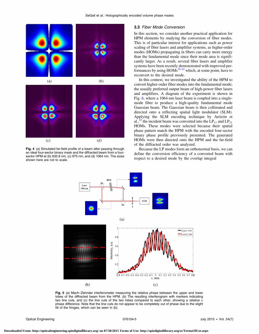
As shown in Fig. 7, by selecting different positions of thebeam (indicated by the red spots) relative to the four-sectorsof the HPM, various fiber modes can be generated. To cal-culate the experimental conversion efficiencies, we utilizedan extension of Eq. (9), which is described in Ref. 20; theexperimentally achieved conversion efficiencies are listed inTable 1. The fundamental mode LP01 has been converted tothe even and odd LP11 modes as well as the LP21 mode withefficiencies up to 70%, indicating that the calculatedmaximum conversion efficiencies can be reached in theexperiments. Slight deviations may be attributed to inhomo-geneities in the sample and the finite extent of the transitionregion between areas with different phases. The reverse con-version efficiency from the LP21 mode to the fundamentalmode is in excellent agreement with the calculated theoreti-cal maximum, indicating that HPMs have the same conver-sion efficiencies as standard binary phase masks.
Note that, in addition to efficient mode conversion, sizematching between the free space beam waist of the convertedbeam and the fiber mode also has to be considered forthe overall mode converter efficiency. This issue has beenaddressed in detail for conventional narrow band phase platemode converters.38 Similar overall efficiency results areexpected for broadband HPM-based fiber mode converters,but are beyond the scope of this paper.
3.4 Simultaneous Mode Conversion and BeamCombining
Beam combining offers the potential to scale the powerof laser systems beyond the limits of individual lasers.
Fig. 6 A 1064-nm beam passes through a single-mode fiber and thenis diffracted from a spatial light modulator to generate various LPmodes, which are then converted by a holographic phase mask modeconverter and examined in the far-field.
Table 1 Conversion efficiency of a binary holographic phase maskwhen converting between LP modes.
Conversion efficiency (%)
Mode converted Calculated [Eq. (9)] Experimental (�1.0)
LP01 to LP11;e 71.8 69.5
LP01 to LP11;o 71.8 64.0
LP01 to LP21 64.4 69.8
LP21 to LP01 64.4 65.2
Fig. 7 Far-field profiles of converted modes: (a) LP01 mode converted to higher order modes and (b) theLP21 mode converted to the LP01 mode.
Optical Engineering 076104-6 July 2015 • Vol. 54(7)
SeGall et al.: Holographically encoded volume phase masks
Downloaded From: http://opticalengineering.spiedigitallibrary.org/ on 07/30/2015 Terms of Use: http://spiedigitallibrary.org/ss/TermsOfUse.aspx
Currently, spectral beam combining and coherent beam com-bining are the two dominant methods in the effort to reachmultikilowatt diffraction-limited beams. In parallel, as dis-cussed above, fibers that support HOMs are considered toovercome the power limitations of fiber lasers and amplifiers.Therefore, the combination of several HOM beams fromdifferent lasers into one high-power fundamental modebeam suggests itself as a power scaling approach. Here, wedescribe a method to accomplish this task by taking advan-tage of the mode-converting capabilities of HPMs.
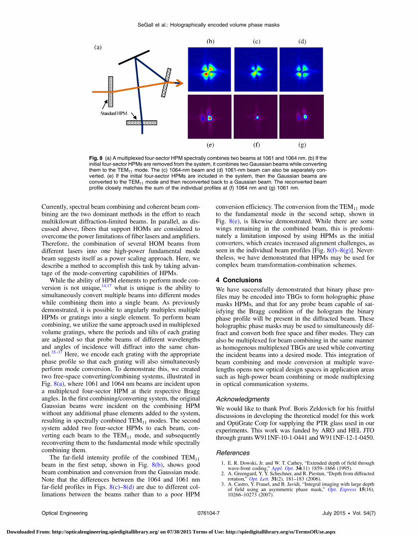
While the ability of HPM elements to perform mode con-version is not unique,14,17 what is unique is the ability tosimultaneously convert multiple beams into different modeswhile combining them into a single beam. As previouslydemonstrated, it is possible to angularly multiplex multipleHPMs or gratings into a single element. To perform beamcombining, we utilize the same approach used in multiplexedvolume gratings, where the periods and tilts of each gratingare adjusted so that probe beams of different wavelengthsand angles of incidence will diffract into the same chan-nel.35–37 Here, we encode each grating with the appropriatephase profile so that each grating will also simultaneouslyperform mode conversion. To demonstrate this, we createdtwo free-space converting/combining systems, illustrated inFig. 8(a), where 1061 and 1064 nm beams are incident upona multiplexed four-sector HPM at their respective Braggangles. In the first combining/converting system, the originalGaussian beams were incident on the combining HPMwithout any additional phase elements added to the system,resulting in spectrally combined TEM11 modes. The secondsystem added two four-sector HPMs to each beam, con-verting each beam to the TEM11 mode, and subsequentlyreconverting them to the fundamental mode while spectrallycombining them.
The far-field intensity profile of the combined TEM11
beam in the first setup, shown in Fig. 8(b), shows goodbeam combination and conversion from the Gaussian mode.Note that the differences between the 1064 and 1061 nmfar-field profiles in Figs. 8(c)–8(d) are due to different col-limations between the beams rather than to a poor HPM
conversion efficiency. The conversion from the TEM11 modeto the fundamental mode in the second setup, shown inFig. 8(e), is likewise demonstrated. While there are somewings remaining in the combined beam, this is predomi-nately a limitation imposed by using HPMs as the initialconverters, which creates increased alignment challenges, asseen in the individual beam profiles [Fig. 8(f)–8(g)]. Never-theless, we have demonstrated that HPMs may be used forcomplex beam transformation-combination schemes.
4 ConclusionsWe have successfully demonstrated that binary phase pro-files may be encoded into TBGs to form holographic phasemasks HPMs, and that for any probe beam capable of sat-isfying the Bragg condition of the hologram the binaryphase profile will be present in the diffracted beam. Theseholographic phase masks may be used to simultaneously dif-fract and convert both free space and fiber modes. They canalso be multiplexed for beam combining in the same manneras homogenous multiplexed TBGs are used while convertingthe incident beams into a desired mode. This integration ofbeam combining and mode conversion at multiple wave-lengths opens new optical design spaces in application areassuch as high-power beam combining or mode multiplexingin optical communication systems.
AcknowledgmentsWe would like to thank Prof. Boris Zeldovich for his fruitfuldiscussions in developing the theoretical model for this workand OptiGrate Corp for supplying the PTR glass used in ourexperiments. This work was funded by ARO and HEL JTOthrough grants W911NF-10-1-0441 andW911NF-12-1-0450.
References
1. E. R. Dowski, Jr. and W. T. Cathey, “Extended depth of field throughwave-front coding,” Appl. Opt. 34(11) 1859–1866 (1995).
2. A. Greengard, Y. Y. Schechner, and R. Piestun, “Depth from diffractedrotation,” Opt. Lett. 31(2), 181–183 (2006).
3. A. Castro, Y. Frauel, and B. Javidi, “Integral imaging with large depthof field using an asymmetric phase mask,” Opt. Express 15(16),10266–10273 (2007).
Fig. 8 (a) A multiplexed four-sector HPM spectrally combines two beams at 1061 and 1064 nm. (b) If theinitial four-sector HPMs are removed from the system, it combines two Gaussian beams while convertingthem to the TEM11 mode. The (c) 1064-nm beam and (d) 1061-nm beam can also be separately con-verted. (e) If the initial four-sector HPMs are included in the system, then the Gaussian beams areconverted to the TEM11 mode and then reconverted back to a Gaussian beam. The reconverted beamprofile closely matches the sum of the individual profiles at (f) 1064 nm and (g) 1061 nm.
Optical Engineering 076104-7 July 2015 • Vol. 54(7)
SeGall et al.: Holographically encoded volume phase masks
Downloaded From: http://opticalengineering.spiedigitallibrary.org/ on 07/30/2015 Terms of Use: http://spiedigitallibrary.org/ss/TermsOfUse.aspx

4. N. Caron and Y. Sheng, “Polynomial phase masks for extending thedepth of field of a microscope,” Appl. Opt. 47(22), E39–E43 (2008).
5. H. Zhao et al., “Cubic sinusoidal phase mask: another choice to extendthe depth of field of incoherent imaging system,” Opt. Laser Technol.42, 561–569 (2010).
6. B. Javidi and J. Horner, “Optical pattern recognition for validation andsecurity verification,” Opt. Eng. 33(6), 1752–1756 (1994).
7. L. Neto and Y. Sheng, “Optical implementation of image encryptionusing random phase encoding,” Opt. Eng. 35(9), 2459–2463 (1996).
8. C. Cheng et al., “Optical joint transform encryption using binary phasedifference key mask,” Opt. Rev. 12(5), 367–371 (2005).
9. P. Kumar, J. Joseph, and K. Singh, “Impulse attack-free four randomphase mask encryption based on a 4-f optical system,” Appl. Opt.48(12), 2356–2363 (2009).
10. J. R. Leger, D. Chen, and Z. Wang, “Diffractive optical element formode shaping of a Nd:YAG laser,” Opt. Lett. 19(2), 108–110 (1994).
11. J. Yang and M. Wang, “Analysis and optimization on single-zonebinary flat-top beam shaper,” Opt. Eng. 42(11), 3106–3113 (2003).
12. X. Huang, M. Wang, and C. Yu, “High-efficiency flat-top beam shaperfabricated by a nonlithographic technique,” Opt. Eng. 38(2), 208–213(1999).
13. M. Wang, C. Yu, and A. Varela, “Efficient pseudo-nondiffracting beamshaping using a quasicontinuous-phase diffractive element,” Opt. Eng.40(4), 517–524 (2001).
14. K. O. Hill et al., “Bragg gratings fabricated in monomode photosen-sitive optical fiber by UVexposure through a phase mask,” Appl. Phys.Lett. 62, 1035–1037 (1993).
15. W. Mohammed et al., “Selective excitation of the LP11 mode in stepindex fiber using a phase mask,” Opt. Eng. 45(7), 074602 (2006).
16. A. Shyouji et al., “Diffraction-grating-type phase converters for con-version of Hermite-Laguerre-Gaussian mode into Gaussian mode,”Appl. Opt. 49(9), 1513–1517 (2010).
17. M. Beresna et al., “Radially polarized optical vortex converter createdby femtosecond laser nanostructuring of glass,” Appl. Phys. Lett. 98,201101 (2011).
18. C. Rotschild et al., “Adjustable spiral phase plate,” Appl. Opt. 43(12),2397–2399 (2004).
19. K. Peithmann et al., “Low-spatial-frequency refractive-index changesin iron-doped lithium niobate crystals upon illumination with a focusedcontinuous-wave laser beam,” J. Opt. Soc. Am. B 17(4), 586–592(2000).
20. M. SeGall et al., “Binary volume phase masks in photo-thermo-refrac-tive glass,” Opt. Lett. 37(7), 1190–1192 (2012).
21. M. Bass, Handbook of Optics, 2nd ed., McGraw-Hill, New York, NY(1994).
22. D. Mawet et al., “Achromatic four quadrant phase mask coronagraphusing the dispersion of form birefringence,” in Astronomy withHigh Contrast Imaging, C. Aime and R. Soummer, Eds., CambridgeUniversity, Cambridge (2003).
23. J. Rosen, M. Segev, and A. Yariv, “Wavelength-multiplexed computer-generated volume holography,” Opt. Lett. 18(9), 744–746 (1993).
24. G. A. Rakuljic, V. Leyva, and A. Yariv, “Optical data storage by usingorthogonal wavelength-multiplexed volume holograms,” Opt. Lett.17(20), 1471–1473 (1992).
25. T. D. Gerke and R. Piestun, “Aperiodic volume optics,” Nat. Photonics4, 188–193 (2010).
26. H. Kogelnik, “Coupled wave theory for thick volume holograms,” BellSystem Tech. J. 45(9), 2909–2944 (1969).
27. I. Ciapurin, L. Glebov, and V. Smirnov, “Spectral combining of high-power fiber laser beams using Bragg grating in PTR glass,” Proc. SPIE5335, 116–124 (2004).
28. K. Aoki et al., “Selective multimode excitation using volume holo-graphic mode multiplexer,” Opt. Lett. 38(5), 769–771 (2013).
29. Y. Wakayama et al., “Mode demultiplexer using angularly multiplexedvolume holograms,” Opt. Express 21(10), 12920–12933 (2013).
30. S. Wu et al., “Broadband angular filtering with a volume Bragg gratingand a surface grating pair,” Opt. Lett. 39(14), 4068–4071 (2014).
31. J. Lumeau et al., “Origin of crystallization-induced refractive indexchanges in photo-thermo-refractive glass,” Opt. Mater. 32, 139–146(2009).
32. L. B. Glebov, “Photochromic and photo-thermo-refractive glasses,” inEncyclopedia of Smart Materials, M. Schwartz, Ed., Vol. 2, JohnWiley & Sons, Hoboken, New Jersey (2002).
33. I. Divliansky et al., “High-power semiconductor lasers for applicationsrequiring GHz linewidth source,” Proc. SPIE 7198, 71981N (2009).
34. G. Chang et al., “Femtosecond Yb-fiber chirped-pulse-amplificationsystem based on chirped-volume Bragg gratings,” Opt. Lett. 34(19),2952–2954, (2009).
35. D. Ott et al., “Scaling the spectral beam combining channels in a multi-plexed volume Bragg grating,” Opt. Express 21(24), 29620 (2013).
36. C. Lu et al., “Coherent beam combination of fiber laser arrays viamultiplexed volume Bragg gratings,” in Conf. on Lasers and Electro-Optics: Science and Innovations, OSA Technical Digest Series(Optical Society of America, 2012), paper CF2N.2 (2012).
37. A. Jain et al., “Efficient coherent beam combining of fiber lasers usingmultiplexed volume Bragg gratings,” in Conf. on Lasers and Electro-Optics: Science and Innovations, OSA Technical Digest Series(Optical Society of America, 2012), paper CF2N.8 (2012).
38. K. Igarashi et al., “Performance evaluation of selective mode conver-sion based on phase plates for a 10-mode fiber,” Opt. Express 22(17),20881–20893 (2014).
39. J. W. Nicholson et al., “A higher-order-mode Erbium-doped-fiberamplifier,” Opt. Express 18(17), 17651–17657 (2010).
40. J. W. Nicholson et al., “Scaling the effective area of higher-order-modeerbium-doped-fiber amplifiers,” Opt. Express 20(22), 24575–24584(2012).
41. X. Peng et al., “High-order mode fiber enables high energy chirped-pulse amplification,” Opt. Express 21(26), 32411–32416 (2013).
42. V. Arrizón et al., “Pixelated phase computer holograms for the accurateencoding of scalar complex fields,” J. Opt. Soc. Am. A 24(11), 3500–3507 (2007).
Marc SeGall received his PhD in optics from the University of CentralFlorida in Orlando, Florida, USA, in 2013. He is currently a researchscientist at Physical Optics Corporation. Prior to joining PhysicalOptics, he was a graduate student at the University of CentralFlorida where he researched the effects of volume phase masks.His current research interests include head worn displays, non-mechanical beam steering systems, and holography.
Ivan Divliansky received his PhD in electrical engineering/materialsscience from The Pennsylvania State University in State College,Pennsylvania, USA in 2004. Since 2007, he has been a seniorresearch scientist at CREOL, the College of Optics and Photonicsat the University of Central Florida in Orlando. His current researchinterests include high-power laser beam combining, diode and fiberlasers systems design, implementation of volume Bragg gratings indifferent photonics areas, vector beams generation, and others.
Clémence Jollivet received her PhD in optics from the University ofCentral Florida in 2014. Highlights of her work are compiled in the PhDdissertation entitled “Specialty fiber lasers and novel fiber devices.”Currently, her research interests include design and fabrication ofspecialty optical fibers, specialty fiber lasers, novel fiber devices,and advanced characterization techniques such as modal analysis.Since 2014, she has been working as a scientist in the Fiber R&DDepartment of Nufern Inc.
Axel Schülzgen received his PhD in physics from Humboldt-University of Berlin, Germany, in 1992. Since 2009, he has been aprofessor of optics at CREOL, the College of Optics and Photonics,University of Central Florida in Orlando. Prior to joining CREOL, hewas a faculty member at the College of Optical Sciences, Universityof Arizona in Tucson. His current research interests include opticalfiber devices and components with applications in fiber laser systemsand fiber optic sensing.
Leonid B. Glebov: Biography is not available.
Optical Engineering 076104-8 July 2015 • Vol. 54(7)
SeGall et al.: Holographically encoded volume phase masks
Downloaded From: http://opticalengineering.spiedigitallibrary.org/ on 07/30/2015 Terms of Use: http://spiedigitallibrary.org/ss/TermsOfUse.aspx