Embed Size (px)
Citation preview

52 · History and Applications of Diamond-Like Carbon Manufacturing Processes
FEATURED TOPIC
1. Introduction
Diamond-like carbon (DLC) first appeared in a paper in 1971. DLC was discovered by accident during research on vapor-phase synthesis of diamond. In the 1950s, high-pressure synthesis of crystalline diamond was developed but it required special and expensive equipment. Therefore, a lot of research was conducted on vapor-phase synthesis for growing diamond crystals from hydrocarbon gas or carbon vapor (gaseous phase).(1) During this process, Aisenberg et al. published a paper on an amorphous hard film mainly composed of carbon in 1971, which was later called DLC.(2) After that, various DLC deposition processes and films were developed. Having superior characteristics as a lubrica-tive material, such as a low coefficient of friction, high hardness, and chemical stability, DLC films have driven forward development in a unique way different from the vapor-phase synthesis of crystalline diamond. In partic-ular, the low friction coefficient of DLC has been drawing attention due to the requirement to address environmental problems, and the importance of DLC has been increasing in reducing the fuel consumption of automobile engines by decreasing friction, being intro-duced as driving components and pump components to prevent seizure. Starting from the history of processes for producing DLC films, this paper intro-duces the classification techniques and features of the DLC films we have developed and their applications in this order.
2. DLC Deposition Processes and Their Features
The methods for producing DLC films are broadly divided into two types: Physical Vapor Deposition (PVD) and Chemical Vapor Deposition (CVD). The PVD method uses a solid (graphite) as the carbon source and the CVD method uses a gas (a hydrocarbon such as methane). The PVD method is further divided into the arc, sputter, and laser vapor deposition methods.
The CVD method includes radio-frequency (RF), direct-current (DC) discharge, Penning ionization gauge (PIG), and self-discharge methods. Figure 1 is a conceptual diagram showing the RF discharge plasma CVD, PIG plasma CVD, and arc PVD adopted by us.
2-1 Radio-frequency discharge plasma CVD methodThe methods for producing DLC by exposing a
base material to glow discharge plasma of a hydro-carbon gas were actively studied in the latter half of the 1970s, and many papers were published until the first half of the 1980s.(3) The major methods for generating glow discharge in decompressed gas include the DC discharge and RF discharge methods. Many of them apply the high-frequency power or a negative DC voltage to the base material, which is the cathode, and the counter anode is kept at the ground potential. Acetylene (C2H2) or methane (CH4) is used as the raw material gas. A DLC film containing hydrogen is obtained by emitting an active species such as ions and
History and Applications of Diamond-Like Carbon Manufacturing Processes
Hideki MORIGUCHI*, Hisanori OHARA and Masanori TSUJIOKA
----------------------------------------------------------------------------------------------------------------------------------------------------------------------------------------------------------------------------------------------------------Diamond-like carbon (DLC) is a hard material with lubricity and chemical stability. Amid the growing awareness of environmental problems in late years, DLC films have been used to reduce the fuel consumption of automobiles by reducing friction loss. The films are also used as a coating of cutting tools for aluminum alloys that have been widely used for automobile weight reduction. Nippon ITF Inc. provides DLC films most suitable for the customer needs by utilizing its equipment, systems, and expertise. This paper introduces the history of DLC manufacturing processes and DLC films that we have commercialized.
----------------------------------------------------------------------------------------------------------------------------------------------------------------------------------------------------------------------------------------------------------Keywords: DLC, PVD, CVD, coating, low friction
CVD (Radio-Frequency Discharge Method)
CVD(PIG Method)
PVD (Arc Discharge Method)
Substrate
Insulator
ExhaustMatchingBox
13.56MHz
Ar,H2
CxHy
DC-pulse
FilamentAnode
Magnetic Coil
PIG-plasmasource
Ar,H2,CxHy Graphite TargetArc Vapor Source
Exhaust
SubstrateSubstrate
Insulator Insulator
Exhaust
Fig. 1. Typical DLC Production Process

SEI TECHNICAL REVIEW · NUMBER 82 · APRIL 2016 · 53
radicals*1 in hydrocarbon gas plasma onto the surface of the base material kept at a relatively low tempera-ture.2-2 PIG plasma CVD method
This process also forms a DLC film by exposing hydrocarbon gas to plasma. However, since it can control the amount of carbon ions incident upon the base material and the energy of the incident carbon ions independently, it is classified as the remote plasma CVD method, which produces a DLC film containing hydrogen. This method allows the easy control of the thickness, hardness, residual stress, and composition of a DLC film. These features of the CVD method make the DLC film coating applicable to various shapes of a base material, allowing for a wide range of applications. In addition, plasma occurs in a wide range of conditions, and the input power and raw material gas can be used relatively efficiently. Although inferior in film hardness compared to the arc PVD method mentioned below, this method can form films with a wider range of char-acteristics than the RF method and can even produce DLC with a film thickness of 60 µm. Since the PIG method has flexibility in controlling the hardness and thickness of the film, it can form a film on soft metal base material such as aluminum.2-3 Sputtering/Plasma CVD-composite method
The sputter vapor deposition method forms a carbon film on a base material by applying a DC voltage or high-frequency power to a sputter vapor source made of solid graphite, and making positive ions in inert gas plasma collide against graphite to pump out carbon atoms.(4) It can form a smooth DLC film, but has a disadvantage of a low film deposition rate due to a low carbon sputter yield. A DLC film can be formed in the same manner as the plasma CVD method by letting hydrocarbon gas flow into a furnace. The film deposi-tion rate is significantly increased compared to the sputter vapor deposition method that does not use hydrocarbon gas. If metal is used as the sputter vapor source, a DLC film containing a metallic element can be produced. Sputtering with a simple graphite material is classified as a pure PVD method, and forms a DLC film without hydrogen. If a hydrocarbon gas is used, it is classified as a remote plasma CVD method, generating a DLC film with hydrogen.2-4 Arc PVD method
The cathode arc PVD method forms a DLC film on the surface of a base material at a negative potential by generating a continuous vacuum arc discharge on the surface of a solid graphite cathode to efficiently generate carbon ions. This method was developed in the former Soviet Union, and creation of a DLC film that does not contain hydrogen was reported as early as in the 1970s.(5) Then, when this technology was introduced to Western nations in the late 1970s, the development was accelerated in Australia and Europe, and then in the United States. This process features easy formation of hard hydrogen-free DLC films that contain more diamond (sp3-bonded carbon) and less graphite (sp2-bonded carbon) because of the high vaporization and ionization rates of graphite. In addition, with a rela-
tively small size vapor source, it is possible to form a film at a high speed on large base material by operating many vapor sources at the same time.
It has the disadvantage of film contamination with coarse particles, called droplets or macro particles, which are left unionized during arc discharge, resulting in an increase in surface roughness, increasing aggres-siveness.2-5 Filtered arc PVD method
As a means to prevent the coarse particles mentioned before from reaching the base material, a magnetic filter cathode arc vapor source that combines a geometrically bent duct and a magnetic field was developed in the former Soviet Union in the 1970s, and the deposition of a hard carbon film with a low number of defects was reported.(6) However, the magnetic filter reduces the utilization efficiency of the vapor source, which decreases the film deposition rate and processing area, resulting in a reduction in productivity. In addition, some coarse particles reflect inside the duct reaching the base material, and the equipment cost is high.
Table 1 shows the structure and characteristics of a DLC film formed by each process.
3. DLC Classification Method
For DLC classification, Casiraghi et al. organized DLC types on a pseudo ternary phase diagram and clarified the relationship with deposition methods.(7) DLC films formed with the sputter vapor deposition method and arc PVD method do not contain hydrogen as long as only solid graphite is used as the raw material and no hydrocarbon gas is used. They are characterized by the differences in the amount of sp3-bonded carbon and the structure of the cluster within the range from graphite-like carbon (GLC) that does not contain hydrogen and amorphous carbon (a-C) to tetrahedral amorphous carbon (ta-C) in Fig. 2. On the other hand, DLC films produced from a hydrocarbon gas using the plasma CVD method always contain hydrogen. These DLC films take the form of hydrogenated amorphous
Table 1. Structures and Characteristics of DLC Production Processes
ProcessDLC
structureCharacteristics
Radio-Frequency Method
a-C:H (Hydrogen containing DLC)
Smooth and low friction (DRY)Able to form films against an insulating substrateSlightly low adhesiveness
PIG Method
a-C:H (Hydrogen containing DLC)
Able to form thick filmsControllable film thickness and stressSlightly inferior film thickness distribution
Self Discharge Method
a-C:H (Hydrogen containing DLC)
Superior coverageAble to form internal coatingHigh deposition rate and filling densitySlightly low adhesiveness
Arc Methodta-C (Hydrogen Free DLC)
Hardness close to diamongLow friction in oilDifficult to form thick films and sensitive to the surface condition
Sputter Methoda-C, ta-C (Hydrogen free)
Supports conductive DLCLow hardness
Pla
sma
CV
DP
VD

54 · History and Applications of Diamond-Like Carbon Manufacturing Processes
carbon (a-C:H) to hydrogenated tetrahedral amorphous carbon (ta-C:H), which are characterized by the differ-ences in the amounts of hydrogen and sp3-bonded carbon. Thus, DLC is distinguished by the amounts of hydrogen and sp3-bonded carbon, and the cluster struc-ture, which provides information for understanding various behaviors including mechanical (hardness and Young’s modulus), optical (refraction, penetration/absorption), electric (conductance), and chemical (changes during an increase in temperature, oxidation, affinity with various materials) behaviors. For example, it has been reported that DLC containing a relatively high amount of hydrogen indicates an excessively low friction coefficient (0.02 or lower) in a dry nitrogen atmosphere and in an ultra-high vacuum, and that Si-added DLC has a low friction coefficient in a humid air atmosphere.(8) On the other hand, in the presence of lubricant oil widely used for automobile parts and mechanical components, the less the hydrogen content in a DLC film, the more the friction coefficient decreases.(9),(10)
4. DLC Films from Nippon ITF
Table 2 shows the classification and characteristics of typical DLC films from Nippon ITF, and Table 3 lists their characteristics and purposes.
4-1 HA-DLCHA-DLC films are formed with the arc PVD method
and do not contain hydrogen. They are hard thin films classified as ta-C with a hardness second to diamond. They are used for tools for cutting aluminum alloys and molds, and are effective in preventing welding of soft metals and resins, improving processing accuracy, and extending life. These films indicate low friction in oil, and superior abrasion resistance even in oil containing a lubricant such as Mo-DTC. In 2006, they were applied to mass production as low-friction films for valve lifters, which are automobile engine components.
Figure 3 compares the results of cutting an aluminum alloy (ADC12) by a normal cemented carbide tool and a cemented carbide tool coated with HA-DLC. While the non-coated cemented carbide tool indicated an excessive adhesion of aluminum, the tool coated with HA-DLC had little adhesion. Figure 4 indicates the result of evaluating cutting forces. The tools coated with HA-DLC had lower cutting forces compared to a normal cemented carbide tool in both dry and wet conditions. This is because a DLC film is less likely to cause
ta-C:H
ta-C
a-Ca-C:H
GLC
Diamond
Graphite
PLC(Polymar
likecarbon)
sp3 /
(sp3
+sp
2 ) (
%)
100
90
80
70
60
50
40
30
20
10
00 10 20 30 40 50 60 70
Hydrogen (at%)
Fig. 2. Classification of DLC
Table 3. Characteristics and Applications of DLC Films from Nippoin ITF
Grade name
Scratch Strength (N)
High Surface Pressure
Sliding (N)Characteristics Typical Applications
HA ≒ 60 > 5000 High hardnessLow friction in oil
Tools, molds for soft metals such as AlEngine components
HAX ≒ 50 > 5000 High hardnessLow defect density
Precision moldsLens molds
HC ≒ 60 > 5000 High durabilityAble to form thick films Engine components
HT ≒ 50 3000 Low internal stressGeneral machine partsAutomobile parts(except engine)
HP ≒ 50 Not measured
Able to form internal coating Internal coating of Pipe
HS ≒ 80 > 5000 Low aggressiveness Automobile parts(except engine)
F Not measured
Not measured
Low temperature treatmentSupports polymers
Rubber parts(Low friction, Fixing prevention)
HA-DLCNon coated
Rak
e Fa
ceFl
ank
Face
Cutting conditionsSpeed: 300m/min, Feed: 0.15mm/t,Ad = Rd = 5mm, Length:9m, Work: ADC12Tool: WEM3032E, APET160504PDFR-SMachine: Makino Machining Center (V55)
Fig. 3. Adhesion Resistance in Cutting Aluminum
Table 2. Characteristics of DLC Films from Nippon ITF
Grade name
Classifi-cation
Thick-ness (µm)
Surface Roughness
Rz (µm)
Hard-ness
(GPa)
Oxidation Temperature
(°C)
Sub-strate
Young Modulus
(GPa)
HA ta-C ≤ 11.0
After lap 0.3
60-80 500 Steel WC-Co 600
HAX ta-C ≤ 1 ≤ 0.1 60-80 500 Steel WC-Co 600
HC ta-C:H ≤ 31.0
After lap 0.3
40-60 350 Steel WC-Co 500
HT a-C:Ha-C:H:Si 1-2 0.1-0.5 15-25 300 Metal
Ceramic 150
HP a-C:Ha-C:H:Si 1-10 < 0.2 15-25 300 Metal 150
HS a-C:Ha-C:H:Me 0.5-1.5 < 0.1 20-30 300 Metal 200
F a-C:H 0.3-2 < 0.2 < 15 300 Polymer < 150

SEI TECHNICAL REVIEW · NUMBER 82 · APRIL 2016 · 55
aluminum adhesion and has a lower friction resistance, which smoothly discharges cutting chips.(1 1)
Figure 5 compares the friction coefficients of non-coated SCM415 carburizing material, TiN, hydrogen-containing DLC, hydrogen-free DLC (HA-DLC), and SCM415 material coated with diamond with a mating material of SUJ2 without lubrication and in oil. Without lubrication, the non-coated SCM415 and TiN indicated seizure, but the DLC and diamond-coated products did not have seizure. In oil, hydrogen-free DLC indicated low friction close to the diamond-coated product. This is because that HA-DLC is ta-C containing many sp3-bonded carbon atoms similar to diamond, and oil has superior affinity with sp3 components. The low fric-tion in oil was the main reason for the adoption of HA-DLC in valve lifters, which are components of the dynamic valve system of an automobile engine.(9)
4-2 HC-DLCHC-DLC films are formed by the arc PVD method
and contain hydrogen. They are classified from the ta-C:H to a-C:H groups. These films can use not only solid targets but also a hydrocarbon gas as a raw mate-rial during film formation. They are less hard than HA-DLC and have less surface roughness than HA-DLC.
Therefore, they are superior in chipping resistance and conformability, and have low aggressiveness. It is possible to create DLC films with different hydrogen contents, and to some extent, control film hardness by adjusting the input and pressure of hydrocarbon gas. The expected applications of these films include auto-mobile engine components, as well as various machine parts, and molds for soft metals.4-3 HT-DLC
HT-DLC films are formed with the PIG Plasma CVD method and contains hydrogen. They are classified into a-C:H. Since HT-DLC is suitable for any base material, and the structure and characteristics of the film can be controlled for a wide range of purposes, it is applied to automotive frictional parts and various other machine parts. The drive train parts of an automobile use lubri-cants and grease for smooth sliding. If the lubricant or grease deteriorates or is washed away, vibration or an unusual noise occurs, and in the worst case, seizure takes place. It is sometimes necessary to take wear preventive measures against dust entering from outside. In recent years, bioethanol fuels are sometimes used. Foreign materials from this fuel cannot be completely removed with a filter, which can cause wear of pump parts. These parts are made by casting alumite-treated aluminum for reducing weight and facilitating processing. The evaluation of various DLC films indi-cated that only HT-DLC films can be stably formed on insulating and porous alumite, and HT-DLC was adopted to the mass production of the parts of motorcycle fuel pumps.4-4 HP-DLC
With the PIG plasma CVD method, it is difficult to homogeneously coat inside a pipe or a part with a complicated shape. The film-forming pressure of the normal plasma CVD method is about 0.1 to 10 Pa. In this range of pressure, the thickness of the ion sheath where almost no electrons exist is several tens of millimeters or more. For pipes thinner than this, high-density plasma was not generated inside, and DLC films could not be formed. To overcome this drawback, HP-DLC generates high-density plasma inside the hole by hollow discharge*2 to keep gas pressure at several tens of pascals or higher. Figure 6 shows the range of inner
Cutting conditionsSpeed: 300m/minFeed: 0.15mm/tAd = Rd = 5mmWork: ADC12
Dry Wet
Cut
ting
For
ce (
N)
700
600
500
400
300
200
100
0
MainForce
FeedForce
VerticalForce
MainForce
FeedForce
VerticalForce
Non coated
HA-DLC
Fig. 4. Cutting Forces in Cutting Aluminum
TitaniumNitrideSCM Conventional
DLCHADLC
Diamond
Test conditionsMating material: SUJ2Substrate: SCM415Carburized materialLoad: 80N (max1.5GPa)Sliding speed: 1000m/sec
0.3
0.25
0.2
0.15
0.1
0.05
0
Fric
tion
Coe
ffici
ent
Seizure occurred Seizure
occurred
No lublicant Oil (10W30)
Fig. 5. Friction Coefficients of Various Films without Lubricant and in Oil
Minimum Inner Diameter:3mmDepth:2.5mm(Length:5mm)
Supported range
0
20
40
60
80
100
120
140
160
0 10 20 30 40 50Inner Diameter D (mm)
Dep
th Y
(m
m) D
Y
supported by conventional DLC
SupportedNot supported
Fig. 6. Range of Depths and Diameters inside a Pipe that can be Coated with HP-DLC

56 · History and Applications of Diamond-Like Carbon Manufacturing Processes
diameters and hole depth for which films can be formed with HP-DLC. In the case of a pipe with both ends open, it is possible to process to a depth twice as that in the figure. HP-DLC can be applied to bearings, the inner surface of a cylinder, the holes of a mold, and the inner surface of a pipe for liquid or gas.4-5 F-DLC
F-DLC films are formed with the RF plasma CVD method and contain hydrogen. They are classified into a-C:H. F-DLC was developed as a process that can coat polymers in particular. In general, DLC coating is performed after cleaning the surface of the base mate-rial by emitting Ar or other ions on the surface. Polymer materials have the problem of the rise in temperature during ion emission, negatively impacting their quality. F-DLC uses a method to remove stain on the base material at low temperatures by exposing the surface to hydrogen plasma. With normal plasma CVD methods, the temperature of the base material reaches nearly 200°C, impacting the quality of polymers. Therefore, plasma generation must be intermittently stopped to control temperature rise to 60°C to 80°C, which enables the deposition of DLC films with superior adhesion without deteriorating polymers. In addition, since polymer materials are soft and easily deformed, a normal DLC film cannot follow the deformation, and the film breaks. To prevent this, an F-DLC film has intro-duced cracks in the direction of its thickness. Photo 1 is a scanning electron microscope (SEM) photo of the surface of an F-DLC film. With the existence of cracks inside the film, the film does not break even if the base material is significantly deformed. Figure 7 shows the
friction coefficients of the F-DLC films coated on various rubbers. The friction coefficients of the non-coated surfaces greatly differ between the types of rubber. However, if they are coated with F-DLC, they indicate low friction similar to polytetrafluoroethylene (PTFE). This low friction can be obtained even in dry environ-ments, and great effects can be expected in environ-ments where lubricant or grease cannot be used. Since DLC is chemically stable, and less likely to change in quality in different use environments (heat, oil, etc.) compared to rubber, it is expected to have suitability to preventing adhesion, which is an issue with rubbers.
Figure 8 shows the result of a ball-on-disc test on PTFE and PTFE coated with F-DLC. F-DLC coating reduces abrasion wear by approximately 1/9, with a fric-tion coefficient similar to PTFE. F-DLC has advantages over PTFE in wear resistance and superior dimensional accuracy with a thin-film coating. In applications with a low load on sliding surfaces represented by a ring-on-disc test, PTFE coating indicates lower friction. For high-surface pressure (PV at 1,200 MPa·m/min or higher) and high-precision (1 to 10 µm) purposes, DLC should be selected, and for low-surface pressure (PV lower than 1,200 MPa·m/min) and low-precision (film thickness of 1 to 10 µm), PTFE coating is suitable.
4-6 HS-DLCHS-DLC films are formed with the sputtering/
plasma CVD-composite method, and classified into a-C:H. Superior peel resistance and chipping resistance have been achieved by independently controlling the amount of carbon ions incident upon the base material and the energy of the incident carbon ions to form a DLC film with the quality gradually changing along the depth of the film and by introducing an intermediate layer with superior adhesion. An FZG test*3 of a gear coated with HS-DLC indicated no scuffing damage*4 up to the final 14th-stage in an oil environment without lubricant. HS-DLC has superior adhesion and chipping resistance compared to other plasma CVD films.4-7 Latest DLC films
Nippon ITF has standardized HAX-DLC films formed with the filtered arc method. HAX-DLC films
Equivalentto µ=1, Which isgenerallyindicated
Fric
tion
Coe
ffici
ent
(A.U
.)
CR NBR EPT Urethane Silicone VinylChloride
Substrate
F-DLC
PTFE
Photo 1. SEM Photo of F-DLC
Fig. 7. Friction Coefficients of Various Rubbers Coated with F-DLC
Non-coated F-DLC
Wea
r Vol
ume
(mm
3 )
109876543210
Fig. 8. Wear Characteristic of PTFE Coated with F-DLC
SEI TECHNICAL REVIEW · NUMBER 82 · APRIL 2016 · 57
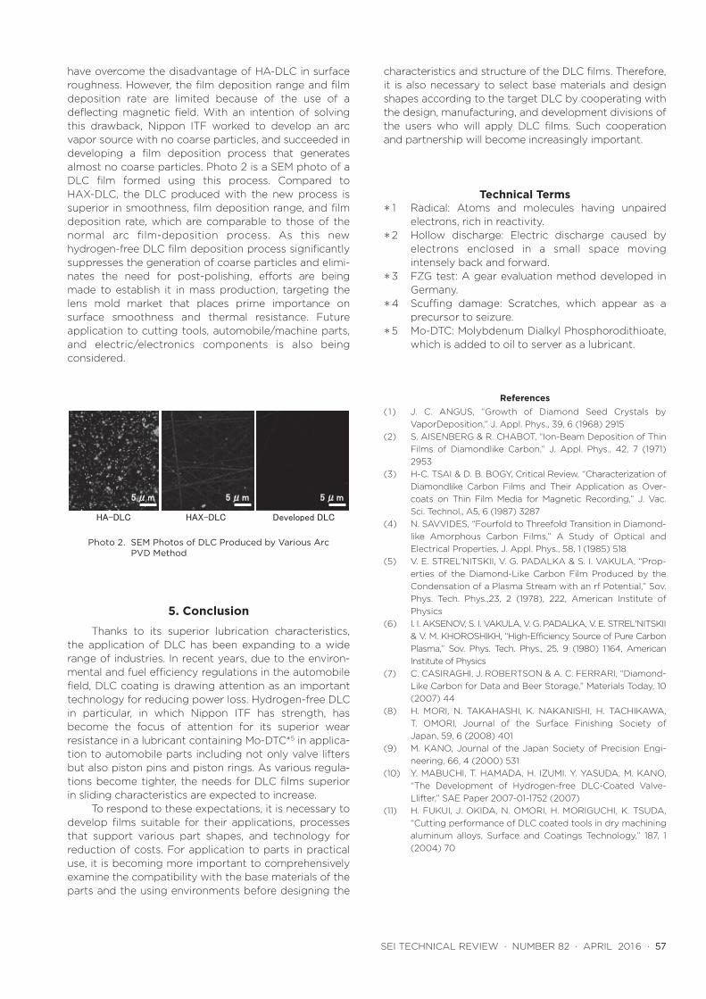
have overcome the disadvantage of HA-DLC in surface roughness. However, the film deposition range and film deposition rate are limited because of the use of a deflecting magnetic field. With an intention of solving this drawback, Nippon ITF worked to develop an arc vapor source with no coarse particles, and succeeded in developing a film deposition process that generates almost no coarse particles. Photo 2 is a SEM photo of a DLC film formed using this process. Compared to HAX-DLC, the DLC produced with the new process is superior in smoothness, film deposition range, and film deposition rate, which are comparable to those of the normal arc film-deposition process. As this new hydrogen-free DLC film deposition process significantly suppresses the generation of coarse particles and elimi-nates the need for post-polishing, efforts are being made to establish it in mass production, targeting the lens mold market that places prime importance on surface smoothness and thermal resistance. Future application to cutting tools, automobile/machine parts, and electric/electronics components is also being considered.
5. Conclusion
Thanks to its superior lubrication characteristics, the application of DLC has been expanding to a wide range of industries. In recent years, due to the environ-mental and fuel efficiency regulations in the automobile field, DLC coating is drawing attention as an important technology for reducing power loss. Hydrogen-free DLC in particular, in which Nippon ITF has strength, has become the focus of attention for its superior wear resistance in a lubricant containing Mo-DTC*5 in applica-tion to automobile parts including not only valve lifters but also piston pins and piston rings. As various regula-tions become tighter, the needs for DLC films superior in sliding characteristics are expected to increase.
To respond to these expectations, it is necessary to develop films suitable for their applications, processes that support various part shapes, and technology for reduction of costs. For application to parts in practical use, it is becoming more important to comprehensively examine the compatibility with the base materials of the parts and the using environments before designing the
characteristics and structure of the DLC films. Therefore, it is also necessary to select base materials and design shapes according to the target DLC by cooperating with the design, manufacturing, and development divisions of the users who will apply DLC films. Such cooperation and partnership will become increasingly important.
Technical Terms* 1 Radical: Atoms and molecules having unpaired
electrons, rich in reactivity.*2 Hollow discharge: Electric discharge caused by
electrons enclosed in a small space moving intensely back and forward.
*3 FZG test: A gear evaluation method developed in Germany.
*4 Scuffing damage: Scratches, which appear as a precursor to seizure.
*5 Mo-DTC: Molybdenum Dialkyl Phosphorodithioate, which is added to oil to server as a lubricant.
References(1) J. C. ANGUS, “Growth of Diamond Seed Crystals by
VaporDeposition,” J. Appl. Phys., 39, 6 (1968) 2915(2) S. AISENBERG & R. CHABOT, “Ion-Beam Deposition of Thin
Films of Diamondlike Carbon,” J. Appl. Phys., 42, 7 (1971) 2953
(3) H-C. TSAI & D. B. BOGY, Critical Review, “Characterization of Diamondlike Carbon Films and Their Application as Over-coats on Thin Film Media for Magnetic Recording,” J. Vac. Sci. Technol., A5, 6 (1987) 3287
(4) N. SAVVIDES, “Fourfold to Threefold Transition in Diamond-like Amorphous Carbon Films,” A Study of Optical and Electrical Properties, J. Appl. Phys., 58, 1 (1985) 518
(5) V. E. STREL’NITSKII, V. G. PADALKA & S. I. VAKULA, “Prop-erties of the Diamond-Like Carbon Film Produced by the Condensation of a Plasma Stream with an rf Potential,” Sov. Phys. Tech. Phys.,23, 2 (1978), 222, American Institute of Physics
(6) I. I. AKSENOV, S. I. VAKULA, V. G. PADALKA, V. E. STREL'NITSKII & V. M. KHOROSHIKH, “High-Efficiency Source of Pure Carbon Plasma,” Sov. Phys. Tech. Phys., 25, 9 (1980) 1 164, American Institute of Physics
(7) C. CASIRAGHI, J. ROBERTSON & A. C. FERRARI, “Diamond-Like Carbon for Data and Beer Storage,” Materials Today, 10 (2007) 44
(8) H. MORI, N. TAKAHASHI, K. NAKANISHI, H. TACHIKAWA, T. OMORI, Journal of the Surface Finishing Society of Japan, 59, 6 (2008) 401
(9) M. KANO, Journal of the Japan Society of Precision Engi-neering, 66, 4 (2000) 531
(10) Y. MABUCHI, T. HAMADA, H. IZUMI. Y. YASUDA, M. KANO, “The Development of Hydrogen-free DLC-Coated Valve-Llifter,” SAE Paper 2007-01-1752 (2007)
(11) H. FUKUI, J. OKIDA, N. OMORI, H. MORIGUCHI, K. TSUDA, “Cutting performance of DLC coated tools in dry machining aluminum alloys, Surface and Coatings Technology,” 187, 1 (2004) 70
HA-DLC HAX-DLC Developed DLC
5μm 5μm 5μm
Photo 2. SEM Photos of DLC Produced by Various Arc PVD Method

58 · History and Applications of Diamond-Like Carbon Manufacturing Processes
Contributors The lead author is indicated by an asterisk (*).
H. MORIGUCHI*• Doctor of Engineering
Executive officer, General Manager, Technology Development Center, Nippon ITF
H. OHARA• General Manager, Inorganic Materials
Department, Advanced Materials Laboratory
M. TSUJIOKA• Executive director, Nippon ITF