Embed Size (px)
Citation preview

Historic Roof Trusses between 1500 and 1700 in German-speaking Central Europe: Documentation, Analysis and
Development
Philip Caston Although historic roof trusses in Central Europe have been the subject of research for around a century, the sheer quantity of them covering buildings from houses to castles, barns to cathedrals and the general lack of interest in these structures has resulted in only a rough explanation of the development of these technical monuments and leaves many gaps open for investigation. It is still possible today to find outstanding examples of technical carpentry, not just unknown to conservation offices and inventories, but also of unique construction which show the ingenuity and indeed the artistic talents of their creators. The data in the two most influential publications on the roof structures of Central Europe (Ostendorf 1908, Binding 1991) can be analysed to show in diagram form the basic evolution of truss design from the oldest known roofs of around 1100 A.D. to the end of the use of handcrafted wooden trusses in the eighteenth century (fig.1). All of these structures are made of wood with the occasional use of iron as bolts or nails. At certain intervals new practices arise which can be put into two categories: a) those which are the direct consequences of the limitations of the building materials used – mainly timber and b) those which must have some other (as yet unknown) reason for change.
Figure 1. Development of the roof truss in Central Europe (delineated: author 2005)
579

The basic construction principle underlying Germanic carpentry is the use of a structural triangle forming a truss spanning the shortest possible distance. Each triangle is made up of one tie-beam and two rafters, joined at all three corners thus forming a plate. The rafters here are integral to the load bearing of the system, transmitting the weight of the roof covering and windloading directly to the crown of the supporting walls. The period between 1500 and 1700 A.D. is extremely exciting for its rich diversity in the construction of trusses. The following four structures are all extreme examples and show how carpenters used different structural solutions during this time. THE NAVE ROOF OF THE CHURCH OF ST. ANDREAS IN LEOBEN-GOESS, STYRIA, AUSTRIA (1510 A.D.) The nave roof is an interesting example of a large late-medieval roof structure in Central Europe (Caston 1995, pp. 6-87). The constructional solution consists of spanning trusses and frames from side to side and spanning timber-framed walls and wall-frames longitudinally, this being modified slightly for the truncated ends of the whole structure. The timber, all spruce wood, for the roof was felled in the winter of 1509/10 and probably turned into the individual roof members the following summer. The basic structural system divides the roof into a number of bays. Each bay consists of a main truss (A) followed by two frames (C), a secondary truss (B) and two further frames (C) following the rhythm: A – C – C – B – C – C – A (fig.2). The main truss (A) is filled out with a main brace consisting of a diagonal strut parallel to but offset from each principal rafter. These struts support a hanging post located on the central axis and are therefore carried through the area below the tie-beam, thus transmitting the load almost directly to the outer walls. The struts overlap the collar beams, posts and raking struts revealing that they were one of the last members to be assembled. This tells us a great deal about the erection sequence of the roof. The whole supporting structure of spine, hanging posts main bracing, struts, wall-frames and timber framed walls allows the frames (C) to be simply constructed of common rafters and collar beams. Just the corners of the main triangle and at the walls are braced with eaves struts. Between each main truss (A) at the ends of a bay four such simple frames were installed reducing the overall weight and quantity of material used in the structure. Between the middle two frames of the bay, a secondary truss (B) supports some of the functions of the main truss. As in the main truss, a main brace runs up parallel to the rafter but only extends from the wall to the top of the third storey. Wall-frame posts and raking braces are included in the construction as in the main frame. The upper half of the truss is devoid of a hanging post and the struts and bracing required to support it. This mixture of a truss and a frame must have a constructional reason, the most obvious one being to keep the weight of the structure over the 10 metre free span of the nave down to a minimum, but is this the only reason?
580
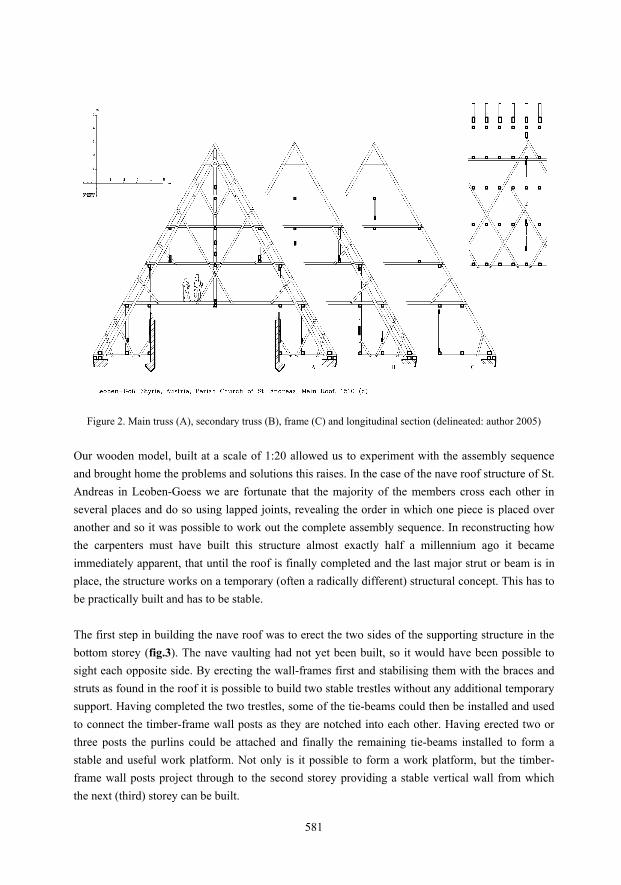
Figure 2. Main truss (A), secondary truss (B), frame (C) and longitudinal section (delineated: author 2005)
Our wooden model, built at a scale of 1:20 allowed us to experiment with the assembly sequence and brought home the problems and solutions this raises. In the case of the nave roof structure of St. Andreas in Leoben-Goess we are fortunate that the majority of the members cross each other in several places and do so using lapped joints, revealing the order in which one piece is placed over another and so it was possible to work out the complete assembly sequence. In reconstructing how the carpenters must have built this structure almost exactly half a millennium ago it became immediately apparent, that until the roof is finally completed and the last major strut or beam is in place, the structure works on a temporary (often a radically different) structural concept. This has to be practically built and has to be stable. The first step in building the nave roof was to erect the two sides of the supporting structure in the bottom storey (fig.3). The nave vaulting had not yet been built, so it would have been possible to sight each opposite side. By erecting the wall-frames first and stabilising them with the braces and struts as found in the roof it is possible to build two stable trestles without any additional temporary support. Having completed the two trestles, some of the tie-beams could then be installed and used to connect the timber-frame wall posts as they are notched into each other. Having erected two or three posts the purlins could be attached and finally the remaining tie-beams installed to form a stable and useful work platform. Not only is it possible to form a work platform, but the timber-frame wall posts project through to the second storey providing a stable vertical wall from which the next (third) storey can be built.
581

Figure 3. Leoben-Goes, St. Andreas, model showing both sides of the lower structure (photo: author 2004)
Figure 4. Leoben-Goes, St. Andreas, model showing cross-bracing of the third storey (photo: author 2004)
582

In building the third storey it would have been necessary to cross-brace the wall frame (fig.4). This could easily have been achieved by using the main braces for the hanging posts, but these would have been impossible to erect without supporting them somehow at the top. Instead the designer chose to incorporate short braces designed specifically to stabilise the structure as build to that point. Thus he constructed a roof structure within a roof structure. The final major step was to erect the spine with its hanging posts. The posts could easily be hung onto the lower purlins in a reversal of their later function and then braced longitudinally. This reconstructed assembly sequence reveals how the designer was concerned in building a structure that was self supporting throughout its different construction phases. He was clever enough to think through the various assembly stages and ended up designing several structures in one single final design. This suggests a man with great practical building experience on site and concerned with safety for those actually involved in building the structure. Around 1510 it was still usual to build using standing trestles, however it was also usual to build with the newly developed leaning trestles, which had the advantage of transmitting loads directly to the walls. This suggests that our unknown designer was conservative, a member of the old school and possibly an elderly, but very wise and clever, master. THE MAIN ROOF OF THE CHURCH OF ST. MARTIN IN BAAR, CANTON ZUG, SWITZERLAND (1557 A.D.) Fifty years later a new roof was erected over the nave of St. Martin in Baar, Canton Zug in Switzerland. The design not only documents the development of the leaning trestle since Leoben-Goess, but also shows how multi-structural systems were innovatively employed. The roof structure has been known to academics since the middle of the nineteenth century. A student of the Zurich State Polytechnic H. G. Meyer recorded the structure in 1858, but it was an article published in a Swiss building journal (Baumeister-Zeitung 1930) in 1930 that made it known to a wider public. In the article the roof is dated 1731, later it was thought to have been built earlier in 1645 (Birchler 1934, p. 44), however its true age came to light following a dendrochronological investigation in 1994 (Dendroreport 1994). The analysis revealed that the spruce trees for the members were felled before and at the latest in the winter of 1556-57 and between 1580 and 1585. Wood from both these two distinct phases is intermixed through out the whole roof suggesting that the original structure from 1557 was thoroughly repaired some 25 years later, keeping the original design just replacing some of the members with new pieces. In 1999 Josef Grünenfelder (Grünenfelder 1999, p. 35) published a significant observation. Carved into a compression beam at the west end of the roof is the date 1557, a carpenters mark (symbol) and the words “vit Wamister”, thus confirming that the roof structure was erected immediately the following summer after the felling of the trees. My own brief observations have revealed a further date of 1597 written on one of the leaning posts possibly indicating a further repair.
583

The sixteenth-century designer had to deal with the difficult task of free-spanning over 17 m with a structure capable of carrying heavy loads (fig.5). The roof angle is much lower than in Leoben-Goess which reduces the volume of the roof and thus the amount and weight of structure but allowed the same amount of snow to build up. In addition the roof structure had to carry a wooden ceiling. The designer chose to incorporate three different structural subsystems in one design to tackle the problem.
Figure 5. Main truss (A), frame (B), under-rafter bracing and longitudinal section (delineated: author 2005)
The basic structural system is the use of bays as in Leoben-Goess. This time there is only one type of truss which is followed by two simple frames forming the rhythm: A – B – B – A – B – B – A etc. The first subsystem can be found in the trusses and consists of a leaning trestle in each of the lowest two storeys. The leaning posts are not just simple posts with a constant section set at an angle under the rafters but change their section at the upper third point forming a head. The head is about half as thick again as the main body and is offset on the inner- (under) side. As the head with its larger section determines the size of the tree trunk used for the post then in terms of actually making the post, then the lower two thirds must have been considerably reduced by chopping away with an axe to achieve the final shape. This reveals what importance the head has and sheds light on the level of structural understanding the designer had. Over this first subsystem the designer decided to add a second, consisting of diagonal braces which overlap the trusses as well as the frames. The braces consist of four sets of scissors erected in a
584
sequence of one set following the next. In looking at these difficult connections it seems that the designer had problems in routing the bracing. This indicates that the leaning truss came first and then the bracing. As the scissor bracing was also dated 1557, this shows that it was added physically later but mentally during the design process. This problem is undoubtedly made worse by the third subsystem consisting of further diagonal bracing along the central axis of the roof. This bracing is made of shorter members which are confined to each individual storey. The assembly sequence here is different. In the lower two storeys the overlapping is confined to an area of a bay with the exception of the first and second braces extending into the neighbouring bays. The resulting lattice is extremely strong and anticipates the Town lattice truss of North America by over 250 years although it still needs to be proven than it was deliberately supported at both ends.
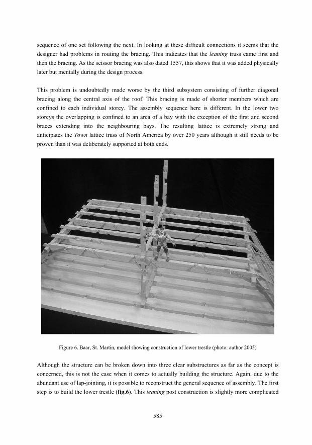
Figure 6. Baar, St. Martin, model showing construction of lower trestle (photo: author 2005) Although the structure can be broken down into three clear substructures as far as the concept is concerned, this is not the case when it comes to actually building the structure. Again, due to the abundant use of lap-jointing, it is possible to reconstruct the general sequence of assembly. The first step is to build the lower trestle (fig.6). This leaning post construction is slightly more complicated
585

to erect than the standing post. One side of posts can not be erected without massive supports as they are inherently off balance. We could not reconstruct the exact sequence of this first stage in great detail as much depends on the long-gone temporary supports. As soon as both sides are assembled, linked with straining beams and the angles braced in the cross-section and the longitudinal bracing is in place, the trestle becomes self-supporting. This can now be used to build up further members which become tied in to the whole structure keeping further supports to a minimum. As the spine bracing is deliberately constructed in several individual levels, it stands to reason, that it was intended to be erected in this manner. It therefore follows that the hanging posts and bracing were added next. Following this, the first set of diagonal braces in the trusses and frames were added as they too are designed for individual levels. The lap-joints again give the sequence allowing a storey by storey assembly. A further set can be added as well as the spine bracing at the next level, although it is quite possible that the next trestle could have been under construction (fig.7). Upon completion of the second storey, the lack of trestle and central post make it very unlikely that the upper spine was assembled as the next step. More importantly the purlin sits on the upper collar beams which implies that they and their supporting rafters were added first. With the rafters in place the final set of scissor braces were added completing the lower storeys. All that remained was to add the final spine bracing and the last small scissor braces, which just brace the upper level.
Figure 7. Baar, St. Martin, model showing completion of second storey (photo: author 2005)
586

The analysis revealed that the structure grew vertically, building all three substructures concurrently but relying on just one, the leaning trestle, for stability during the overall assembly. The design makes use of this trestle in two ways, firstly to give the final structure a means of transferring its loads directly to the outer walls and secondly to give stability to the structure during the assembly. This is state-of-the-art. Remarkable is the addition of two further bracing systems which are overlayed, allowing the structure to span 17 metres carrying a heavy ceiling. The spine bracing is geometrically laid out in regular intervals and constant angles producing an almost solid wall running the length of the roof. Great care was taken in its design. Against this the truss and frame scissor bracing is squeezed into the structure where possible. The braces are not always parallel to each other and end on certain members that are not the most suitable. This scissor bracing is technically a practical solution but not elegant. It suggests that it was perhaps an afterthought, although one still at the design stage. An alternative solution would be to beef up the sizes of the first two substructures. However the designer chose to superimpose a third and one ideal to the task of strengthening the trusses and frames as proven in countless other roofs which employed just this system. Evidently the designer had a great knowledge of other roof structures and innovatively mixed ideas together. Here is just a hint of what roof structure designers would be doing in the seventeenth century. THE MAIN ROOF OF THE CHURCH OF ST. XAVER IN LEOBEN (TOWN), STYRIA, AUSTRIA (1662 A.D.) Some two kilometres from the church of St. Andreas in Leoben-Goess is the church of St. Xaver in Leoben (town). The overall span is 21 metres, which covers nave and aisles (fig.8). The arcades between nave and aisles provide supports for the roof structure thus reducing the maximum free span to ca. 13 metres. Unlike the structure over Leoben-Goess the vaulting does not protrude into the roof space. The structure is divided into two clear structural systems. The lower storey consists of a trestle with standing (crown) posts, which are braced and stabilised with struts. The jointing is typically medieval with lap-jointing of the bracing to the sill beam and purlin. The barefaced laps are notched or dovetailed with straight sides. A couple of the dovetailed ends were curved as can be found in some medieval roofs. Unusual for this kind of standing trestle is the use of a straining beam tying the two purlins together. As at Leoben-Goess this assembly is further braced by truncated under-rafters.
The next storey is a state-of-the-art post-medieval construction system. The leaning posts are similar to those seen at Baar and form a polygonal arch with the staining beam spanning from outer wall to outer wall. The lower half of the post is reduced to a smaller cross-section than the upper, but the detailing of the connecting purlins and bracing is different. The soulaces are not lapped over the posts and beams but morticed and tenoned into the undersides. The purlins no longer have square or rectangular sections, but are angled to follow the line of the rafters, the upper faces being
587

horizontal. The lower- and outer faces are thus in the plane of the diagonal windbracing allowing for a much simpler connection. This idea is probably behind the decision to insert a sill beam at the foot of the leaning posts.
Figure 8. Main truss, frame, under-rafter bracing and longitudinal section (delineated: author 2005)
Like the braces under the leaning posts, the collar beams are also morticed and tenoned. It would appear that whilst lap-joints are easier to mark out when laying out a truss or frame, and even to assemble when laying flat, these advantages get lost when assembling the trusses vertically. As the simple roof frames increasingly incorporated more members forming complicated trusses, so it became necessary to change assembly practice. With the use of trestles in the structure, it was no longer possible to assemble single frames horizontally and pull them upright. The roof structure would be assembled three-dimensionally, the rafters being almost the last members to be erected rather than the first (fig.9). Adding members together with lap-joints in this way, means inserting them sideways, which has the great disadvantage of pushing against other members and loosening their joints. Mortice and tenon joints are easier to assemble on site as the members do not have to be attached from the side but from the ends. Possibly the realisation, that mortice and tenon joints are ideal for the erection of complicated three-dimensional structures came about after many years of experience with the difficulties of lap-joints. The change took place from about 1500 and swept from the south to the north over the following fifty years.
588
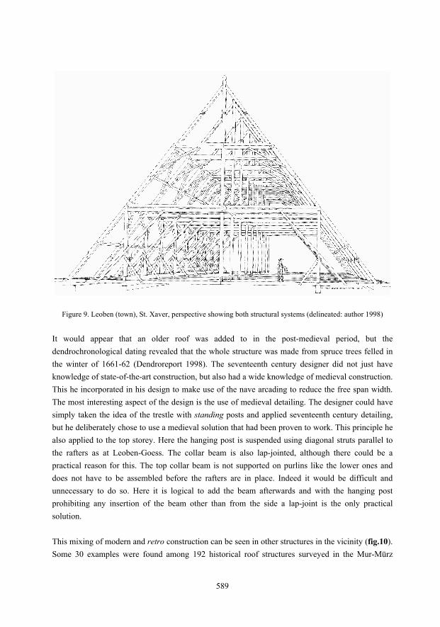
Figure 9. Leoben (town), St. Xaver, perspective showing both structural systems (delineated: author 1998) It would appear that an older roof was added to in the post-medieval period, but the dendrochronological dating revealed that the whole structure was made from spruce trees felled in the winter of 1661-62 (Dendroreport 1998). The seventeenth century designer did not just have knowledge of state-of-the-art construction, but also had a wide knowledge of medieval construction. This he incorporated in his design to make use of the nave arcading to reduce the free span width. The most interesting aspect of the design is the use of medieval detailing. The designer could have simply taken the idea of the trestle with standing posts and applied seventeenth century detailing, but he deliberately chose to use a medieval solution that had been proven to work. This principle he also applied to the top storey. Here the hanging post is suspended using diagonal struts parallel to the rafters as at Leoben-Goess. The collar beam is also lap-jointed, although there could be a practical reason for this. The top collar beam is not supported on purlins like the lower ones and does not have to be assembled before the rafters are in place. Indeed it would be difficult and unnecessary to do so. Here it is logical to add the beam afterwards and with the hanging post prohibiting any insertion of the beam other than from the side a lap-joint is the only practical solution.
This mixing of modern and retro construction can be seen in other structures in the vicinity (fig.10). Some 30 examples were found among 192 historical roof structures surveyed in the Mur-Mürz
589

valley in Styria in 1996 (Caston 1998, p. 530-534). Whilst two other structures had the same arrangement of a lower medieval design and an upper state-of-the-art, several other combinations also came to light. At least four examples were reversed with a medieval design over a state-of-the-art. A number were a mixture of both types intermingled, but the largest group is made up of copies of medieval structures. They can easily be mistaken for originals but the dendrochronological dating always reveals the truth. Some of these copies have the same curved ends to the dovetail laps as in Leoben on just one or two of the otherwise straight sided laps. This is how one can differentiate these copies from originals, as when an original medieval roof structure has these curves, then on all the joints, not just a few. It would seem that the designer or designers left the curved details as a signature citing their medieval examples.
Figure 10. Roof structures with retro design in the Mur-Mürz valley, Styria (delineated: author 2005) One particular example has an extraordinary detailed working of each beam (fig.10 – bottom right). The edges are bevelled and the ends of the bevels are further notched in elaborate carvings. This then is the mark of a master carpenter and shows that these roof structures were not thrown together by people with just a basic understanding of their craft but by professionals who were more than just craftsmen but also artists. The same applies to the design. The designer shows that he not only knows his own state-of-the-art construction techniques, but is also well versed in historic carpentry, so well that he understood their advantages and added them to his own repetoir. At present nothing is known of highly skilled and intelligent master builders, there is much to research here. The designers and carpenters responsible for further evolving the leaning trestle were similarly skilled
590

and highly intelligent. In addition their innovation allowed them to integrate new architectural ideas. THE MAIN ROOF OF CASTLE WEIßENSTEIN, POMMERSFELDEN, BAVARIA, GERMANY (1715 A.D.) An extreme example of this is the main roof of Castle Weißenstein in Pommersfelden built in the summer of 1715. The designer was faced with free spanning 24 metres, of which the middle two-thirds supported a heavy plastered ceiling. In addition his design had to incorporate a Mansard roof, that is with two different angled slopes joined at half height. Mansard roofs had only been built locally since circa 1700, but their design had been known in France half a century earlier. The designer could have copied the French construction as well as the appearance but stayed with the German tradition of building frames and trusses where the rafters contribute to the transmission of the structural forces.
Figure 11. Main truss, frame, under-rafter bracing and longitudinal section (delineated: author 2005) By the time of building the main roof as Castle Weißenstein, the development of the truss using the material wood had reached its peak. The basic elements in the roof structure are nothing new (fig.11). Two leaning trestles stacked on top of each other neatly allow two different angled slopes and hanging posts carry sill beams and purlins which in turn support the tie- and collar beams along their span. However, the overall size of the roof and the large weight increase due to the heavy
591

ceiling push the load carrying capacity of normal sized beams which can be cut from average to especially large trees to the limit and beyond. The designer resorted to engineering beams composited from normal beams to obtain the required sections of timber. It is the introduction of this technology into German roof trusses which is innovative although already tried elsewhere. This engineering can be best seen in the hanging posts made of oak, which are two halves vertically joined by stepping the contact surfaces with one another. Each half weighs approximately 0.85 metric tonnes (Caston 2005, p. 191). Similarly the three major sill beams which carry the lower tie-beams are two sections on top of each other joined using a series of interlocking teeth, designed to stop the two contact surfaces from slipping over each other and thus effectively doubling the overall section. These three beams do not just hang from the hanging posts but span the whole 36 metre length of the roof. They are supported at both ends by the outer walls and in the middle by a dividing wall. Thus there are two maximum bending moments at the quarter and three-quarter points plus an inverted one at the mid point. The beam designer took this into account and arranged for the teeth to change direction at these points anticipating the changing slip direction.
Figure 12. Pommersfelden, Castle Weißenstein, hanging posts (virtual model: Arnold Kreisel, Bamberg 1998)
The roof proved difficult to erect. Thanks to the interest of the owner in the building of his palace, his constant correspondence on the matter and the written building reports submitted by the foreman
592

and due to the fact that these documents survived destruction, a unique insite into the actual erection of the structure can be won from these sources (Caston 2005, p. 88-227). On the 8th of March 1715 the foreman reported that the carpenters had finished one side of the roof and were waiting for a crane to haul the members up into position. Towards the end of April nine hanging posts were in place, but the foreman reported that the job was progressing very slowly due to the hanging posts and as a consequence the costs were spiralling (fig.12). After the roof was completed at least two derrick-cranes and a windlass were left behind. Parts of these machines still survive today, stored in the roof (fig.13). The ratio of the radius of the winding axle to the turning wheels and the assumption that two workmen used there whole body weight gives the windlass a lifting capacity of 0.8 metric tonnes. Additional levers were also used to rotate the axle so that it was possible to lift over 1 metric tonne using four people. This is where the problems must have been, but not in the lifting of the individual halves of the hanging posts because the foreman mentioned nothing of lifting the tie beams, each weighing approximately 1 metric tonne. The problem must have been in pulling up the coupled beams into the vertical, each one weighing approximately 1.7 metric tonnes.
Figure 13. Pommersfelden, Castle Weißenstein, remains of windlass (photo: author 1998)
593
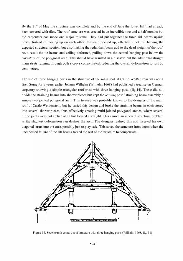
By the 21st of May the structure was complete and by the end of June the lower half had already been covered with tiles. The roof structure was erected in an incredible two and a half months but the carpenters had made one major mistake. They had put together the three sill beams upside down. Instead of closing up on each other, the teeth opened up, effectively not just halving the expected structural section, but also making the redundant beam add to the dead weight of the roof. As a result the tie-beams and ceiling deformed, pulling down the central hanging post below the curvature of the polygonal arch. This should have resulted in a disaster, but the additional straight main struts running through both storeys compensated, reducing the overall deformation to just 30 centimetres. The use of three hanging posts in the structure of the main roof at Castle Weißenstein was not a first. Some forty years earlier Johann Wilhelm (Wilhelm 1668) had published a treatise on German carpentry showing a simple triangular roof truss with three hanging posts (fig.14). These did not divide the straining beams into shorter pieces but kept the leaning post / straining beam assembly a simple two jointed polygonal arch. This treatise was probably known to the designer of the main roof of Castle Weißenstein, but he varied this design and broke the straining beams in each storey into several shorter pieces, thus effectively creating multi-jointed polygonal arches, where several of the joints were not arched at all but formed a straight. This caused an inherent structural problem as the slightest deformation can destroy the arch. The designer realised this and inserted his own diagonal struts into the truss possibly just to play safe. This saved the structure from doom when the unexpected failure of the sill beams forced the rest of the structure to compensate.
Figure 14. Seventeenth century roof structure with three hanging posts (Wilhelm 1668, fig. 11)
594
In this case the designer could not just take a tried and tested solution and increase its size, but had to redesign various details. In order to guarantee structural integrity he ingeniously supplied additional safety members, which as it turned out were wholly justified. Although much is known about the architects, the site foreman, the progress of work and costs, who the designer of the roof construction was, remains a mystery. Plans of other contemporary buildings with large roof structures drawn by architects show roofs which differ from those actually found in the buildings. Whilst it can be assumed that architects had some rudimentary understanding of these structures, there is no evidence that they were capable of producing the final detailed design themselves, including the sizes of the individual members. It seems that this was left to an unknown engineer or craftsman, in the case of Castle Weißenstein probably a master carpenter whose name was never mentioned in the sources. SUMMARY Each of the above mentioned roof structures document the developments of wooden roof structure design in Central Europe at a time of gradual but continuous change. They are not just representatives of a particular stage of development of a constructional solution but reflect individual responses to the problems which had to be confronted at the moment of conception. I believe that a small insight into the character of the designer can be interpreted by comparing these individual designs with the general state-of-the-art. Around 1510 the designer of the main roof at St. Andreas, Leoben-Goess seems to have been a man with great practical building experience on site and concerned with safety for those actually involved in building the structure. His choice of a conservative design suggests that he was wise and possibly elderly. In 1557 the designer of the main roof at St. Martin in Baar superimposed three different substructures upon one another. Each substructure was a proven design in its own right. This designer showed that he had a great knowledge of other roof structures and successfully integrated three different concepts together to strengthen the trusses and frames. A similar understanding of different structural concepts was demonstrated by the designer of of the main roof at St. Xaver, Leoben (town). The design (shortly before 1662) shows the parallel use of state-of-the-art construction and historic techniques, each used to their advantage. This reveals an intelligent, well informed craftsman, who possibly played or experimented with his knowledge. Around 1715, the designer of the main roof at Castle Weißenstein in Pommersfelden daringly modified a standard design to accommodate the structural requirements of building an oversized roof structure. This very nearly resulted in failure through no fault of his own but it was his concern for and understanding of structural integrity which lead him to compensate in advance for design problems and ultimately save the structure from destruction. Each unknown master left a part of himself in his creation and this reveals not just how unique each structure is, but also how different each designer was. Thousands more unique roof structures await
595

their documentation and analysis in an effort to explain how these fabulous structures developed in Central Europe and with them the possibility of discovering many more personalities recorded in them. The study of historic building construction is also the study of the human being. ACKNOWLEDGEMENTS A post-doctoral research grant given to the author by the Deutsche Forschungsgemeinschaft (German Research Council) in 1996 and in conjunction with Bamberg University, Germany made the study of three of these roofs possible. My thanks to those who chose to sponsor me. I also wish to acknowledge the efforts of many of the students at Bamberg University, who spent many hours recording the fabric of the main roof of Castle Weißenstein and the efforts of many of the students at Neubrandenburg University of Applied Sciences, Germany who helped build the wooden study models. Special thanks to Arnold Kreisel, Bamberg for his virtual study model and to the owners of the above mentioned structures for their permission for me to visit, document and analyse them. REFERENCES Manuscripts: Canton Conservation Office, Canton Zug (Switzerland) Dendroreport, 1994. Dendrochronologischer Bericht vom 28 Januar and 14 April 1994 (Report by Dendrolaboratory Heinz and Christina Egger, CH-3067 Boll) Bamberg University, Institute of Building Conservation (Germany) Dendroreport, 1998. Dendrochronologischer Bericht Leoben, Stadtpfarrkirche vom 8 June 1998 (Report by Dendrolaboratory, Bamberg University, D-96049 Bamberg) Baumeister-Zeitung, 1930. “Kirche in Baar und Zimmerhandwerk“, Hoch- und Tiefbau, Schweizer Baumeister-Zeitung, A0 XXIX, Nr. 5, pp. 34-39. Printed Sources: Binding, G, 1991. Das Dachwerk auf Kirchen im deutschen Sprachraum vom Mittelalter bis zum 18. Jahrhundert, Munich: Deutscher Kunstverlag. Birchler, L, 1934. Die Kunstdenkmäler des Kantons Zug, Band 1, Basel. Caston, P, 1998. “Dachwerkstopographie für die Steiermark – Ein Survey der historischen Dachwerkskonstruktionen in der Mur-Mürz-Furche“, Österreichische Zeitschrift für Kunst und Denkmalpflege, LII, Nr. 3/4, pp. 518-536.
596

Caston, P, 2005. Das Langhausdachwerk von St. Andreas, Leoben-Göß und das Mittelbaudachwerk von Schloss Weißenstein Pommersfelden – Studien des Fachbereichs Bauingenieur- und Vermessungswesen der Hochschule Neubrandenburg zu historischen Tragwerken, Neubrandenburg: Neubrandenburg University of Applied Sciences Press. Grünenfelder, J, 1999. Die Kunstdenkmäler des Kantons Zug, Band 1, Basel: Wiese Verlag. Ostendorf, F, 1908. Die Geschichte des Dachwerks, Leipzig: Teubner Verlag (Reprint 1987 Hannover: Th. Schäfer Verlag). Wilhelm, J, 1668. Architectura Civilis, Nuremberg: Paul Fuerstens Verlag (Reprint 1989 Hannover: Th. Schäfer Verlag).
597