Embed Size (px)
Citation preview

Abstract—A finite element procedure for three-dimensional
adaptive trusses using shape memory alloys is formulated in the present study, in which the extended form of Brinson’s constitutive equation considering asymmetric tensile and compressive behaviors is expressed in a tangentially incremental form. The validity of the present computational modeling is demonstrated by conducting numerical studies for the superelastic, shape memory behaviors of two-bar, nine-bar and twenty eight-bar adaptive trusses subjected to load and temperature changes. The proposed computational procedure is expected to be useful for the optimum design of the adaptive trusses with shape memory alloy bars.
Index Terms—Finite Element Method, Adaptive Structure, Framed Structure, Shape Memory Materials, Smart Materials
I. INTRODUCTION
Adaptive truss structures, which can control their mechanical properties such as stiffness and deformation, are applicable to parabola antennas and space structures. Wire actuators and shape memory alloys (SMAs) have been studied as control mechanisms [1], [2]. Development of a practical computational tool is necessary for the efficient design of adaptive trusses.
A finite element analysis procedure for the adaptive trusses using SMA members is formulated in the present study. Its validity is illustrated by some numerical examples. Bandeira et al. [2] conducted finite element analysis of the adaptive trusses using SMA members, employing the constitutive equation by Paiva et al. [3]. Their analysis is based on the incremental constitutive equation in an initial stress form, only for two-dimensional trusses and neglects asymmetry of the tensile and the compressive behavior.
The phenomenological and simple constitutive equation given by Brinson [4] is extended to consider the asymmetric tensile and compressive behavior [5] in the present finite element analysis procedure. The numerically stable, incremental constitutive equation in a tangential stiffness form [6] is derived and applied to the incremental finite element analysis of general three-dimensional adaptive trusses.
A finite element analysis procedure for SMA trusses is formulated in Section 2. Results of the finite element
Manuscript received December 28, 2010. Y. Toi is with the Institute of Industrial Science, University of Tokyo,
Komaba, Meguro-ku, Tokyo, 153-8505 Japan (phone: 03-5452-6178, fax: 03-5452-6180, e-mail: [email protected]) .
K. Tsukamoto was with the Graduate School, University of Tokyo, Komaba, Meguro-ku, Tokyo, 153-8505 Japan.
analysis of adaptive trusses are described in Section 3. Section 4 contains concluding remarks.
II. FINITE ELEMENT ANALYSIS PROCEDURE OF SHAPE
MEMORY ALLOY TRUSSES
A. Constitutive Equation
The mechanical property of SMAs is schematically shown in Fig. 1. Fig. 1(a) and Fig. 1(b) are the stress-strain curve and the relation between critical transformation stresses and temperature respectively, in which the superelastic behavior (bold line arrows) and the shape memory effect behavior (broken line arrows) are shown.
In Fig. 1, the following notations are used: ; the stress, ; the strain, T ; temperature, cr
f and crs ; the finishing
and starting critical stress for martensite transformation, fM
and sM ; the finishing and starting temperature for martensite transformation, sA and
fA ; the starting and finishing temperature for austenite transformation. In Fig. 1(b), cr
f and crs are assumed to be constant in the case of
sMT according to Brinson’s formulation [4]. sMC and
fMC are the gradients in the relations between the finishing and starting critical stress for martensite transformation and the temperature.
sAC and fAC are the gradients in the
relations between the starting and finishing critical stress for austenite transformation and the temperature.
MMM CCCfs and
AAA CCCfs are assumed in the
present analysis. When the stress is loaded and unloaded at the temperature
lower than fA (
fssf AATMM here) in Fig. 1(b), the inverse (austenite) transformation for the strain generated by the martensite transformation does not finish and leaves the residual strain ( res ) as shown in Fig. 1(a). Heating to the temperature higher than
fA , the austenite transformation finishes and the strain disappears as shown in Fig. 1(a). Even when heating sufficiently without unloading of the stress, the strain generated by the martensite transformation disappears although the elastic strain remains. This is the outline of the shape memory effect. In the case of fAT , the superelastic behavior as shown in Fig. 1(a) takes place as the inverse transformation finishes by the unloading.
The one-dimensional stress-strain relation of SMAs is generally expressed by the following equation [4]:
Computational Modeling of Adaptive Trusses with
Shape Memory Alloy Members
Yutaka Toi and Kazunori Tsukamoto
Engineering Letters, 19:1, EL_19_1_06
(Advance online publication: 10 February 2011)
______________________________________________________________________________________

)( 0
00000
TT
EE SS
(1)
where E ; Young’s modulus, ; the transformation coefficient, S ; the stress-induced martensite volume fraction, ; the elastic thermal coefficient, T ; temperature. The subscript “0” indicates initial values. is expressed as follows:
EL (2)
where L is the maximum residual strain. Young’s modulus E is a function of the martensite
volume fraction , which is given by the following equation:
)( ama EEEE
(3)
where mE and aE are Young’s modulus of the martensite phase and the austenite phase, respectively.
The martensite volume fraction is expressed by the following equation:
TS (4)
where T is the temperature-induced martensite volume fractioin. , S and T are functions of the temperature T and the stress .
In order to consider the asymmetric tensile and compressive behavior, the evolution equations for , S and T are expressed by Drucker-Prager’s equivalent stress in which the hydrostatic pressure term is added to von Mises’ equivalent stress.
HMeq
DPeq 3
(5)
where is a material parameter. H is the hydrostatic pressure given by the following equation:
zyxH 3
1 (6)
In one-dimensional case, the equivalent stress of eq. (5) is expressed as follows:
DPeq (7)
Substituting eq. (7) into the evolution equation for , S and T given by Brinson [4], the evolution equation for the martensite and the austenite transformation can be obtained.
The stress-strain relation given in eq. (1) can be expressed in a differential form as follows:
dTdT
Td
dTT
dd
dE
dE
dEddT
Td
d
dE
dTddEddEd
SS
S
sS
(8)
An incremental form of the stress-strain relation can be derived as follows:
dTTTd
dE
dE
d
Td
dEEd
dd
dE
dE
d
d
dE
SS
SS
1
(9)
(a) Superelastic behavior and shape memory effect
(b) Critical stresses for transformation vs. temperature
Fig.1 Mechanical properties of shape memory alloys
Therefore the stress-strain relation for the finite element
analysis can be written as follows:
seseD (10)
Details of eq. (10) are given in Ref. [5].
B. Finite Element Analysis Procedure
Based on the total Lagrangian approach [6], the finite element analysis procedure for a truss element is formulated assuming finite deformation.
Seeing Fig. 2, the displacement field in the three-dimensional truss element is assumed by the following equations:
ji ul
zu
l
zzu
1
(11a)
ji vl
zv
l
zzv
1 (11b)
ji wl
zw
l
zzw
1 (11c)
where zu and zv are the lateral displacements. zw is the axial displacement.
Engineering Letters, 19:1, EL_19_1_06
(Advance online publication: 10 February 2011)
______________________________________________________________________________________

The incremental strain-displacement relation is assumed as follows:
22
2
1
dz
vd
dz
ud
dz
vd
dz
dv
dz
ud
dz
du
dz
wdz
(12)
Equation (12) considers the nonlinear terms with respect to the lateral displacements, neglecting the nonlinear term with respect to the axial displacement.
The relation between the linear component of the strain increment and the nodal displacement increments is expressed in a matrix form as follows:
dBBdB L 0
(13)
where the following notations are used: B ; the strain-nodal displacement matrix, 0B ; the strain-nodal displacement matrix without influence of the initial displacements, LB ; the strain-nodal displacement matrix with the influence of the initial displacements, d ; the nodal displacement increment vector ( jjjiii wvuwvud ).
The finite element formulation based on the virtual work principle using the constitutive equation outlined in Subsection Ⅱ.A leads to the incremental element stiffness equation as follows:
RseGL fffukkk 0 (14)
where
eV
)(se
T dVBDBk 0000 (15)
eV
)(Lse
TLse
TLLse
TL dVBDBBDBBDBk 0
00
(16)
eV
)(TG dVGSGk 0
(17)
eV sese
T
se dVDBf )0( (18)
The following notations are used in the equations: 0k ; the incremental stiffness matrix, Lk ; the initial displacement matrix, Gk ; the initial stress matrix, f ; the external force increment vector, sef ; the apparent external force increment vector due to the superelasticity and the shape memory effect, Rf ; the unbalanced force vector, seD ; the superelastic stress-strain matrix, se ; the initial strain vector due to the superelasticity and the shape memory effect, G ; the gradient matrix, S ; the stress matrix, eV ; the element volume.
The present formulation is applicable to the simulations of the superelastic and shape memory effect responses of the general three-dimensional adaptive trusses using SMA members subjected to an arbitrary load and temperature history.
X
Ziw
juiu
jwl
ivjv
Fig.2 Truss element
Table 1 Material constants for the SMA
Elastic modulus
Ea=54 GPa
Em=42 GPa
ES=200 GPa (steel)
Transformation temperatures
Mf=10 ℃
Ms= 20 ℃
As= 46.25 ℃
Af=56.25 ℃
Transformation constants
CM=9.25 MPa/℃
CA=8.0 MPa/℃
σscr=50 MPa
σfcr=150 MPa Maximum residual
strain εL=0.055
0
200
400
600
800
1000
0 0.01 0.02 0.03 0.04 0.05 0.06 0.07 0.08
Stress (Mpa)
ε
80℃ NUMERICAL
80℃ EXPERIMENTAL
0
200
400
600
800
1000
0 0.02 0.04 0.06 0.08
Stress (MPa)
ε
100℃ NUMERICAL
100℃ EXPERIMENTAL
Fig.3 Stress-strain curves at 80℃(upper) and 100℃(lower)
Engineering Letters, 19:1, EL_19_1_06
(Advance online publication: 10 February 2011)
______________________________________________________________________________________

III. FINITE ELEMENT ANALYSIS OF ADAPTIVE TRUSSES
A. Identification of Material Constants
The material constants of the SMA defined in Subsection 2.1 have been determined as shown in Table 1, based on the experimental results by Tobushi et al. [7]. In Table 1, sE is Young’s modulus of steel which is assumed to be linearly elastic. It is assumed that 15.0 or 0 in eq. (7). Figure 3 shows the identified stress-strain curves at 80℃ and 100℃ compared with the experimental results by Tobushi et al. [7].
B. Two-Dimensional Two-Bar Truss
The two-dimensional two-bar adaptive truss as shown in Fig. 4 has been analyzed by using the material constants identified in Subsection Ⅲ.A. The members ① and ② are both SMA with a cross section of 1cm2. The load F(t) increases at t=0~1.0 and keeps constant at t=1.0~2.0. The temperature keeps a constant value smaller than
fM at t=0~1.0, rises over
fA at t=1.0~2.0 and returns back at t=2.0~3.0. The present analysis considers the asymmetric tensile and compressive behavior, assuming 15.0 in eq. (7).
0
20
40
60
80
100
120
140
0 1 2 3
T(℃)
Time
-30
-25
-20
-15
-10
-5
0
0 1 2 3
F(KN)
Time
Fig.4 Two-bar truss
Fig.5 Time-history of displacement for 2-bar truss
Fig.6 Time-history of stress for 2-bar truss
Fig.7 Stress-strain curve for 2-bar truss
Figure 5 is the time-history of the vertical displacement at
the loading point. At t=0~1.0, the displacement due to the martensite transformation of the SMA members is generated with an increase of the load. At t=1.0~2.0, the displacement generated by the martensite transformation disappears, leaving the elastic deformation, due to the inverse (austenite) transformation with the temperature rising. At t=2.0~3.0, the martensite transformation takes place again, generating the displacement. There is little difference between the results of the small deformation and the large deformation analysis, as the displacement is not so large.
Figure 6 is the time-history of the stress in each member. The stress level rises by the load increase at t=0~1.0, being almost constant later. Tensile stress takes place in the member ①, while compressive stress is generated in the
Engineering Letters, 19:1, EL_19_1_06
(Advance online publication: 10 February 2011)
______________________________________________________________________________________
member ②. The stresses in the member ① (tensile side) and the member ② (compressive side) are completely symmetric in the small deformation analysis. However, in the finite deformation analysis, the stresses in the member ① (tensile side) and the member ② (compressive side) are asymmetric as the finite deformation effect generates positive stress variation, which can also be observed in Fig. 7.
Figure 7 shows the stress-strain curves of the members. In both members, the martensite transformation finishes by the load increase at t=0~1.0. The strains vanish by the inverse (austenite) transformation due to the temperature rise at t=1.0~2.0. The strains are again generated by the martensite transformation due to the temperature drop at t=2.0~3.0. As
15.0 is assumed, the absolute values of the starting and finishing critical stresses for martensite transformation in the member ② (compression) are about 30% higher than those in the member ① (tension).
C. Two-Dimensional Nine-Bar Truss
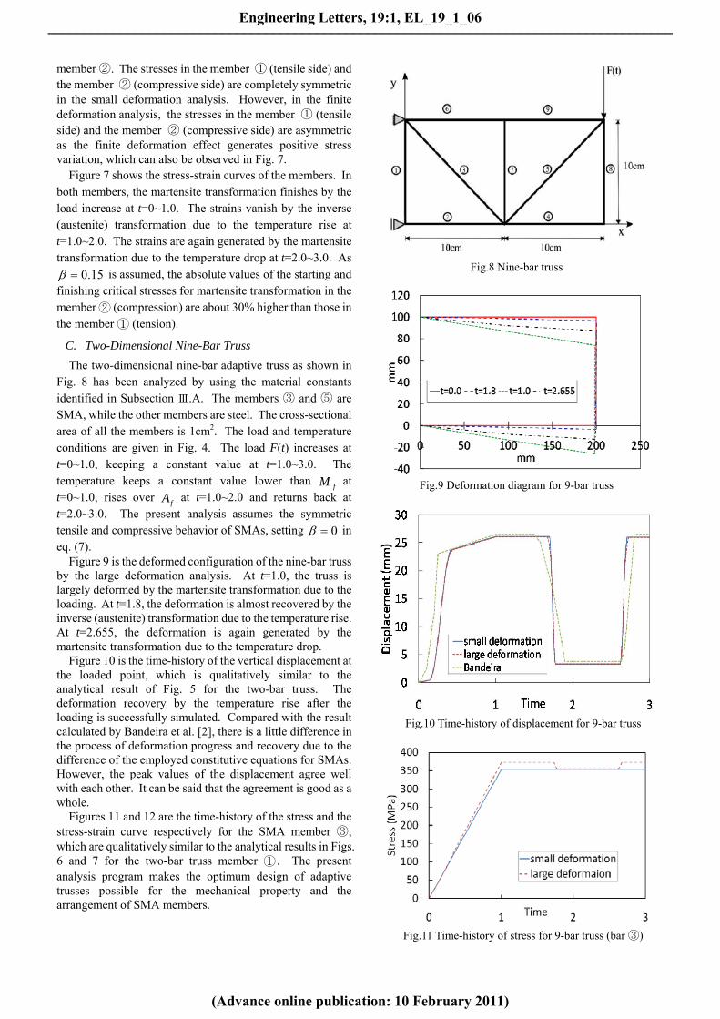
The two-dimensional nine-bar adaptive truss as shown in Fig. 8 has been analyzed by using the material constants identified in Subsection Ⅲ.A. The members ③ and ⑤ are SMA, while the other members are steel. The cross-sectional area of all the members is 1cm2. The load and temperature conditions are given in Fig. 4. The load F(t) increases at t=0~1.0, keeping a constant value at t=1.0~3.0. The temperature keeps a constant value lower than
fM at t=0~1.0, rises over
fA at t=1.0~2.0 and returns back at t=2.0~3.0. The present analysis assumes the symmetric tensile and compressive behavior of SMAs, setting 0 in eq. (7).
Figure 9 is the deformed configuration of the nine-bar truss by the large deformation analysis. At t=1.0, the truss is largely deformed by the martensite transformation due to the loading. At t=1.8, the deformation is almost recovered by the inverse (austenite) transformation due to the temperature rise. At t=2.655, the deformation is again generated by the martensite transformation due to the temperature drop.
Figure 10 is the time-history of the vertical displacement at the loaded point, which is qualitatively similar to the analytical result of Fig. 5 for the two-bar truss. The deformation recovery by the temperature rise after the loading is successfully simulated. Compared with the result calculated by Bandeira et al. [2], there is a little difference in the process of deformation progress and recovery due to the difference of the employed constitutive equations for SMAs. However, the peak values of the displacement agree well with each other. It can be said that the agreement is good as a whole.
Figures 11 and 12 are the time-history of the stress and the stress-strain curve respectively for the SMA member ③, which are qualitatively similar to the analytical results in Figs. 6 and 7 for the two-bar truss member ① . The present analysis program makes the optimum design of adaptive trusses possible for the mechanical property and the arrangement of SMA members.
Fig.8 Nine-bar truss
Fig.9 Deformation diagram for 9-bar truss
Fig.10 Time-history of displacement for 9-bar truss
Fig.11 Time-history of stress for 9-bar truss (bar ③)
Engineering Letters, 19:1, EL_19_1_06
(Advance online publication: 10 February 2011)
______________________________________________________________________________________

Fig.12 Stress-strain curve for 9-bar truss (bar ③)
D. Three-Dimensional Twenty Eight-Bar Truss
The three-dimensional twenty eight-bar adaptive truss as shown in Fig. 13 has been analyzed by using the material constants identified in Subsection Ⅲ.A. The left and right side structures of the present truss, which are similar to the two-dimensional nine-bar truss in Fig. 7, are connected with the upper and lower side members. The members ②, ④, ⑩
and ⑫ are SMA, while the others are steel. The cross-sectional area of all the members is 1cm2. The loading and temperature conditions are given in Fig. 4. In the present example, the symmetric tensile and compressive behavior is assumed by setting 0 in eq. (7).
Figure 14 shows the time-history of the vertical displacements at the loaded point A and the adjacent point B shown in Fig. 13. The characteristics as an adaptive truss can be understood from the time-history of the displacement (WA) at the loaded point A. The displacement (WB) at the point B is not generated in the small deformation analysis, while a little displacement occurs at the point B in the large deformation analysis, as an axial force is generated in the upper and lower side members.
Fig. 15 is the time-history of the stresses in the SMA members ②, ④, ⑩ and ⑫ by the finite deformation analysis. In the members ⑩ and ⑫, a small stress is generated by the influence of finite deformation.
Figure 16 is the stress-strain curves for the SMA members ②, ④, ⑩ and ⑫. The stress-strain curves for the member ⑩ and ⑫ are overlapped on those for the members ② and ④.
Fig.13 Twenty eight-bar truss
Fig.14 Time-history of displacement for 28-bar truss
Fig.15 Time-history of stress for 28-bar truss
Fig.16 Stress-strain curve for 28-bar truss
IV. CONCLUSION
In the present paper, which is the revised version of Ref. [8], the incremental finite element analysis procedure has been formulated for the three-dimensional adaptive trusses using SMA members by deriving the tangential form of incremental constitutive equation based on Brinson’s constitutive equation extended to consider the asymmetric tensile and compressive behavior.
The formulation has been applied to the superelasticity and shape memory effect behavior analysis of the two-dimensional two-bar, nine-bar and three-dimensional twenty eight-bar adaptive truss using SMA members. The validity and usefulness of the proposed computational algorithm has been demonstrated by the comparison with the existing numerical solutions and the qualitative
B
A ⑫
⑩
②
④
Engineering Letters, 19:1, EL_19_1_06
(Advance online publication: 10 February 2011)
______________________________________________________________________________________

consideration. The present computational procedure, which can simulate
the superelasticity and shape memory effect responses of general three-dimensional trusses using SMA members subjected to an arbitrary load and temperature history, is expected to contribute to the rational and efficient design and development of adaptive trusses.
REFERENCES
[1] Hanahara, K. and Tada, Y., Adaptive Truss by Means of Wire Member
Actuators, CD-ROM Proceedings of Dynamics and Design Conference,
JSME No.03-7 (2003).
[2] Bandeira, E. L. et al., Finite Element Analysis of Shape Memory Alloy
Adaptive Trusses with Geometrical Nonlinearities, Arch. Appl.. Mech.,
Vol.76 (2006), pp.133-144.
[3] Paiva, A. et al., A Constitutive Model for Shape Memory Alloys
Considering Tensile-Compressive Asymmetry and Plasticity, Int. J. of
Solids and Structures, Vol.42, No.11-12 (2005), pp.3439-57.
[4] Brinson, L. C., One-Dimensional Constitutive Behavior of Shape
Memory Alloys: Thermomechanical Derivation with Non-Constant
Material Functions and Redefined Martensite Internal Variable, J. of
Intelligent Material Systems and Structures, Vol 4, No.2 (1993),
pp.229-242.
[5] Toi, Y. et al., Finite Element Analysis of Superelastic, Large
Deformation Behavior of Shape Memory Alloy Helical Springs,
Computers and Structures, Vol.82, No.20-21 (2004), pp.1685-1693.
[6] Toi, Y., A Course on Computational Solid Mechanics (Modeling and
Simulation of Materials and Structures), (2008), pp.56-83, Corona
Publishing Company Ltd.
[7] Tobushi, H. et al., Deformation Behavior of Ni-Ti Shape Memory
Alloy Subjected to Variable Stress and Temperature, Continuum Mech
Thermodyn, 3 (1991), pp.79-93.
[8] Toi, Y. and Tsukamoto, K., Finite Element Analysis of Adaptive
Trusses with Shape Memory Alloy Members, Lecture Notes in
Engineering and Computer Science: Proceedings of The World
Congress on Engineering and Computer Science 2010, WCECS 2010,
20-22 October, 2010, San Francisco, USA, pp.15-20.
Engineering Letters, 19:1, EL_19_1_06
(Advance online publication: 10 February 2011)
______________________________________________________________________________________


![ADAPTIVE HYSTERESIS CURRENT CONTROL OF INVERTER · PDF fileADAPTIVE HYSTERESIS CURRENT CONTROL OF INVERTER FOR SOLAR ... (ACMC), Sliding Mode Control (SMC) [13] ... all points of the](https://img.pdfslide.us/doc/110x75/5a87d0157f8b9a9f1b8e0a96/adaptive-hysteresis-current-control-of-inverter-hysteresis-current-control-of.jpg)