Embed Size (px)
Citation preview
10th International Conference on Fracture Mechanics of Concrete and Concrete StructuresFraMCoS-X
G. Pijaudier-Cabot, P. Grassl and C. La Borderie (Eds)
HIGH STRAIN-RATE RESPONSE OF UHPFRC IN SUPPORT OF IMPACTRESISTANT STRUCTURAL DESIGN
EZIO CADONI∗, DANIELE FORNI∗
∗DynaMat Laboratory, University of Applied Sciences of Southern SwitzerlandCanobbio, Switzerland
e-mail: [email protected]
Key words: High Strain Rate, UHPFRC, Modified Hopkinson Bar
Abstract. Understanding the dynamic response of Ultra High Performance Fibre Reinforced Con-crete (UHPFRC) is one of the most critical issue in the design of protective structures and criticalinfrastructures which need to withstand explosion or impact actions. These dynamic phenomenacause a different response of the cementitious materials which must be carefully evaluated at the de-sign stage. In the frame of a research aimed to design special shields to protect buildings or criticalinfrastructures from the effect of IEDs (Improvised Explosive Devices) a comprehensive study onUHPFRCs’ dynamic response has been developed. In this paper are described the different testingset-ups used to analyse the dynamic behaviour of the UHPFRC materials in different failure modes(tension, compression, shear) at high strain-rate.
1 INTRODUCTION
Critical infrastructures (such as particularbuildings, tunnels and bridges) have a fairlyhigh vulnerability to the effects of the Impro-vised Explosive Devices (IED). To protect in-frastructure elements from the effects of IEDprotective structures, such as reinforced con-crete shields, are often used. These elementsare able to withstand overloads caused by stresswaves generated by blast and dissipate the hugeamount of energy in deformation preventingno-desired effects such as spalling. As conse-quence, the wave propagation provokes, in theinner part, tension waves that usually can ex-ceed the material strength. Thus some concretefragments can be ejected and projected at highvelocities causing lethal threats to people andserious damage to internal equipment. When acritical structure has been designed without anyblast protection, it is necessary to improve itsresistance capacity by means of a retrofitting.Usually, it consists of an additional structural
member attached to the existent structure.
Ultra-High Performance Fibre-ReinforcedConcrete (UHPFRC) is an advanced cemen-titious composite material combining cement-based matrix with a low water-to-binder ratioand reinforcing fibres (usually≥2% in volume).The introduction of fibres leads to obtain a duc-tile behaviour with large dissipation of energytogether with outstanding strength. Thanks tothese characteristics UHPFRC is a promisingmaterial for construction of protective struc-tures. Indeed, several researcher groups devel-oped solutions for protective element based onUHPFRC against fast transient loads such asimpact, blast, or contact charges. Despite theconsiderable interest aroused, many aspects inthe mechanical response of these materials mustbe still deeply investigated, in particular in thehigh-strain rate regime. In order to properly de-sign a protective structure fast transient load-ing events, caused by impact or blast, need tobe understood. In particular the knowledge of
1

Ezio Cadoni and Daniele Forni
the material response at these loading regimesis fundamental.
This paper focuses on mechanical charac-terisation at high strain rate of the UHPFRCmaterials and presents the experimental tech-niques used. These results were obtained inthe frame of a research aimed to protect build-ings or critical infrastructures from the effect ofIEDs (Improvised Explosive Devices) by meansof a series of sandwich systems, combining re-inforced concrete and UHPFRC layers. This re-search conducted in Switzerland and supportedby the Federal Department of Defence, CivilProtection and Sport – armasuisse Science andTechnology involved the DynaMat Laboratoryof the University of Applied Sciences of South-ern Switzerland (Lugano) for the study of thedynamic behaviour of several UHPFRCs in ten-sion, compression, shear.
2 MATERIALSThe UHPFRCs investigated are commercial
products characterised by outstanding strengthand durability. They are cementitious materialmixes composed of micro silica, cement, quartzsand, water, and super plasticisers. As re-sult the matrixes obtained are extremely durableand highly resistant (equivalent water/binderratio = 0.17). By adding a high percentageof steel micro-fibres reinforcement (generally≥3% in volume) excellent mechanical prop-erties such as very high compression (180-210 MPa), flexural (40-50 MPa), and tensilestrength (8-12 MPa) can be reached. The elas-tic modulus is usually around 50 GPa. Otherrelevant characteristics are: high ductility, highwater and gas impermeability, very high resis-tance to chloride penetration, carbonation, acidattack and abrasion. In this research three UH-PFRCs mixes, having 3%, 4% and 5% fibrecontent, were investigated. High carbon straightfibres 10 mm and 13 mm long with a 0.16 mmdiameter (aspect ratio lf/df equal to 62.50 and81.25) were used. To study the direct tensionbehaviour cylindrical specimens with a diame-ter of 20 mm and diameter/height ratio equal to1 were used. This specimen size can be consid-
ered large enough to reasonably represent thebehaviour of composite materials containing fi-bres (at least 70 fibres per sample). All speci-mens were pre-notched (notch/radius = 0.15) inorder to prevent multiple fractures.The quasi-static tests were carried out by meansof a standard Zwick/Roell machine having max-imum load capacity of 50kN. Stroke was con-sidered as feedback parameter during the tests.The displacement rate imposed during the testswas equal to 5·10−5 mm/s. The average ten-sile strength of UHPFRC with 5% fibre con-tent was 9.7±1.9 MPa, while the correspon-dent tensile strength of the matrix (UHPC) was8.0± 0.5 MPa. The number of fibres in thecross–section was 114±28. In the quasi-staticcompression test the strength was 167±25MPa.The results of the UHPFRC with 3% and 4%fibre content can be found in [1].
3 DYNAMIC TESTING SET-UPSThe mechanical characterisation of material
is of critical importance to correctly design anystructures. In fact, only giving true informationon the material behaviour in different loadingmodes and in a wide range of strain rate, the ma-terial constitutive models can be properly cali-brated [2]. A brief description of the experi-mental set-ups used in the research is given inthe following.
3.1 Direct tensile testIn order to study the behaviour in tension of
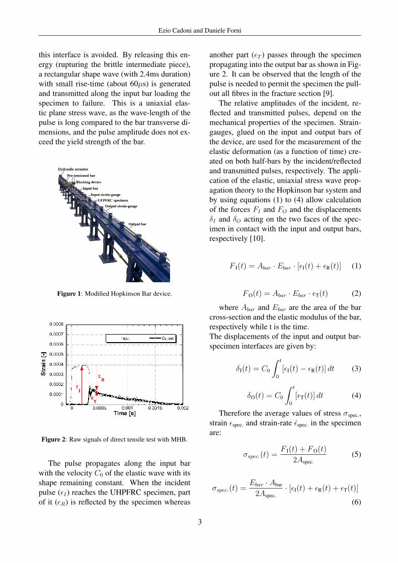
UHPFRC a Modified Hopkinson Bar [3–8] hasbeen used (Figure 1). It consists of two cir-cular aluminium bars, having a diameter of 20mm, with a length of 3 and 6 m for input andoutput bar, respectively. The UHPFRC spec-imen was glued to the input and output barsby an epoxy resin. The pretensioned bar wasa high strength steel (6m length) connected tothe input bar. By pulling one end (the other isconnected with a blocking system) of the pre-tensioned bar is possible to store elastic en-ergy in it. The pretensioned bar is connectedwith the incident bar and has the same acous-tical impedance so the spurious reflections in
2
Ezio Cadoni and Daniele Forni
this interface is avoided. By releasing this en-ergy (rupturing the brittle intermediate piece),a rectangular shape wave (with 2.4ms duration)with small rise-time (about 60µs) is generatedand transmitted along the input bar loading thespecimen to failure. This is a uniaxial elas-tic plane stress wave, as the wave-length of thepulse is long compared to the bar transverse di-mensions, and the pulse amplitude does not ex-ceed the yield strength of the bar.
Figure 1: Modified Hopkinson Bar device.
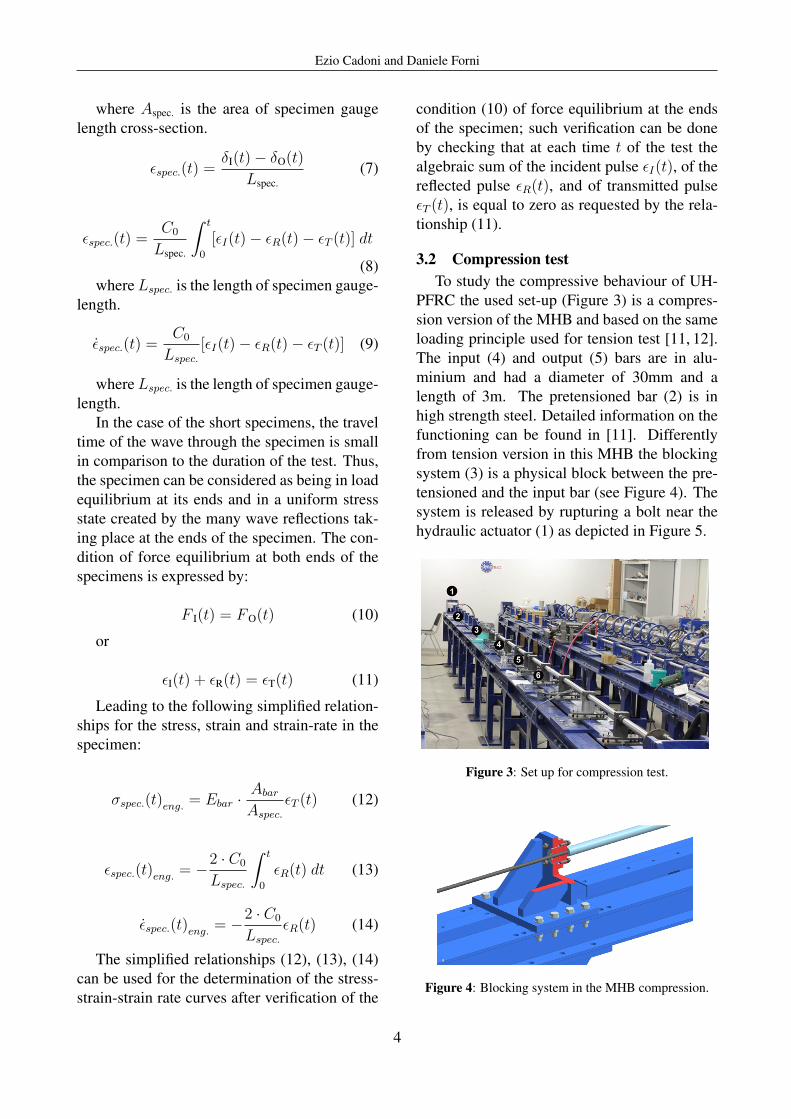
Figure 2: Raw signals of direct tensile test with MHB.
The pulse propagates along the input barwith the velocity C0 of the elastic wave with itsshape remaining constant. When the incidentpulse (εI) reaches the UHPFRC specimen, partof it (εR) is reflected by the specimen whereas
another part (εT ) passes through the specimenpropagating into the output bar as shown in Fig-ure 2. It can be observed that the length of thepulse is needed to permit the specimen the pull-out all fibres in the fracture section [9].
The relative amplitudes of the incident, re-flected and transmitted pulses, depend on themechanical properties of the specimen. Strain-gauges, glued on the input and output bars ofthe device, are used for the measurement of theelastic deformation (as a function of time) cre-ated on both half-bars by the incident/reflectedand transmitted pulses, respectively. The appli-cation of the elastic, uniaxial stress wave prop-agation theory to the Hopkinson bar system andby using equations (1) to (4) allow calculationof the forces FI and FO and the displacementsδI and δO acting on the two faces of the spec-imen in contact with the input and output bars,respectively [10].
F I(t) = Abar · Ebar · [εI(t) + εR(t)] (1)
FO(t) = Abar · Ebar · εT(t) (2)
where Abar and Ebar are the area of the barcross-section and the elastic modulus of the bar,respectively while t is the time.The displacements of the input and output bar-specimen interfaces are given by:
δI(t) = C0
∫ t
0
[εI(t)− εR(t)] dt (3)
δO(t) = C0
∫ t
0
[εT(t)] dt (4)
Therefore the average values of stress σspec.,strain εspec. and strain-rate ε̇spec. in the specimenare:
σspec.(t) =F I(t) + FO(t)
2Aspec.(5)
σspec.(t) =Ebar · Abar
2Aspec.· [εI(t) + εR(t) + εT(t)]
(6)
3
Ezio Cadoni and Daniele Forni
where Aspec. is the area of specimen gaugelength cross-section.
εspec.(t) =δI(t)− δO(t)
Lspec.(7)
εspec.(t) =C0
Lspec.
∫ t
0
[εI(t)− εR(t)− εT (t)] dt
(8)where Lspec. is the length of specimen gauge-
length.
ε̇spec.(t) =C0
Lspec.
[εI(t)− εR(t)− εT (t)] (9)
where Lspec. is the length of specimen gauge-length.
In the case of the short specimens, the traveltime of the wave through the specimen is smallin comparison to the duration of the test. Thus,the specimen can be considered as being in loadequilibrium at its ends and in a uniform stressstate created by the many wave reflections tak-ing place at the ends of the specimen. The con-dition of force equilibrium at both ends of thespecimens is expressed by:
F I(t) = FO(t) (10)
or
εI(t) + εR(t) = εT(t) (11)
Leading to the following simplified relation-ships for the stress, strain and strain-rate in thespecimen:
σspec.(t)eng. = Ebar ·Abar
Aspec.
εT (t) (12)
εspec.(t)eng. = −2 · C0
Lspec.
∫ t
0
εR(t) dt (13)
ε̇spec.(t)eng. = −2 · C0
Lspec.
εR(t) (14)
The simplified relationships (12), (13), (14)can be used for the determination of the stress-strain-strain rate curves after verification of the
condition (10) of force equilibrium at the endsof the specimen; such verification can be doneby checking that at each time t of the test thealgebraic sum of the incident pulse εI(t), of thereflected pulse εR(t), and of transmitted pulseεT (t), is equal to zero as requested by the rela-tionship (11).
3.2 Compression testTo study the compressive behaviour of UH-
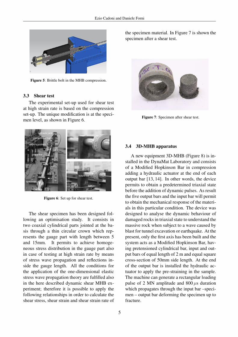
PFRC the used set-up (Figure 3) is a compres-sion version of the MHB and based on the sameloading principle used for tension test [11, 12].The input (4) and output (5) bars are in alu-minium and had a diameter of 30mm and alength of 3m. The pretensioned bar (2) is inhigh strength steel. Detailed information on thefunctioning can be found in [11]. Differentlyfrom tension version in this MHB the blockingsystem (3) is a physical block between the pre-tensioned and the input bar (see Figure 4). Thesystem is released by rupturing a bolt near thehydraulic actuator (1) as depicted in Figure 5.
Figure 3: Set up for compression test.
Figure 4: Blocking system in the MHB compression.
4
Ezio Cadoni and Daniele Forni
Figure 5: Brittle bolt in the MHB compression.
3.3 Shear testThe experimental set-up used for shear test
at high strain rate is based on the compressionset-up. The unique modification is at the speci-men level, as shown in Figure 6.
Figure 6: Set up for shear test.
The shear specimen has been designed fol-lowing an optimisation study. It consists intwo coaxial cylindrical parts jointed at the ba-sis through a thin circular crown which rep-resents the gauge part with length between 5and 15mm. It permits to achieve homoge-neous stress distribution in the gauge part alsoin case of testing at high strain rate by meansof stress wave propagation and reflections in-side the gauge length. All the conditions forthe application of the one-dimensional elasticstress wave propagation theory are fulfilled alsoin the here described dynamic shear MHB ex-periment; therefore it is possible to apply thefollowing relationships in order to calculate theshear stress, shear strain and shear strain rate of
the specimen material. In Figure 7 is shown thespecimen after a shear test.
Figure 7: Specimen after shear test.
3.4 3D-MHB apparatus
A new equipment 3D-MHB (Figure 8) is in-stalled in the DynaMat Laboratory and consistsof a Modified Hopkinson Bar in compressionadding a hydraulic actuator at the end of eachoutput bar [13, 14]. In other words, the devicepermits to obtain a predetermined triaxial statebefore the addition of dynamic pulses. As resultthe five output bars and the input bar will permitto obtain the mechanical response of the materi-als in this particular condition. The device wasdesigned to analyse the dynamic behaviour ofdamaged rocks in triaxial state to understand themassive rock when subject to a wave caused byblast for tunnel excavation or earthquake. At thepresent, only the first axis has been built and thesystem acts as a Modified Hopkinson Bar, hav-ing pretensioned cylindrical bar, input and out-put bars of equal length of 2 m and equal squarecross-section of 50mm side length. At the endof the output bar is installed the hydraulic ac-tuator to apply the pre-straining in the sample.The machine can generate a rectangular loadingpulse of 2 MN amplitude and 800µs durationwhich propagates through the input bar –speci-men – output bar deforming the specimen up tofracture.
5
Ezio Cadoni and Daniele Forni
Figure 8: 3D-MHB set-up.
In Figure 9 is shown the scheme of the uni-axial version of the 3D-MHB. It consists ofa pretensioned bar (cylindrical bar: ∅=56.5,L=1750mm)), input and output bars (withsquare cross-section: 50mm side; 2200 and2100mm in length, respectively). The totallength of the 3D-MHB apparatus along the im-pact axis is of 7.82m. The length becomes8.80m when the bumper system is installed. Allbars are made of thermally aged maraging steel.
Figure 9: 3D-MHB, uniaxial set-up.
4 ResultsFor the sake of brevity only some results
are presented (other results can be found in[1, 12–14]). In particular the results of directtension results of UHPFRC with 5% fibre con-tent are presented with the intention to highlightthe effects of the fibre reinforcement as wellas the fibre orientation and distribution. Be-ing UHPFRC mouldable material in fresh con-dition, its rheology has a capital role in the fi-bres’ distribution and orientation because theyare governed by the casting flow.
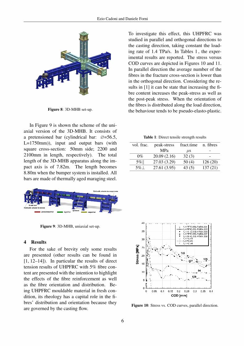
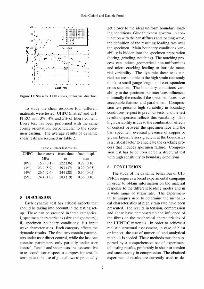
To investigate this effect, this UHPFRC wasstudied in parallel and orthogonal directions tothe casting direction, taking constant the load-ing rate of 1.4 TPa/s. In Tables 1 , the exper-imental results are reported. The stress versusCOD curves are depicted in Figures 10 and 11.In parallel direction the average number of thefibres in the fracture cross-section is lower thanin the orthogonal direction. Considering the re-sults in [1] it can be state that increasing the fi-bre content increases the peak-stress as well asthe post-peak stress. When the orientation ofthe fibres is distributed along the load direction,the behaviour tends to be pseudo-elasto-plastic.
Table 1: Direct tensile strength results
vol. frac. peak-stress fract.time n. fibresMPa µs -
0% 20.09 (2.16) 32 (3) -5%‖ 27.03 (3.29) 50 (4) 126 (20)5%⊥ 27.61 (3.95) 43 (5) 137 (21)
Figure 10: Stress vs. COD curves, parallel direction.
6
Ezio Cadoni and Daniele Forni
Figure 11: Stress vs. COD curves, orthogonal direction.
To study the shear response four differentmaterials were tested: UHPC (matrix) and UH-PFRC with 3%, 4% and 5% of fibers content.Every test has been performed with the samecoring orientation, perpendicular to the speci-men casting. The average results of dynamicshear tests are resumed in Table 2.
Table 2: Shear test results
UHPC shear stress fract. time fract. displ.MPa µs mm
(0%) 15.9 (3.1) 222 (36) 0.27 (0.10)(3%) 23.4 (5.9) 193 (37) 0.29 (0.05)(4%) 26.6 (2.6) 244 (28) 0.34 (0.05)(5%) 24.4 (1.0) 283 (19) 0.36 (0.10)
5 DISCUSSIONEach dynamic test has critical aspects that
should be taking into account in the testing set-up. These can be grouped in three categories:i) specimen characteristics (size and geometry);ii) specimen boundary conditions; iii) inputwave characteristics. Each category affects thedynamic results. The first two contain parame-ters under user direct control, while the last onecontains parameters only partially under usercontrol. Tensile and shear tests are less sensitiveto test conditions respect to compression test. Intension test the use of glue allows to practically
get closer to the ideal uniform boundary load-ing conditions. Glue thickness governs, in con-junction with the bar stiffness and loading wave,the definition of the resulting loading rate overthe specimen. Main boundary conditions vari-ability is hidden into the specimen preparation(coring, grinding, notching). The notching pro-cess can induce geometrical non-uniformitiesand micro cracking leading to intrinsic mate-rial variability. The dynamic shear tests car-ried out are suitable to the high strain rate studythank to small gauge length and correspondentcross-section. The boundary conditions vari-ability in the specimen-bar interfaces influencesminimally the results if the specimen faces haveacceptable flatness and parallelism. Compres-sion test presents high variability in boundaryconditions respect to previous tests, and the testresults dispersion reflects this variability. Thishigh variability is due to the combination effectsof contact between the specimen face and thebar, specimen, eventual presence of copper orgrease layers. Stress gradient at the boundariesis a critical factor to enucleate the cracking pro-cess that induces specimen failure. Compres-sion test has to be considered a structural testwith high sensitivity to boundary conditions.
6 CONCLUSIONThe study of the dynamic behaviour of UH-
PFRCs requires a broad experimental campaignin order to obtain information on the materialresponse to the different loading modes and ina wide range of strain rate. The experimen-tal techniques used to determine the mechani-cal characteristics at high strain rate have beenpresented. The results in tension, compressionand shear have demonstrated the influence ofthe fibres on the mechanical characteristics ofthe UHPFRC materials. In order to achieve arealistic structural assessment, in case of blastor impact, the use of numerical and analyticalmethods is needed. These methods must be sup-ported by a comprehensive set of experimen-tal testing results, preferably in shear or tensionand successively in compression. The obtainedexperimental results are currently used to de-
7

Ezio Cadoni and Daniele Forni
velop material failure criteria for structural re-liability assessment of infrastructure elementsagainst the effects of IEDs.
7 ACKNOWLEDGMENTSThis work has been supported by
armasuisse-Science and Technology of theSwiss Federal Department of Defence, CivilProtection and Sport.
REFERENCES[1] Cadoni, E., and Forni, D. 2016. Experi-
mental analysis of the UHPFRCs behav-ior under tension at high stress rate. Eur.Phys. J. Special Topics 225(2):253-264.
[2] Luccioni, B., Isla, F., Forni, D. andCadoni, E. 2018. Modelling UHPFRCtension behavior under high strain rates.Cement and Concrete Composites 91:209-220.
[3] Albertini, C., Cadoni, E. and Labibes, K.1997. Impact fracture process and me-chanical properties of plain concrete bymeans of an Hopkinson bar bundle. Jour-nal De Physique. IV 7(3): C3-915-920.
[4] Cadoni, E., Solomos, G., and Albertini, C.2006. Analysis of the concrete behaviourin tension at high strain-rate by a mod-ified Hopkinson bar in support of im-pact resistant structural design.Journal DePhysique. IV 134:647-652.
[5] Cadoni, E., Labibes, K., Berra, M., Gian-grasso, M. and Albertini, C. 2001. Influ-ence of aggregate size on strain-rate ten-sile behavior of concrete. ACI MaterialsJournal 98:220-223.
[6] Fenu, L., Forni, D. and Cadoni E. 2016.Dynamic behaviour of cement mortars re-inforced with glass and basalt fibres. Com-posites Part B: Engineering 92:142-150.
[7] Coppola, L., Cadoni, E., Forni, D. andBuoso, A. 2011. Mechanical characteriza-tion of cement composites reinforced with
fiberglass, carbon nanotubes or glass rein-forced plastic (GRP) at high strain rates.Applied Mechanics and Materials 82:190-195.
[8] Coppola, L., Coffetti, D., Crotti, E.,Forni, D. and Cadoni, E. 2018. Fiber re-inforced mortars based on free Portland-CSA binders under high stress rate. EPJWeb Conf. 183:04013.
[9] Caverzan, A., Cadoni, E. and di Prisco,M. 2012. Tensile behaviour of high perfor-mance fibre-reinforced cementitious com-posites at high strain rates. Int. J. ImpactEng. 45:28-38.
[10] Cadoni, E., 2010, Dynamic Characteriza-tion of Orthogneiss Rock Subjected to In-termediate and High Strain Rate in Ten-sion. Rock Mechanics and Rock Engineer-ing. 43:667-676.
[11] Cadoni, E., Solomos, G. and Albertini, C.2009, Mechanical characterisation of con-crete in tension and compression at highstrain rate using a modified Hopkinsonbar. Mag. Concrete Res. 61:221-230.
[12] Bragov, A., Konstantinov, A., Lomunov,A., Forni, D., Riganti, G. and Cadoni,E. 2015. High strain rate response ofUHP(FR)C in compression. EPJ Web ofConferences 94:01020.
[13] Cadoni, E., Dotta, M., Forni, D., Riganti,G. and Albertini, C. 2015. First applica-tion of the 3D-MHB on dynamic compres-sive behavior of UHPC. EPJ Web of Con-ferences 94:01031.
[14] Cadoni, E., Dotta, M. and Forni, D. 2018.Behaviour of UHPFRCs in compressionunder high stress-rates. EPJ Web Conf.183:02005.
[15] Caverzan, A., di Prisco, M. and Cadoni,E. 2015. Dynamic behaviour of HPFRCC:The influence of fibres dispersion, EPJWeb of Conferences 94:01064.
8