Embed Size (px)
Citation preview

Fracture Mechanics of Concrete and Concrete Structures -Assessment, Durability, Monitoring and Retrofitting of Concrete Structures- B. H. Oh, et al. (eds)
ⓒ 2010 Korea Concrete Institute, Seoul, ISBN 978-89-5708-181-5
A study on re-deterioration of surface-coated sluice structures due to frost damage
I. Naitoh & F. Taguchi Civil Engineering Research Institute, Sapporo, Japan
ABSTRACT: The purpose of this study is to present an appropriate application method for surface coating repair to prevent the early re-deterioration of surface-coated concrete structures. External Visual Inspection, Ultrasonic Propagation Velocity Measurement, Adhesive Strength Test Method and other investigations were conducted for sluice structures in cold, snowy regions to clarify the nature of frost deterioration depending on differences in such environments and the causes of re-deterioration. The results revealed that the degree of concrete deterioration was higher in sections that were exposed to a direct water supply, and that it varied in line with temperature and other regional conditions. A major cause of early re-deterioration was the presence of deteriorated parts remaining on Surface coating material or patching material, which led to the progress of deterioration inside the concrete due to freeze-thaw action. It was therefore found that the durability of concrete structures repaired using the surface coating method in cold, snowy regions depended greatly on pre-repair surface preparation.
1 INTRODUCTION
Concrete river structures in cold, snowy regions are exposed to severe environments and constantly af-fected by frost damage. While surface coating re-pair to block moisture from the outside is considered effective as a measure to repair concrete deteriorated by frost damage, early re-deterioration after coating has been observed in some cases. This is due to a lack of knowledge regarding the durability of exist-ing repair methods in cold, snowy environments and a lack of manuals outlining techniques for precise assessment of deterioration status and identification of areas of concrete for repair. A sluice is a type of concrete river structure consisting of an underdrain-age channel and a facility to open and close it. Its main roles include drainage of water from inside a levee to the river and intake of water from the river. It also prevents water from flowing into residential and farming areas within the levee by closing the channel at times of flooding. In Hokkaido, which is a cold, snowy region, numerous sluice structures have been built as part of river improvements on riv-ers under the direct control of the national govern-ment since around 1965. Approximately 1,500 such structures currently exist, and there is concern about a dramatic increase in repair and reconstruction ex-penses in the future due to their deterioration and ag-ing with the passage of time (Naitoh et al, 2009). Since public works spending tends to be reduced yearly, the importance of life prolongation by repair has now been revalued, and it is necessary to reduce life-cycle costs through more efficient and effective maintenance/management methods.
Accordingly, degrees of frost deterioration de-pending on differences in the conditions of cold, snowy environments were identified, and field in-vestigations of re-deteriorated surface-coated sluice concrete were conducted in this study to enable es-timation of the causes of re-deterioration and exam-ine deterioration diagnosis methods. The ultimate aim was to present an appropriate repair method and an effective inspection method as measures against frost-related deterioration of sluice concrete.
2 STUDY METHODS
Meteorological investigation and External Visual In-spection of sluice structures were conducted to assess structural deterioration due to frost damage in different environments. To examine re-deteriorated surface-coated concrete, Ultrasonic Propagation Velocity Measurement (Uomoto et al. 1990), Adhesive Strength Test Method and Visual observation of internal status were performed. The effectiveness of the deteriora-tion diagnosis method using ultrasonic propagation ve-locity measurement was also examined to improve the efficiency of investigations and to avoid a decline in the coating effect of surface-coated concrete and the infiltration of detrimental factors as much as possible.
The study is outlined in detail below. 2.1 Study of frost deterioration in sluice structures
under different environments
As shown in Figure 1, the study was conducted on the Teshio River in the Kamikawa area and the Mu-kawa and Saru rivers in the Hidaka area, which are

two typical regions of Hokkaido with differing cold, snowy environments. Table 1 shows the number of sluice structures involved in the study.
Figure 1. Locational map of the study sites.
Table 1. No. of sluices studied.
Years Teshio Mukawa Saru Total
1950s 0 0 0 0
1960s 18 6 6 30
1970s 17 13 4 34
1980s 17 5 4 26
1990s 7 4 0 11
2000s 6 5 9 20
Total 65 33 23 121
2.1.1 Meteorological investigation In the meteorological investigation, AMeDAS (Automated Meteorological Data Acquisition System by Japan Meteorological Agency) data from between October 1998 and May 2008 (Japan Meteorological Agency, 1998.October-2008.May) were used to find the annual lowest temperature, maximum snow depth, number of freeze-thaw days and number of freezing days in each area in winter (between October and May). The annual lowest temperature and maximum snow depth are the average values for this ten-year period, freeze-thaw days are those on which the daily highest temperature was 0°C or higher and the lowest temperature was -1°C or lower, and freezing days are those on which the daily highest temperature was -1°C or lower (Hama et al, 1999).
2.1.2 External visual inspection Photo 1 shows the sluice parts examined (i.e., the control platform, gatepost and retaining wall). Two parts of the retaining wall (top and underwater) were examined. The degree of frost deterioration in sluice concrete was evaluated using an appearance rating method as shown in Table 2. The appearance
of scaling deterioration was rated through external visual inspection for macroscopic evaluation in accordance with the ASTM C 672 (ASTM International, 2004) visual inspection method for laboratory testing. The highest rating for each part was adopted as that part’s overall rating. Photo 1. Sluice parts examined.
Table 2. Visual rating of surface scaling.
2.2 Study of re-deteriorated sluices
The sluice structure for which the study on re-deterioration was conducted was constructed in 1961 in Shibetsu City in the Kamikawa region. It was repaired in 2003, 42 years after its construction, using a combination of acrylic resin Patching material and Surface coating material, but cracking was observed 18 months after the repair as shown in Photo 2.
Proceedings of FraMCoS-7, May 23-28, 2010
hThD ∇−= ),(J (1)
The proportionality coefficient D(h,T) is called moisture permeability and it is a nonlinear function of the relative humidity h and temperature T (Bažant & Najjar 1972). The moisture mass balance requires that the variation in time of the water mass per unit volume of concrete (water content w) be equal to the divergence of the moisture flux J
J•∇=∂
∂−
t
w (2)
The water content w can be expressed as the sum
of the evaporable water we (capillary water, water vapor, and adsorbed water) and the non-evaporable (chemically bound) water wn (Mills 1966, Pantazopoulo & Mills 1995). It is reasonable to assume that the evaporable water is a function of relative humidity, h, degree of hydration, αc, and degree of silica fume reaction, αs, i.e. we=we(h,αc,αs) = age-dependent sorption/desorption isotherm (Norling Mjonell 1997). Under this assumption and by substituting Equation 1 into Equation 2 one obtains
nscw
s
ew
c
ew
hh
Dt
h
h
ew
&&& ++∂
∂
∂
∂
=∇•∇+∂
∂
∂
∂
− αα
αα
)(
(3)
where ∂we/∂h is the slope of the sorption/desorption isotherm (also called moisture capacity). The governing equation (Equation 3) must be completed by appropriate boundary and initial conditions.
The relation between the amount of evaporable water and relative humidity is called ‘‘adsorption isotherm” if measured with increasing relativity humidity and ‘‘desorption isotherm” in the opposite case. Neglecting their difference (Xi et al. 1994), in the following, ‘‘sorption isotherm” will be used with reference to both sorption and desorption conditions. By the way, if the hysteresis of the moisture isotherm would be taken into account, two different relation, evaporable water vs relative humidity, must be used according to the sign of the variation of the relativity humidity. The shape of the sorption isotherm for HPC is influenced by many parameters, especially those that influence extent and rate of the chemical reactions and, in turn, determine pore structure and pore size distribution (water-to-cement ratio, cement chemical composition, SF content, curing time and method, temperature, mix additives, etc.). In the literature various formulations can be found to describe the sorption isotherm of normal concrete (Xi et al. 1994). However, in the present paper the semi-empirical expression proposed by Norling Mjornell (1997) is adopted because it
explicitly accounts for the evolution of hydration reaction and SF content. This sorption isotherm reads
( ) ( )( )
( ) ( )⎥⎥
⎦
⎤
⎢⎢
⎣
⎡
⎥⎥⎥
⎦
⎤
⎢⎢⎢
⎣
⎡
−
−∞
+
−∞
−=
1110
,1
110
11,
1,,
hcc
ge
scK
hcc
ge
scG
sch
ew
αα
αα
αα
αααα
(4)
where the first term (gel isotherm) represents the physically bound (adsorbed) water and the second term (capillary isotherm) represents the capillary water. This expression is valid only for low content of SF. The coefficient G1 represents the amount of water per unit volume held in the gel pores at 100% relative humidity, and it can be expressed (Norling Mjornell 1997) as
( ) ss
s
vgkc
c
c
vgk
scG αααα +=,1
(5)
where k
cvg and k
svg are material parameters. From the
maximum amount of water per unit volume that can fill all pores (both capillary pores and gel pores), one can calculate K1 as one obtains
( )1
110
110
11
22.0188.00
,1
−⎟⎠
⎞⎜⎝
⎛−∞
⎥⎥⎥
⎦
⎤
⎢⎢⎢
⎣
⎡⎟⎠
⎞⎜⎝
⎛−∞
−−+−
=
hcc
ge
hcc
geGs
ssc
w
scK
αα
αα
αα
αα
(6)
The material parameters k
cvg and k
svg and g1 can
be calibrated by fitting experimental data relevant to free (evaporable) water content in concrete at various ages (Di Luzio & Cusatis 2009b).
2.2 Temperature evolution
Note that, at early age, since the chemical reactions associated with cement hydration and SF reaction are exothermic, the temperature field is not uniform for non-adiabatic systems even if the environmental temperature is constant. Heat conduction can be described in concrete, at least for temperature not exceeding 100°C (Bažant & Kaplan 1996), by Fourier’s law, which reads
T∇−= λq (7)
where q is the heat flux, T is the absolute temperature, and λ is the heat conductivity; in this
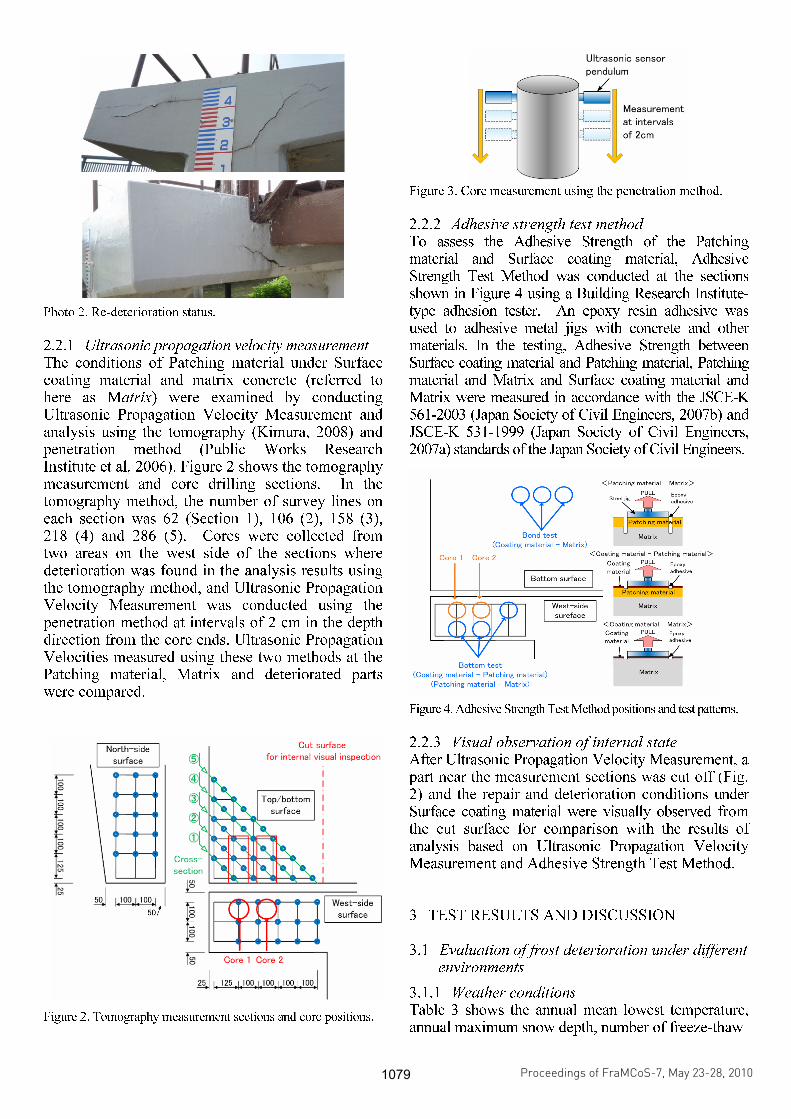
Photo 2. Re-deterioration status.
2.2.1 Ultrasonic propagation velocity measurement The conditions of Patching material under Surface coating material and matrix concrete (referred to here as Matrix) were examined by conducting Ultrasonic Propagation Velocity Measurement and analysis using the tomography (Kimura, 2008) and penetration method (Public Works Research Institute et al, 2006). Figure 2 shows the tomography measurement and core drilling sections. In the tomography method, the number of survey lines on each section was 62 (Section 1), 106 (2), 158 (3), 218 (4) and 286 (5). Cores were collected from two areas on the west side of the sections where deterioration was found in the analysis results using the tomography method, and Ultrasonic Propagation Velocity Measurement was conducted using the penetration method at intervals of 2 cm in the depth direction from the core ends. Ultrasonic Propagation Velocities measured using these two methods at the Patching material, Matrix and deteriorated parts were compared. Figure 2. Tomography measurement sections and core positions.
Figure 3. Core measurement using the penetration method.
2.2.2 Adhesive strength test method To assess the Adhesive Strength of the Patching material and Surface coating material, Adhesive Strength Test Method was conducted at the sections shown in Figure 4 using a Building Research Institute-type adhesion tester. An epoxy resin adhesive was used to adhesive metal jigs with concrete and other materials. In the testing, Adhesive Strength between Surface coating material and Patching material, Patching material and Matrix and Surface coating material and Matrix were measured in accordance with the JSCE-K 561-2003 (Japan Society of Civil Engineers, 2007b) and JSCE-K 531-1999 (Japan Society of Civil Engineers, 2007a) standards of the Japan Society of Civil Engineers.
Figure 4. Adhesive Strength Test Method positions and test patterns.
2.2.3 Visual observation of internal state After Ultrasonic Propagation Velocity Measurement, a part near the measurement sections was cut off (Fig. 2) and the repair and deterioration conditions under Surface coating material were visually observed from the cut surface for comparison with the results of analysis based on Ultrasonic Propagation Velocity Measurement and Adhesive Strength Test Method.
3 TEST RESULTS AND DISCUSSION
3.1 Evaluation of frost deterioration under different environments
3.1.1 Weather conditions Table 3 shows the annual mean lowest temperature, annual maximum snow depth, number of freeze-thaw
Proceedings of FraMCoS-7, May 23-28, 2010
hThD ∇−= ),(J (1)
The proportionality coefficient D(h,T) is called moisture permeability and it is a nonlinear function of the relative humidity h and temperature T (Bažant & Najjar 1972). The moisture mass balance requires that the variation in time of the water mass per unit volume of concrete (water content w) be equal to the divergence of the moisture flux J
J•∇=∂
∂−
t
w (2)
The water content w can be expressed as the sum
of the evaporable water we (capillary water, water vapor, and adsorbed water) and the non-evaporable (chemically bound) water wn (Mills 1966, Pantazopoulo & Mills 1995). It is reasonable to assume that the evaporable water is a function of relative humidity, h, degree of hydration, αc, and degree of silica fume reaction, αs, i.e. we=we(h,αc,αs) = age-dependent sorption/desorption isotherm (Norling Mjonell 1997). Under this assumption and by substituting Equation 1 into Equation 2 one obtains
nscw
s
ew
c
ew
hh
Dt
h
h
ew
&&& ++∂
∂
∂
∂
=∇•∇+∂
∂
∂
∂
− αα
αα
)(
(3)
where ∂we/∂h is the slope of the sorption/desorption isotherm (also called moisture capacity). The governing equation (Equation 3) must be completed by appropriate boundary and initial conditions.
The relation between the amount of evaporable water and relative humidity is called ‘‘adsorption isotherm” if measured with increasing relativity humidity and ‘‘desorption isotherm” in the opposite case. Neglecting their difference (Xi et al. 1994), in the following, ‘‘sorption isotherm” will be used with reference to both sorption and desorption conditions. By the way, if the hysteresis of the moisture isotherm would be taken into account, two different relation, evaporable water vs relative humidity, must be used according to the sign of the variation of the relativity humidity. The shape of the sorption isotherm for HPC is influenced by many parameters, especially those that influence extent and rate of the chemical reactions and, in turn, determine pore structure and pore size distribution (water-to-cement ratio, cement chemical composition, SF content, curing time and method, temperature, mix additives, etc.). In the literature various formulations can be found to describe the sorption isotherm of normal concrete (Xi et al. 1994). However, in the present paper the semi-empirical expression proposed by Norling Mjornell (1997) is adopted because it
explicitly accounts for the evolution of hydration reaction and SF content. This sorption isotherm reads
( ) ( )( )
( ) ( )⎥⎥
⎦
⎤
⎢⎢
⎣
⎡
⎥⎥⎥
⎦
⎤
⎢⎢⎢
⎣
⎡
−
−∞
+
−∞
−=
1110
,1
110
11,
1,,
hcc
ge
scK
hcc
ge
scG
sch
ew
αα
αα
αα
αααα
(4)
where the first term (gel isotherm) represents the physically bound (adsorbed) water and the second term (capillary isotherm) represents the capillary water. This expression is valid only for low content of SF. The coefficient G1 represents the amount of water per unit volume held in the gel pores at 100% relative humidity, and it can be expressed (Norling Mjornell 1997) as
( ) ss
s
vgkc
c
c
vgk
scG αααα +=,1
(5)
where k
cvg and k
svg are material parameters. From the
maximum amount of water per unit volume that can fill all pores (both capillary pores and gel pores), one can calculate K1 as one obtains
( )1
110
110
11
22.0188.00
,1
−⎟⎠
⎞⎜⎝
⎛−∞
⎥⎥⎥
⎦
⎤
⎢⎢⎢
⎣
⎡⎟⎠
⎞⎜⎝
⎛−∞
−−+−
=
hcc
ge
hcc
geGs
ssc
w
scK
αα
αα
αα
αα
(6)
The material parameters k
cvg and k
svg and g1 can
be calibrated by fitting experimental data relevant to free (evaporable) water content in concrete at various ages (Di Luzio & Cusatis 2009b).
2.2 Temperature evolution
Note that, at early age, since the chemical reactions associated with cement hydration and SF reaction are exothermic, the temperature field is not uniform for non-adiabatic systems even if the environmental temperature is constant. Heat conduction can be described in concrete, at least for temperature not exceeding 100°C (Bažant & Kaplan 1996), by Fourier’s law, which reads
T∇−= λq (7)
where q is the heat flux, T is the absolute temperature, and λ is the heat conductivity; in this

days and number of freezing days in each region.
A comparison of weather conditions in the two
regions indicates that the Kamikawa area has a
severe cold, snowy environment, as the annual mean
lowest temperature is lower and the annual maximum
snow depth is greater. While the number of freezing
days is higher in Kamikawa, the number of freeze-
thaw days is higher in Hidaka. It can be seen from
these results that the influences on sluice concrete in
these two areas are different in winter.
3.1.2 Appearance rating Figure 5 shows the results of appearance rating by section based on external visual inspection, and Figure 6 shows the results of control platform appearance rating by the number of in-service years. By part, the control platform rating was generally the highest, followed by the underwater part of the retaining wall, the top part of the retaining wall and the gatepost. Control platform frost deterioration was especially severe, with a rating of up to 5 in some cases. Since control platforms have a shape on which snow is likely to accumulate and their structure is relatively thin, they are more susceptible to the influence of freeze-thaw action caused by the retention of snowmelt and other factors. Conversely, gateposts are not susceptible to freeze-thaw action as they stand behind control platforms and are minimally exposed to snow accumulation and sunlight. It was found from this that parts directly affected by water supply are also affected significantly by freeze-thaw action, and that the degree of deterioration found in them increases. Table 3. Weather conditions of different areas.
Figure 5. Appearance rating of river sluices by part.
By region, the ratio of parts rated three or higher was generally greater on the Mukawa and Saru rivers than on the Teshio River, although no ratings of four or higher were observed except for control platforms. Conversely, while some gateposts and retaining walls were rated four on the Teshio River, the ratio of lower ratings was generally higher compared with those of the Mukawa and Saru rivers. Looking at the number of in-service years, ratings tended to be higher for structures that had been used for 20 years or more on the Teshio River and for 30 years or more on the Mukawa and Saru rivers. It can therefore be said that frost deterioration progressed faster and its degree tended to be greater in the Kamikawa region, while the phenomenon tended to
Figure 6. Appearance ratio of each sluice control platform by the number of in-service years.
Region
Annual low-
est tempera-
ture
(°C)
Annual max.
snow depth
(cm)
No. of freez-
ing days
No. of
freeze-thaw
days
Otoineppu -29.0 201.0 93.6 61.7
Bifuka -29.0 147.3 91.4 64.1
Nayoro -27.5 114.4 92.8 66.4
Shimokawa -30.0 131.0 93.6 73.2
Shibetsu -28.5 119.3 94.8 58.7
Kamikawa
Asahi -24.1 No
data 95.3 63.2
Mukawa -21.9 37.7 56.8 91.5
Hobetsu -25.3 54.6 60.7 102.9 Hidaka
Hidaka Monbetsu
-17.7 20.2 46.9 91.0
Proceedings of FraMCoS-7, May 23-28, 2010
hThD ∇−= ),(J (1)
The proportionality coefficient D(h,T) is called moisture permeability and it is a nonlinear function of the relative humidity h and temperature T (Bažant & Najjar 1972). The moisture mass balance requires that the variation in time of the water mass per unit volume of concrete (water content w) be equal to the divergence of the moisture flux J
J•∇=∂
∂−
t
w (2)
The water content w can be expressed as the sum
of the evaporable water we (capillary water, water vapor, and adsorbed water) and the non-evaporable (chemically bound) water wn (Mills 1966, Pantazopoulo & Mills 1995). It is reasonable to assume that the evaporable water is a function of relative humidity, h, degree of hydration, αc, and degree of silica fume reaction, αs, i.e. we=we(h,αc,αs) = age-dependent sorption/desorption isotherm (Norling Mjonell 1997). Under this assumption and by substituting Equation 1 into Equation 2 one obtains
nscw
s
ew
c
ew
hh
Dt
h
h
ew
&&& ++∂
∂
∂
∂
=∇•∇+∂
∂
∂
∂
− αα
αα
)(
(3)
where ∂we/∂h is the slope of the sorption/desorption isotherm (also called moisture capacity). The governing equation (Equation 3) must be completed by appropriate boundary and initial conditions.
The relation between the amount of evaporable water and relative humidity is called ‘‘adsorption isotherm” if measured with increasing relativity humidity and ‘‘desorption isotherm” in the opposite case. Neglecting their difference (Xi et al. 1994), in the following, ‘‘sorption isotherm” will be used with reference to both sorption and desorption conditions. By the way, if the hysteresis of the moisture isotherm would be taken into account, two different relation, evaporable water vs relative humidity, must be used according to the sign of the variation of the relativity humidity. The shape of the sorption isotherm for HPC is influenced by many parameters, especially those that influence extent and rate of the chemical reactions and, in turn, determine pore structure and pore size distribution (water-to-cement ratio, cement chemical composition, SF content, curing time and method, temperature, mix additives, etc.). In the literature various formulations can be found to describe the sorption isotherm of normal concrete (Xi et al. 1994). However, in the present paper the semi-empirical expression proposed by Norling Mjornell (1997) is adopted because it
explicitly accounts for the evolution of hydration reaction and SF content. This sorption isotherm reads
( ) ( )( )
( ) ( )⎥⎥
⎦
⎤
⎢⎢
⎣
⎡
⎥⎥⎥
⎦
⎤
⎢⎢⎢
⎣
⎡
−
−∞
+
−∞
−=
1110
,1
110
11,
1,,
hcc
ge
scK
hcc
ge
scG
sch
ew
αα
αα
αα
αααα
(4)
where the first term (gel isotherm) represents the physically bound (adsorbed) water and the second term (capillary isotherm) represents the capillary water. This expression is valid only for low content of SF. The coefficient G1 represents the amount of water per unit volume held in the gel pores at 100% relative humidity, and it can be expressed (Norling Mjornell 1997) as
( ) ss
s
vgkc
c
c
vgk
scG αααα +=,1
(5)
where k
cvg and k
svg are material parameters. From the
maximum amount of water per unit volume that can fill all pores (both capillary pores and gel pores), one can calculate K1 as one obtains
( )1
110
110
11
22.0188.00
,1
−⎟⎠
⎞⎜⎝
⎛−∞
⎥⎥⎥
⎦
⎤
⎢⎢⎢
⎣
⎡⎟⎠
⎞⎜⎝
⎛−∞
−−+−
=
hcc
ge
hcc
geGs
ssc
w
scK
αα
αα
αα
αα
(6)
The material parameters k
cvg and k
svg and g1 can
be calibrated by fitting experimental data relevant to free (evaporable) water content in concrete at various ages (Di Luzio & Cusatis 2009b).
2.2 Temperature evolution
Note that, at early age, since the chemical reactions associated with cement hydration and SF reaction are exothermic, the temperature field is not uniform for non-adiabatic systems even if the environmental temperature is constant. Heat conduction can be described in concrete, at least for temperature not exceeding 100°C (Bažant & Kaplan 1996), by Fourier’s law, which reads
T∇−= λq (7)
where q is the heat flux, T is the absolute temperature, and λ is the heat conductivity; in this

occur regardless of part types in the Hidaka region, although the progress of deterioration there was slower and no significant deterioration was observed. Figure 7 shows the repair and re-deterioration rates in the two regions. While the repair rate was around 20% in both, re-deterioration occurred in more than half of the sluices after repair. It also occurred in all surface-coated sluices in both regions. Figure 7. Repair and re-deterioration rates.
These results indicate problems regarding the du-
rability of existing repairs in cold, snowy environ-ments.
The above results reveal that appropriate meas-ures against frost damage depending on differing re-gional environments must be taken to prevent re-deterioration, since the degree of frost deterioration in sluice concrete varies with differences in cold, snowy environments and the durability of existing repair methods is unclear.
3.2 Estimation of the causes of re-deterioration, and deterioration diagnosis
3.2.1 Ultrasonic Propagation Velocity Measurement Figure 8 shows Ultrasonic Propagation Velocity distribution in Sections 1 to 5 as found using the tomography method. Since the velocity was generally lower on the outside than on the inside and the distribution is round at the corners of each cross-section, it was presumed that Patching was conducted for defective corners. As such defects represent a type of deterioration peculiar to frost damage, it can be assumed that frost deterioration had occurred in Matrix
Figure 8. Velocity distribution on each cross-section as found using the tomography method.
before repair. It can also be seen that the defect on the west side was slightly deeper and larger in area than that on the north side. This was probably be-cause of the greater influence of freeze-thaw action due to the more abundant sunlight on the west side. In addition, the velocity became very low in a V-shaped part on the topside of Section (4), indicating an internal defect in the vicinity. However, there were generally no clear differences in velocity between the repair material and the deteriorated parts of the matrix.
Figure 9 shows the velocity results for collected cores as assessed using the penetration method. Patching material thickness was around 10 cm and Patching material velocity was around 3,500 m/sec for both cores 1 and 2. While the velocity of con-crete is generally 3,500 m/sec or higher, the value was a little higher than 2,000/sec in some parts of Matrixes of both cores, indicating partial deteriora-tion. Since these sections are positioned similarly to the deteriorated part on the topside of Section (4)
Figure 9. Ultrasonic Propagation Velocity of cores as found us-ing the penetration method.
Proceedings of FraMCoS-7, May 23-28, 2010
hThD ∇−= ),(J (1)
The proportionality coefficient D(h,T) is called moisture permeability and it is a nonlinear function of the relative humidity h and temperature T (Bažant & Najjar 1972). The moisture mass balance requires that the variation in time of the water mass per unit volume of concrete (water content w) be equal to the divergence of the moisture flux J
J•∇=∂
∂−
t
w (2)
The water content w can be expressed as the sum
of the evaporable water we (capillary water, water vapor, and adsorbed water) and the non-evaporable (chemically bound) water wn (Mills 1966, Pantazopoulo & Mills 1995). It is reasonable to assume that the evaporable water is a function of relative humidity, h, degree of hydration, αc, and degree of silica fume reaction, αs, i.e. we=we(h,αc,αs) = age-dependent sorption/desorption isotherm (Norling Mjonell 1997). Under this assumption and by substituting Equation 1 into Equation 2 one obtains
nscw
s
ew
c
ew
hh
Dt
h
h
ew
&&& ++∂
∂
∂
∂
=∇•∇+∂
∂
∂
∂
− αα
αα
)(
(3)
where ∂we/∂h is the slope of the sorption/desorption isotherm (also called moisture capacity). The governing equation (Equation 3) must be completed by appropriate boundary and initial conditions.
The relation between the amount of evaporable water and relative humidity is called ‘‘adsorption isotherm” if measured with increasing relativity humidity and ‘‘desorption isotherm” in the opposite case. Neglecting their difference (Xi et al. 1994), in the following, ‘‘sorption isotherm” will be used with reference to both sorption and desorption conditions. By the way, if the hysteresis of the moisture isotherm would be taken into account, two different relation, evaporable water vs relative humidity, must be used according to the sign of the variation of the relativity humidity. The shape of the sorption isotherm for HPC is influenced by many parameters, especially those that influence extent and rate of the chemical reactions and, in turn, determine pore structure and pore size distribution (water-to-cement ratio, cement chemical composition, SF content, curing time and method, temperature, mix additives, etc.). In the literature various formulations can be found to describe the sorption isotherm of normal concrete (Xi et al. 1994). However, in the present paper the semi-empirical expression proposed by Norling Mjornell (1997) is adopted because it
explicitly accounts for the evolution of hydration reaction and SF content. This sorption isotherm reads
( ) ( )( )
( ) ( )⎥⎥
⎦
⎤
⎢⎢
⎣
⎡
⎥⎥⎥
⎦
⎤
⎢⎢⎢
⎣
⎡
−
−∞
+
−∞
−=
1110
,1
110
11,
1,,
hcc
ge
scK
hcc
ge
scG
sch
ew
αα
αα
αα
αααα
(4)
where the first term (gel isotherm) represents the physically bound (adsorbed) water and the second term (capillary isotherm) represents the capillary water. This expression is valid only for low content of SF. The coefficient G1 represents the amount of water per unit volume held in the gel pores at 100% relative humidity, and it can be expressed (Norling Mjornell 1997) as
( ) ss
s
vgkc
c
c
vgk
scG αααα +=,1
(5)
where k
cvg and k
svg are material parameters. From the
maximum amount of water per unit volume that can fill all pores (both capillary pores and gel pores), one can calculate K1 as one obtains
( )1
110
110
11
22.0188.00
,1
−⎟⎠
⎞⎜⎝
⎛−∞
⎥⎥⎥
⎦
⎤
⎢⎢⎢
⎣
⎡⎟⎠
⎞⎜⎝
⎛−∞
−−+−
=
hcc
ge
hcc
geGs
ssc
w
scK
αα
αα
αα
αα
(6)
The material parameters k
cvg and k
svg and g1 can
be calibrated by fitting experimental data relevant to free (evaporable) water content in concrete at various ages (Di Luzio & Cusatis 2009b).
2.2 Temperature evolution
Note that, at early age, since the chemical reactions associated with cement hydration and SF reaction are exothermic, the temperature field is not uniform for non-adiabatic systems even if the environmental temperature is constant. Heat conduction can be described in concrete, at least for temperature not exceeding 100°C (Bažant & Kaplan 1996), by Fourier’s law, which reads
T∇−= λq (7)
where q is the heat flux, T is the absolute temperature, and λ is the heat conductivity; in this

where the velocity was low, it was found that the position of internal deterioration can be identified to a certain degree using the tomography method. These results indicate that the internal state and de-gree of deterioration under Surface coating material can be roughly determined by Ultrasonic Propaga-tion Velocity Measurement, and the technique’s va-lidity as a frost deterioration diagnosis method was confirmed.
3.2.2 Adhesive strength Figure 10 shows Adhesive Strength test Method results. Adhesive Strength between Surface coating material and Patching material was 1.630 N/mm
2.
The catalog standard value is 1.5 N/mm2 or larger.
Since NEXCO’s (Nippon expressway Company) quality standard (JHS-416) (NEXCO.2004) for Patching materials (known as the common reference values for Adhesive Strength in Japan) specifies Adhesive Strength between Surface coating material and Patching material as 1.0 N/mm
2 or higher and
that between Patching material and concrete as 1.5 N/mm
2 or higher, Adhesive Strength assessed in this
study can be considered sufficient. However, Adhesive Strength values between Surface coating material and Matrix and between Patching material and Matrix were very low (0.507 and 0.404 N/mm
2).
In these sections, fracturing occurred in the deteriorated Matrix but not in the adhesive surface with Matrix, as shown in Photo 3. Since external influences had been blocked until cracking in Surface coating material occurred 18 months after the repair, deterioration in sound Matrixes was unlikely at the post-repair stage. Accordingly, it was highly likely that the deteriorated parts of Matrix remained at the time of repair.
3.2.3 Internal state Photo 4 shows a cross section created by cutting part of a control platform. Cross-sectional repair using a Patching material had been conducted for the inside of the defective Matrix, and Surface coating material had been applied to the surface. This corresponded roughly with the internal state found in the above-mentioned analysis using the tomography method.
Figure 10. Adhesive Strength.
Photo 3. Fracture conditions.
Since voids were observed near the interface between Matrix and Patching material, it was also presumed that deterioration in Matrix near the interface progressed and cracking occurred in Surface coating material at the bottom. This result also supported the outcomes of Adhesive Strength Test Method. Since the repair of this sluice structure was conducted in winter, it is highly likely that removal of the deteriorated part of Matrix was incomplete in the surface preparation before the repair, and that Patching material and Surface coating material were applied while moisture from snow accretion and other sources was still present
Photo 4. Cross section of the control platform.
Proceedings of FraMCoS-7, May 23-28, 2010
hThD ∇−= ),(J (1)
The proportionality coefficient D(h,T) is called moisture permeability and it is a nonlinear function of the relative humidity h and temperature T (Bažant & Najjar 1972). The moisture mass balance requires that the variation in time of the water mass per unit volume of concrete (water content w) be equal to the divergence of the moisture flux J
J•∇=∂
∂−
t
w (2)
The water content w can be expressed as the sum
of the evaporable water we (capillary water, water vapor, and adsorbed water) and the non-evaporable (chemically bound) water wn (Mills 1966, Pantazopoulo & Mills 1995). It is reasonable to assume that the evaporable water is a function of relative humidity, h, degree of hydration, αc, and degree of silica fume reaction, αs, i.e. we=we(h,αc,αs) = age-dependent sorption/desorption isotherm (Norling Mjonell 1997). Under this assumption and by substituting Equation 1 into Equation 2 one obtains
nscw
s
ew
c
ew
hh
Dt
h
h
ew
&&& ++∂
∂
∂
∂
=∇•∇+∂
∂
∂
∂
− αα
αα
)(
(3)
where ∂we/∂h is the slope of the sorption/desorption isotherm (also called moisture capacity). The governing equation (Equation 3) must be completed by appropriate boundary and initial conditions.
The relation between the amount of evaporable water and relative humidity is called ‘‘adsorption isotherm” if measured with increasing relativity humidity and ‘‘desorption isotherm” in the opposite case. Neglecting their difference (Xi et al. 1994), in the following, ‘‘sorption isotherm” will be used with reference to both sorption and desorption conditions. By the way, if the hysteresis of the moisture isotherm would be taken into account, two different relation, evaporable water vs relative humidity, must be used according to the sign of the variation of the relativity humidity. The shape of the sorption isotherm for HPC is influenced by many parameters, especially those that influence extent and rate of the chemical reactions and, in turn, determine pore structure and pore size distribution (water-to-cement ratio, cement chemical composition, SF content, curing time and method, temperature, mix additives, etc.). In the literature various formulations can be found to describe the sorption isotherm of normal concrete (Xi et al. 1994). However, in the present paper the semi-empirical expression proposed by Norling Mjornell (1997) is adopted because it
explicitly accounts for the evolution of hydration reaction and SF content. This sorption isotherm reads
( ) ( )( )
( ) ( )⎥⎥
⎦
⎤
⎢⎢
⎣
⎡
⎥⎥⎥
⎦
⎤
⎢⎢⎢
⎣
⎡
−
−∞
+
−∞
−=
1110
,1
110
11,
1,,
hcc
ge
scK
hcc
ge
scG
sch
ew
αα
αα
αα
αααα
(4)
where the first term (gel isotherm) represents the physically bound (adsorbed) water and the second term (capillary isotherm) represents the capillary water. This expression is valid only for low content of SF. The coefficient G1 represents the amount of water per unit volume held in the gel pores at 100% relative humidity, and it can be expressed (Norling Mjornell 1997) as
( ) ss
s
vgkc
c
c
vgk
scG αααα +=,1
(5)
where k
cvg and k
svg are material parameters. From the
maximum amount of water per unit volume that can fill all pores (both capillary pores and gel pores), one can calculate K1 as one obtains
( )1
110
110
11
22.0188.00
,1
−⎟⎠
⎞⎜⎝
⎛−∞
⎥⎥⎥
⎦
⎤
⎢⎢⎢
⎣
⎡⎟⎠
⎞⎜⎝
⎛−∞
−−+−
=
hcc
ge
hcc
geGs
ssc
w
scK
αα
αα
αα
αα
(6)
The material parameters k
cvg and k
svg and g1 can
be calibrated by fitting experimental data relevant to free (evaporable) water content in concrete at various ages (Di Luzio & Cusatis 2009b).
2.2 Temperature evolution
Note that, at early age, since the chemical reactions associated with cement hydration and SF reaction are exothermic, the temperature field is not uniform for non-adiabatic systems even if the environmental temperature is constant. Heat conduction can be described in concrete, at least for temperature not exceeding 100°C (Bažant & Kaplan 1996), by Fourier’s law, which reads
T∇−= λq (7)
where q is the heat flux, T is the absolute temperature, and λ is the heat conductivity; in this

inside the voids of the remaining deteriorated part. Accordingly, it is presumed that the progress of frost damage due to moisture retention in the deteriorated part of Matrix caused early re-deterioration, and that the cracks in Surface coating material caused by such deterioration let in more water, thereby accel-erating frost deterioration.
4 CONCLUSION
The findings of this study are as follows:
(1) Since the degree of frost deterioration in sluice
concrete varies by differences in cold, snowy
environments and re-deterioration occurred in
more than half of repaired sluices, it is
necessary to take appropriate measures against
frost damage depending on regional
environments to prevent re-deterioration.
(2) Since Ultrasonic Propagation Velocity
Measurement can determine the internal state
and degree of deterioration under Surface
coating material, its validity as a method for
frost deterioration diagnosis is confirmed.
(3) Early re-deterioration of Surface-coated
concrete was presumed to be caused by the
progress of frost deterioration as a result of
insufficient removal of deteriorated parts of
Matrix at the time of repair and the
confinement of water remaining in deteriorated
parts by the surface coating material.
These results indicate the necessity of establish-
ing accurate frost damage diagnosis and appropriate repair methods depending on deterioration conditions, since the durability of surface-coated concrete in cold, snowy environments greatly affects not only material properties but also the environment at the time of repair and the need for surface preparation of concrete before repair. The authors plan further stud-ies and investigations to contribute to the extension of sluice concrete’s service life and the reduction of maintenance/management costs.
REFERENCES
ASTM International. 2004. Annual Book of ASTM Standards 2004 “Standard Test Method for Scaling Resistance of Concrete Surface Exposed to Deicing Chemicals” Vol-ume 04.02 : 353-355. West Conshohoken,PA.
Hama,Y., Matsumura, K., Tabata,M., Tomita,T. & Kameda,E . 1999 . Estimation of Frost Damage of Concrete based on Meteorological Factors : Journal of Structural and Con-struction Engineering, No. 523 : 9-16.
Japan Meteorological Agency . 1998.October -2008.May : AMeDAS data.
Japan Society of Civil Engineers. 2007a. Standard Specifica-tions for Concrete Structures – 2007 “Test Methods and Specifications”, JSCE-K 531-1999,Test method for bond strength of concrete surface coating materials,332-334.
Japan Society of Civil Engineers. 2007b. Standard Specifica-tions for Concrete Structures – 2007 “Test Methods and Specifications”, JSCE-K 561-2003,Test method of patching repair materials in concrete structures,359-364.
Kimura,Y . 2008. Estimation of Quality of Concrete Structure by Ultrasonic Tomography Method , Journal of the Gen-eral Building Research Corporation of Japan (GBRC) , Vol. 33 , No. 2 : 13-21.
Naitoh,I., Taguchi,F. Ishiya,T., Hata,H. & Deai,T.2009. Sur-vey of Frost Damage and Re-deterioration to River Sluices : Monthly Report of the Civil Engineering Research Institute of Hokkaido, No.678: 17-26.
NEXCO (Nippon expressway Company) .2004. NEXCO’s quality standards for patch repair materials ,JHS-416-2004.
Public Works Research Institute . & Japanese Society for Non-Destructive Inspection . 2006 . Guidelines on the strength measurement of newly built concrete structures by ultra-sonic testing (Doken method) (draft) .
Uomoto,T . Kato,K . Hirono,S . 1990. Non-Destructive Inspec-tion of Concrete Structures : Morikita Shuppan .
Proceedings of FraMCoS-7, May 23-28, 2010
hThD ∇−= ),(J (1)
The proportionality coefficient D(h,T) is called moisture permeability and it is a nonlinear function of the relative humidity h and temperature T (Bažant & Najjar 1972). The moisture mass balance requires that the variation in time of the water mass per unit volume of concrete (water content w) be equal to the divergence of the moisture flux J
J•∇=∂
∂−
t
w (2)
The water content w can be expressed as the sum
of the evaporable water we (capillary water, water vapor, and adsorbed water) and the non-evaporable (chemically bound) water wn (Mills 1966, Pantazopoulo & Mills 1995). It is reasonable to assume that the evaporable water is a function of relative humidity, h, degree of hydration, αc, and degree of silica fume reaction, αs, i.e. we=we(h,αc,αs) = age-dependent sorption/desorption isotherm (Norling Mjonell 1997). Under this assumption and by substituting Equation 1 into Equation 2 one obtains
nscw
s
ew
c
ew
hh
Dt
h
h
ew
&&& ++∂
∂
∂
∂
=∇•∇+∂
∂
∂
∂
− αα
αα
)(
(3)
where ∂we/∂h is the slope of the sorption/desorption isotherm (also called moisture capacity). The governing equation (Equation 3) must be completed by appropriate boundary and initial conditions.
The relation between the amount of evaporable water and relative humidity is called ‘‘adsorption isotherm” if measured with increasing relativity humidity and ‘‘desorption isotherm” in the opposite case. Neglecting their difference (Xi et al. 1994), in the following, ‘‘sorption isotherm” will be used with reference to both sorption and desorption conditions. By the way, if the hysteresis of the moisture isotherm would be taken into account, two different relation, evaporable water vs relative humidity, must be used according to the sign of the variation of the relativity humidity. The shape of the sorption isotherm for HPC is influenced by many parameters, especially those that influence extent and rate of the chemical reactions and, in turn, determine pore structure and pore size distribution (water-to-cement ratio, cement chemical composition, SF content, curing time and method, temperature, mix additives, etc.). In the literature various formulations can be found to describe the sorption isotherm of normal concrete (Xi et al. 1994). However, in the present paper the semi-empirical expression proposed by Norling Mjornell (1997) is adopted because it
explicitly accounts for the evolution of hydration reaction and SF content. This sorption isotherm reads
( ) ( )( )
( ) ( )⎥⎥
⎦
⎤
⎢⎢
⎣
⎡
⎥⎥⎥
⎦
⎤
⎢⎢⎢
⎣
⎡
−
−∞
+
−∞
−=
1110
,1
110
11,
1,,
hcc
ge
scK
hcc
ge
scG
sch
ew
αα
αα
αα
αααα
(4)
where the first term (gel isotherm) represents the physically bound (adsorbed) water and the second term (capillary isotherm) represents the capillary water. This expression is valid only for low content of SF. The coefficient G1 represents the amount of water per unit volume held in the gel pores at 100% relative humidity, and it can be expressed (Norling Mjornell 1997) as
( ) ss
s
vgkc
c
c
vgk
scG αααα +=,1
(5)
where k
cvg and k
svg are material parameters. From the
maximum amount of water per unit volume that can fill all pores (both capillary pores and gel pores), one can calculate K1 as one obtains
( )1
110
110
11
22.0188.00
,1
−⎟⎠
⎞⎜⎝
⎛−∞
⎥⎥⎥
⎦
⎤
⎢⎢⎢
⎣
⎡⎟⎠
⎞⎜⎝
⎛−∞
−−+−
=
hcc
ge
hcc
geGs
ssc
w
scK
αα
αα
αα
αα
(6)
The material parameters k
cvg and k
svg and g1 can
be calibrated by fitting experimental data relevant to free (evaporable) water content in concrete at various ages (Di Luzio & Cusatis 2009b).
2.2 Temperature evolution
Note that, at early age, since the chemical reactions associated with cement hydration and SF reaction are exothermic, the temperature field is not uniform for non-adiabatic systems even if the environmental temperature is constant. Heat conduction can be described in concrete, at least for temperature not exceeding 100°C (Bažant & Kaplan 1996), by Fourier’s law, which reads
T∇−= λq (7)
where q is the heat flux, T is the absolute temperature, and λ is the heat conductivity; in this