Embed Size (px)
Citation preview
HIGH RESOLUTION IMPULSE ANALYSING SYSTEM-HARDWARE AND
SOFTWARE IMPLEMENTATION
AHMAD TARMIMI BIN KASSIM
UNIVERSITI TEKNOLOGI MALAYSIA
HIGH RESOLUTION IMPULSE ANALYSING SYSTEM- HARDWARE AND
SOFTWARE IMPLEMENTATION
AHMAD TARMIMI BIN KASSIM
A project report submitted in partial fulfilment of the
requirements for the award of the degree of
Master of Engineering (Electrical Power)
Faculty of Electrical Engineering
Universiti Teknologi Malaysia
DECEMBER 2015
iii
Special dedicated
to my supervisor and family who encouraged
me throughout my journey of
education
iv
ACKNOWLEDGEMENT
Alhamdulillah praise to ALLAH S.W.T for given me strength to completed
this project. Special thanks are given to my family for their full support and
encouragement for my studies in this institution. I would also like to express my
gratitude and appreciations to my supervisor, Prof. Dr. Zulkurnain bin Abdul Malek
for his supervision, guidance and encouragement toward this study. He has been
patiently read through the entire text and guiding me when I came across any
difficulties throughout conducting this research.
My sincere appreciation to Mr. Anuar Kamarudin, Mr. Wooi Chin Leong, Mr
Novizon and Mr Aulia for sharing knowledge on my research.
Last but not least, overall thanks to all my colleagues and friends who have
contributed to the success in completing this project. Finally, I would like to express
my sincere appreciation for those who have encouraged and assisted me throughout
this study to make this project a success.
v
ABSTRACT
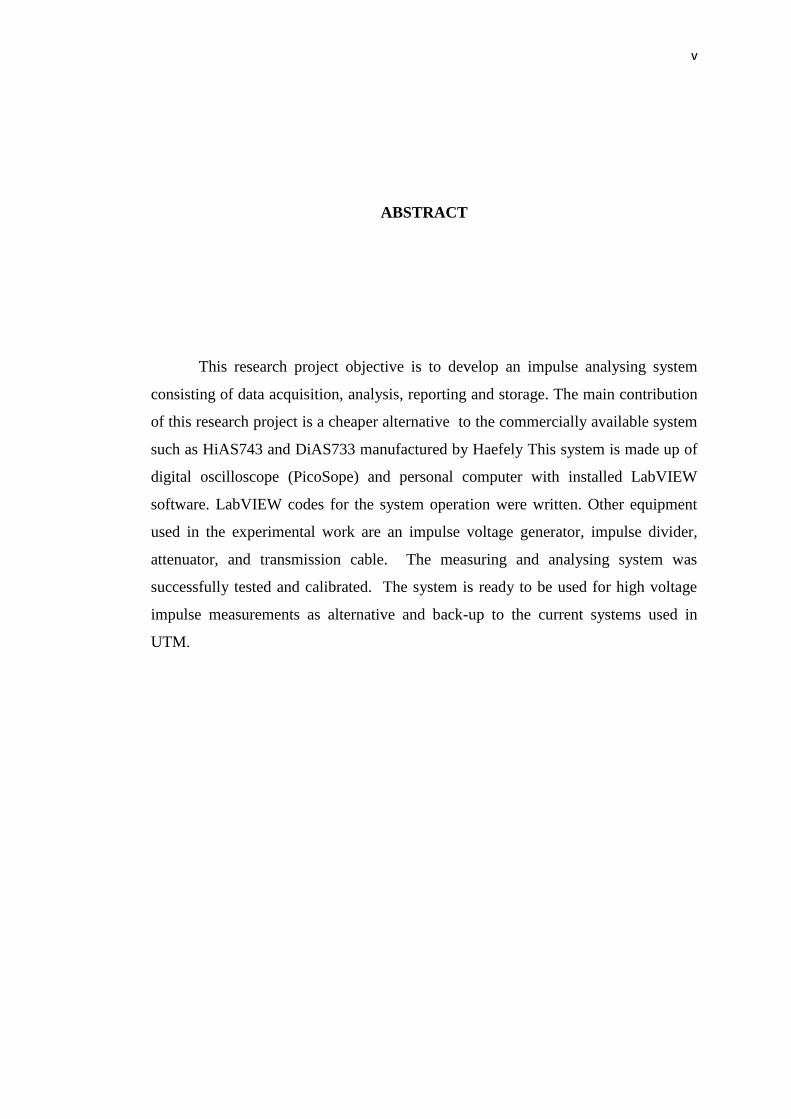
This research project objective is to develop an impulse analysing system
consisting of data acquisition, analysis, reporting and storage. The main contribution
of this research project is a cheaper alternative to the commercially available system
such as HiAS743 and DiAS733 manufactured by Haefely This system is made up of
digital oscilloscope (PicoSope) and personal computer with installed LabVIEW
software. LabVIEW codes for the system operation were written. Other equipment
used in the experimental work are an impulse voltage generator, impulse divider,
attenuator, and transmission cable. The measuring and analysing system was
successfully tested and calibrated. The system is ready to be used for high voltage
impulse measurements as alternative and back-up to the current systems used in
UTM.
vi
ABSTRAK
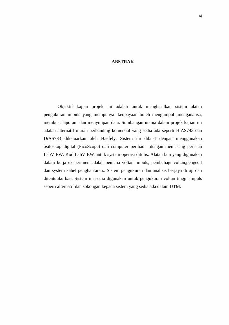
Objektif kajian projek ini adalah untuk menghasilkan sistem alatan
pengukuran impuls yang mempunyai keupayaan boleh mengumpul ,menganalisa,
membuat laporan dan menyimpan data. Sumbangan utama dalam projek kajian ini
adalah alternatif murah berbanding komersial yang sedia ada seperti HiAS743 dan
DiAS733 dikeluarkan oleh Haefely. Sistem ini dibuat dengan menggunakan
osiloskop digital (PicoScope) dan computer peribadi dengan memasang perisian
LabVIEW. Kod LabVIEW untuk system operasi ditulis. Alatan lain yang digunakan
dalam kerja eksperimen adalah penjana voltan impuls, pembahagi voltan,pengecil
dan system kabel penghantaran.. Sistem pengukuran dan analisis berjaya di uji dan
ditentuukurkan. Sistem ini sedia digunakan untuk pengukuran voltan tinggi impuls
seperti alternatif dan sokongan kepada sistem yang sedia ada dalam UTM.
vii
TABLE OF CONTENTS
CHAPTER TITLE PAGE
DECLARATION ii
DEDICATION iii
ACKNOWLEDGEMENT iv
ABSTRACT v
ABSTRAK vi
TABLE OF CONTENTS vii
LIST OF TABLES x
LIST OF FIGURES xii
LIST OF ABBREVIATIONS xiv
LIST OF APPENDICES xv
1 INTRODUCTION 1
1.1 Project Background 1
1.2 Project Problem Statement 2
1.3 Project Objectives 3
1.4 Project Scope 3
1.5 Project Contribution 3
1.6 Project Report Outline 4
2 LITERATURE REVIEW 5
2.1 Introduction 5
2.2 High Voltage Impulse Parameter 5
2.3 Current Impulse Parameter 9
viii
2.4 Generation of High Impulse Voltage 10
2.5 Requirement for Measurement Instrument and
Software
12
2.6 PicoScope Oscilloscope 13
2.7 Haefely HiAS 743 14
2.8 LabVIEW Programming 15
2.9 Critical Review on Impulse Measuring System 16
3 METHODOLOGY 17
3.1 Introduction 17
3.2 Process Flow 17
3.3 Project Flow explanation 18
3.4 Hardware Development 19
3.5 Software Development 26
3.6 Hardware and Software Integration 32
3.7 Data Measurement and Data Logging using
LabVIEW
33
4 RESULTS AND DISCUSSIONS 35
4.1 Introduction 35
4.2 Result Measurement Impulse Voltage Hardware
Development Block Diagram 1
35
4.3 Result Measurement Impulse Current Hardware
Development Block Diagram 2
41
4.4 Result Measurement High Voltage Impulse
Hardware Development Block Diagram 3
43
4.5 Result Software Development Improvement 47
4.6 Result Comparison Hardware and Software with IEC
standard
52
4.7 Result Comparison UTM HRIAS with Previous work
and Haefely Hias743
52
5 CONCLUSIONS AND RECOMMENDATIONS 57
ix
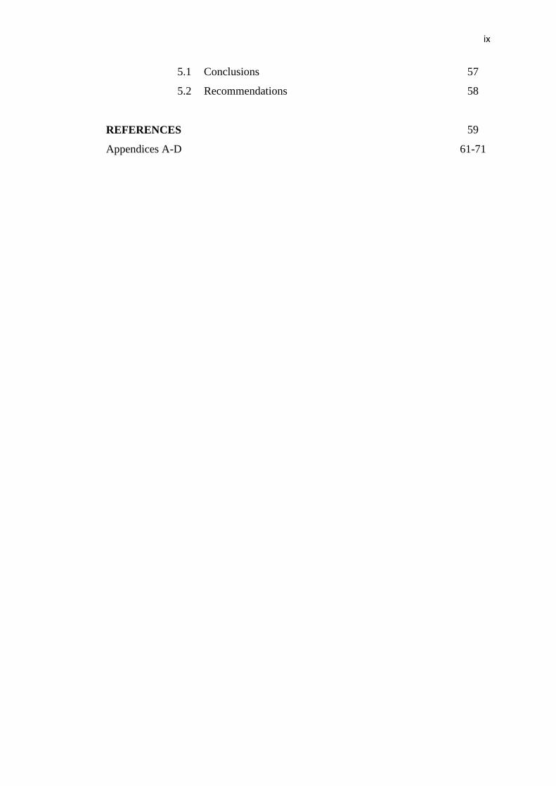
5.1 Conclusions 57
5.2 Recommendations 58
REFERENCES 59
Appendices A-D 61-71
x
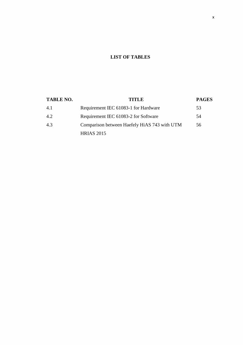
LIST OF TABLES
TABLE NO. TITLE PAGES
4.1 Requirement IEC 61083-1 for Hardware 53
4.2 Requirement IEC 61083-2 for Software 54
4.3 Comparison between Haefely HiAS 743 with UTM
HRIAS 2015
56
xi
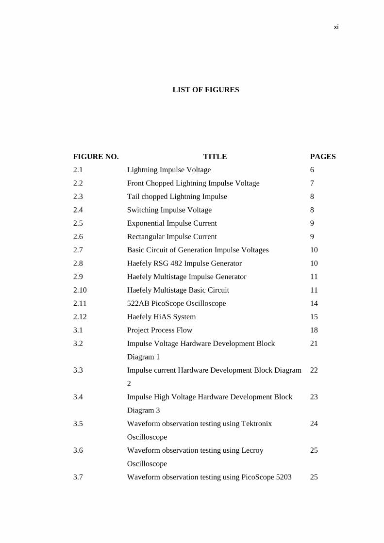
LIST OF FIGURES
FIGURE NO. TITLE PAGES
2.1 Lightning Impulse Voltage 6
2.2 Front Chopped Lightning Impulse Voltage 7
2.3 Tail chopped Lightning Impulse 8
2.4 Switching Impulse Voltage 8
2.5 Exponential Impulse Current 9
2.6 Rectangular Impulse Current 9
2.7 Basic Circuit of Generation Impulse Voltages 10
2.8 Haefely RSG 482 Impulse Generator 10
2.9 Haefely Multistage Impulse Generator 11
2.10 Haefely Multistage Basic Circuit 11
2.11 522AB PicoScope Oscilloscope 14
2.12 Haefely HiAS System 15
3.1 Project Process Flow 18
3.2 Impulse Voltage Hardware Development Block
Diagram 1
21
3.3 Impulse current Hardware Development Block Diagram
2
22
3.4 Impulse High Voltage Hardware Development Block
Diagram 3
23
3.5 Waveform observation testing using Tektronix
Oscilloscope
24
3.6 Waveform observation testing using Lecroy
Oscilloscope
25
3.7 Waveform observation testing using PicoScope 5203 25
xii
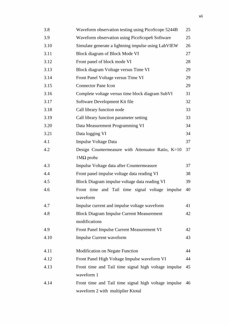
3.8 Waveform observation testing using PicoScope 5244B 25
3.9 Waveform observation using PicoScope6 Software 25
3.10 Simulate generate a lightning impulse using LabVIEW 26
3.11 Block diagram of Block Mode VI 27
3.12 Front panel of block mode VI 28
3.13 Block diagram Voltage versus Time VI 29
3.14 Front Panel Voltage versus Time VI 29
3.15 Connector Pane Icon 29
3.16 Complete voltage versus time block diagram SubVI 31
3.17 Software Development Kit file 32
3.18 Call library function node 33
3.19 Call library function parameter setting 33
3.20 Data Measurement Programming VI 34
3.21 Data logging VI 34
4.1 Impulse Voltage Data 37
4.2 Design Countermeasure with Attenuator Ratio, K=10
1MΩ probe
37
4.3 Impulse Voltage data after Countermeasure 37
4.4 Front panel impulse voltage data reading VI 38
4.5 Block Diagram impulse voltage data reading VI 39
4.6 Front time and Tail time signal voltage impulse
waveform
40
4.7 Impulse current and impulse voltage waveform 41
4.8
Block Diagram Impulse Current Measurement
modifications
42
4.9 Front Panel Impulse Current Measurement VI 42
4.10 Impulse Current waveform 43
4.11 Modification on Negate Function 44
4.12 Front Panel High Voltage Impulse waveform VI 44
4.13 Front time and Tail time signal high voltage impulse
waveform 1
45
4.14 Front time and Tail time signal high voltage impulse
waveform 2 with multiplier Ktotal
46
xiii
4.15 Front time and Tail time signal high voltage impulse
waveform 3 with countermeasure
47
4.16 Program measurement selection 48
4.17 Front Panel Main Program UTM HRIAS VI 48
4.18 Instrument setting VI 49
4.19 Impulse data save in bitmap 49
4.20 Impulse data save in excel folder 49
4.21 Impulse data save in excel spreadsheet 50
4.22 Block Diagram Main UTM HRIAS VI 50
xiv
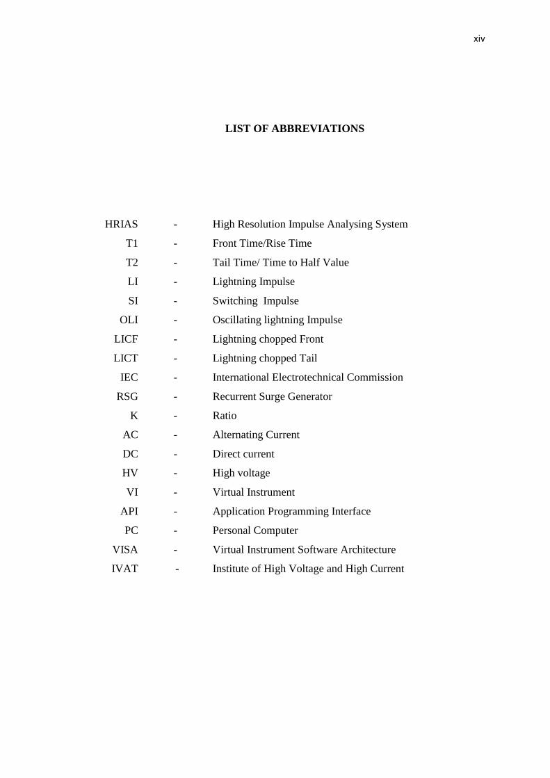
LIST OF ABBREVIATIONS
HRIAS - High Resolution Impulse Analysing System
T1 - Front Time/Rise Time
T2 - Tail Time/ Time to Half Value
LI - Lightning Impulse
SI - Switching Impulse
OLI - Oscillating lightning Impulse
LICF - Lightning chopped Front
LICT - Lightning chopped Tail
IEC - International Electrotechnical Commission
RSG - Recurrent Surge Generator
K - Ratio
AC - Alternating Current
DC - Direct current
HV - High voltage
VI - Virtual Instrument
API - Application Programming Interface
PC - Personal Computer
VISA - Virtual Instrument Software Architecture
IVAT - Institute of High Voltage and High Current
xv
LIST OF APPENDICES
APPENDIX TITLE PAGE
A IEC Standard Requirement 61
B Project Research Gantt Chart 66
C API Function Call 67
D Instrument Data sheet 68
1
CHAPTER 1
INTRODUCTION
1.1 Project Background
High voltage testing or insulation testing is essential for electrical engineers
and researchers to ensure the electrical equipment to be capable of withstanding
overvoltage, which meets the requirement of its service. In electrical field
engineering, the testing of voltages are divided into three, namely the direct voltages
(DC), power frequency alternating voltages (AC) and impulse voltage. This research
thesis study focuses on impulse voltage area knowledge, which then is used to
develop a high resolution impulse measurement system. High impulse voltage is
required for the testing purpose to simulate overvoltage in transmission lines and
electrical apparatus that are stressed by two transient overvoltage conditions, which
are lighting strike and switching operation.
In order to standardize the high voltage testing, international or national
standard such as Electrotechnical Commission (IEC) specification is a necessity to
follow and satisfy. This specification outlines the detail of testing technique,
requirement for equipment, acceptable limit and procedure that meet the requirement
of users and manufactures. The standard requirement reference for developing
measuring impulse voltages is IEC 61083-1 that is required for instrument used for
measuring the high voltage and IEC 61083-2, an evaluation software that uses
determination impulse voltage parameter. IEC 60060-1 is a high voltage test
technique which testing the requirement with general definition and IEC 60060 -2 is
2
a high voltage test technique measuring system requirement that need to be fulfilled.
With this IEC standard given, it is important to distinguish between the equipment
and software that is used in the design of high resolution impulse measurement
system.
UTM High Resolution Impulse Analyzing System (UTM HRIAS 2015) is
developed in UTM, which function is to measure the impulse. It has features to do,
analyze and record an impulse.
1.2 Project Problem Statement
In commercial industry, there are several products that are related to the
impulse measurement system, such as Hias 743 and Dias 733; manufactured by
Haefely. However, the cost for the current facilities of impulse voltage is expensive.
There are also some difficulties issues in HV impulse acquisition and analysis
regarding the digital recorder. This is because, due to digitizing, the information
about the measured signal is lost between neighboring sampling point. The digital
recorder with lowest amplitude resolution always gets inaccurate and worse data
analysis. A lower sampling rate digital recorder affects the evaluation of impulse
parameter and has a possibility for superposed oscillation impulse. Besides, users
always spending time to calculate and define the impulse parameter manually, since
there is no automatic function cursor on the digital recorder. Furthermore, the users
also have difficulties to use some old version digital recorders that are not user
friendly in terms of data saving, due to capacity storage and data analysis report. The
other issue is to verify compliance with the IEC standard for IEC 61083-1 and IEC
61083-2 that are required for the instrument and software. Moreover, standard IEC
60060 relate impulse high voltage testing technique needs to be verified, too.
3
1.3 Project Objective
The objectives for this research are stated as follows:
i. To develop a new impulse analysing system consisting both hardware
and software implementation following international standard
requirement;
ii. To test and calibrate the developed system;
iii. To compare the system performance against standard and commercial
system.
1.4 Project Scope
This project focuses on utilizing the facilities related to impulse system in
UTM IVAT laboratory. A study and testing equipment related to impulse system is
done. Simulation and measurement testing are done using LabVIEW. Once the study
and testing are completed, the hardware and software are integrated, to complete the
full testing, analyzing and recording the impulse parameter. Hence, the UTM HRIAS
system implemented in UTM is for researchers and students to analyze and study.
1.5 Project Contribution
The significant contribution for this project is a cheaper alternative system
made for analyzing impulse. This system has some features, which are capable for
data reading, analysis and data storage according to standard. This system is used as
a backup to the current system used in UTM.
4
1.6 Project Report Outline
This thesis report consists of five chapters. Chapter 1 is an introduction of the
research project. It covers the background, problem statement, objectives,
contribution and scopes of the research study.
Chapter 2 is a literature review. It provides the detail of theories and standard
of previous works related to impulse measurement system.
Chapter 3 is a research methodology that consists of the research
methodology, the flow chart of the research. It describes the hardware and software
approaches in experiment.
Chapter 4 analyzes the results and discussion from experiment done in IVAT
laboratory for this research. The UTM HRIAS LabVIEW software modification and
comparison with previous research will be discussed in this chapter
The last chapter, which is Chapter 5 will explains the conclusion and the
suggestion for future work.
59
REFERENCES
1. V. K. M.S Naidu (2009), HIGH VOLTAGE ENGINEERING, New Delhi:
McGraw Hill.
2. Carlos R. Hall Barbosa et all (2014), "Validation of a system for Evaluation of
High- Voltage IMpulse According to IEC 60060:2010," IEEE, p. 1, 2014.
3. IEC61083-1:2001, "Instruments and software used for measurement in high
voltage impulse test- part 1requirement for instrument," British standard, 2001
.
4. IEC61083-2:2013, "Instrument and software used in high voltage and high
current tests- part 2 requirement for software for test with impulse voltage and
current," British Standard, 2013.
5. Shigemitsu Okabe Jun et all (2013), "Discussion on standard waveform in
lightning impulse voltage test," IEEE, vol. 20, no. 1, pp. 147-155
.
6. I. P. E. Society, "IEEE Standard for High-Voltage Testing Techniques," IEEE
Standard Asscociation.
7. H. M. Ryan (2013), High-Voltage Engineering and Testing, United Kingdom:
The Institution of Engineering and Technology.
8. K. F. Dieter Kind (2001), High Voltages Test Techniques, London: Newnes.
60
9. A. J. Schwab (1972), High voltage Measurement Technique,
Cambridge,Massachuchetts and London: MIT press,.
10. M. N. B. A. Razak (2014), High Resolution impulse Analysing System,
Universiti Teknologi Malaysia.
11. T. M. N. Rick Bitter (2001), LabVIEW advanced programming, CRC Pess.
12. N. Instrument (2009), labVIEW Core1 and 2 Manual, Austin Texas: National
Instrument Corporation
.
13. P. s. Technology, "PicoScope 5000 Series- PC Oscillocope Series," Pico
Technology Limited, 2010.
14. H. h. v. test, "Hias 743 data sheet," Haefely high voltage test, basel
switzerland.
15. S. Tumanski (2006), Principle Of Electrical Measurement, Florida: Taylor and
Francis.
16. P. A. Blume (2013), LabVIEW style Book, vol. 20, US: Prentice Hall, pp.
147-155.
17. R. W. Larsen (2011), LabVIEW for Engineer, US: Prentice Hall.
18. S. a. M. Sasaki, "Resolution of Digital Recorder and Evaluated Impulse
voltage waveform Parameters," IEEE, pp. 978-981, 2007.
19. S. Folea (2011), LabVIEW Practical Application and Solution, Rijeka,Croatia:
InTech.
20. K. Schon (2013) High Impulse voltage and Current Measurement
Technique,Switzerland Springer