Embed Size (px)
Citation preview
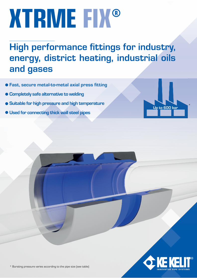
Fast, secure metal-to-metal axial press fi tting
Completely safe alternative to welding
Suitable for high pressure and high temperature
Used for connecting thick wall steel pipes
High performance fi ttings for industry, energy, district heating, industrial oils and gases
*
* Bursting pressure varies according to the pipe size (see table)
Up to 600 bar
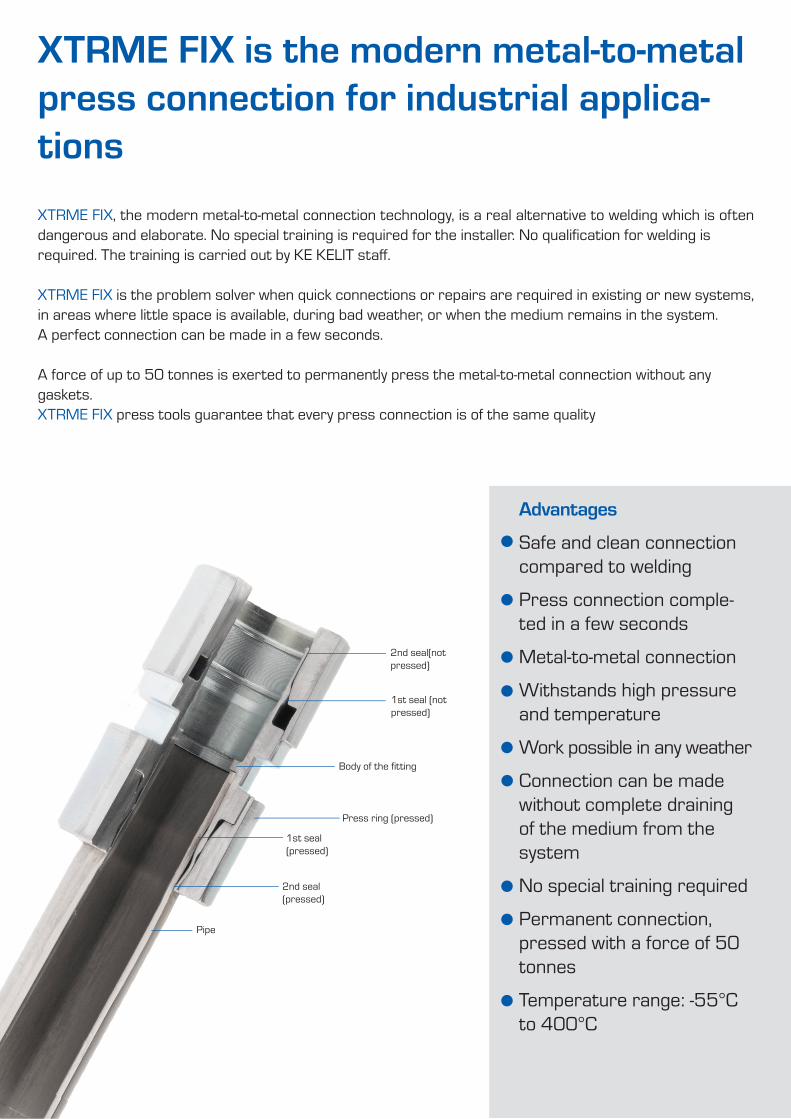
2nd seal(not pressed)
1st seal (not pressed)
Body of the fi tting
Press ring (pressed)
1st seal(pressed)
2nd seal(pressed)
Pipe
XTRME FIX is the modern metal-to-metal press connection for industrial applica-tionsXTRME FIX, the modern metal-to-metal connection technology, is a real alternative to welding which is often dangerous and elaborate. No special training is required for the installer. No qualifi cation for welding is required. The training is carried out by KE KELIT staff .
XTRME FIX is the problem solver when quick connections or repairs are required in existing or new systems, in areas where little space is available, during bad weather, or when the medium remains in the system. A perfect connection can be made in a few seconds.
A force of up to 50 tonnes is exerted to permanently press the metal-to-metal connection without any gaskets.XTRME FIX press tools guarantee that every press connection is of the same quality
Advantages
Safe and clean connection compared to welding
Press connection comple-ted in a few seconds
Metal-to-metal connection
Withstands high pressure and temperature
Work possible in any weather
Connection can be made without complete draining of the medium from the system
No special training required
Permanent connection, pressed with a force of 50 tonnes
Temperature range: -55°C to 400°C
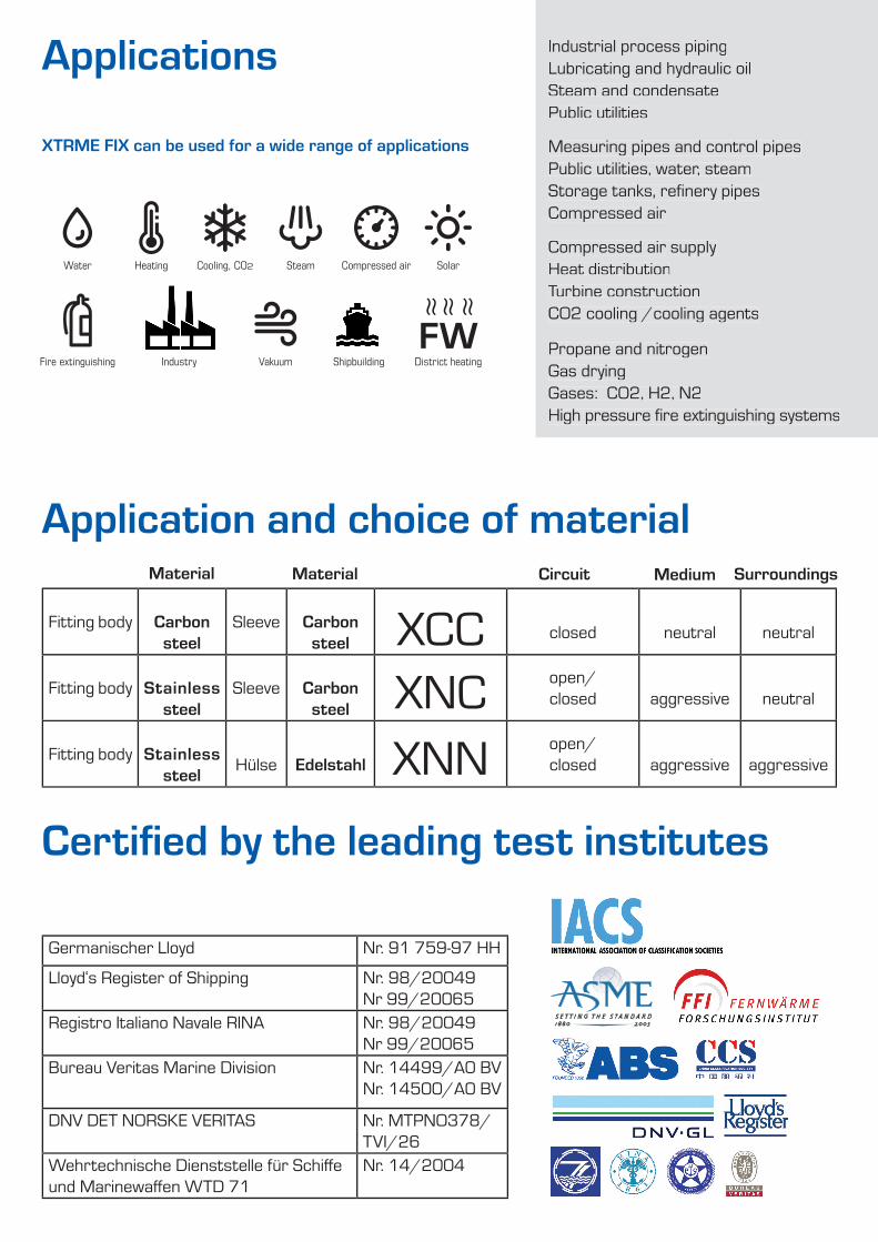
Applications
XTRME FIX can be used for a wide range of applications
Industrial process pipingLubricating and hydraulic oilSteam and condensatePublic utilities
Measuring pipes and control pipesPublic utilities, water, steamStorage tanks, refi nery pipesCompressed air
Compressed air supplyHeat distributionTurbine constructionCO2 cooling /cooling agents
Propane and nitrogen Gas dryingGases: CO2, H2, N2High pressure fi re extinguishing systems
Germanischer Lloyd Nr. 91 759-97 HH
Lloyd‘s Register of Shipping Nr. 98/20049Nr 99/20065
Registro Italiano Navale RINA Nr. 98/20049Nr 99/20065
Bureau Veritas Marine Division Nr. 14499/A0 BVNr. 14500/A0 BV
DNV DET NORSKE VERITAS Nr. MTPNO378/TVI/26
Wehrtechnische Dienststelle für Schiff e und Marinewaff en WTD 71
Nr. 14/2004
Industrial process pipingLubricating and hydraulic oilSteam and condensatePublic utilities
Measuring pipes and control pipesPublic utilities, water, steamStorage tanks, refi nery pipesCompressed air
Compressed air supplyHeat distributionTurbine constructionCO2 cooling /cooling agents
Propane and nitrogen Gas dryingGases: CO2, H2, N2High pressure fi re extinguishing systems
Certifi ed by the leading test institutes
Water Heating Cooling, CO2 Steam Compressed air Solar
Fire extinguishing Industry Vakuum Shipbuilding District heatingFW
≈ ≈ ≈
Fitting body Carbon steel
Sleeve Carbon steel XCC closed neutral neutral
Fitting body Stainless steel
Sleeve Carbon steel XNC open/
closed aggressive neutral
Fitting body Stainless steel Hülse Edelstahl XNN open/
closed aggressive aggressive
Circuit Medium SurroundingsMaterial Material
Application and choice of material
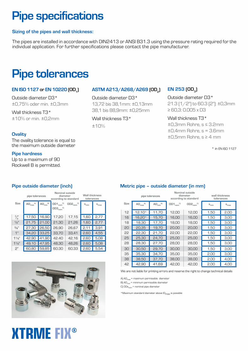
Pipe specificationsSizing of the pipes and wall thickness:
The pipes are installed in accordance with DIN2413 or ANSI B31.3 using the pressure rating required for the individual application. For further specifications please contact the pipe manufacturer.
Size ADmaxA) ADmin
B) OD1nomC)
OD3nomC)
OD2nomC) smin smax
3/8 “ 17,50 16,90 17,20 17,15 1,60 2,77½“ 21,75 21,00 21,30 21,26 1,60 2,77¾“ 27,30 26,50 26,90 26,67 2,11 3,911“ 34,20 33,25 33,70 33,41 2,60 4,55
1¼“ 42,90 41,90 42.40 42,16 2,60 5,081½“ 49,10 47,95 48,30 48,26 2,60 5,082“ 60,80 59,85 60.30 60.33 2,60 5,54
Wall thickness tolerances
A) ADmax = maximum permissible diameterB) ADmin = minimum permissible diameter C) ODxnom = nominal pipe diameter *Maximum standard diameter above IDmax is possible
Pipe outside diameter (inch)
pipe tolerances
Size ADmaxA) ADmin
B) OD1nomC) OD2nom
C) smin smax
12 12,10* 11,70 12,00 12,00 1,50 2,0016 16,20* 15,70 16,00 16,00 1,50 3,0018 18,30 17,70 18,00 18,00 1,50 3,0020 20,35 19,70 20,00 20,00 1,50 3,0022 22,30 21,70 22,00 22,00 1,50 3,0025 25,30 24,70 25,00 25,00 1,50 3,0028 28,30 27,70 28,00 28,00 1,50 3,00
30 30,50 29,70 30,00 30,00 1,50 3,0035 35,30 34,70 35,00 35,00 2,00 3,0038 38,50 37,70 38,00 38,00 2,00 4,0042 42,90 41,69 42,00 42,00 2,00 4,00
wall thickness tolerances
pipe tolerancesNominal outside
diameteraccording to standard
We are not liable for printing errors and reserve the right to change technical details
Metric pipe – outside diameter (in mm)
EN 253 (OD3)
Outside diameter D3* 21.3 (1/2") to 60.3 (2"): ±0,3mm ≥ 60,3: 0.005 x D3
Wall thickness T3* ±0,3mm Rohre, s ≤ 3.2mm ±0,4mm Rohre, s = 3.6mm ±0,5mm Rohre, s ≥ 4 mm
EN ISO 1127 or EN 10220 (OD1)
Outside diameter D3* ±0,75% oder min. ±0,3mm
Wall thickness T3* ±10% or min. ±0,2mm
Pipe tolerances
OvalityThe ovality tolerance is equal to the maximum outside diameter
Pipe hardnessUp to a maximum of 90 Rockwell B is permitted.
ASTM A213/A268/A269 (OD2)
Outside diameter D3* 13,72 bis 38,1mm: ±0,13mm 38,1 bis 88,9mm: ±0,25mm
Wall thickness T3*±10%
* in EN ISO 1127
Nominal outside diameter
according to standard
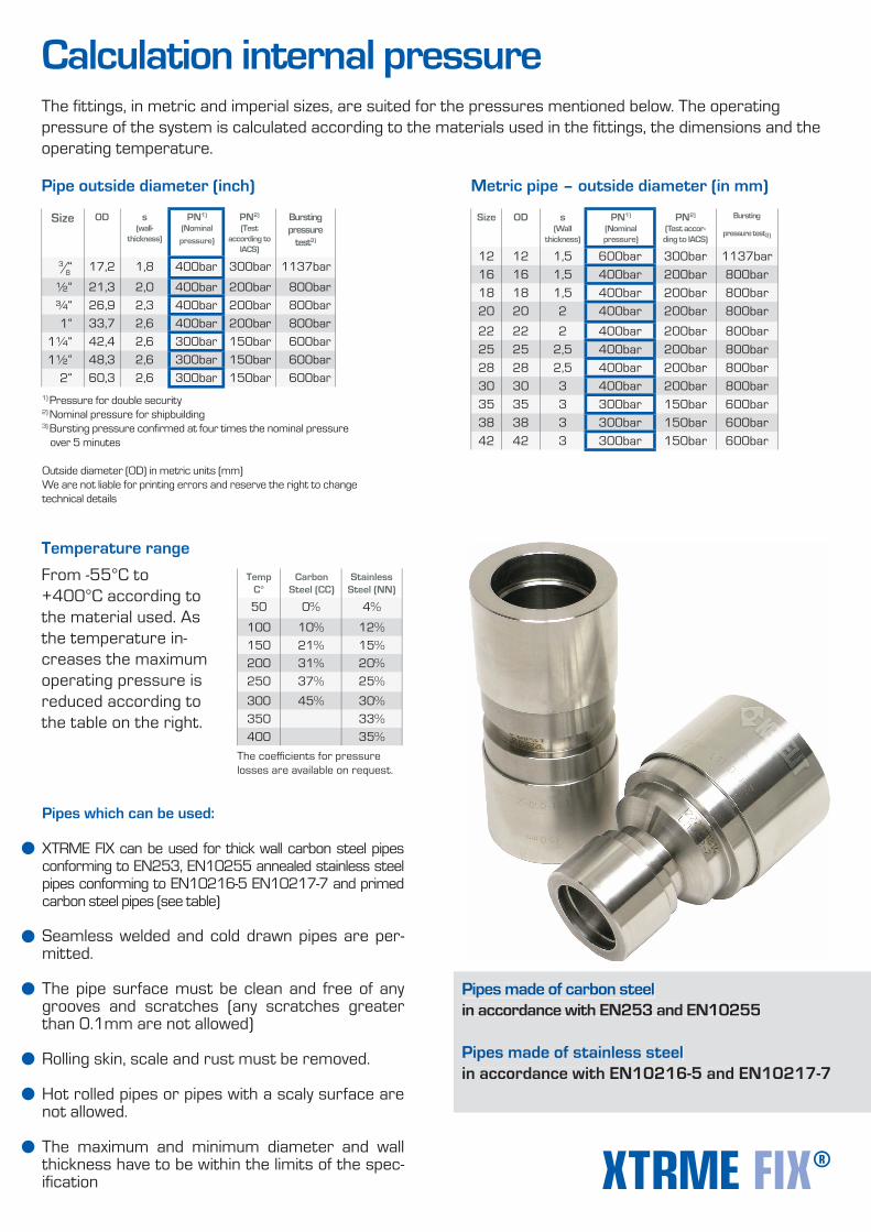
From -55°C to +400°C according to the material used. As the temperature in-creases the maximum operating pressure is reduced according to the table on the right.
TempC°
CarbonSteel (CC)
StainlessSteel (NN)
50 0% 4%
100 10% 12%150 21% 15%200 31% 20%250 37% 25%300 45% 30%350 33%400 35%
The coeffi cients for pressure losses are available on request.
Temperature range
Pipes which can be used:
XTRME FIX can be used for thick wall carbon steel pipes conforming to EN253, EN10255 annealed stainless steel pipes conforming to EN10216-5 EN10217-7 and primed carbon steel pipes (see table)
Seamless welded and cold drawn pipes are per-mitted.
The pipe surface must be clean and free of any grooves and scratches (any scratches greater than 0.1mm are not allowed)
Rolling skin, scale and rust must be removed.
Hot rolled pipes or pipes with a scaly surface are not allowed.
The maximum and minimum diameter and wall thickness have to be within the limits of the spec-ifi cation
Pipes made of carbon steel in accordance with EN253 and EN10255
Pipes made of stainless steel in accordance with EN10216-5 and EN10217-7
Pipes made of carbon steel in accordance with EN253 and EN10255
Pipes made of stainless steel in accordance with EN10216-5 and EN10217-7
Size OD s(wall-
thickness)
PN1) (Nominal
pressure)
PN2)
(Test according to
IACS)
Bursting pressure
test3)
3/8“ 17,2 1,8 400bar 300bar 1137bar
½“ 21,3 2,0 400bar 200bar 800bar¾“ 26,9 2,3 400bar 200bar 800bar1“ 33,7 2,6 400bar 200bar 800bar
1¼“ 42,4 2,6 300bar 150bar 600bar1½“ 48,3 2,6 300bar 150bar 600bar
2“ 60,3 2,6 300bar 150bar 600bar
Pipe outside diameter (inch)
Size OD s(Wall
thickness)
PN1) (Nominal pressure)
PN2)
(Test accor-ding to IACS)
Bursting
pressure test3)
12 12 1,5 600bar 300bar 1137bar16 16 1,5 400bar 200bar 800bar18 18 1,5 400bar 200bar 800bar20 20 2 400bar 200bar 800bar
22 22 2 400bar 200bar 800bar25 25 2,5 400bar 200bar 800bar28 28 2,5 400bar 200bar 800bar30 30 3 400bar 200bar 800bar35 35 3 300bar 150bar 600bar38 38 3 300bar 150bar 600bar42 42 3 300bar 150bar 600bar
Metric pipe – outside diameter (in mm)
1) Pressure for double security2) Nominal pressure for shipbuilding3) Bursting pressure confi rmed at four times the nominal pressure over 5 minutes
Outside diameter (OD) in metric units (mm)We are not liable for printing errors and reserve the right to change technical details
Calculation internal pressureThe fi ttings, in metric and imperial sizes, are suited for the pressures mentioned below. The operating pressure of the system is calculated according to the materials used in the fi ttings, the dimensions and the operating temperature.
KE KELIT Kunststoffwerk Gesellschaft m.b.H.A 4020 Linz, Ignaz-Mayer-Straße 17Austria, Europe
TELEFON +43 (0) 50 779FAX +43 (0) 50 779 318E-MAIL [email protected] www.kekelit.com
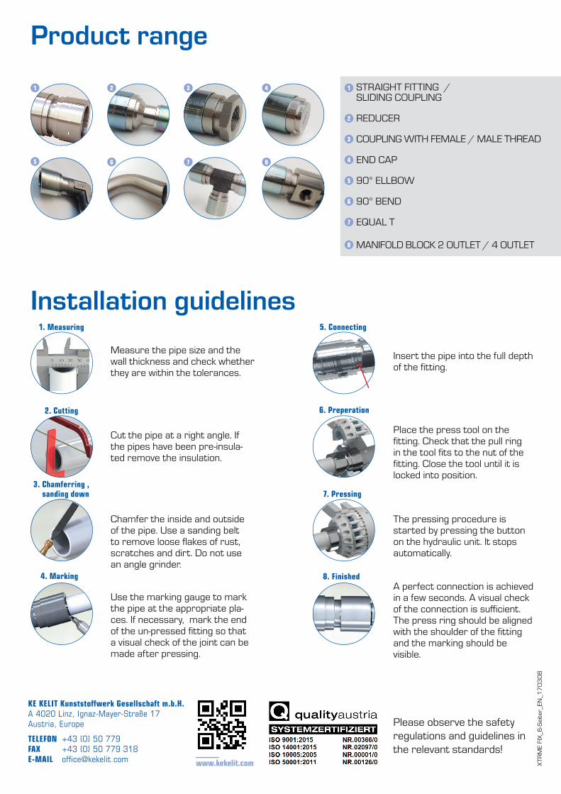
STRAIGHT FITTING / SLIDING COUPLING
REDUCER
COUPLING WITH FEMALE / MALE THREAD
END CAP
90° ELLBOW
90° BEND
EQUAL T
MANIFOLD BLOCK 2 OUTLET / 4 OUTLET
Product range1 2 3 4
5 6 7 8
1
2
3
4
5
6
7
8
Measure the pipe size and the wall thickness and check whether they are within the tolerances.
Cut the pipe at a right angle. If the pipes have been pre-insula-ted remove the insulation.
Chamfer the inside and outside of the pipe. Use a sanding belt to remove loose fl akes of rust, scratches and dirt. Do not use an angle grinder.
Use the marking gauge to mark the pipe at the appropriate pla-ces. If necessary, mark the end of the un-pressed fi tting so that a visual check of the joint can be made after pressing.
Insert the pipe into the full depth of the fi tting.
Place the press tool on the fi tting. Check that the pull ring in the tool fi ts to the nut of the fi tting. Close the tool until it is locked into position.
The pressing procedure is started by pressing the button on the hydraulic unit. It stops automatically.
A perfect connection is achieved in a few seconds. A visual check of the connection is suffi cient. The press ring should be aligned with the shoulder of the fi tting and the marking should be visible.
1. Measuring
2. Cutting
3. Chamferring , sanding down
4. Marking
5. Connecting
6. Preperation
7. Pressing
8. Finished
Installation guidelines
Please observe the safety regulations and guidelines in the relevant standards!
XTRM
E FI
X_6-
Seite
r_EN
_170
308