Embed Size (px)
Citation preview
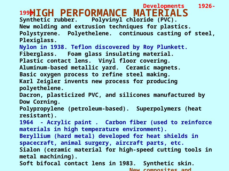
HIGH PERFORMANCE MATERIALS
Developments 1926- 1990 Synthetic rubber. Polyvinyl chloride (PVC). New molding and extrusion techniques for plastics. Polystyrene. Polyethelene. continuous casting of steel, Plexiglass. Nylon in 1938. Teflon discovered by Roy Plunkett.Fiberglass. Foam glass insulating material. Plastic contact lens. Vinyl floor covering.Aluminum-based metallic yard. Ceramic magnets.Basic oxygen process to refine steel making.Karl Zeigler invents new process for producing polyethelene. Dacron, plasticized PVC, and silicones manufactured by Dow Corning. Polypropylene (petroleum-based). Superpolymers (heat resistant).1964 - Acrylic paint . Carbon fiber (used to reinforce materials in high temperature environment).Beryllium (hard metal) developed for heat shields in spacecraft, animal surgery, aircraft parts, etc.Sialon (ceramic material for high-speed cutting tools in metal machining). Soft bifocal contact lens in 1983. Synthetic skin. New composites and lightweight steel
• SMART MATERIALS- which adjust to the requirements
"smart materials" also called intelligent materials or active materials describes a group of material systems with unique properties.
The technological field of “smart materials” is not transparent or clearly structured. It has evolved over the past decades with increasing pace during the 1990s to become what it is today.
• Smart materials, Intelligent Materials, Active Materials, Adaptive Materials and to some extent “actuators” and “sensors” are almost always used interchangeably.
• Active materials - two groups. 1. The “classical” active materials as viewed by the academic
community and is characterized by the type of response these materials generate.
2. Consists of materials that respond to stimuli with a change in a key material property, eg.electrical conductivity or viscosity
• [Mention of medicines, packed items which will indicate the life with change in time, environment, decay etc; dress materials which will adjust with the human conditions etc. etc.]

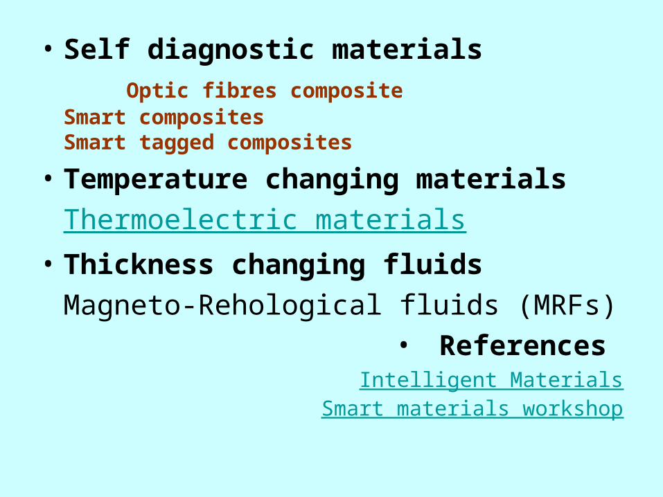
• Self diagnostic materials Optic fibres composite
Smart compositesSmart tagged composites
• Temperature changing materials
Thermoelectric materials
• Thickness changing fluids
Magneto-Rehological fluids (MRFs)
• References Intelligent Materials
Smart materials workshop
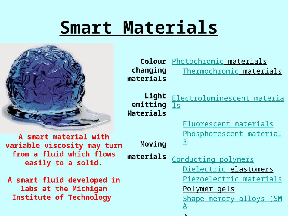
Smart Materials
Colour changing materials
Light emittingMaterials
Moving
materials
Photochromic materialsThermochromic materials
Electroluminescent materialsFluorescent materialsPhosphorescent materials
Conducting polymersDielectric elastomersPiezoelectric materialsPolymer gels
Shape memory alloys (SMA)
A smart material with variable viscosity may turn from a fluid which flows easily to a solid.
A smart fluid developed in labs at
the Michigan Institute of Technology
Smart Materials• "Smart" materials respond to environmental
stimuli with particular changes in some variables. Also called responsive materials.
Depending on changes in some external conditions, "smart" materials change either their properties (mechanical, electrical, appearance), their structure or composition, or their functions.
Mostly, "smart" materials are embedded in systems whose inherent properties can be favorably changed to meet performance needs.
Also termed as Responsive Materials
• Self diagnostic materials Optic fibres composite
Smart compositesSmart tagged composites
• Temperature changing materials
Thermoelectric materials
• Thickness changing fluids
Magneto-Rehological fluids (MRFs)
• References Intelligent Materials
Smart materials workshop
Shape Memory Alloys (SMA)
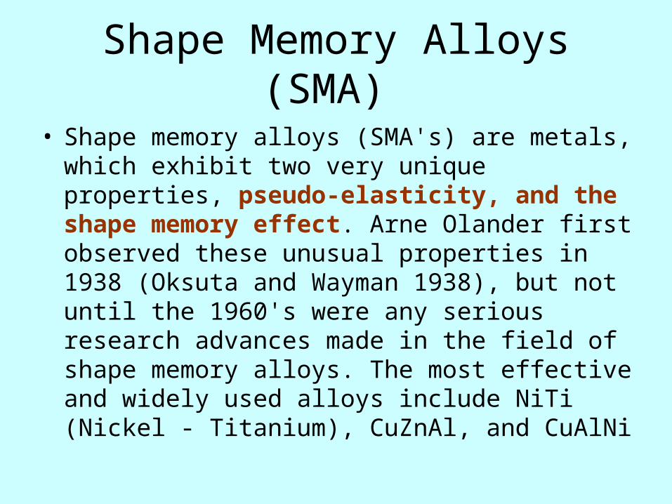
• Shape memory alloys (SMA's) are metals, which exhibit two very unique properties, pseudo-elasticity, and the shape memory effect. Arne Olander first observed these unusual properties in 1938 (Oksuta and Wayman 1938), but not until the 1960's were any serious research advances made in the field of shape memory alloys. The most effective and widely used alloys include NiTi (Nickel - Titanium), CuZnAl, and CuAlNi

Shape Memory Alloys (SMA)
• Shape memory alloys (SMA's) are metals, which exhibit two very unique properties, pseudo-elasticity, and the shape memory effect.
• The most effective and widely used alloys include NiTi (Nickel - Titanium), CuZnAl, and CuAlNi

Applications of Shape Memory Alloys
• Aeronautical Applications: • Surgical Tools: • Muscle Wires

SHAPE MEMORY EFFECT
Implemented in:
• Coffee pots
• The space shuttle
• Thermostats
• Vascular Stets
• Hydraulic Fittings (for Airplanes)

SHAPE MEMORY EFFECT
Implemented in:
• Coffee pots
• The space shuttle
• Thermostats
• Vascular Stets
• Hydraulic Fittings (for Airplanes)

Microscopic and Macroscopic Views of the Two Phases of Shape Memory Alloys

Microscopic Diagram of the Shape Memory Effect

How Shape Memory Alloys Work
The Martensite and Austenite phases

Applications of Shape Memory Alloys
• Aeronautical Applications: • Surgical Tools: • Muscle Wires

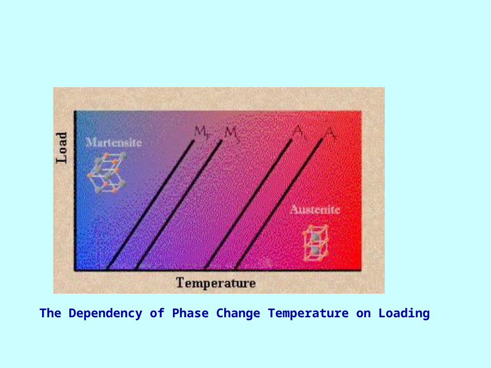
The Dependency of Phase Change Temperature on Loading

Pseudo-elasticity
Load Diagram of the pseudo-elastic effect Occurring
Applications in which pseudo-elasticity is
used are:
Eyeglass Frames Under garments Medical Tools Cellular Phone
Antennae Orthodontic Arches

Advantages and Disadvantages of SMAs
• Bio-compatibility • Diverse Fields of Application • Good Mechanical Properties (strong, corrosion resistant)
Relatively expensive to manufacture and machine. Most SMA's have poor fatigue properties; this means that while under the same loading conditions (i.e. twisting, bending, compressing) a steel component may survive for more than one hundred times more cycles than an SMA element

Ferromagnetic Shape Memory Alloys (FSMA) –
• Ferromagnetic Shape Memory Alloys (FSMA) Recently discovered class of actuator material, Magnetically driven actuation (field intensity varies, about 3KG and larger) and
• large strains (around 6%). • FSMA are still in the development phase• Alloys in the Ni-Mn-Ga ternary.• FSMAs are ferromagnetic alloys which also
support the shape memory effect.
OPTICAL FIBRE
• Made of extremely pure silica. • Thinner than a human hair and stronger than
a steel fibre of similar thickness. It can carry thousands of times more information than a copper wire!
• Optical fibre cables have the advantage of being lighter and taking less space than copper wire cables for the same information capacity.
Fabrication of Optical Fibres• The best cakes are made of the best ingredients. • To make a good optical fibre, we need to start with good quality materials, that is
highly purified materials.
• The presence of impurities alter the optical properties of the fibre.
• There are several ways to manufacture optical fibres:
• Directly drawing the fibre from what is called a preform.
• The fibre is then drawn from the preform
i) Direct Techniques
Two methods can be used to draw a fibre directly: 1. Double Crucible method 2. Rod in Tube method

1. Double Crucible
The molten core glass is placed in the inner crucible.
The molten cladding glass is placed in the outer crucible.
The two glasses come together at the base of the outer cucible and a fibre is
drawn. Long fibres can be produced (providing you don't let the content of the crucibles
run dry!). Step-index fibres and graded-index
fibres can be drawn with this method.
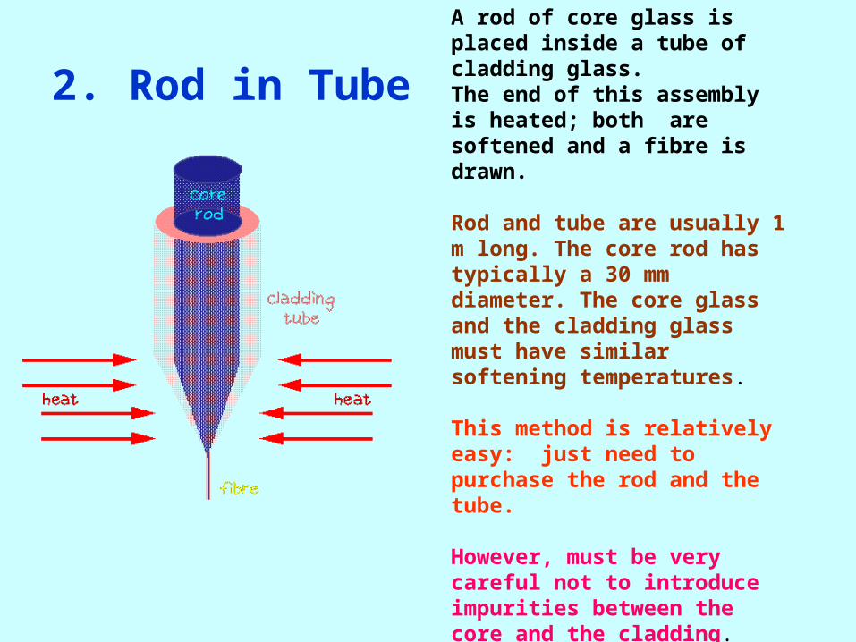
2. Rod in Tube A rod of core glass is placed inside a tube of cladding glass. The end of this assembly is heated; both are softened and a fibre is drawn.
Rod and tube are usually 1 m long. The core rod has typically a 30 mm diameter. The core glass and the cladding glass must have similar softening temperatures.
This method is relatively easy: just need to purchase the rod and the tube.
However, must be very careful not to introduce impurities between the core and the cladding.
ii) Deposition Techniques
• Most optical fibres are made from preforms. The preforms are made by deposition of silica and various dopants from mixing certain chemicals; the fibre is then drawn from the preform.
• Many techniques are used to make preforms. Among them:
• · Modified Chemical Vapour Deposition or MCVD • · Plasma-Enhanced Modified Chemical Vapour
Deposition or PMCVD • · Outside Vapour Deposition or OVD • · Axial Vapour Deposition or AVD
The Chemicals
• Oxygen (O2) and silicon tetrachloride (SiCl4) react to make silica (SiO2).
• Pure silica is doped with other chemicals such as boron oxide (B2O3), germanium dioxide (GeO2) and phosphorus pentoxide (P2O5) are used to change the refractive index of the glass.
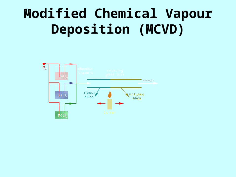
Modified Chemical Vapour Deposition (MCVD)

• The chemicals are mixed inside a glass tube that is rotating on a lathe.
• • They react and extremely fine particles
of germano or phosphoro silicate glass are deposited on the inside of the tube.
• A travelling burner moving along the tube:
causes a reaction to take place and then fuses the deposited material.
• The preform is deposited layer by layer starting first with the cladding layers and followed by the core layers.
• Varying the mixture of chemicals changes the refractive index of the glass.
• When the deposition is complete, the tube is collapsed at 2000 C into a preform of the purest silica with a core of different composition.
• The preform is then put into a furnace for drawing.
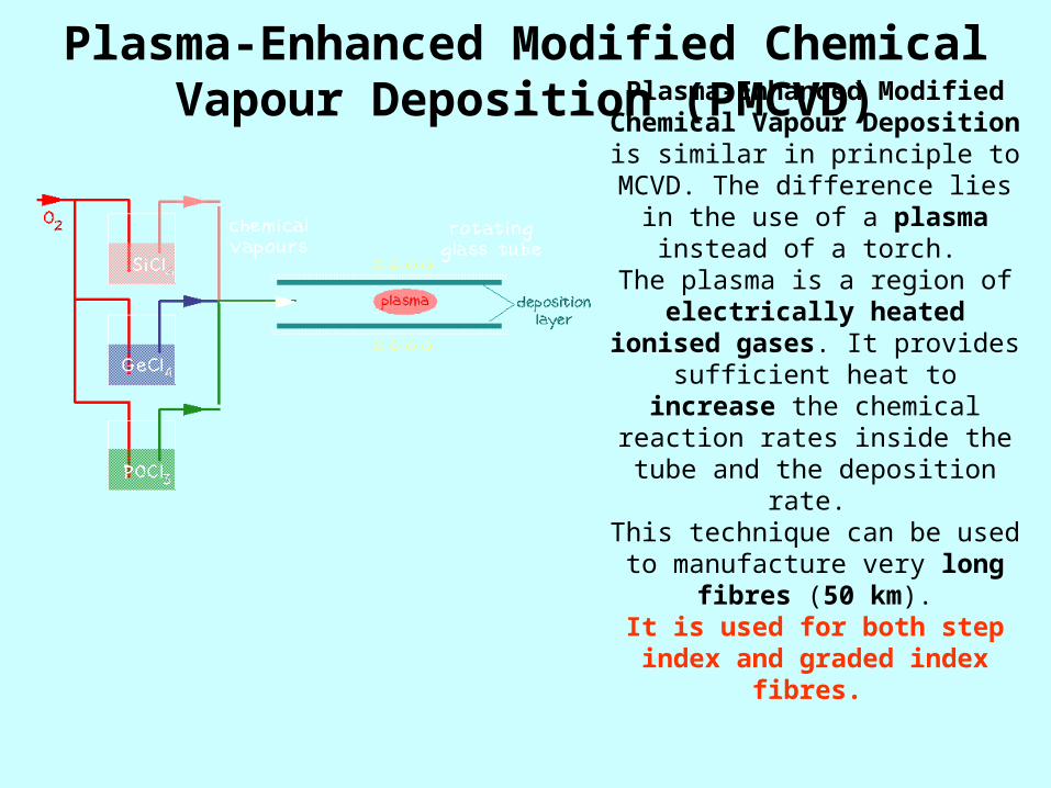
Plasma-Enhanced Modified Chemical Vapour Deposition (PMCVD)
Plasma-Enhanced Modified Chemical Vapour Deposition is similar in principle to MCVD. The
difference lies in the use of a plasma instead of a torch. The plasma is a region of
electrically heated ionised gases. It provides sufficient heat to
increase the chemical reaction rates inside the tube and the
deposition rate. This technique can be used to
manufacture very long fibres (50 km).
It is used for both step index and graded index fibres.
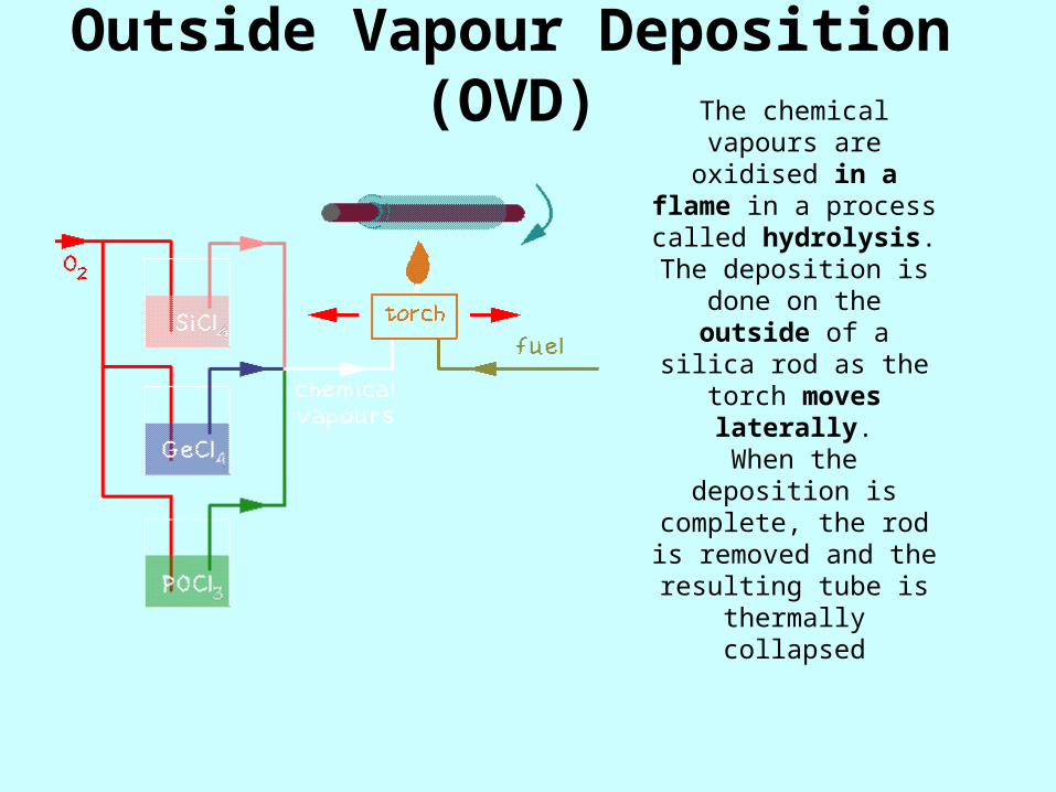
Outside Vapour Deposition (OVD)
The chemical vapours are oxidised in a flame in
a process called hydrolysis.
The deposition is done on the outside of a silica rod as the torch moves
laterally.When the deposition is
complete, the rod is removed and the
resulting tube is thermally collapsed
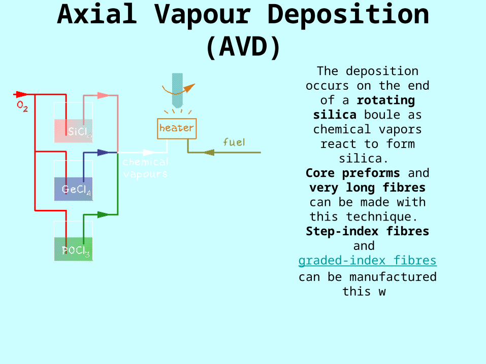
Axial Vapour Deposition (AVD)
The deposition occurs on the end of a rotating
silica boule as chemical vapors react to form silica. Core preforms and very long fibres can be made
with this technique. Step-index fibres and graded-index fibres can be manufactured this w
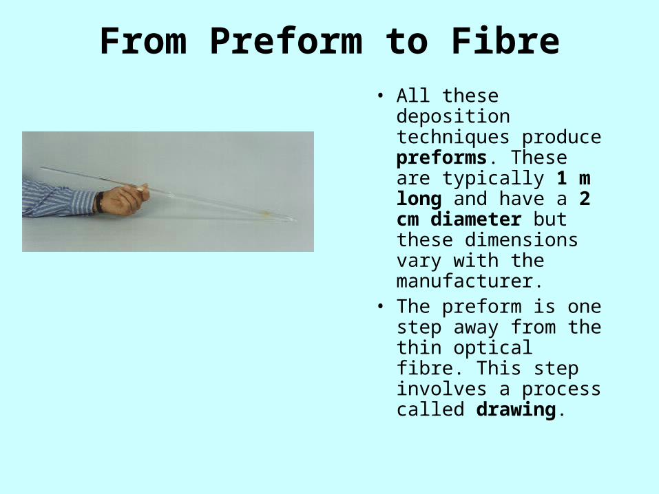
From Preform to Fibre• All these deposition
techniques produce preforms. These are typically 1 m long and have a 2 cm diameter but these dimensions vary with the manufacturer.
• The preform is one step away from the thin optical fibre. This step involves a process called drawing.

Fibre Drawing and Spooling • During this last step
of the fabrication process, many things will happen to the fibre:
• · the fibre is drawn from the preform.
• · it is quality checked
• · it is coated for protection
• · it is stored on a spool (just like a photographic film).

• The tip of the preform is heated to about 2000°C in a furnace. As the glass softens, a thin strand of softened glass falls by gravity and cools down.
• As the fibre is drawn its diameter is constantly monitored
• A plastic coating is then applied to the fibre, before it touches any components. The coating protects the fibre from dust and moisture.
• The fibre is then wrapped around a spool.
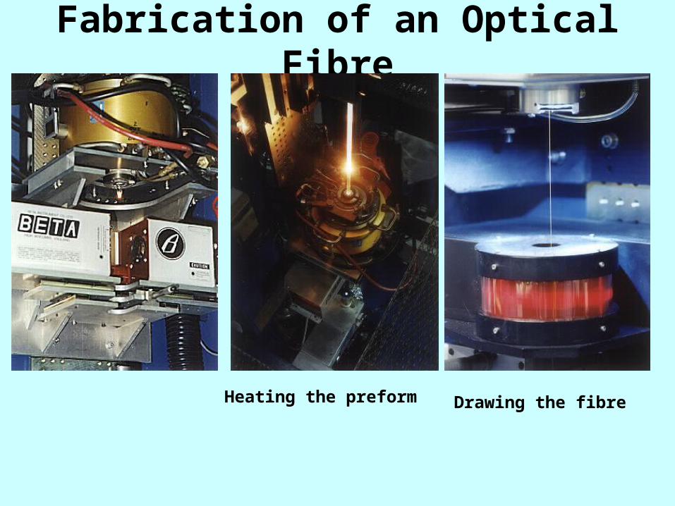
Fabrication of an Optical Fibre
Heating the preform Drawing the fibre

Piezoelectric Materials 1. When a piezoelectric material is deformed, it gives off a small but measurable electrical discharge
2. When an electrical current is passed through a piezoelectric material it experiences a significant increase in size (up to a 4% change in volume)
Most widely used as sensors in different environments
To measure fluid compositions, fluid density, fluid viscosity, or the force of an impact
Eg: Airbag sensor in modern cars- senses the force of an impact on the car and sends and electric charge deploying the airbag.

Electro-Rheostatic (ER) and Magneto-Rheostatic (MR) materials
These materials are fluids, which can experience a dramatic change in their viscosity
Can change from a thick fluid (similar to motor oil) to nearly a solid substance within the span of a millisecond when exposed to a magnetic or electric field;
the effect can be completely reversed just as quickly when the field is removed.
• THERMOPLASTICS
• THERMOSETTING PLASTICS
• ELASTOMERS
printouts shall be supplied
ABOUT• METALLIC COATINGS
• DIFFUSION COATINGS• ANODISING• POWDER COATING•
• THERMOPLASTICS• THERMOSETTING PLASTICS• ELASTOMERS printouts shall be supplied

• Self diagnostic materials Optic fibres composite
Smart compositesSmart tagged composites
• Temperature changing materials
Thermoelectric materials
• Thickness changing fluids
Magneto-Rehological fluids (MRFs)
• References Intelligent Materials
Smart materials workshop

Ferromagnetic Shape Memory Alloys (FSMA) –
• Ferromagnetic Shape Memory Alloys (FSMA) Recently discovered class of actuator material, Magnetically driven actuation (field intensity varies, about 3KG and larger) and
• large strains (around 6%). • FSMA are still in the development phase• Alloys in the Ni-Mn-Ga ternary.• FSMAs are ferromagnetic alloys which also
support the shape memory effect.

Advantages and Disadvantages of SMAs
• Bio-compatibility • Diverse Fields of Application • Good Mechanical Properties (strong, corrosion resistant)
Relatively expensive to manufacture and machine. Most SMA's have poor fatigue properties; this means that while under the same loading conditions (i.e. twisting, bending, compressing) a steel component may survive for more than one hundred times more cycles than an SMA element

• THERMOPLASTICS
• THERMOSETTING PLASTICS
• ELASTOMERS
printouts shall be supplied
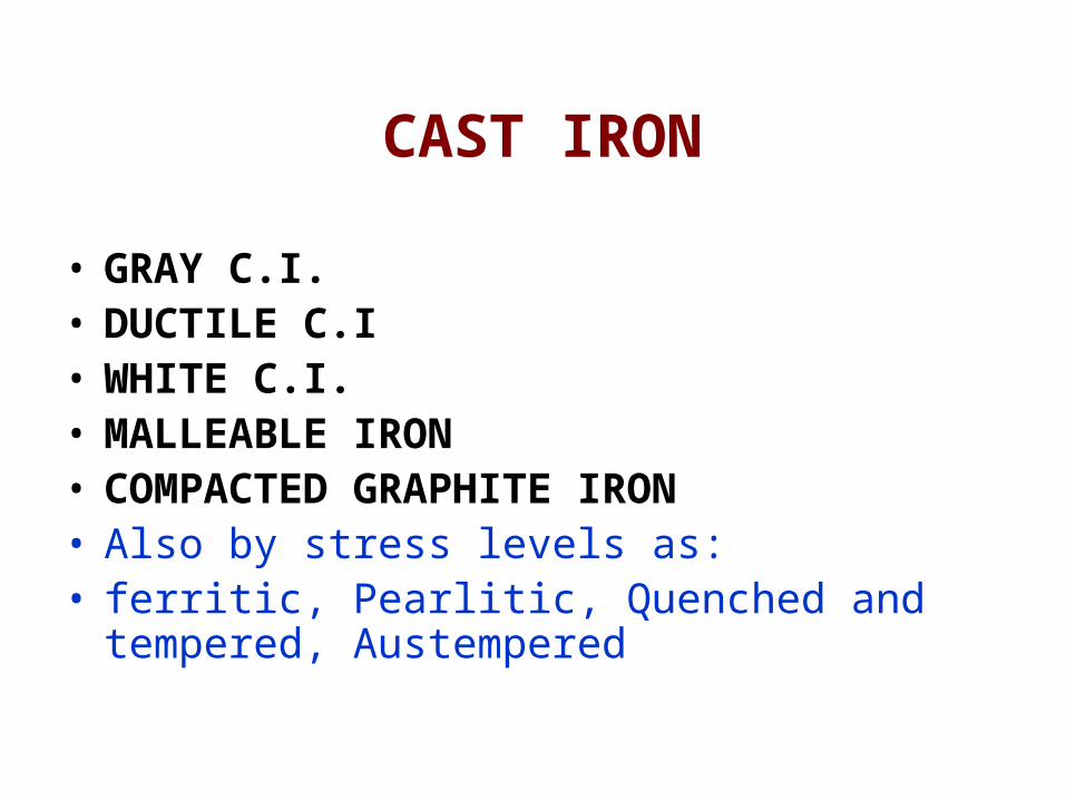
CAST IRON • GRAY C.I.• DUCTILE C.I• WHITE C.I.• MALLEABLE IRON• COMPACTED GRAPHITE IRON• Also by stress levels as: • ferritic, Pearlitic, Quenched and tempered,
Austempered

Introduction Chee 390
Unit Operations in Polymer ProcessingThermoplastic and thermoset melt processes may be broken down into:
• Preshaping• Shaping• Shape
Stabilization

Introduction Chee 390
Unit Operations in Polymer Processing• Preshaping steps:
– Solids handling and conveying: most processes usually involve feed in particulate form
– Plastication: The creation of a polymer melt from a solid feed.
– Mixing: often required to achieve uniform melt temperature or uniform composition in compounds
– Pumping : The plasticated melt must be pressurized and pumped to a shaping device
• Shaping:The polymer melt is forced through the shaping devices to create the desired shape.
The flow behavior (rheology) of polymer melts influences the design of the various shaping devices, the processing conditions and the rate at which the product can be shaped.
• Shape stabilization:– Involves the solidification of the polymer melt in the desired shape, through
heat transfer
Introduction Chee 390
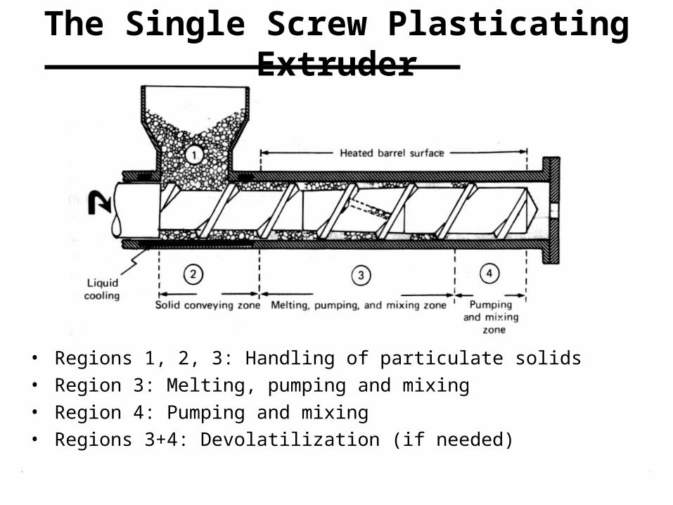
The Single Screw Plasticating Extruder
• Regions 1, 2, 3: Handling of particulate solids• Region 3: Melting, pumping and mixing• Region 4: Pumping and mixing • Regions 3+4: Devolatilization (if needed)
Introduction Chee 390
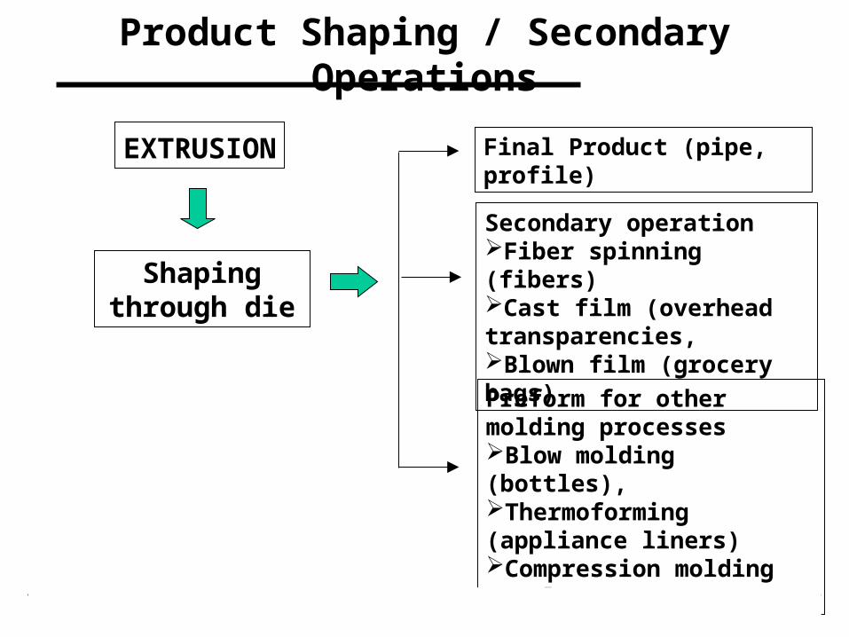
Product Shaping / Secondary Operations
EXTRUSION
Shaping through die
Final Product (pipe, profile)
Preform for other molding processesBlow molding (bottles),Thermoforming (appliance liners)Compression molding (seals)
Secondary operation Fiber spinning (fibers) Cast film (overhead transparencies, Blown film (grocery bags)

Introduction Chee 390
Annular (Tubular) DiesIn a tubular die the polymer melt exits through an annulus. These dies are used to extrude plastic pipes. The melt flows through the annular gap and solidifies at the exit in a cold water bath.

Introduction Chee 390
Profile diesProfiles are all extruded articles having cross-sectional shape that differs from that of a circle, an annulus, or a very wide and thin rectangle (such as flat film or sheet)To produce profiles for windows, doors etc. we need appropriate shaped profile dies. The cross-section of a profile die may be very complicated
Introduction Chee 390
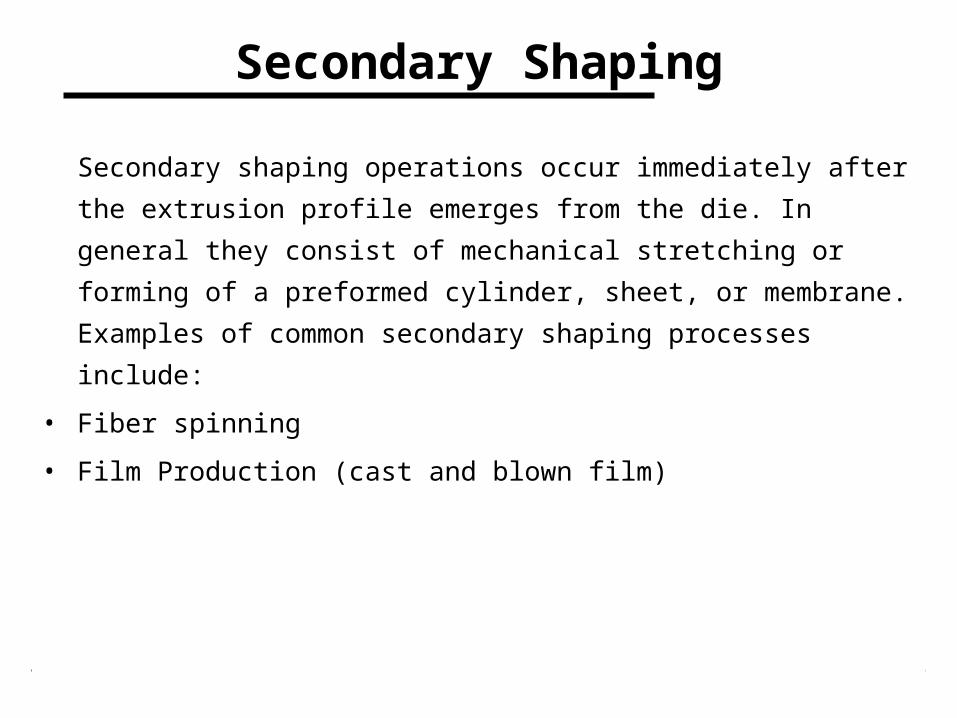
Secondary Shaping
Secondary shaping operations occur immediately after the extrusion
profile emerges from the die. In general they consist of mechanical
stretching or forming of a preformed cylinder, sheet, or membrane.
Examples of common secondary shaping processes include:
• Fiber spinning
• Film Production (cast and blown film)
Introduction Chee 390
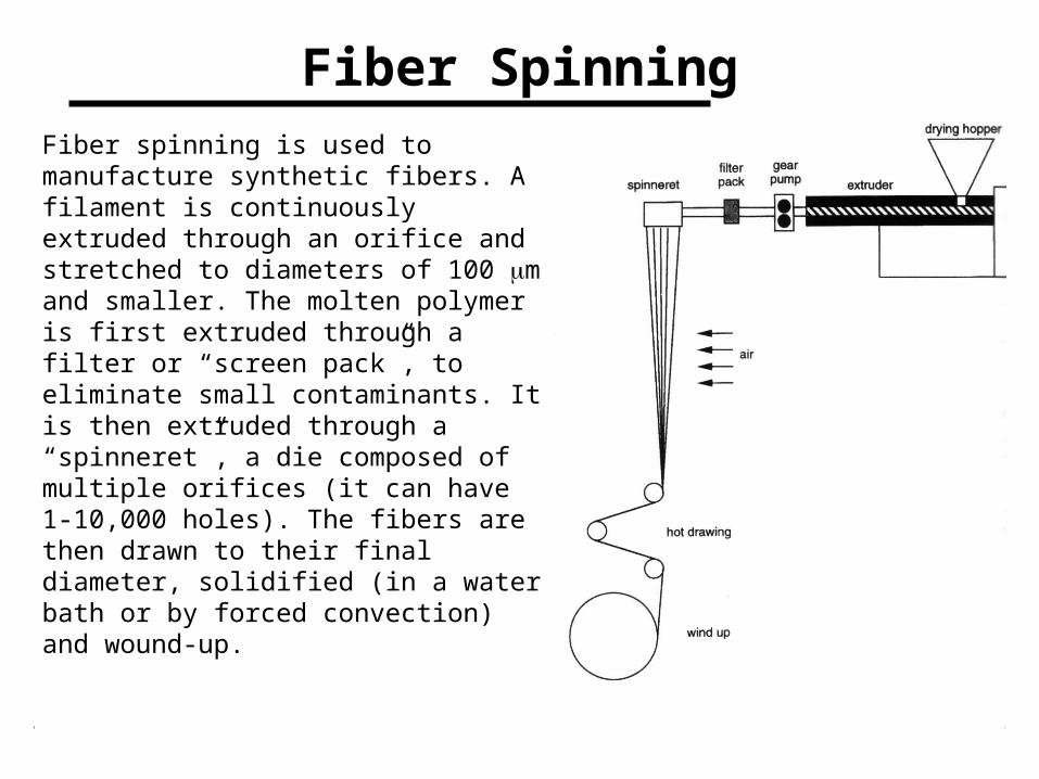
Fiber SpinningFiber spinning is used to manufacture synthetic fibers. A filament is continuously extruded through an orifice and stretched to diameters of 100 m and smaller. The molten polymer is first extruded through a filter or “screen pack”, to eliminate small contaminants. It is then extruded through a “spinneret”, a die composed of multiple orifices (it can have 1-10,000 holes). The fibers are then drawn to their final diameter, solidified (in a water bath or by forced convection) and wound-up.
Introduction Chee 390
Fiber Spinning
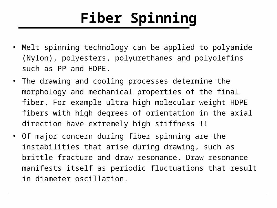
• Melt spinning technology can be applied to polyamide (Nylon),
polyesters, polyurethanes and polyolefins such as PP and HDPE.
• The drawing and cooling processes determine the morphology and
mechanical properties of the final fiber. For example ultra high
molecular weight HDPE fibers with high degrees of orientation in the
axial direction have extremely high stiffness !!
• Of major concern during fiber spinning are the instabilities that arise
during drawing, such as brittle fracture and draw resonance. Draw
resonance manifests itself as periodic fluctuations that result in
diameter oscillation.
Introduction Chee 390
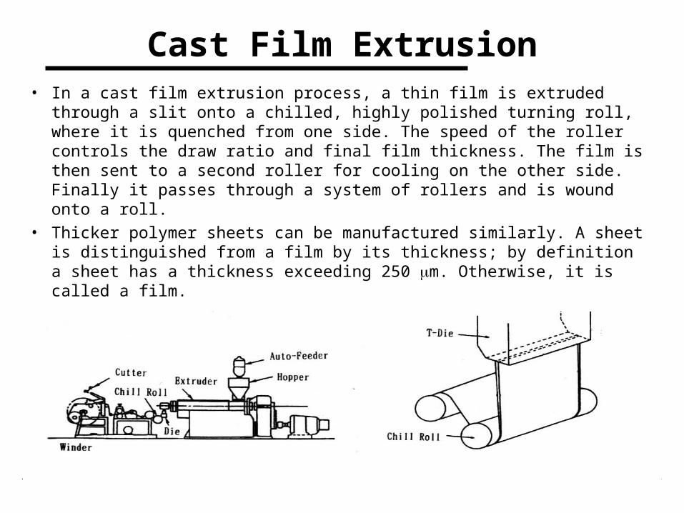
Cast Film Extrusion• In a cast film extrusion process, a thin film is extruded through a slit
onto a chilled, highly polished turning roll, where it is quenched from one side. The speed of the roller controls the draw ratio and final film thickness. The film is then sent to a second roller for cooling on the other side. Finally it passes through a system of rollers and is wound onto a roll.
• Thicker polymer sheets can be manufactured similarly. A sheet is distinguished from a film by its thickness; by definition a sheet has a thickness exceeding 250 m. Otherwise, it is called a film.
Introduction Chee 390
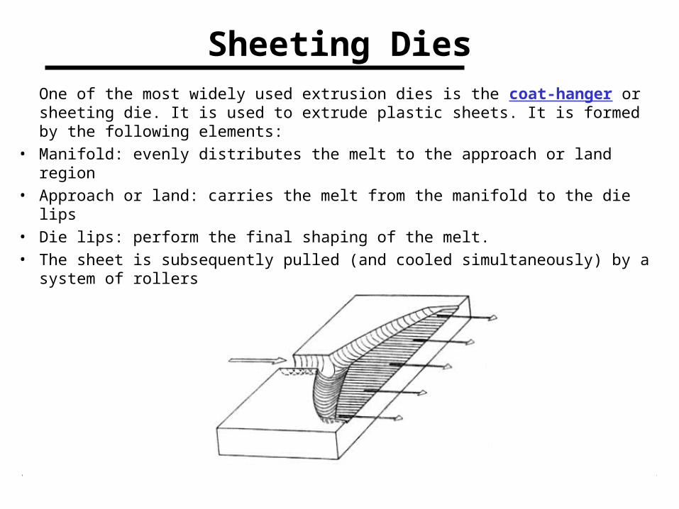
Sheeting DiesOne of the most widely used extrusion dies is the coat-hanger or sheeting die. It is used to extrude plastic sheets. It is formed by the following elements:
• Manifold: evenly distributes the melt to the approach or land region• Approach or land: carries the melt from the manifold to the die lips• Die lips: perform the final shaping of the melt.• The sheet is subsequently pulled (and cooled simultaneously) by a
system of rollers
Introduction Chee 390
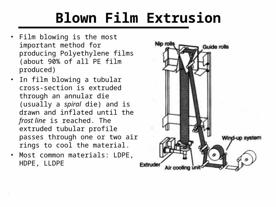
Blown Film Extrusion• Film blowing is the most important
method for producing Polyethylene films (about 90% of all PE film produced)
• In film blowing a tubular cross-section is extruded through an annular die (usually a spiral die) and is drawn and inflated until the frost line is reached. The extruded tubular profile passes through one or two air rings to cool the material.
• Most common materials: LDPE, HDPE, LLDPE

Introduction Chee 390
CoextrusionIn coextrusion two or more extruders feed a single die, in which the polymer streams are layered together to form a composite extrudate.
Introduction Chee 390
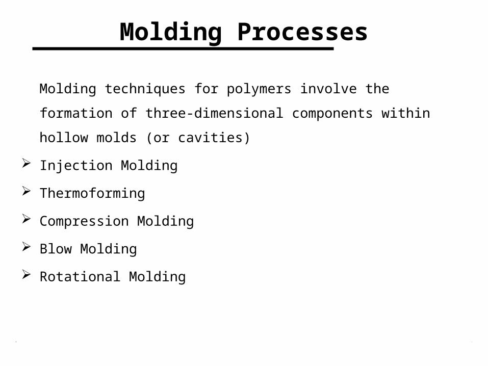
Molding Processes
Molding techniques for polymers involve the formation of three-
dimensional components within hollow molds (or cavities)
Injection Molding
Thermoforming
Compression Molding
Blow Molding
Rotational Molding
Introduction Chee 390
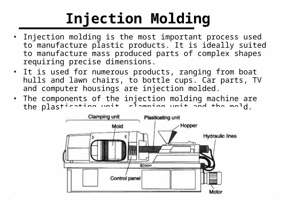
Injection Molding • Injection molding is the most important process used to manufacture
plastic products. It is ideally suited to manufacture mass produced parts of complex shapes requiring precise dimensions.
• It is used for numerous products, ranging from boat hulls and lawn chairs, to bottle cups. Car parts, TV and computer housings are injection molded.
• The components of the injection molding machine are the plasticating unit, clamping unit and the mold.
Introduction Chee 390
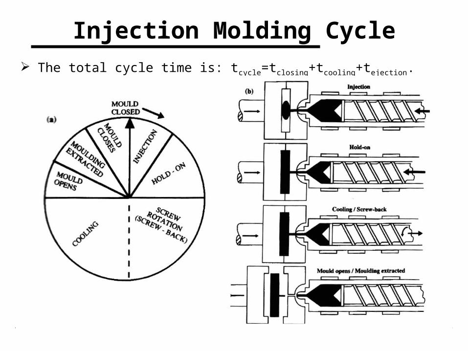
Injection Molding Cycle
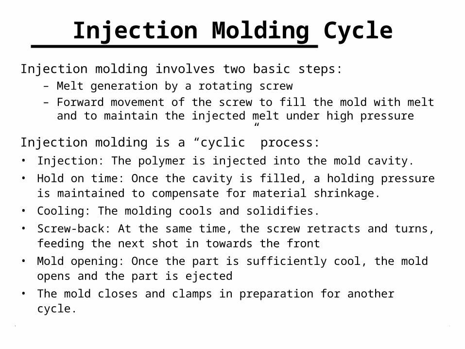
Injection molding involves two basic steps:– Melt generation by a rotating screw
– Forward movement of the screw to fill the mold with melt and to maintain the injected melt under high pressure
Injection molding is a “cyclic” process:• Injection: The polymer is injected into the mold cavity.
• Hold on time: Once the cavity is filled, a holding pressure is maintained to compensate for material shrinkage.
• Cooling: The molding cools and solidifies.
• Screw-back: At the same time, the screw retracts and turns, feeding the next shot in towards the front
• Mold opening: Once the part is sufficiently cool, the mold opens and the part is ejected
• The mold closes and clamps in preparation for another cycle.
Introduction Chee 390
Injection Molding Cycle
The total cycle time is: tcycle=tclosing+tcooling+tejection.
Introduction Chee 390
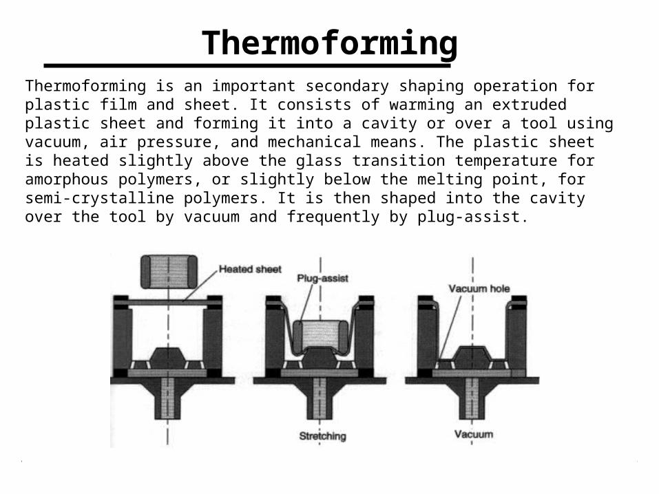
ThermoformingThermoforming is an important secondary shaping operation for plastic film and sheet. It consists of warming an extruded plastic sheet and forming it into a cavity or over a tool using vacuum, air pressure, and mechanical means. The plastic sheet is heated slightly above the glass transition temperature for amorphous polymers, or slightly below the melting point, for semi-crystalline polymers. It is then shaped into the cavity over the tool by vacuum and frequently by plug-assist.

Introduction Chee 390
Thermoforming
• Thermoforming is used to manufacture refrigerator liners, shower stalls, bathtubs and various automotive parts.
• Amorphous materials are preferred, because they have a wide rubbery temperature range above the glass transition temperature. At these temperatures, the polymer is easily shaped, but still has enough “melt strength” to hold the heated sheet without sagging. Temperatures about 20-100°C above Tg are used.
• Most common materials are Polystyrene (PS), Acrylonitrile-Butadiene-Styrene (ABS), PVC, PMMA and Polycarbonate (PC)
Introduction Chee 390
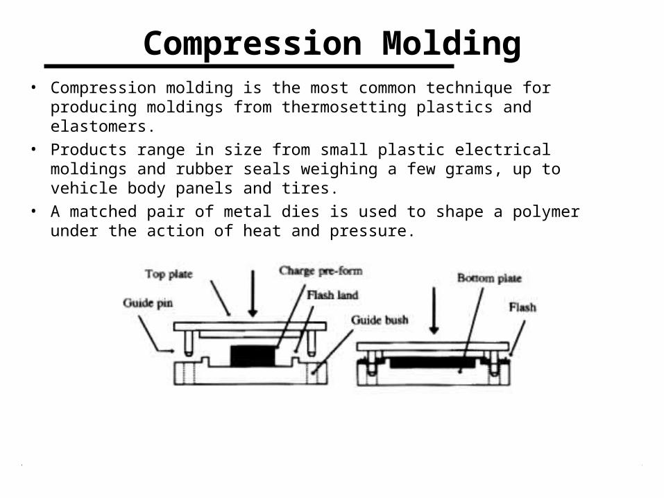
Compression Molding• Compression molding is the most common technique for producing
moldings from thermosetting plastics and elastomers.• Products range in size from small plastic electrical moldings and
rubber seals weighing a few grams, up to vehicle body panels and tires.
• A matched pair of metal dies is used to shape a polymer under the action of heat and pressure.
Introduction Chee 390
Blow MoldingBlow molding produces hollow articles that do not require a homogeneous thickness distribution. HDPE, LDPE, PE, PET and PVC are the most common materials used for blow molding. There are three important blow molding techniques:
• Extrusion blow molding• Injection blow molding• Stretch-blow processes
They involve the following stages:– A tubular preform is produced via extrusion or injection molding
– The temperature controlled perform is transferred into a cooled split-mould
– The preform is sealed and inflated to take up the internal contours of the mould
– The molding is allowed to cool and solidify to shape, whilst still under internal pressure
– The pressure is vented, the mold opened and the molding ejected.
Introduction Chee 390
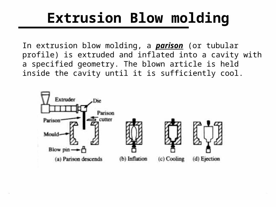
Extrusion Blow molding
In extrusion blow molding, a parison (or tubular profile) is extruded and inflated into a cavity with a specified geometry. The blown article is held inside the cavity until it is sufficiently cool.
Introduction Chee 390
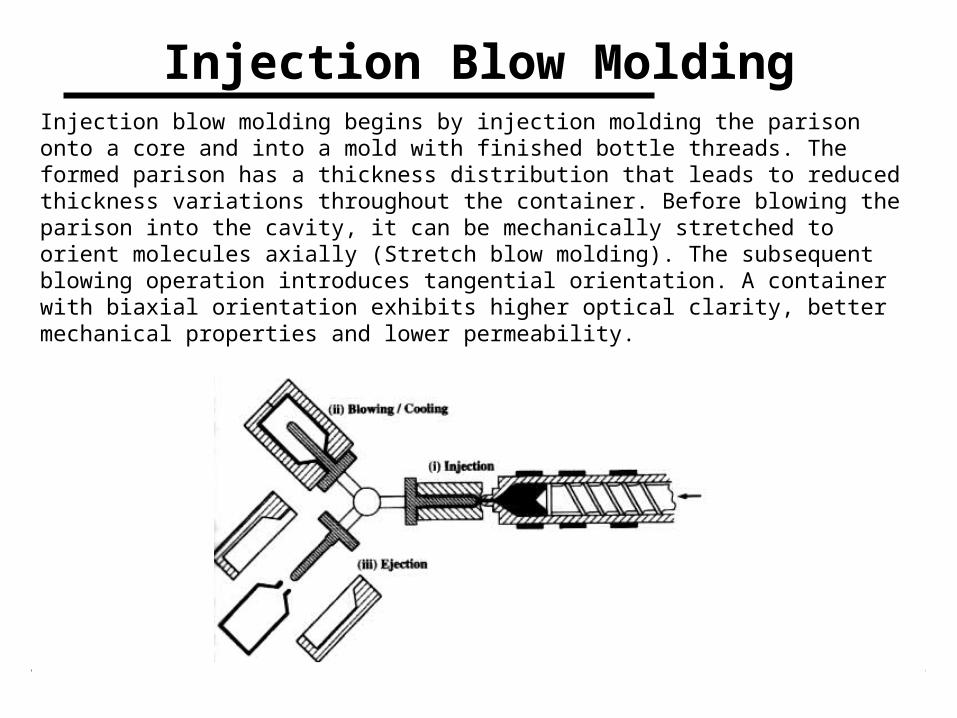
Injection Blow MoldingInjection blow molding begins by injection molding the parison onto a core and into a mold with finished bottle threads. The formed parison has a thickness distribution that leads to reduced thickness variations throughout the container. Before blowing the parison into the cavity, it can be mechanically stretched to orient molecules axially (Stretch blow molding). The subsequent blowing operation introduces tangential orientation. A container with biaxial orientation exhibits higher optical clarity, better mechanical properties and lower permeability.