Embed Size (px)
Citation preview
Contents lists available at ScienceDirect
Acta Astronautica
Acta Astronautica 99 (2014) 215–230
http://d0094-57
n CorrE-m
mleok@nhm@u
journal homepage: www.elsevier.com/locate/actaastro
High-fidelity numerical simulation of complex dynamicsof tethered spacecraft
Taeyoung Lee a,n, Melvin Leok b, N. Harris McClamroch c
a Mechanical and Aerospace Engineering, George Washington University, Washington, DC 20052, United Statesb Mathematics, University of California at San Diego, La Jolla, CA 92093, United Statesc Aerospace Engineering, University of Michigan, Ann Arbor, MI 48109, United States
a r t i c l e i n f o
Article history:Received 25 January 2013Received in revised form7 February 2014Accepted 21 February 2014Available online 12 March 2014
Keywords:Geometric numerical integratorTethered spacecraftNumerical simulation
x.doi.org/10.1016/j.actaastro.2014.02.02165/& 2014 IAA. Published by Elsevier Ltd. A
esponding author.ail addresses: [email protected] (T. Lee),math.ucsd.edu (M. Leok),mich.edu (N. Harris McClamroch).
a b s t r a c t
This paper presents an analytical model and a geometric numerical integrator for atethered spacecraft model that is composed of two rigid bodies connected by an elastictether. This high-fidelity model includes important dynamic characteristics of tetheredspacecraft in orbit, namely the nonlinear coupling among tether deformations, rigid bodyrotational dynamics, a reeling mechanism, and orbital dynamics. A geometric numericalintegrator, referred to as a Lie group variational integrator, is developed to numericallypreserve the Hamiltonian structure of the presented model and its Lie group configurationmanifold. This approach preserves the geometry of the configurations, and leads toaccurate and efficient algorithms that have guaranteed accuracy properties that makethem suitable for many dynamic simulations, especially over long simulation times. Theseanalytical and computational models provide a reliable benchmark for testing the validityand applicability of the many simplified models in the existing literature, which havehitherto been used without careful verification that the simplifying assumptionsemployed are valid in physically realistic parameter regimes. We present numericalsimulations which illustrate the important qualitative differences in the tethered space-craft dynamics when the high-fidelity model is employed, as compared to models withadditional simplifying assumptions.
& 2014 IAA. Published by Elsevier Ltd. All rights reserved.
1. Introduction
Tethered spacecraft are composed of multiple satellitesin orbit, that are connected by a thin, long cable. Numerousinnovative space missions have been envisaged, such aspropulsion by momentum exchange, extracting energyfrom the Earth's magnetic field, satellite de-orbiting, orMars exploration [1–3], and several actual missions, such
ll rights reserved.
as TSS, SEDS, or YES2 have been conducted by NASA andESA [1,4].
The dynamics of tethered spacecraft involves nonlinearcoupling effects between several dynamic modes evolvingon multiple length and time scales. For example, a fullscale tethered spacecraft may employ tethers with lengthsup to a 100 km, while recently proposed nano-tetheredspacecraft may employ short tethers of several meters inlength. This is in stark contrast to the orbital radius oftethered spacecraft, which is several thousand kilometers.The natural frequency of the tether is much higher thanthe frequency of the rotational attitude dynamics or theorbital period of the spacecraft. The rotational dynamicsof spacecraft is nontrivially coupled to the tension of the
T. Lee et al. / Acta Astronautica 99 (2014) 215–230216
tether, which is affected by the reeling mechanism andorbital maneuver. Therefore, it is important to accuratelymodel tether dynamics, attitude dynamics of the space-craft, reeling mechanisms, gravitational force and theinteractions between them.
Several analytic and numerical models have beendeveloped for tethered spacecraft. However, due to thecomplexities of tethered spacecraft, it is common practiceto use simplified models. Two point masses connected by arigid tether were considered in [5]. The dynamics of amassless, flexible tether was included in [6]. Transversevibrations of two point masses connected by a flexible, butinextensible, tether were studied in [7]. The attitudedynamics of the payload satellite is considered in [8] inorder to provide insights into the dynamics anomalies inthe actual flight data of the OEDIPUS-A tethered rocketpayload. However, this did not entail a fully coupledsimulation, rather the paper addressed the response ofthe payload to prescribed disturbances in the tethertension, as opposed to explicitly including the dynamiccoupling between the central satellite and the tether.
Vibration mode analysis is provided in [9–11], but asmall vibrational amplitude assumption is imposed on thecontrolled tether [9]; the effect of an appendage extendingat a prescribed rate is studied for a single spacecraft in[10]; and a linearized model of a spacecraft model con-nected to a fixed-length tether is studied in [11]. Thesesimplified models allow for rigorous mathematical analy-sis, but they may fail to accurately predict the behavior ofactual tethered spacecrafts, particularly since tetheredspacecraft operations are typically based on weak non-linear effects that act over a long time period. Recentnumerical studies consider more sophisticated tetheredspacecraft models including a varying tether length. But, inthese advanced models, rigid body dynamics is ignored[12,13], and the reeling mechanism is neglected [12,14].
We have been motivated by these previous models toconstruct a high-fidelity mathematical and numericalmodel for elucidating the dynamics of tethered spacecraftwhere the tether is long relative to the dimensions of thespacecraft. This high-fidelity model can serve as a math-ematical and computational testbed for exploring theextent to which nonlinear coupling between the variousdynamic modes result in interesting and unforeseen phe-nomena that could serve as the basis for novel missiondesigns. While simplified models are desirable because oftheir computational efficiency and the ease with whichthey can be analyzed, as well as their applicability for real-time model predictive control in embedded applications,they typically have limited regimes of applicability inparameter space. Our high-fidelity model provides a reli-able benchmark for determining the range of validity forthe simplified models that have currently been studied, inan effort to determine which, if any, of the simplifyingassumptions used in other models provide a valid simpli-fied model in the parameter regimes for realistic tetheredsatellite missions.
For such applications, the primary deployment mechan-ism is through a reeling mechanism, and a careful model ofthe reeling mechanism is essential to resolving the coupledinteractions among tether, reeling, and rotational dynamics.
In particular, this allows us to resolve the elastic wavespropagating along the tether, the dynamics of the reelingmechanism, rotational dynamics of the satellites, as well asthe external forces arising from solar wind, atmosphericdrag or electrodynamic effects. The long aspect ratio of thetether also means that there is effectively no resistance tobending and torsion in the tether, and the main effect islongitudinal elastic deformation along the tether. Whilebending can easily be incorporated by including an addi-tional term in the potential energy, torsion will require us toconsider a larger configuration space for the model. Theseassumptions and observations motivate the modelingchoices that have been made in our model.
More precisely, the goal of this paper is to develop ahigh-fidelity analytical model and numerical simulationsfor tethered spacecraft. This is an extension of preliminarywork that studies a string pendulum model with a reelingmechanism [15,16]. The first part of this paper provides arealistic and accurate analytical tethered spacecraft modelincluding tether deformations, attitude dynamics of rigidbodies, and a reeling mechanism. We show that thegoverning equations of motion can be developed usingHamilton's principle.
The second part of this paper deals with a geometricnumerical integrator for tethered spacecraft. Geometricnumerical integration is concerned with developingnumerical integrators that preserve the geometric featuresof a system, such as dynamical and geometric invariants,symmetries, and the structure of nonlinear configurationspaces [17]. Because these geometric invariants play animportant role in the long-time qualitative and structuralproperties of a system, geometric structure-preservingintegrators yield computational trajectories that moreaccurately reflect the qualitative and statistical propertiesof the system. These methods also exhibit more robustenergy properties, and avoid the artificial numerical dis-sipation introduced by conventional integrators. A geo-metric numerical integrator, referred to as a Lie groupvariational integrator, has been developed for a Hamilto-nian system on an arbitrary Lie group in [18]. The pro-posed method is competitive from the point of view ofcomputational efficiency. Even though the methodrequires a nonlinear solve, this can be efficiently imple-mented using a fixed-point iteration, and the method onlyrequires one force evaluation per time-step.
A tethered spacecraft is a Hamiltonian system, and itsconfiguration manifold is expressed as the product of theLie groups SOð3Þ, SEð3Þ, and the space of connected curvesegments on R3. This paper develops a Lie group varia-tional integrator for tethered spacecraft based on theresults presented in [18]. The proposed geometric numer-ical integrator preserves symplecticity and momentummaps, and exhibits desirable energy conservation proper-ties. It also respects the Lie group structure of the config-uration manifold, and avoids the singularities andcomputational complexities associated with the use oflocal coordinates. It can be used to study non-local, largeamplitude and deformation maneuvers of tethered space-craft accurately over a long time period. This is in contrastto conventional approaches where small deformations aresuperimposed to a simplified, rigid tethered spacecraft
T. Lee et al. / Acta Astronautica 99 (2014) 215–230 217
model and the important coupling effects between variousdynamic modes are ignored.
The main contributions of this paper are summarizedas follows: (i) a realistic mathematical model for tetheredspacecraft that characterize the nonlinear couplingbetween the translation dynamics and the rotationaldynamics of spacecraft, the translation and the deforma-tion of the tether, and the reeling mechanism, (ii) unifyingvariational framework to develop equations of motion, (iii)high-fidelity numerical model to compute complex dynamicsof tethered spacecraft accurately.
This paper is organized as follows. A tethered space-craft model is described in Section 2. An analytical modeland a Lie group variational integrator are developed inSections 3 and 4, respectively, followed by numericalexamples in Section 5.
2. Tethered spacecraft
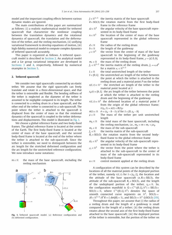
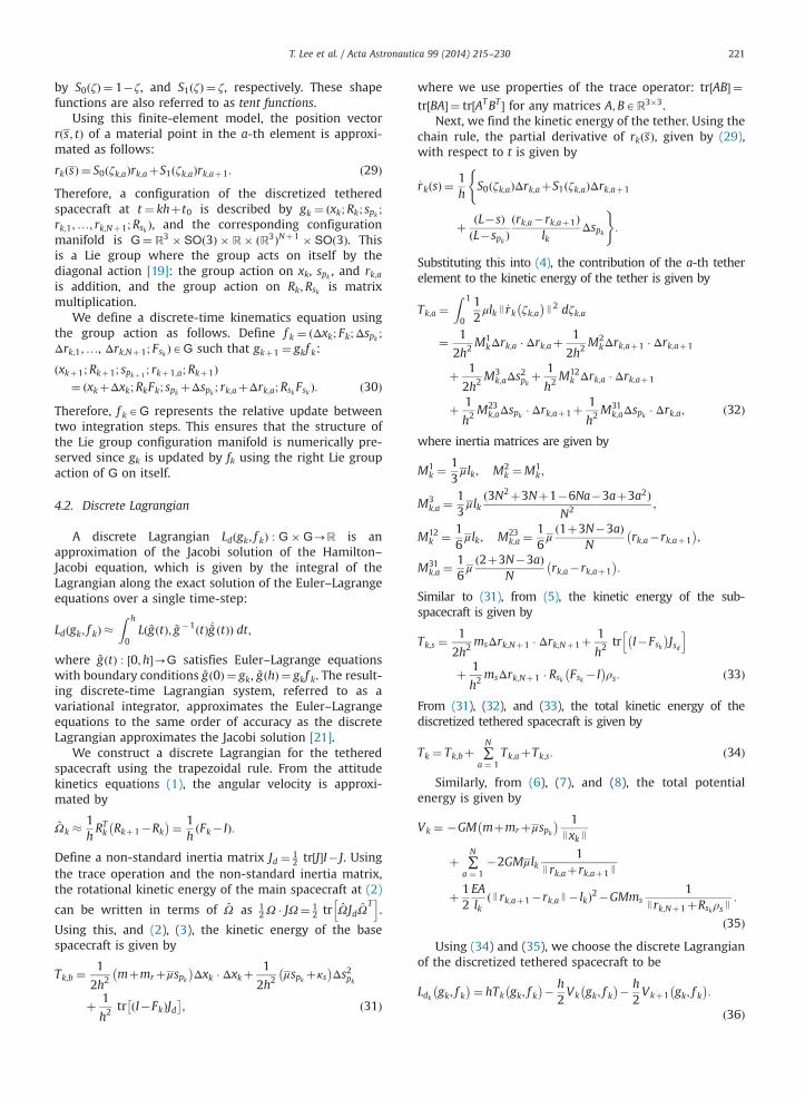
We consider two rigid spacecrafts connected by an elastictether. We assume that the rigid spacecrafts can freelytranslate and rotate in a three-dimensional space, and thatthe tether is extensible and flexible. The bending stiffness ofthe tether is neglected as the diameter of the tether isassumed to be negligible compared to its length. The tetheris connected to a reeling drum in a base spacecraft, and theother end of the tether is connected to a sub-spacecraft. Thepoint where the tether is attached to the spacecraft isdisplaced from the center of mass so that the rotationaldynamics of the spacecraft is coupled to the tether deforma-tions and displacements. This model is illustrated in Fig. 1.
We choose a global reference frame and two body-fixedframes. The global reference frame is located at the centerof the Earth. The first body-fixed frame is located at thecenter of mass of the base spacecraft, and the secondbody-fixed frame is located at the end of the tether wherethe tether is attached to the sub-spacecraft. Since thetether is extensible, we need to distinguish between thearc length for the stretched deformed configuration andthe arc length for the unstretched reference configuration.We now introduce some notations:
mAR the mass of the base spacecraft, excluding thereeling mechanism
Fig. 1. Tethered spacecraft model. (a) Reference configuration and(b) deformed configuration.
JAR3�3 the inertia matrix of the base spacecraftRASOð3Þ the rotation matrix from the first body-fixed
frame to the reference frameΩAR3 the angular velocity of the base spacecraft repre-
sented in its body-fixed framexAR3 the location of the center of mass of the base
spacecraft represented in the global referenceframe
dAR the radius of the reeling drumbAR the length of the guidewayρAR3 the vector from the center of mass of the base
spacecraft to the beginning of the guidewayrepresented in its body-fixed frame, ρ¼ ½d;0; b�.
mrAR the mass of the reeling drumJrAR3�3 the inertia matrix of the reeling drum, Jr ¼ κrd
2
for a matrix κrAR3�3
LAR the total unstretched length of the tethersA ½0; L� the unstretched arc length of the tether between
the point at which the tether is attached to thereeling drum and a material point P on the tether
sðs; tÞARþ the stretched arc length of the tether to thematerial point located at s
spðtÞA ½b; L� the arc length of the tether between the pointat which the tether is attached to the reelingdrum and the beginning of the guideway
rðs; tÞAR3 the deformed location of a material point Pfrom the origin of the global reference frame;rðsp; tÞ ¼ xðtÞþRðtÞρ
θðsÞAR θ¼ ðsp�b�sÞ=d for sA ½0; sp�b�μAR The mass of the tether per unit unstretched
lengthmbAR the total mass of the base spacecraft, including
the reeling mechanism, i.e., mb ¼mþmrþμspmsAR the mass of the sub-spacecraftJsAR the inertia matrix of the sub-spacecraftRsASOð3Þ the rotation matrix from the second body-
fixed frame to the global reference frameΩsAR3 the angular velocity of the sub-spacecraft repre-
sented in its body-fixed frameρsAR3 the vector from the point where the tether is
attached to the sub-spacecraft to the center ofmass of the sub-spacecraft represented in itsbody-fixed frame
uAR control moment applied at the reeling drum
A configuration of this system can be described by thelocations of all the material points of the deployed portionof the tether, namely rðs; tÞ for sA ½sp; L�, the location andthe attitude of the base spacecraft ðx;RÞASEð3Þ, theattitude of the sub-spacecraft RsASOð3Þ, and the lengthof the undeployed portion of the tether, spAR. So,the configuration manifold is G¼ C1ð½0; L�;R3Þ � SEð3Þ�SOð3Þ � R, where C1ð½0; L�;R3Þ denotes the space ofsmooth connected curve segments on R3, SOð3Þ ¼fRAR3�3j RTR¼ I;det½R� ¼ 1g, and SEð3Þ ¼R3 ⓢSOð3Þ [19].
Throughout this paper, we assume that (i) the radius ofa reeling drum and the length of a guideway is smallcompared to the length of a tether; (ii) the reeling drumrotates about the second axis of the first body-fixed frameattached to the base spacecraft; (iii) the deployed portionof the tether is extensible, but the portion of the tether on
T. Lee et al. / Acta Astronautica 99 (2014) 215–230218
the reel and the guideway inside the base spacecraft isinextensible; (iv) the gravity is uniform over the basespacecraft and the sub-spacecraft.
The attitude kinematics equation of the base spacecraftand the sub-spacecraft is given by
_R ¼ RΩ; _Rs ¼ RΩs; ð1Þwhere the hat map � : R3-soð3Þ is defined by the condi-tion that xy¼ x� y for any x; yAR3 [18]. The inverse of thehat map is denoted by the vee map: ð�Þ4 : soð3Þ-R3.
3. Continuous-time analytical model
In this section, we develop continuous-time equationsof motion for a tethered spacecraft using Hamilton'svariational principle.
3.1. Lagrangian
Kinetic energy: The kinetic energy is composed of thekinetic energy of the base rigid body Tb1 , the kineticenergy of the reeling mechanism Tb2 , the kinetic energyof the deployed portion of the tether Tt, and the kineticenergy of the sub-spacecraft Ts. The kinetic energy of thebase rigid body is given by
Tb1 ¼ 12m _x � _xþ1
2Ω � JΩ: ð2ÞThe kinetic energy of the reeling mechanism is given by
Tb2 ¼ 12 mrþμsp� �
_x � _xþ12 μsp _s
2pþ1
2 κ2 _s2p; ð3Þ
where κ2 ¼ e2 � κre2. This is obtained by integrating theinfinitesimal kinetic energy of the material points on theundeployed portion of tether, and ignoring higher-orderterms of b, d due to the assumption that the radius ofreeling drum d and the length of the guideway b is muchless than the length of the tether.
Let _rðs; tÞ be the partial derivative of rðs; tÞ with respectto t. The kinetic energy of the deployed portion of thetether is given by
Tt ¼Z L
sp
12μ _r sð Þ � _r sð Þ ds: ð4Þ
Let ~ρAR3 be the vector from the end of the tether to amass element of the sub-spacecraft represented withrespect to its body-fixed frame. The location of the masselement in the global reference frame is given by rðLÞþRs ~ρ.Then, the kinetic energy of the sub-spacecraft is given by
Ts ¼ZBs
12J _r Lð ÞþRsΩs ~ρ J2 dm
¼ 12ms _r Lð Þ � _r Lð Þþms _r Lð Þ � RsΩsρsþ
12Ωs � JsΩs: ð5Þ
Here, we use the fact thatRBs~ρ dm¼ ρc, and Js ¼
�RBsρ2s dm. The total kinetic energy is given by
T ¼ Tb1 þTb2 þTtþTs.Potential energy: From the assumption that the reeling
drum is small relative to the length of the tether, thegravitational potential of the base spacecraft and the
reeling mechanism can be approximated as follows:
Vb ¼ � mþmrþμsp� � GM
JxJ¼ �mb
GMJxJ
; ð6Þ
where the gravitational constant and the mass of the Earthare denoted by G and M, respectively.
The strain of the tether at a material point located atrðsÞ is given by
ϵ¼ limΔs-0
ΔsðsÞ�ΔsΔs
¼ s0 sð Þ�1;
where ðÞ0 denotes the partial derivative with respect to s.The tangent vector at the material point is given by
et ¼∂rðsÞ∂s
¼ ∂rðsÞ∂s
∂s∂sðsÞ ¼
r0ðsÞs0ðsÞ:
Since this tangent vector has unit length, we haves0ðsÞ ¼ ‖r0ðsÞ‖. Therefore, the strain can be written asϵ¼ ‖r0ðsÞ‖�1. Using this, the elastic potential and thegravitational potential of the deployed portion of thetether are given by
Vt ¼ 12
Z L
spEAð‖r0ðsÞ‖�1Þ2 ds�
Z L
spμ
GMJrðsÞJ ds;
ð7Þ
where E and A denote Young's modulus and the sectionalarea of the tether, respectively.
The location of the center of mass of the sub-spacecraftis rðLÞþRsρs in the global reference frame. Since we assumethat the gravity is uniform over each spacecraft body, thegravitational potential energy of the sub-spacecraft isgiven by
Vs ¼ �msGM
JrðLÞþRsρs J: ð8Þ
From (2)–(8), the Lagrangian of the tethered spacecraftis given by
L¼ ðTb1 þTb2 �VbÞþðTt�VtÞþðTs�VsÞ ð9Þ
L¼ LbþLtþLs: ð10Þ
3.2. Euler–Lagrange equations
Let the action integral be
G¼Z tf
t0LbþLtþLs dt ¼GbþGtþGs: ð11Þ
According to the Lagrange–d'Alembert principle, the var-iation of the action integral is equal to the negative of thevirtual work for fixed boundary conditions, which yieldsthe forced Euler–Lagrange equations. For the given teth-ered spacecraft model, there are three aspects that requirecareful consideration: (i) the rotation matrices R;Rs thatrepresents the attitudes lie in the nonlinear Lie groupSOð3Þ; (ii) the domain of the integral depends on thevariable sp(t) at (4); (iii) since the tether is assumed to beinextensible in the guideway, and it is extensible outsize ofthe guideway, there exists a discontinuity in strain at thebeginning of the guideway.
Variation of Gb: The attitudes of spacecraft are repre-sented by the rotation matrix R;RsASOð3Þ. Therefore, the
T. Lee et al. / Acta Astronautica 99 (2014) 215–230 219
variation of the rotation matrix should be consistent withthe geometry of the special orthogonal group. In [18], it isexpressed in terms of the exponential map as
δR¼ ddϵ
����ϵ ¼ 0
Rϵ ¼ ddϵ
����ϵ ¼ 0
R exp ϵη ¼ Rη; ð12Þ
for ηAR3. The key idea is expressing the variation of a Liegroup element in terms of a Lie algebra element. This isdesirable since the Lie algebra soð3Þ of the special ortho-gonal group, represented by 3�3 skew-symmetricmatrices, is isomorphic as a Lie algebra to R3. As a result,the variation of the three-dimensional rotation matrix R isexpressed in terms of a vector ηAR3. We can directly showthat (12) satisfies δðRTRÞ ¼ δRTRþRTδR¼ � ηþ η ¼ 0. Thecorresponding variation of the angular velocity is obtainedfrom the kinematics equation (1):
δΩ ¼ ddϵ
����ϵ ¼ 0
ðRϵÞT _Rϵ ¼ ð_ηþΩ� ηÞ4 : ð13Þ
Using (12) and (13), and integration by parts, the variationof Gb is given by
δGb ¼Z tf
t0�mb €x�μ _sp _x�GMmb
x
JxJ3
� �� δx
þ � μspþκ2� �
€spþ12 μ _x � _x� _s2pþ2
GMJxJ
� �� �δsp
�fJ _ΩþΩJΩg � η dt: ð14Þ
Variation of Gt: The action integral for tether namely Gt
is expressed as a double integral on ðt; sÞA ½t0; tf � � ½spðtÞ; L�,given by
Gt ¼Z tf
t0
Z L
spðtÞ
12μ _r sð Þ � _r sð Þ� 1
2EAð‖r0ðsÞ‖�1Þ2þμ
GM‖rðsÞ‖ ds dt:
Thus, its variation should take account of the sp(t) varia-tion:
δGt ¼Z tf
t0
Z L
spμ _r sð Þ � δ_r sð Þ�EA
‖r0ðsÞ‖�1‖r0ðsÞ‖r0 sð Þ � δr0 sð Þ
�μGMrðsÞ
JrðsÞJ3� δr sð Þ ds dt�
Z tf
t0
12μ _r sþp
� _r sþp
:
�
� 12EAð‖r0ðsþp Þ‖�1Þ2þμ
GMJrðspÞJ
�δsp dt; ð15Þ
where _rðsþp Þ represents the material velocity at the outsideof the guideway.
Now, we focus on the first term of (15). We cannotapply integration by parts with respect to s, since the orderof the integrals cannot be interchanged as sp(t) depends ont. Instead, we use Green's theorem [15]:
∮C _r sð Þ � δr sð Þ ds ¼Z tf
t0
Z L
sp
ddt
_r sð Þ � δr sð Þð Þ ds dt; ð16Þ
where ∮C represents the counterclockwise line integral onthe boundary C of the region ½t0; tf � � ½spðtÞ; L�. The bound-ary C is composed of four lines: ðt ¼ t0; sA ½spðt0Þ; L�Þ,ðt ¼ tf ; sA ½spðtf Þ; L�Þ, ðtA ½t0; tf �; s ¼ spðtÞÞ, and ðtA ½t0; tf �;s ¼ LÞ. For the first two lines, δrðsÞ ¼ 0 since t ¼ t0; tf . Forthe last line, ds ¼ 0 since s is fixed. Thus, parameterizing
the third line by t, we obtain
∮C _rðsÞ � δrðsÞ ds ¼Z tf
t0
_rðspðtÞÞ � δrðspðtÞÞ_spðtÞ dt:
Substituting this into (16) and rearranging, we obtainZ tf
t0
Z L
sp
_rðsÞ � δ_rðsÞ ds dt
¼Z tf
t0
Z L
sp� €rðsÞ � δrðsÞ dsþ _rðspÞ � δrðspÞ_sp
" #dt: ð17Þ
Substituting (17) into (15), and using integration by parts,the variation of Gt can be written as
δGt ¼Z tf
t0
Z L
sp�μ €r sð ÞþF 0 sð Þ�μGM
rðsÞJrðsÞJ3
( )� δr sð Þ ds dt
þZ tf
t0� 1
2μ _r sþp
� _r sþp
þ12 EAð‖r0ðsþp Þ‖�1Þ2
�
�μGM
JrðspÞJ
�δsp
þμ _rðsþp Þ � δrðsþp Þ_sp�FðLÞ � δrðLÞþFðspÞ � δrðsþp Þ dt;ð18Þ
where FðsÞ ¼ EAðð‖r0ðsÞ‖�1Þ=‖r0ðsÞ‖Þr0ðsÞ.This is further simplified as follows. Let rp ¼ rðspðtÞ; tÞ be
the location of the beginning of the guideway. Since it canbe written as rp ¼ xþRρ, we have δrp ¼ δrðsþp Þþr0ðsþp Þδsp ¼δxþRηρ. Thus,
δrðsþp Þ ¼ �r0ðsþp Þδspþδx�Rρη:
Similarly, we obtain
_rðsþp Þ ¼ �r0ðsþp Þ_spþ _x�RρΩ:
Substituting these into (18), the variation of Gt isexpressed in terms of δrðsÞ, δsp, δx, η, and δrðLÞ.
Variation of Gs: Similar to (14), the variation of Gs isgiven by
δGs ¼Z tf
t0
(�ms €rðLÞ�msRsΩ
2s ρs�msRs _Ω sρs
�GMmsrðLÞþRsρs
JrðLÞþRsρs J3
)� r Lð Þþ
(� J _Ωs�msρsR
Ts €rðLÞ
�ΩsJΩs�GMmsrðLÞþRsρs
JrðLÞþRsρs J3
)� ηs dt: ð19Þ
In short, the variation of the action integral is given by(14), (18), and (19).
Variational principle with discontinuity: Let rðs�p Þ, andrðsþp Þ be the material point of the tether just inside theguideway, and the material point just outside the guide-way, respectively. Since the tether is inextensible insidethe guideway, Jr0ðs�p ÞJ ¼ 1. Since the tether is extensibleoutside the guideway, Jr0ðsþp ÞJ ¼ 1þϵþ , where ϵþ repre-sents the strain of the tether just outside the guideway.Due to this discontinuity, the speed of the tether changesinstantaneously by the amount ϵþ j_spj at the guideway.
As a result, the variation of the action integral is notequal to the negative of the virtual work done by theexternal control moment u at the reeling drum. Instead, anadditional term Q, referred to as Carnot energy loss term,
T. Lee et al. / Acta Astronautica 99 (2014) 215–230220
should be introduced [13,20]. The resulting variationalprinciple is given by
δGþZ tf
t0ðQþu=dÞδsp�ue2 � η dt ¼ 0: ð20Þ
The corresponding time rate of change of the total energyis given by _E ¼ ðQþu=dÞ_sp, where the first term Q _sprepresents the energy dissipation rate due to the velocityand the strain discontinuity. The corresponding expressionfor Q has been developed in [15]
Q ¼ �12 μðJr0ðsþp ÞJ�1Þ2 _s2p�1
2 EAðJr0ðsþp ÞJ�1Þ2: ð21Þ
Euler–Lagrange equations: Using these results, and thevariational principle with discontinuity (20), we obtain theEuler–Lagrange equations for the given tethered spacecraftmodel in (22)–(27). In (25), we require that rðspÞ ¼ xþRρfor the continuity of the tether.
These equations provide a comprehensive, analyticalmodel of tethered spacecraft, including rotationaldynamics of spacecraft, deformation of tether, and reelingmechanism. We have shown that the equation of motionscan be derived based on a variational principle in a unifiedway. These can be simplified in a number of special cases.For example, we can substitute _sp ¼ 0 when the length ofthe deployed portion of the tether is fixed, and we can setρ¼ ρs ¼ 0 when the main spacecraft and the sub-spacecraft are modeled as point masses instead of rigidbodies:
� mþmrþμsp� �
€x�GM mþmrþμsp� � x
JxJ3þμ _spð�r0ðsþp Þ_sp�RρΩÞþFðspÞ ¼ 0; ð22Þ
� J _Ω�ΩJΩþμ _spρRT ð�r0ðsþp Þ_spþ _x�RρΩÞ
þ ρRTFðspÞ�ue2 ¼ 0; ð23Þ
� μspþκ2� �
€sp�12μ _x�RρΩð Þ � _x�RρΩð Þþ 1
2μ _x
� _x�μGM
JrðspÞJþμ
GMJxJ
�F sp� � � r0 sþp
þμ _s2p Jr0 sþp
J�1
þ u
d¼ 0; ð24Þ
�μ €r sð ÞþF 0 sð Þ�μGMrðsÞ
JrðsÞJ ¼ 0; sA sp; L� �
; r sp� �¼ xþRρ
� �;
ð25Þ
�ms €r Lð ÞþmsRsρs _Ωs�msRsΩ2s ρs
�GMmsrðLÞþRsρs
JrðLÞþRsρs J3 �F Lð Þ ¼ 0; ð26Þ
� Js _Ωs�msρsRTs €r Lð Þ�ΩsJsΩs�GMmsρsR
Ts
rðLÞþRsρsJrðLÞþRsρs J
3 ¼ 0;
ð27Þwhere FðsÞ ¼ EAððJr0ðsÞJ�1Þ=Jr0ðsÞJ Þr0ðsÞ denotes the ten-sion of the tether.
4. Lie group variational integrator
The Euler–Lagrange equations developed in the previoussection provide an analytical model for a tethered spacecraft.
However, the standard finite-difference approximations orfinite-element approximations of those equations using gen-eral purpose numerical integrators may not preserve thegeometric properties of the system accurately [17]. Forexample, it has been shown that a general purpose numericalintegrator fails to compute the energy dissipation rate cor-rectly [21], and that explicit Runge–Kutta methods do notpreserve the orthogonal structure of rotation matrices,thereby yielding unreliable numerical results for the rotationaldynamics of a rigid body [22,23].
Geometric numerical integrators deal with numericalintegration techniques that preserve the underlying geo-metric properties of a dynamical system, such as invariants,symmetries, or the structure of configuration manifolds[17,24]. Variational integrators provide a systematic methodto construct geometric numerical integrators for mechanicalsystems [21], where a numerical integrator is developedaccording to a discrete analogue of Hamilton's variationalprinciple. Numerical flows of variational integrators canhave desirable properties such as second-order accuracy,symplecticity and momentum preservation, and they canexhibit good energy behavior over a long time period.
In particular, Lie group variational integrators aredeveloped for Lagrangian/Hamiltonian systems evolvingon a Lie group [18]. They inherit the desirable computa-tional properties of variational integrators, and they alsopreserve the Lie group structures of a configuration mani-fold naturally by updating a group element using thegroup operation. These are in contrast to projection-based methods where projection at each time-step maycorrupt conservation properties, or constrained-basedmethods where a nonlinear constraint needs to be solvedat each time-step. They also avoid singularities introducedby local parameterizations of a Lie group.
The unique feature of Lie group variational integratorsis that they preserve both the symplecticity of mechanicalsystems and the nonlinear structure of a Lie group config-uration manifold concurrently, and it has been shown thatthis is critical for accurate and efficient simulations ofmultibody dynamics [23].
In this section, we develop a Lie group variationalintegrator for a tethered spacecraft. We first discretizethe tether using a finite-element model, and we constructa discrete Lagrangian, which is used to derive the discreteEuler–Lagrange equations for tethered spacecrafts.
4.1. Discretized tethered spacecraft model
Let h40 be a fixed time-step. The value of variables att ¼ t0þkh is denoted by a subscript k. We discretize thedeployed portion of the tether using N identical lineelements. Since the unstretched length of the deployedportion of the tether is L�spk , the unstretched length ofeach element is lk ¼ ðL�spk Þ=N. Let the subscript a denotethe variables related to the a-th element. The naturalcoordinate on the a-th element is defined by
ζk;a sð Þ ¼ ðs�spk Þ�ða�1Þlklk
ð28Þ
for sA ½spk þða�1Þlk; spk þalk�. This varies between 0 and 1on the a-th element. Let S0 and S1 be shape functions given
T. Lee et al. / Acta Astronautica 99 (2014) 215–230 221
by S0ðζÞ ¼ 1�ζ, and S1ðζÞ ¼ ζ, respectively. These shapefunctions are also referred to as tent functions.
Using this finite-element model, the position vectorrðs; tÞ of a material point in the a-th element is approxi-mated as follows:
rkðsÞ ¼ S0ðζk;aÞrk;aþS1ðζk;aÞrk;aþ1: ð29ÞTherefore, a configuration of the discretized tetheredspacecraft at t ¼ khþt0 is described by gk ¼ ðxk;Rk; spk ;rk;1;…; rk;Nþ1;Rsk Þ, and the corresponding configurationmanifold is G¼R3 � SOð3Þ � R� ðR3ÞNþ1 � SOð3Þ. Thisis a Lie group where the group acts on itself by thediagonal action [19]: the group action on xk, spk , and rk;ais addition, and the group action on Rk;Rsk is matrixmultiplication.
We define a discrete-time kinematics equation usingthe group action as follows. Define f k ¼ ðΔxk; Fk;Δspk ;Δrk;1;…, Δrk;Nþ1; Fsk ÞAG such that gkþ1 ¼ gkf k:
ðxkþ1;Rkþ1; spkþ 1; rkþ1;a;Rkþ1Þ
¼ ðxkþΔxk;RkFk; spk þΔspk ; rk;aþΔrk;a;RskFsk Þ: ð30ÞTherefore, f kAG represents the relative update betweentwo integration steps. This ensures that the structure ofthe Lie group configuration manifold is numerically pre-served since gk is updated by fk using the right Lie groupaction of G on itself.
4.2. Discrete Lagrangian
A discrete Lagrangian Ldðgk; f kÞ : G�G-R is anapproximation of the Jacobi solution of the Hamilton–Jacobi equation, which is given by the integral of theLagrangian along the exact solution of the Euler–Lagrangeequations over a single time-step:
Ldðgk; f kÞ �Z h
0Lð ~gðtÞ; ~g �1ðtÞ _~g ðtÞÞ dt;
where ~gðtÞ : ½0;h�-G satisfies Euler–Lagrange equationswith boundary conditions ~gð0Þ ¼ gk, ~gðhÞ ¼ gkf k. The result-ing discrete-time Lagrangian system, referred to as avariational integrator, approximates the Euler–Lagrangeequations to the same order of accuracy as the discreteLagrangian approximates the Jacobi solution [21].
We construct a discrete Lagrangian for the tetheredspacecraft using the trapezoidal rule. From the attitudekinetics equations (1), the angular velocity is approxi-mated by
Ωk �1hRTk Rkþ1�Rk� �¼ 1
hFk� Ið Þ:
Define a non-standard inertia matrix Jd ¼ 12 tr J½ �I� J. Using
the trace operation and the non-standard inertia matrix,the rotational kinetic energy of the main spacecraft at (2)
can be written in terms of Ω as 12Ω � JΩ¼ 1
2 tr ΩJdΩT
h i.
Using this, and (2), (3), the kinetic energy of the basespacecraft is given by
Tk;b ¼1
2h2mþmrþμspk� �
Δxk � Δxkþ1
2h2μspk þκs� �
Δs2pk
þ 1
h2tr I�Fkð ÞJd� �
; ð31Þ
where we use properties of the trace operator: tr½AB� ¼tr½BA� ¼ tr½ATBT � for any matrices A;BAR3�3.
Next, we find the kinetic energy of the tether. Using thechain rule, the partial derivative of rkðsÞ, given by (29),with respect to t is given by
_rk sð Þ ¼ 1h
(S0ðζk;aÞΔrk;aþS1ðζk;aÞΔrk;aþ1
þ ðL�sÞðL�spk Þ
ðrk;a�rk;aþ1Þlk
Δspk
):
Substituting this into (4), the contribution of the a-th tetherelement to the kinetic energy of the tether is given by
Tk;a ¼Z 1
0
12μlk J _rk ζk;a
� �J2 dζk;a
¼ 1
2h2 M1kΔrk;a � Δrk;aþ
1
2h2M2
kΔrk;aþ1 � Δrk;aþ1
þ 1
2h2M3
k;aΔs2pkþ 1
h2 M12k Δrk;a � Δrk;aþ1
þ 1
h2M23
k;aΔspk � Δrk;aþ1þ1
h2 M31k;aΔspk � Δrk;a; ð32Þ
where inertia matrices are given by
M1k ¼
13μlk; M2
k ¼M1k ;
M3k;a ¼
13μlk
ð3N2þ3Nþ1�6Na�3aþ3a2ÞN2 ;
M12k ¼ 1
6μlk; M23
k;a ¼16μð1þ3N�3aÞ
Nrk;a�rk;aþ1� �
;
M31k;a ¼
16μð2þ3N�3aÞ
Nrk;a�rk;aþ1� �
:
Similar to (31), from (5), the kinetic energy of the sub-spacecraft is given by
Tk;s ¼1
2h2msΔrk;Nþ1 � Δrk;Nþ1þ
1
h2 tr I�Fsk� �
Jsdh i
þ 1
h2msΔrk;Nþ1 � Rsk Fsk � I
� �ρs: ð33Þ
From (31), (32), and (33), the total kinetic energy of thediscretized tethered spacecraft is given by
Tk ¼ Tk;bþ ∑N
a ¼ 1Tk;aþTk;s: ð34Þ
Similarly, from (6), (7), and (8), the total potentialenergy is given by
Vk ¼ �GM mþmrþμspk� � 1
Jxk J
þ ∑N
a ¼ 1�2GMμlk
1Jrk;aþrk;aþ1 J
þ 12EAlk
ðJrk;aþ1�rk;a J� lkÞ2�GMms1
Jrk;Nþ1þRskρs J:
ð35ÞUsing (34) and (35), we choose the discrete Lagrangian
of the discretized tethered spacecraft to be
Ldk gk; f k� �¼ hTk gk; f k
� �� h2Vk gk; f k
� �� h2Vkþ1 gk; f k
� �:
ð36Þ
T. Lee et al. / Acta Astronautica 99 (2014) 215–230222
This corresponds to an approximation to the action integralgiven by (11) over a single time-step, with second-orderaccuracy as it is based on the trapezoidal rule. It can beshown that the resulting variational integrator will have thesame second-order accuracy [21].
4.3. Discrete-time Euler–Lagrange equations
We define the discrete action sum Gd ¼∑nk ¼ 1Ldk ðgk; f kÞ.
According to the discrete Lagrange–d'Alembert principle,the variation of the action sum is equal to the negative ofthe discrete virtual work. This yields the discrete-timeforced Euler–Lagrange equations, which we call a varia-tional integrator.
In [18], the following Lie group variational integratorhas been developed for Lagrangian systems on an arbitraryLie group:
Tn
eLf k� 1� Df k� 1
Ldk� 1�Adn
f � 1k
� ðTn
eLf k � Df k Ldk ÞþTn
eLgk � Dgk Ldk þUdk þQdk ¼ 0; ð37Þ
gkþ1 ¼ gkf k; ð38Þwhere TL : TG-TG is the tangent map of the left transla-tion, Df represents the derivative with respect to f, andAdn : G� gn-gn is the co-Ad operator [19].
The virtual work due to the control input and theCarnot energy loss are denoted by Udk Agn and Qdk Agn,respectively, and they are chosen to be
Udk � g�1δgk� �¼ h
dukδspk �huke2 � ηk; ð39Þ
Qdk � g�1δgk� �¼ � h
2l2kμΔs2pk=h
2þEA
�ð‖rk;2�rk;1‖� lkÞ2 δspk : ð40Þ
By substituting (36), (39), and (40) into (37) and (38),we obtain a Lie group variational integrator for the givendiscrete tethered spacecraft model. This involves derivingthe derivatives of the discrete Lagrangian and their co-tangent lift. More details about the derivation and theresulting Lie group variational integrators are summarizedin the Appendix, which also includes a description of thecomputational approach.
Computational properties: One of the desirable compu-tational properties of the proposed Lie group variationalintegrator is that it is developed directly on the specialorthogonal group, using rotation matrices. It is well knownthat local parameterizations of SOð3Þ, such as Euler anglesor Rodrigues parameters, have singularities. Therefore,they are not suitable for numerical simulation of complexrotational maneuvers of spacecraft, as one has to continu-ally transform into new local parameterizations in order toavoid the numerical ill-conditioning that arises near thecoordinate singularities.
Quaternions do not have singularities but since thegroup SUð2Þ of quaternions double-covers SOð3Þ, there isan ambiguity in representing attitudes. Furthermore, theunit-length of quaternions is not generally preserved innumerical simulations, and therefore attitudes cannot bedetermined accurately. In some cases, numerical solutions
are obtained by applying a one-step method and project-ing onto the unit sphere at each time-step. But, suchprojections interfere with the desirable long-time proper-ties of numerical integrators, since the projection typicallybreaks the structure-preservation property, and the errorsaccumulate over time.
In the proposed approach, rotation matrices areupdated using the corresponding group operation, namelymatrix multiplication, and therefore the group structure ispreserved automatically to the level of machine precision,without the need for projection. This also avoids thesingularities and ambiguities that arise in other attituderepresentations.
Numerical flows of the proposed Lie group variationalintegrator are symplectic and momentum preserving as itis developed according to Hamilton's variational principle.These ensure long-term structural stability in computa-tional results, and they avoid the artificial numericaldissipation that appears in general purpose numericalintegrators. These conservation properties are difficult toachieve in conventional approaches that are based onfinite-difference approximations of the continuous equa-tions of motion.
When the reeling mechanism and the rotationaldynamics are ignored, i.e., Δspk ¼ ρ¼ ρc ¼ 0, it can beshown that the proposed Lie group variational integratorfor the deformation tether dynamics is equivalent to thecommonly used explicit central-difference algorithm orthe Newmark method (with β¼0 and γ ¼ 1
2 ); this integra-tor has been widely used for numerical simulation ofstructural dynamics and vibrations [25,26]. This reflectsthe fact that variational integrators encompass a widerange of structure-preserving integrators as special cases,depending on the choice of the discrete Lagrangian [21].Consequently, we expect that the wave propagation andtether deformation dynamics computed by the Lie groupvariational integrator for the tethered spacecraft aresecond-order accurate and they inherit many of the othergood properties of the Newmark class of integrators,including accuracy of amplitudes and frequencies. Due tothe complexity of the complete dynamics of the tetheredspacecraft, it is not possible to quantify the accuracyproperties of the proposed Lie group variational integratorfor the combined orbital/attitude dynamics, tether defor-mation, and reeling mechanism.
5. Numerical example
In this section, computational properties of the Liegroup variational integrator are illustrated.
5.1. Validation
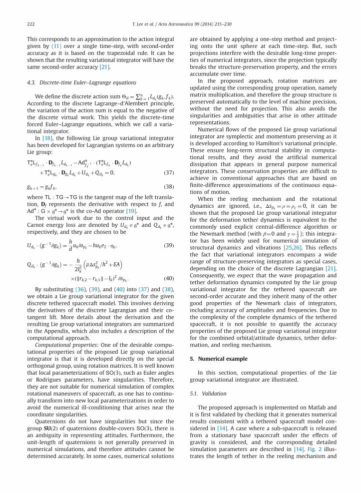
The proposed approach is implemented on Matlab andit is first validated by checking that it generates numericalresults consistent with a tethered spacecraft model con-sidered in [14]. A case where a sub-spacecraft is releasedfrom a stationary base spacecraft under the effects ofgravity is considered, and the corresponding detailedsimulation parameters are described in [14]. Fig. 2 illus-trates the length of tether in the reeling mechanism and
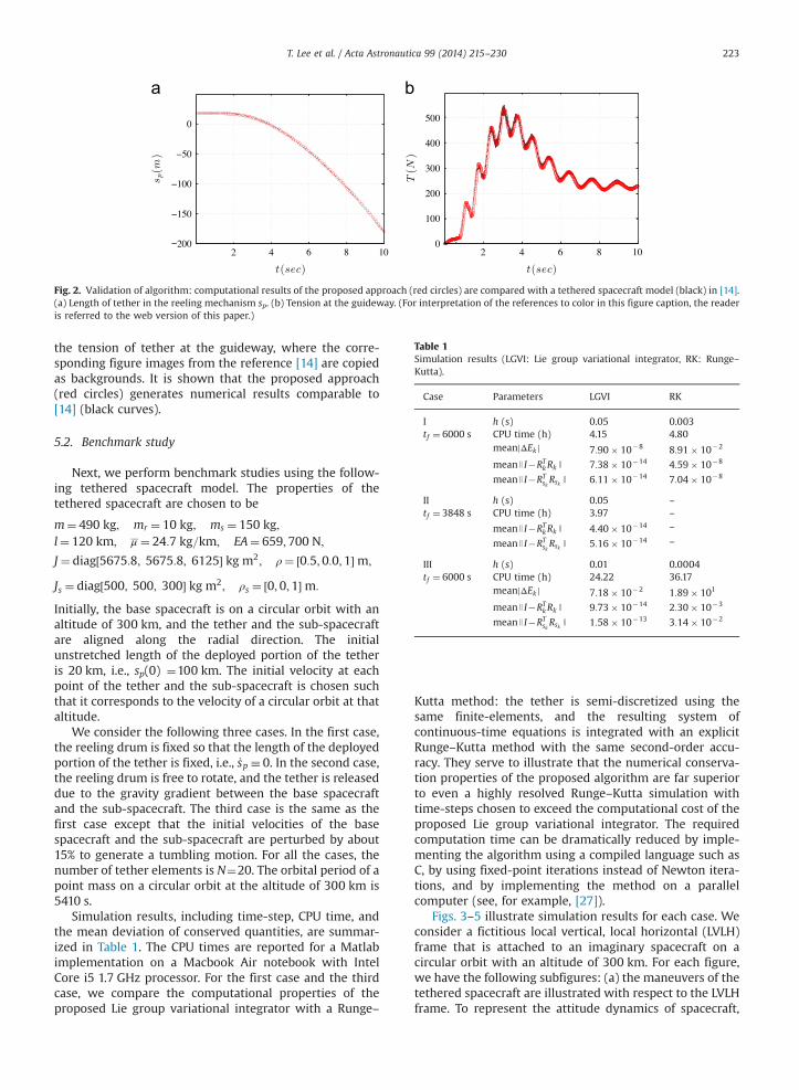
Fig. 2. Validation of algorithm: computational results of the proposed approach (red circles) are compared with a tethered spacecraft model (black) in [14].(a) Length of tether in the reeling mechanism sp. (b) Tension at the guideway. (For interpretation of the references to color in this figure caption, the readeris referred to the web version of this paper.)
Table 1Simulation results (LGVI: Lie group variational integrator, RK: Runge–Kutta).
Case Parameters LGVI RK
I h (s) 0.05 0.003tf ¼ 6000 s CPU time (h) 4.15 4.80
meanjΔEkj 7:90� 10�8 8:91� 10�2
meanJ I�RTkRk J 7:38� 10�14 4:59� 10�8
meanJ I�RTskRsk J 6:11� 10�14 7:04� 10�8
II h (s) 0.05 –
tf ¼ 3848 s CPU time (h) 3.97 –
meanJ I�RTkRk J 4:40� 10�14 –
meanJ I�RTskRsk J 5:16� 10�14 –
III h (s) 0.01 0.0004tf ¼ 6000 s CPU time (h) 24.22 36.17
meanjΔEkj 7:18� 10�2 1:89� 101
meanJ I�RTkRk J 9:73� 10�14 2:30� 10�3
meanJ I�RTskRsk J 1:58� 10�13 3:14� 10�2
T. Lee et al. / Acta Astronautica 99 (2014) 215–230 223
the tension of tether at the guideway, where the corre-sponding figure images from the reference [14] are copiedas backgrounds. It is shown that the proposed approach(red circles) generates numerical results comparable to[14] (black curves).
5.2. Benchmark study
Next, we perform benchmark studies using the follow-ing tethered spacecraft model. The properties of thetethered spacecraft are chosen to be
m¼ 490 kg; mr ¼ 10 kg; ms ¼ 150 kg;l¼ 120 km; μ ¼ 24:7 kg=km; EA¼ 659;700 N;
J ¼ diag½5675:8; 5675:8; 6125� kg m2; ρ¼ ½0:5;0:0;1�m;
Js ¼ diag½500; 500; 300� kg m2; ρs ¼ ½0;0;1�m:
Initially, the base spacecraft is on a circular orbit with analtitude of 300 km, and the tether and the sub-spacecraftare aligned along the radial direction. The initialunstretched length of the deployed portion of the tetheris 20 km, i.e., sp(0) ¼100 km. The initial velocity at eachpoint of the tether and the sub-spacecraft is chosen suchthat it corresponds to the velocity of a circular orbit at thataltitude.
We consider the following three cases. In the first case,the reeling drum is fixed so that the length of the deployedportion of the tether is fixed, i.e., _sp � 0. In the second case,the reeling drum is free to rotate, and the tether is releaseddue to the gravity gradient between the base spacecraftand the sub-spacecraft. The third case is the same as thefirst case except that the initial velocities of the basespacecraft and the sub-spacecraft are perturbed by about15% to generate a tumbling motion. For all the cases, thenumber of tether elements is N¼20. The orbital period of apoint mass on a circular orbit at the altitude of 300 km is5410 s.
Simulation results, including time-step, CPU time, andthe mean deviation of conserved quantities, are summar-ized in Table 1. The CPU times are reported for a Matlabimplementation on a Macbook Air notebook with IntelCore i5 1.7 GHz processor. For the first case and the thirdcase, we compare the computational properties of theproposed Lie group variational integrator with a Runge–
Kutta method: the tether is semi-discretized using thesame finite-elements, and the resulting system ofcontinuous-time equations is integrated with an explicitRunge–Kutta method with the same second-order accu-racy. They serve to illustrate that the numerical conserva-tion properties of the proposed algorithm are far superiorto even a highly resolved Runge–Kutta simulation withtime-steps chosen to exceed the computational cost of theproposed Lie group variational integrator. The requiredcomputation time can be dramatically reduced by imple-menting the algorithm using a compiled language such asC, by using fixed-point iterations instead of Newton itera-tions, and by implementing the method on a parallelcomputer (see, for example, [27]).
Figs. 3–5 illustrate simulation results for each case. Weconsider a fictitious local vertical, local horizontal (LVLH)frame that is attached to an imaginary spacecraft on acircular orbit with an altitude of 300 km. For each figure,we have the following subfigures: (a) the maneuvers of thetethered spacecraft are illustrated with respect to the LVLHframe. To represent the attitude dynamics of spacecraft,
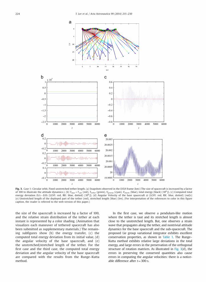
Fig. 3. Case 1: Circular orbit, Fixed unstretched tether length. (a) Snapshots observed in the LVLH frame (km) (The size of spacecraft is increased by a factorof 100 to illustrate the attitude dynamics.). (b) TbaseþTsub (red), Ttether (green), Vgravity (cyan), Velastic (blue), total energy (black) (106 J). (c) Computed totalenergy deviation EðtÞ�Eð0Þ (LGVI: red, RK: blue, dotted) (106 J). (d) Angular Velocity of the base spacecraft Ω (LGVI: red, RK: blue, dotted) (rad/s)(e) Unstretched length of the deployed part of the tether (red), stretched length (blue) (km). (For interpretation of the references to color in this figurecaption, the reader is referred to the web version of this paper.)
T. Lee et al. / Acta Astronautica 99 (2014) 215–230224
the size of the spacecraft is increased by a factor of 100,and the relative strain distribution of the tether at eachinstant is represented by a color shading. (Animation thatvisualizes each maneuver of tethered spacecraft has alsobeen submitted as supplementary materials.) The remain-ing subfigures show (b) the energy transfer, (c) thecomputed total energy deviation from its initial value, (d)the angular velocity of the base spacecraft, and (e)the unstretched/stretched length of the tether. For thefirst case and the third case, the computed total energydeviation and the angular velocity of the base spacecraftare compared with the results from the Runge–Kuttamethod.
In the first case, we observe a pendulum-like motionwhere the tether is taut and its stretched length is almostclose to the unstretched length. But, one observes a strainwave that propagates along the tether, and nontrivial attitudedynamics for the base spacecraft and the sub-spacecraft. Theproposed Lie group variational integrator exhibits excellentconservation properties, as shown in Table 1. The Runge–Kutta method exhibits relative large deviations in the totalenergy, and large errors in the preservation of the orthogonalstructure of rotation matrices. As illustrated in Fig. 3(d), theerrors in preserving the conserved quantities also causeerrors in computing the angular velocities: there is a notice-able difference after t¼300 s.
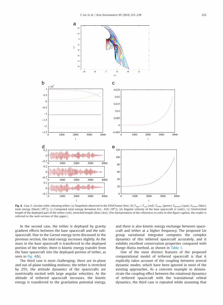
Fig. 4. Case 2: circular orbit, releasing tether. (a) Snapshots observed in the LVLH frame (km). (b) TbaseþTsub (red), Ttether (green), Vgravity (cyan), Velastic (blue),total energy (black) (106 J). (c) Computed total energy deviation EðtÞ�Eð0Þ (106 J). (d) Angular velocity of the base spacecraft Ω (rad/s). (e) Unstretchedlength of the deployed part of the tether (red), stretched length (blue) (km). (For interpretation of the references to color in this figure caption, the reader isreferred to the web version of this paper.)
T. Lee et al. / Acta Astronautica 99 (2014) 215–230 225
In the second case, the tether is deployed by gravitygradient effects between the base spacecraft and the sub-spacecraft. Due to the Carnot energy term discussed in theprevious section, the total energy increases slightly. As themass in the base spacecraft is transferred to the deployedportion of the tether, there is kinetic energy transfer fromthe base spacecraft into the deployed portion of tether, asseen in Fig. 4(b).
The third case is most challenging: there are in-planeand out-of-plane tumbling motions; the tether is stretchedby 25%; the attitude dynamics of the spacecrafts arenontrivially excited with large angular velocities. As thealtitude of tethered spacecraft increases, the kineticenergy is transferred to the gravitation potential energy,
and there is also kinetic energy exchange between space-craft and tether at a higher frequency. The proposed Liegroup variational integrator computes the complexdynamics of this tethered spacecraft accurately, and itexhibits excellent conservation properties compared withRunge–Kutta method, as shown in Table 1.
One of the most distinct features of the proposedcomputational model of tethered spacecraft is that itexplicitly takes account of the coupling between severaldynamic modes, which have been ignored in most of theexisting approaches. As a concrete example to demon-strate the coupling effect between the rotational dynamicsof tethered spacecraft with the translational orbitaldynamics, the third case is repeated while assuming that
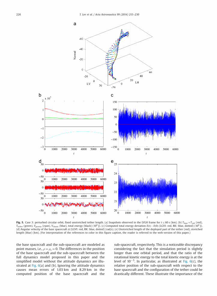
Fig. 5. Case 3: perturbed circular orbit, fixed unstretched tether length. (a) Snapshots observed in the LVLH frame for tr60 s (km). (b) TbaseþTsub (red),Ttether (green), Vgravity (cyan), Velastic (blue), total energy (black) (106 J). (c) Computed total energy deviation EðtÞ�Eð0Þ (LGVI: red, RK: blue, dotted) (106 J).(d) Angular velocity of the base spacecraft Ω (LGVI: red, RK: blue, dotted) (rad/s). (e) Unstretched length of the deployed part of the tether (red), stretchedlength (blue) (km). (For interpretation of the references to color in this figure caption, the reader is referred to the web version of this paper.)
T. Lee et al. / Acta Astronautica 99 (2014) 215–230226
the base spacecraft and the sub-spacecraft are modeled aspoint masses, i.e., ρ¼ ρs ¼ 0. The differences in the positionof the base spacecraft and the sub-spacecraft between thefull dynamics model proposed in this paper and thesimplified model without the attitude dynamics are illu-strated at Fig. 6(a) and (b). Ignoring the attitude dynamicscauses mean errors of 1.03 km and 8.29 km in thecomputed position of the base spacecraft and the
sub-spacecraft, respectively. This is a noticeable discrepancyconsidering the fact that the simulation period is slightlylonger than one orbital period, and that the ratio of therotational kinetic energy to the total kinetic energy is at thelevel of 10�5. In particular, as illustrated at Fig. 6(c), therelative position of the sub-spacecraft with respect to thebase spacecraft and the configuration of the tether could bedrastically different. These illustrate the importance of the
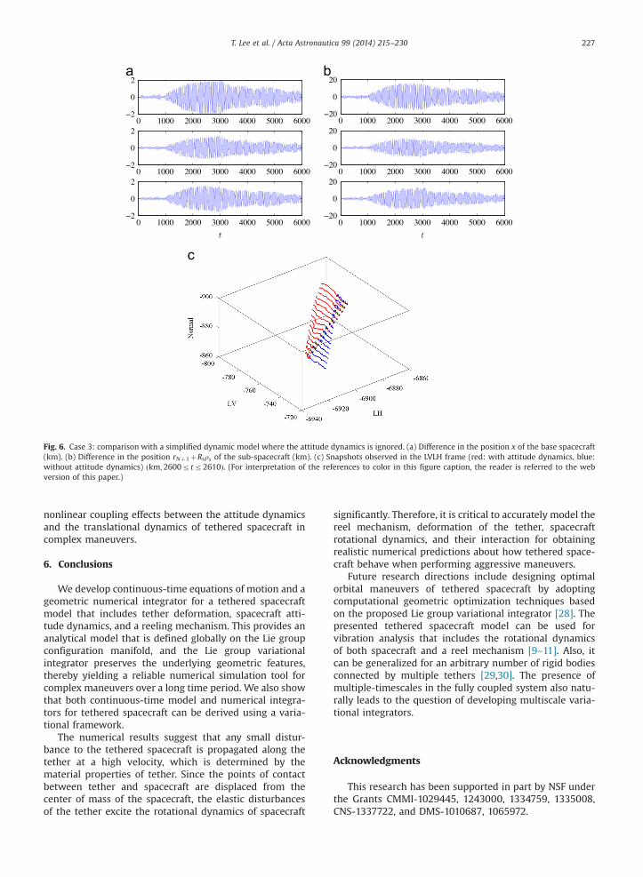
Fig. 6. Case 3: comparison with a simplified dynamic model where the attitude dynamics is ignored. (a) Difference in the position x of the base spacecraft(km). (b) Difference in the position rNþ1þRsρs of the sub-spacecraft (km). (c) Snapshots observed in the LVLH frame (red: with attitude dynamics, blue:without attitude dynamics) ðkm;2600rtr2610Þ. (For interpretation of the references to color in this figure caption, the reader is referred to the webversion of this paper.)
T. Lee et al. / Acta Astronautica 99 (2014) 215–230 227
nonlinear coupling effects between the attitude dynamicsand the translational dynamics of tethered spacecraft incomplex maneuvers.
6. Conclusions
We develop continuous-time equations of motion and ageometric numerical integrator for a tethered spacecraftmodel that includes tether deformation, spacecraft atti-tude dynamics, and a reeling mechanism. This provides ananalytical model that is defined globally on the Lie groupconfiguration manifold, and the Lie group variationalintegrator preserves the underlying geometric features,thereby yielding a reliable numerical simulation tool forcomplex maneuvers over a long time period. We also showthat both continuous-time model and numerical integra-tors for tethered spacecraft can be derived using a varia-tional framework.
The numerical results suggest that any small distur-bance to the tethered spacecraft is propagated along thetether at a high velocity, which is determined by thematerial properties of tether. Since the points of contactbetween tether and spacecraft are displaced from thecenter of mass of the spacecraft, the elastic disturbancesof the tether excite the rotational dynamics of spacecraft
significantly. Therefore, it is critical to accurately model thereel mechanism, deformation of the tether, spacecraftrotational dynamics, and their interaction for obtainingrealistic numerical predictions about how tethered space-craft behave when performing aggressive maneuvers.
Future research directions include designing optimalorbital maneuvers of tethered spacecraft by adoptingcomputational geometric optimization techniques basedon the proposed Lie group variational integrator [28]. Thepresented tethered spacecraft model can be used forvibration analysis that includes the rotational dynamicsof both spacecraft and a reel mechanism [9–11]. Also, itcan be generalized for an arbitrary number of rigid bodiesconnected by multiple tethers [29,30]. The presence ofmultiple-timescales in the fully coupled system also natu-rally leads to the question of developing multiscale varia-tional integrators.
Acknowledgments
This research has been supported in part by NSF underthe Grants CMMI-1029445, 1243000, 1334759, 1335008,CNS-1337722, and DMS-1010687, 1065972.
T. Lee et al. / Acta Astronautica 99 (2014) 215–230228
Appendix A. Derivation of the Lie group variationalintegrator for a tethered spacecraft
A.1. Derivatives of the discrete Lagrangian
The Lie group variational integrator given by (37) isexpressed in terms of the derivatives of the discreteLagrangian and their co-tangent lift. Here, we describehow to compute the co-tangent lift and the co-Adjointoperator on the configuration manifold G¼R3 � SOð3Þ�R� ðR3ÞNþ1 � SOð3Þ without introducing the formal defi-nition of those operators.
The co-tangent lift of the left translation on a real spaceis the identity map on that real space. Using the productstructure of the configuration manifold G¼R3�SOð3Þ � R� ðR3ÞNþ1 � SOð3Þ, the derivative of the dis-crete Lagrangian with respect to f k ¼ ðΔxk; Fk;Δspk ;Δrk;1;…;Δrk;Nþ1; Fsk ÞAG is given by
Tn
eLf k � Df k Ldk ¼ ½DΔxk Ldk ; Tn
I LFk � DFkLdk ; DΔspkLdk ;
DΔr1;k Ldk ;…;DΔrNþ 1;k Ldk ; Tn
I LFsk � DFskLdk �: ðA:1Þ
Deriving the derivatives of the discrete Lagrangian withrespect to Δxk, Δspk or Δrk;a is relatively straightforward.For example, from (31), (34), and (36), the derivatives ofthe discrete Lagrangian with respect to xk;Δxk are given by
DΔxk Ldk ¼1h
mþmrþμspk� �
Δxk�h2Dxkþ 1Vkþ1; ðA:2Þ
Dxk Ldk ¼ � h2DxkVk�
h2Dxkþ 1Vkþ1; ðA:3Þ
where
DxkVk ¼ GM mþmrþμspk� � xk
Jxk J3:
Similarly, from (32), the derivative of the discrete Lagran-gian with respect to Δrk;a for a¼2,…,N is given by
DΔrk;a Ldk ¼ h DΔrk;a Tk;a�1þDΔrk;a Tk;a� �� h
2DΔrk;aVkþ1
¼ 1hM12
k Δrk;a�1þ2hM1
kΔrk;aþ1hM12
k Δrk;aþ1
þ 1h
M31k;aþM23
k;a�1
Δspk �
h2Drkþ 1;aVkþ1; ðA:4Þ
where the derivative of the potential energy is given by
Drk;aVk ¼ 2GMμlkrk;a�1þrk;a
Jrk;a�1þrk;a J3þ2GMμlk
rk;aþrk;aþ1
Jrk;aþrk;aþ1 J3
þ∇Vek;a�1�∇Ve
k;a; ðA:5Þ
∇Vek;a ¼
EAlk
‖rk;aþ1�rk;a‖� lk‖rk;aþ1�rk;a‖
rk;aþ1�rk;a� �
: ðA:6Þ
Expressions for the other derivatives of the discreteLagrangian with respect to spk , Δspk , rk1 , Δrk1 , rk;Nþ1,Δrk;Nþ1 can be developed similarly.
Now we find the derivative of the discrete Lagrangianwith respect to Fk. From (31), (35), and (36), we have
DFkLdk � δFk ¼1htr �δFkJd� �
:
Similar to (12), the variation of the rotation matrix Fk can bewritten as δFk ¼ Fkζ for a vector ζAR3. From the definition of
the co-tangent lift of the left translation, we have
Tn
I LFk � DFk Ldk� � � ζ¼ 1
htr �FkζkJdh i
:
By repeatedly applying the following property of the trace
operator, tr½AB� ¼ tr½BA� ¼ tr½ATBT � for any A;BAR3�3, this can
be written as tr �FkζkJdh i
¼ tr � ζkJdFkh i
¼ tr ζkh
FTk Jd� ¼
�12 tr ζk JdFk�FTk Jd
h i. Using the property of the hat map,
xTy¼ �12 tr xy
� �for any x; yAR3, this can be further written
as
Tn
I LFk � DFkLdk ¼1hðJdFk�FTk JdÞ3 : ðA:7Þ
Similarly, we obtain
Tn
I LFsk � DFskLdk
¼ 1hðJsd Fsk �FTsk Jsd Þ
3 þ ms
hρsF
TskRTskΔrk;Nþ1
� h2GMmsρsF
TskRTsk
rkþ1;Nþ1þRskþ 1ρs
Jrkþ1;Nþ1þRskþ 1ρs J3 : ðA:8Þ
Expression for the derivatives of the discrete Lagrangian withrespect to Rk and Rsk are similarly developed.
The Lie group variational integrator given by (37) alsoinvolves the co-Adjoint map [19]. Using the productstructure of the configuration manifold, the second termof (37), namely Adn
f � 1kðTn
eLf k � Df k Ldk Þ; corresponds to thecollection of the co-Adjoint maps for each element ofTn
eLf k � Df k Ldk given by (A.1).The co-Adjoint map on a real space is the identity map
on that real space. For example,
Adn
�Δxk ðDΔk Ldk Þ ¼DΔk Ldk : ðA:9Þ
The co-Adjoint map on SOð3Þ is given by Adn
F � 1k
p¼ Fkp¼ ðFkpFTk Þ3 for any pAðR3ÞnCsoð3Þn to obtain
Adn
FTkTn
I LFk � DFk Ldk� �¼ 1
hðFkJd� JdFkÞ3 ; ðA:10Þ
Adn
FTskTn
I LFsk � DFskLdk
¼ 1
hðFsk Jsd � Jsd F
TskÞ3 þ ms
hFsk ρsF
TskRTskΔrk;Nþ1
� h2GMmsFsk ρsF
TskRTsk
rkþ1;Nþ1þRskþ 1ρs
Jrkþ1;Nþ1þRskþ 1ρs J3 : ðA:11Þ
1h
mþmrþμspk� �
Δxkþ1hM1
kΔrk;1þ1hM12
k Δrk;2þ1hM31
k;1Δspk
¼ 1h
mþmrþμspk� 1
� �Δxk�1þ
1hM1
k�1Δrk�1;1
þ 1hM12
k�1Δrk�1;2þ1hM31
k�1;1Δspk� 1
þ μ
6Nh3N�2ð ÞΔspkΔrk;2þ
μ
6Nh3N�1ð ÞΔspkΔrk;1
�hDxkVk�hDrk;1Vk; ðA:12Þ
xkþΔxkþRkFkρ¼ rk;1þΔrk;1; ðA:13Þ
1hM0
kΔspk þ1hM31
k;1Δrk;1þ1h
∑N
a ¼ 2M31
k;aþM23k;a�1
Δrk;a
þ 1hM23
k;NΔrk;Nþ1
T. Lee et al. / Acta Astronautica 99 (2014) 215–230 229
¼ 1hM0
k�1Δspk� 1þ 1
hM31
k�1;1Δrk�1;1þ1h
∑N
a ¼ 2ðM31
k�1;a
þM23k�1;a�1ÞΔrk�1;aþ
1hM23
k�1;NΔrk�1;Nþ1
þ 12h
μΔxk � Δxkþ13h
μΔs2pk �μ
6Nh∑N
a ¼ 1Δrk;a � Δrk;a�
þΔrk;aþ1 � Δrk;aþ1þΔrk;a � Δrk;aþ1�
�hDspkVkþh
uk
d� h
2l2kμΔs2pk=h
2þEA
ð‖rk;2�rk;1‖� lkÞ2;
ðA:14Þ
1hM12
k Δrk;a�1þ2hM1
kΔrk;aþ1hM12
k Δrk;aþ1
þ 1h
M31k;aþM23
k;a�1
Δspk
¼ 1hM12
k�1Δrk�1;a�1þ2hM1
k�1Δrk�1;a
þ 1hM12
k�1Δrk�1;aþ1þ1hðM31
k�1;aþM23k�1;a�1ÞΔspk� 1
þ μ
6Nh1þ3N�3að ÞΔspkΔrk;aþ1�
μ
3NhΔspkΔrk;a
� μ
6Nh5þ3N�3að ÞΔspkΔrk;a�1�hDrk;aVk; ðA:15Þ
1h
M2kþms
Δrk;Nþ1þ
1hM12
k Δrk;Nþ1hM23
k;NΔspk
þ 1hmsRsk Fsk � I
� �ρs
¼ 1h
M2k�1þms
Δrk�1;Nþ1þ
1hM12
k�1Δrk�1;N
þ 1hM23
k�1;NΔspk� 1þ 1
hmsRsk Fsk� 1 � I
� �ρs
� μ
6NhΔspkΔrk;Nþ1�
μ
3NhΔspkΔrk;N�hDrk;Nþ 1Vk;
ðA:16Þ
1hðFkJd� JdF
Tk Þ3 þ ρRT
k1hM1
kΔrk;1þ1hM12
k Δrk;2þ1hM31
k;1Δspk
� �
¼ 1hðJdFk�1�FTk�1JdÞ3 þ ρRT
k1hM1
k�1Δrk�1;1
�
þ 1hM12
k�1Δrk�1;2þ1hM31
k�1;1Δspk �1
�
þ ρRTk
�μ
6Nh3N�2ð ÞΔspkΔrk;2þ
μ
6Nh3N�1ð ÞΔspkΔrk;1
�hDrk;1Vk
��huke2; ðA:17Þ
1hðFsk Jsd � Jsd F
TskÞ3 ¼ 1
hðJsd Fsk� 1 �FTsk� 1
Jsd Þ3
� ms
hρsR
Tsk
Δrk;Nþ1�Δrk�1;Nþ1� �
�hGMmsρsRTsk
rk;Nþ1þRskρsJrk;Nþ1þRskρs J
3 :
ðA:18ÞA.2. Lie group variational integrator
Once the derivatives of the discrete Lagrangian and theirco-Adjoint maps are obtained, they are substituted into (37)and (38) with the contributions of the external controlmoment (39), and the Carnot energy loss term (40). Theresulting discrete-time Euler–Lagrange equations of tethered
spacecraft are given by (A.12)–(A.18), where the constraint onthe continuity of the tether at the beginning of the guidewaywhich is given by (A.13) and (A.15) is satisfied for a¼2,…,N.
For a given gk ¼ ðxk;Rk; spk ; rk;1;…rk;Nþ1;Rsk Þ, we solve(A.12)–(A.15) for the relative update f k ¼ ðΔxk; Fk;Δspk ;Δrk;1;…, Δrk;Nþ1; Fsk Þ. Then, the configuration at the nextstep, namely gkþ1 is obtained by (30). This yields a discrete-time Lagrangian flow map ðgk; f kÞ↦ðgkþ1; f kþ1Þ, and this isiterated.
Special cases: If we set Δspk � 0 for all k, then thediscrete-time Euler–Lagrange equations provide a geo-metric numerical integrator for tethered spacecraft witha fixed unstretched tether length. If we chose ρ¼ ρc ¼ 0,then these equations describe the dynamics of two pointmasses connected by tether and a reeling mechanism.
Computational approach: These Lie group variational inte-grators for tethered spacecraft are implicit: at each time-step,we need to solve nonlinear implicit equations to find therelative update f kAG. Therefore, it is important to develop anefficient computational approach for these implicit equations.This computational method should preserve the group struc-ture of fk, and in particular, the orthogonal structure of therotation matrix FkASOð3Þ should be preserved. The key ideaof the computational approach proposed in this paper is toexpress the rotation matrix Fk in terms of a vector ckAR3
using the Cayley transformation [17]:
Fk ¼ ðIþ ckÞðI� ckÞ�1: ðA:19ÞSince the rotation matrix Fk represents the relative attitudeupdate between two adjacent integration steps, it is a near-to-identity transformation when the time-step h is sufficientlysmall. As such, the expression above remains valid fornumerical simulations even though the Cayley transformationis only a local diffeomorphism between R3 and SOð3Þ aboutck¼0 and Fk ¼ I.
Our computational approach is as follows. The implicitequations for Fk and Fsk , namely (A.17) and (A.18), arerewritten in terms of vectors ck, csk using (A.19). Then, therelative update map is expressed by a vector Xk ¼ ½Δxk;ck;Δspk ;Δrk;1;…Δrk;Nþ1; csk �AR3ðNþ1Þþ10, which is solvedby using a Newton iteration. After the vector Xk converges,the rotation matrices Fk and Fsk are computed by (A.19), toobtain f kAG.
This computational approach is desirable, since the implicitequations are solved numerically using operations in a linearvector space. Rotation matrices, Fk and Fsk , are computed bynumerical iterations on R6, and its orthogonal structure isautomatically preserved by (A.19). It has been shown that thiscomputational approach is numerically efficient [23].
Appendix B. Supplementary material
Supplementary data associated with this paper can befound in the online version of http://dx.doi.org/10.1016/j.actaastro.2014.02.021.
References
[1] M. Cosmo, E. Lorenzini, Tethers in Space Handbook, TechnicalReport, NASA Marshall Space Flight Center, 1997.
T. Lee et al. / Acta Astronautica 99 (2014) 215–230230
[2] E. Lorenzini, M. Grossi, M. Cosmo, Low altitude tethered mars probe,Acta Astronaut. 21 (1990) 1–12.
[3] L. Less, C. Bruno, C. Ullvieri, U. Ponzi, M. Parisse, G. Laneve, G. Vannaroni,M. Dobrowolny, F. De Venuto, B. Bertotti, L. Anselmo, Satellite de-orbitingby means of electrodynamic tethers, Part I: general concepts andrequirements, Acta Astronaut. 50 (2002) 399–406.
[4] Young engineers' satellite 2, European Space Agency, URL: ⟨http://www.esa.int/SPECIALS/YES/index.html⟩.
[5] P. Williams, Simple approach to orbital control using spinningelectrodynamic tethers, J. Spacecraft Rockets 43 (2006) 253–256.
[6] V. Beletsky, E. Levin, Dynamics of Space Tether Systems AmericanAstronautical Society, Washington DC, 1993.
[7] L. Somenzi, L. Iess, J. Pelaez, Linear stability analysis of electrody-namic tethers, J. Guid. Control Dyn. 28 (2005) 843–849.
[8] G. Tyc, R. Han, Attitude dynamics investigation of the OEDIPUS-Atethered rocket payload, J. Spacecraft Rockets 32 (1995) 133–141.
[9] A. Misra, D. Xu, On vibrations of orbiting tethers, Acta Astronaut. 13(1986) 587–597.
[10] S. Kalaycioglu, A. Misra, Approximate solutions for vibrations ofdeploying appendages, J. Guid. Control Dyn. 14 (1991) 287–293.
[11] F. Vigneron, A. Jablonski, R. Chandrashaker, J. Bergmans, B. McClure,G. Tyc, Comparison of analytical modeling of OEDIPUS tethers withdata from tether laboratory, J. Guid. Control Dyn. 20 (1997) 471–478.
[12] W. Steiner, J. Zemann, A. Steindl, H. Troger, Numerical study of largeamplitude oscillations of a two-satellite continuous tether systemwith a varying length, Acta Astronaut. 35 (1995) 607–621.
[13] M. Krupa, W. Poth, M. Schagerl, A. Steindl, W. Steiner, H. Troger,Modelling, dynamics and control of tethered satellites systems,Nonlinear Dyn. 43 (2006) 73–96.
[14] K. Mankala, S. Agrawal, Dynamic modeling and simulationof satellite tethered systems, ASME J. Vib. Acoust. 127 (2005)144–156.
[15] T. Lee, M. Leok, N. McClamroch, Computational dynamics of a 3Delastic string pendulum attached to a rigid body and an inertiallyfixed reel mechanism, Nonlinear Dyn. 64 (2011) 97–115.
[16] T. Lee, M. Leok, N. McClamroch, Dynamics of a 3D elastic stringpendulum, in: Proceedings of IEEE Conference on Decision andControl, 2009, pp. 3347–3352.
[17] E. Hairer, C. Lubich, G. Wanner, Geometric Numerical Integration.Springer Series in Computational Mechanics, vol. 31, Springer, NewYork, 2000.
[18] T. Lee, Computational geometric mechanics and control of rigidbodies (Ph.D. thesis), University of Michigan, 2008.
[19] J. Marsden, T. Ratiu, 2nd ed. Introduction to Mechanics and Sym-metry of Texts in Applied Mathematics, vol. 17, Springer-Verlag,1999.
[20] E. Crellin, F. Janssens, D. Poelaert, W. Steiner, H. Troger, On balanceand variational formulations of the equations of motion of a bodydeploying along a cable, J. Appl. Mech. 64 (1997) 369–374.
[21] J. Marsden, M. West, Discrete mechanics and variational integrators,in: Acta Numerica, vol. 10, Cambridge University Press, Cambridge,UK, 2001, pp. 317–514.
[22] A. Iserles, H. Munthe-Kaas, S. Nørsett, A. Zanna, Lie-group methods,in: Acta Numerica, vol. 9, Cambridge University Press, Cambridge,UK, 2000, pp. 215–365.
[23] T. Lee, M. Leok, N.H. McClamroch, Lie group variational integratorsfor the full body problem in orbital mechanics, Celest. Mech. Dyn.Astron. 98 (2007) 121–144.
[24] B. Leimkuhler, S. Reich, Simulating Hamiltonian Dynamics, Cam-bridge Monographs on Applied and Computational Mathematics,vol. 14, Cambridge University Press, Cambridge, UK, 2004.
[25] N. Newmark, A method of computation for structural dynamics,ASCE J. Eng. Mech. 85 (1959) 67–94.
[26] T. Hughes, The Finite Element Method—Linear Static and DynamicFinite Element Analysis, Prentice Hall, Upper Saddle River, NJ, 1987.
[27] D. Scheeres, E. Fahnestock, S. Ostro, J. Margot, L. Benner, S. Broschart,J. Bellerose, J. Giorgini, M. Nolan, C. Magri, P. Pravec, P. Scheirich,R. Rose, R. Jurgens, E.D. Jong, S. Suzuki, Dynamical configuration ofbinary near-Earth asteroid (66391) 1999 KW4, Science 314 (2006)1280–1283.
[28] T. Lee, M. Leok, N.H. McClamroch, Computational geometric optimalcontrol of rigid bodies, Commun. Inf. Syst. 8 (2008) 445–472.(Special issue dedicated to R.W. Brockett).
[29] A. Misra, V. Modi, Three-dimensional dynamics and control oftether-connected n-body systems, Acta Astronaut. 26 (1992) 77–84.
[30] A. Misra, G. Diamond, Dynamics of a subsatellite system supportedby two tethers, J. Guid. Control Dyn. 9 (1986) 12–16.