Embed Size (px)
Citation preview

Zyla 5.5 HFHigh Energy ImagingFiber Optic Indirect Detection5.5 Megapixel sCMOS
1
High E
nergy Detection
Features and Benefits• Rapid frame rates
100 fps full frame sustained
• Fiber optic plate coupling •1
Direct bonding on sCMOS sensor for maximum throughput. EMA statistical structure for lowest channel crosstalk
• 5.5 megapixel sensor format with high resolution and 6.5 μm pixelsLarge 16.6 x 14 mm field of view
• 1.2 e- read noiseLower detection limit than any CCD
• Compact and light Ideal for integration into space restrictive set-ups
• Rolling and Global shutter Maximum flexibility across all application
• Dual-Gain amplifiersExtensive dynamic range of 25,000:1@ 30 fps
• ROI and pixel binningUser-defined ROI (1 pixel granularity) and hardware binning
• Dynamic baseline clamp Ensures quantitative stability
• Hardware time stampFPGA generated time stamp with 25 ns accuracy
• Modular input interfaceChoice of high resolution / high throughput scintillators and Beryllium filters
• Integrated in EPICSPlatform is fully integrated into the EPICS control software
Zyla Fiber Optic sCMOS- X-Ray Imaging at 100 fpsAndor’s Zyla 5.5 HF outstanding design delivers the highest transmission and spatial resolution
performance associated with state-of-the-art single fiber optic plate bonding, while also taking
advantage of the very fast frame rate, ultra-low noise performance and exceptional field of view of
the Zyla 5.5.
Its compact format, multiple mounting points and modular input configuration for scintillators
or Beryllium filter integration allow ease of integration into laboratory setup or integrator (OEM)
systems.
This unique feature combination makes the Zyla 5.5 HF the perfect detector platform for applications including X-ray imaging & tomography, electron microscopy and picosecond/nanosecond X-ray imaging when coupled to streak tubes or open MCPs.
Specifications Summary•2
Active pixels (W x H) 2560 x 2160 (5.5 Megapixel)
Sensor size 16.6 x 14.0 mm (21.8 mm diagonal)
Pixel size (W x H) 6.5 µm
Pixel well depth (typical) 30,000 e-
Readout speeds (MHz) 560, 200
Read noise 1.2 e-
Sensor operating temperature 0°C
Maximum frame rate 100 fps @ full frame
High resolution phase-contrast enhanced X-ray image of mouse pawCourtesy of 4DX Pty. Ltd., Melbourne, Australia.
NEW! sCMOS for Indirect Detection

Zyla 5.5 HFHigh Energy ImagingFiber Optic Indirect Detection5.5 Megapixel sCMOS
2
Extra-mural absorber (EMA) fiber
Imaging fiber
3 µm
Array SizeZyla 5.5 (10-tap)
Rolling Shutter Global Shutter
2560 x 2160 (full frame) 100 50
2048 x 2048 105 52
1920 x 1080 198 97
512 x 512 419 201
128 x 128 1,639 721
3 High spatial resolution
High resolution AND high throughput AND low crosstalk fiber-optic plate2
sCMOS technology: high speed AND low noise AND large field of view
Scientific CMOS overcomes the limitation of traditional slow-scan CCDs or interline technologies by offering simultaneously a large 16.6 x 14 mm (5.5 Megapixel) field of view with high resolution 6.5 µm pixel,100 frames per second and ultralow 1.2 e- read noise.
1
Learn more at: http://www.andor.com/learning-academy/scmos-technology-what-is-scmos
16.6 mm
14 mm 21.8 mm
40.3 Ip/mm
50.8 Ip/mm
36 Ip/mm
45.3 Ip/mm
57 Ip/mm
32 Ip/mm
1:1 image of a USAF resolving Power Test Target 1951 acquired with a Zyla 5.5 HF - features up to 50 lp/mm
can be resolved
Cross section
Single fiber direct bonding onto sensor
EMA (Extra-Mural Absorption) statistical structureLight-absorbing glass structures are inserted into the matrix as replacements for individual light-conducting fibers, absorbing stray photons not contained by the individual fibers and leading to the lowest fiber crosstalk.
Left: Zyla 5.5 HF offers a wide field of view
Above: Zyla 5.5 HF delivers exceptionally high frame rates in both Rolling Shutter and Global Shutter modes.

Zyla 5.5 HFHigh Energy ImagingFiber Optic Indirect Detection5.5 Megapixel sCMOS
3
Sensor Specifications•2
Sensor type Front Illuminated Scientific CMOS with FOP
Active pixels •3 2560 x 2160 (5.5 Megapixel)
Pixel size 6.5 x 6.5 µm
Image area 16.6 x 14.0 mm21.8 mm diagonal with 100% fill factor
Blemish specification Grade 1 sensor as per manufacturer definition
Maximum quantum efficency •4 60% @ 580 nm
Advanced Performance Specifications•2
Sensor Operating Temperature 0ºC (up to 35ºC ambient)
Dark current, e-/pixel/sec @ min temp •5 0.14
Pixel well depth 30,000 e-
Read noise (e-) Median [rms] •6 Rolling Shutter Global Shutter (snapshot) @ 200 MHz 1.2 [1.7] 2.4 [2.7] @ 560 MHz 1.45 [1.8] 2.6 [2.9]
Linearity •7 Better than 99%
Data range 12-bit and 16-bit
Maximum dynamic range 25,000:1
Pixel binning Hardware Binning: 2 x 2, 3 x 3, 4 x 4, 8 x 8
Trigger modes Internal, External, External Start, External Exposure, Software Trigger
Software Exposure Events •8 Start exposure - End exposure (row 1), Start exposure - End exposure (row n)
Hardware timestamp accuracy 25 ns
Anti-blooming factor x 10,000
Optional Scintillator Specifications•10
Part Code DescriptionWavelength/
Energy Range
Outer dimension
(mm)
Effective area(mm)
Substrate thickness
(mm)
CsI Scintillator thickness
(µm)
Relative light output (%)•11, 12
ContrastTransferFunction
@ 10 lp/mm (%)•12
ACC-OPT-01471 High Throughput: CsI (Tl) 10 keV to 100 keV 50 x 50 47 x 47 3 150 70 18
ACC-OPT-01472 High Resolution: CsI (Tl) 10 keV to 100 keV 50 x 50 47 x 47 3 150 40 33
Fiber Optic Input•9
EMA Design Statistical
Fiber Diameter 3 µm
Core : Cladding ratio 80 : 20
Resolution 128 Ip/mm
Image Distortion Shear: sub 6.5 µm pixel
Gross: sub 6.5 µm pixel

Zyla 5.5 HFHigh Energy ImagingFiber Optic Indirect Detection5.5 Megapixel sCMOS
4
Have you found what you are looking for?
Need to get even closer to the action? Andor’s range of SX/HX cameras are designed for use inside vacuum
chambers.
Need a standalone camera for X-ray? A custom built Beryllium window is fitted as standard to our SY/HY range of
cameras to block visible light.
Need a specific mounting? Contact our experienced design team so we can make the perfect fit.
Need a camera for VUV / X-ray spectroscopy? Andor’s specialist spectrographic cameras (SO 920 or SO 940) are
ideally suited for vacuum spectrographs.
Need a customised version? Please contact us to discuss our Customer Special Request options.
Sensor Quantum Efficiency Curve •4
Filter & Scintillator Holder - ACC-MEC-08444(filter and scintillator plate may be supplied separately)
0
10
20
30
40
50
60
70
400 500 600 700 800 900 1000
Qua
ntum
effi
cien
cy (%
)
Wavelength (nm)
Scintillator plate
50 x 50 x 3 mm
Beryllium window
Ø 56 x 0.20 mm thick
Filter Holder(Used only when Be window installed) Mounted by M4 x 12 countersunk screws (4 off)
Scintillator HolderMounted by M4 x 16 caphead screws (4 off)

Zyla 5.5 HFHigh Energy ImagingFiber Optic Indirect Detection5.5 Megapixel sCMOS
5
Creating The Optimum Product for You
How to customize the Zyla 5.5 HF:
Please indicate which scintillator option you require. Select from no scintillator, high resolution or high throughput options.
Step 3.
Please indicate which software you require.
Step 4.
Choose sensor type Front illuminated scientific CMOS with FOP
Step 1.
example shown
The Zyla 5.5 HF sCMOS comes with a single sensor type.
Step 1.
The Zyla 5.5-HF requires at least one of the following software options:
Solis for Imaging A 32-bit and fully 64-bit enabled application for Windows (Vista, 7 and 8) offering rich functionality for data acquisition and processing. AndorBasic provides macro language control of data acquisition, processing, display and export.
Andor iQ A comprehensive multi-dimensional imaging software package. Offers tight synchronization of the camera with a comprehensive range of microscopy hardware, along with comprehensive rendering and analysis functionality. Modular architecture for best price/performance package on the market.
Andor SDK A software development kit that allows you to control the Andor range of cameras from your own application. Available as 32 and 64-bit libraries for Windows (Vista, 7 and 8), compatible with C/C++, C#, Delphi, VB6, VB.NET, LabVIEW and Matlab. Linux SDK compatible with C/C++.
Third party software compatibility Drivers are available so that the Zyla range can be operated through a large variety of third party imaging packages. See Andor web site for detail: http://www.andor.com/software/
Step 4.
Step 5.
The following accessories are available:
FILTER & SCINTILLATOR HOLDER- ACC-MEC-08444 holder accessory for use with Beryllium
and Scintillator filters (see page 4)
BERYLLIUM FILTER- ACC-OPT-07875, Beryllium foil (Ø 56 mm, 200 microns thick)SCINTILLATOR- ACC-OPT-01471 (High Throughput) or ACC-OPT-01472 (High Resolution).
See page 3 for further details.
5 METER CAMERA LINK CONNECTOR CABLE. ACC-ASE-02992 Note, 2 required for Zyla
5.5 Camera Link 10-tap model.
10 METER ACTIVE CAMERA LINK CONNECTOR CABLE, includes power supply. ACC-ASE-06962
WKST-1 WIN PC Workstation for up to 100 fps continuous spooling to hard drives, acquiring up to 120,000 12-bit full resolution images: Dell T7610, 2.3 GHz Six Core, 8 GB RAM, 4 x 250GB SSD hard drive configured in RAID 0.
WKST-2 WIN PC Workstation for up to 30 fps continuous spooling to RAM, acquiring up to 60,000 12-bit full resolution images: Dell T36010, 3.6 GHz Quad Core, 8 GB RAM, 2 x 250 GB SSD hard drives configured in RAID 0.
WKST-3 WIN PC Workstation for up to 100 fps continuous spooling to RAM, acquiring up to 6,000 12-bit full resolution images: Dell T3610, 3.6 GHz Quad Core, 64 GB RAM.
Select the connection option, 10-tap Camera Link
Step 2.
Choose scintillator option Blank: Fiber optic input (no scintillator)R: High Resolution (scintillator and holder)T: High Throughput (scintillator and holder)
Step 3.
XZYLA5.5 -FO T
Choose connection X: 10-tap Camera Link
Step 2.
For compatibility, please indicate which accessories are required.
Step 5.

Zyla 5.5 HFHigh Energy ImagingFiber Optic Indirect Detection5.5 Megapixel sCMOS
6
Product DrawingsDimensions in mm [inches]
Connecting to the Zyla 5.5 HF
Camera Control
Connector type: 3 meter Camera Link 10-tap connectors
(longer cable lengths available as accessories)
TTL / Logic
Connector type: 15 way D Type with TTL I/Os for External Trigger,
Frame Readout and Fire Pulse
Third-angle projection
Best Practice Guidelines• Camera is susceptible to shock damage. Protective plate should always be fitted when camera is not in use.
• The FOP should always be protected when mounting to another surface, both surfaces must be free of contamination to avoid damage.
• When mounting a scintillator, do not apply a force exceeding 30 N onto the fiber optic surface.
• Dust or contamination can be removed by drop and drag optical cleaning technique. For cleaning, use lens tissue with a suitable solvent e.g.
spectroscopic grade solvent.
• Do not use abrasives, corrosive solvents, avoid impact or point contact.
• The Beryllium foil is very brittle in nature therefore extreme care should be taken to avoid shock damage. If the foil is broken there is a health risk.
Please contact Andor for further information if required.
Weight: 1.25 kg [2 lb 12 oz]
X-ray Tomography
Gamma Tomography
Neutron Tomography
Computed (CT) Tomography
X-ray Plasma Diagnostics
X-ray Imaging
X-ray Diffraction (XRD)
Crystallography
Phase Contrast Imaging
Electron Microscopy
Applications Guide
Notes
• Protective cap MEC-08309 not shown• Scintillator/Be Filter Holder is attached by M4 x 16 caphead screws (4 off).
Zyla 5.5 HFHigh Energy ImagingFiber Optic Indirect Detection5.5 Megapixel sCMOS
7
Minimum Computer Requirements:
• 2.4 GHz Quad Core
• 4GB RAM (increase RAM if to be used for continuous
data spooling)
• Hard Drive:
• Minimum 850 MB/s continuous write speed
• PCI Express x8 or greater
• Windows (Vista, 7 or 8) or Linux
* See technical note entitled: ‘PC Recommendations
for sCMOS’
** Note, Andor supply PC workstations for Zyla, see
page 5.
Operating & Storage Conditions
• Operating Temperature: 0°C to 35°C ambient
• Relative Humidity: < 70% (non-condensing)
• Storage Temperature: -10°C to 50°C
Power Requirements
• Power: +12 VDC ± 5% @ 5A
• Ripple: 200 mV peak-peak 0 - 20 MHz
• 120 - 240 VAC 50/60 Hz external power supply
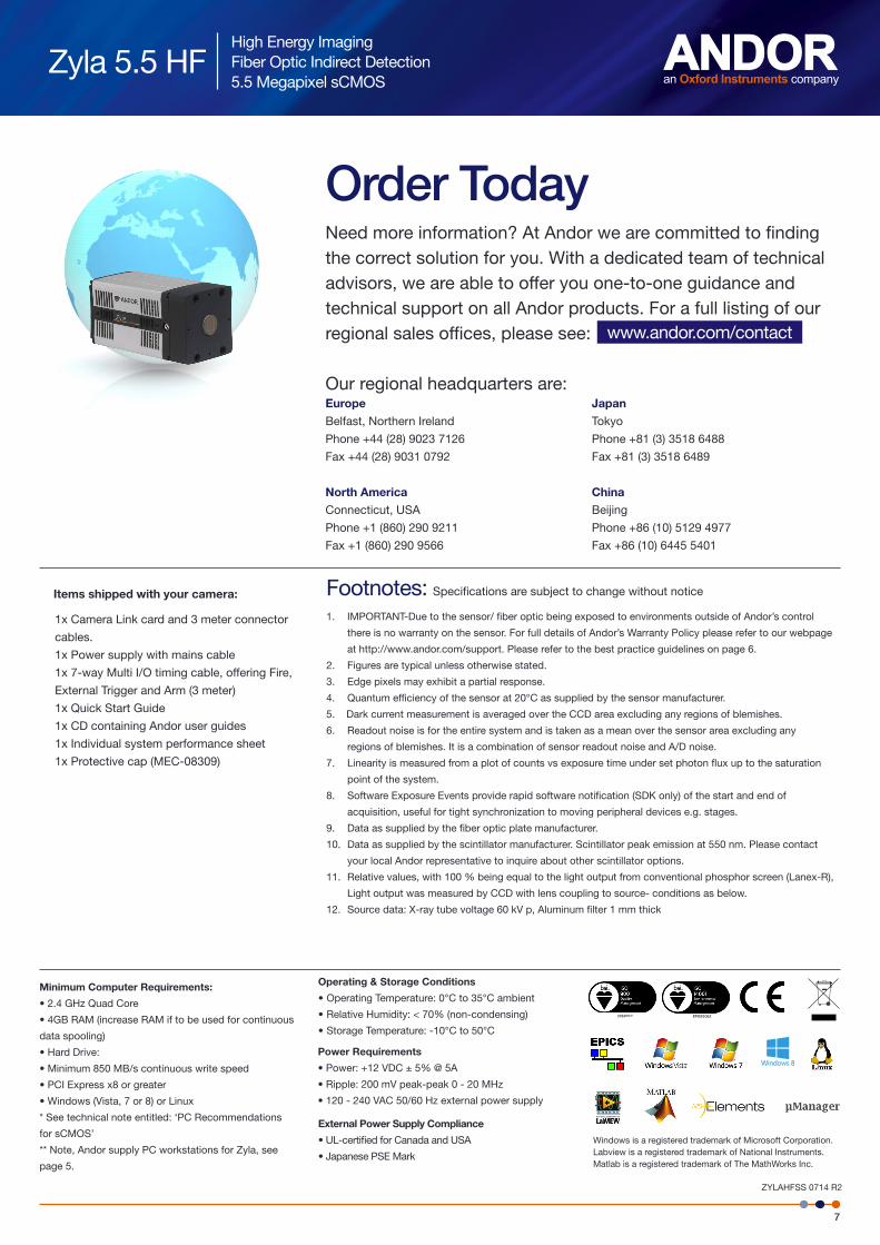
Order TodayNeed more information? At Andor we are committed to finding the correct solution for you. With a dedicated team of technical advisors, we are able to offer you one-to-one guidance and technical support on all Andor products. For a full listing of our regional sales offices, please see:
Our regional headquarters are:Europe Japan
Belfast, Northern Ireland Tokyo
Phone +44 (28) 9023 7126 Phone +81 (3) 3518 6488
Fax +44 (28) 9031 0792 Fax +81 (3) 3518 6489
North America China
Connecticut, USA Beijing
Phone +1 (860) 290 9211 Phone +86 (10) 5129 4977
Fax +1 (860) 290 9566 Fax +86 (10) 6445 5401
www.andor.com/contact
ZYLAHFSS 0714 R2
Windows is a registered trademark of Microsoft Corporation. Labview is a registered trademark of National Instruments. Matlab is a registered trademark of The MathWorks Inc.
Footnotes: Specifications are subject to change without notice
1. IMPORTANT-Due to the sensor/ fiber optic being exposed to environments outside of Andor’s control
there is no warranty on the sensor. For full details of Andor’s Warranty Policy please refer to our webpage
at http://www.andor.com/support. Please refer to the best practice guidelines on page 6.
2. Figures are typical unless otherwise stated.
3. Edge pixels may exhibit a partial response.
4. Quantum efficiency of the sensor at 20°C as supplied by the sensor manufacturer.
5. Dark current measurement is averaged over the CCD area excluding any regions of blemishes.
6. Readout noise is for the entire system and is taken as a mean over the sensor area excluding any
regions of blemishes. It is a combination of sensor readout noise and A/D noise.
7. Linearity is measured from a plot of counts vs exposure time under set photon flux up to the saturation
point of the system.
8. Software Exposure Events provide rapid software notification (SDK only) of the start and end of
acquisition, useful for tight synchronization to moving peripheral devices e.g. stages.
9. Data as supplied by the fiber optic plate manufacturer.
10. Data as supplied by the scintillator manufacturer. Scintillator peak emission at 550 nm. Please contact
your local Andor representative to inquire about other scintillator options.
11. Relative values, with 100 % being equal to the light output from conventional phosphor screen (Lanex-R),
Light output was measured by CCD with lens coupling to source- conditions as below.
12. Source data: X-ray tube voltage 60 kV p, Aluminum filter 1 mm thick
1x Camera Link card and 3 meter connector
cables.
1x Power supply with mains cable
1x 7-way Multi I/O timing cable, offering Fire,
External Trigger and Arm (3 meter)
1x Quick Start Guide
1x CD containing Andor user guides
1x Individual system performance sheet
1x Protective cap (MEC-08309)
Items shipped with your camera:
FM40523 EMS91062
External Power Supply Compliance
• UL-certified for Canada and USA
• Japanese PSE Mark