Embed Size (px)
Citation preview
INSTRUCTIONS GEK-49850A
PHASE DIRECTIONAL OVERCURRENT REL AYS WI TH VOLTAGE RES TRAINT
TYPES JBCV51M JBCV53M JBCV53M(- )YlA JBCV77M
GENERAL fj ELECTRIC www . El
ectric
alPar
tMan
uals
. com
GEK-49850
CONTENTS
PAGE
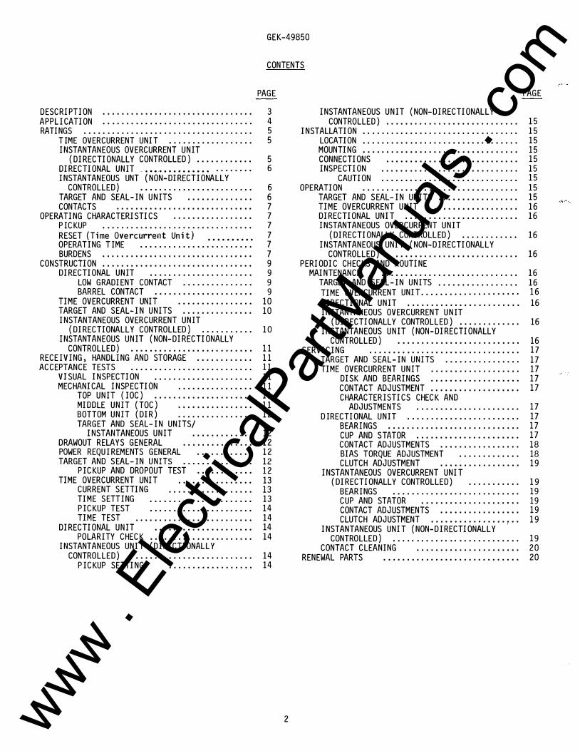
DESCRIPTION . . . . . . . . . . . . . . . . . . . . . . . . . . . . . . . . 3 APPL ICATION . . . . . . . . . . . . . . . . . . . . . . . . . . . . . . . . 4 RATINGS . . . . . . . . . . . . . . . . . . . . . . . . . . . . . . . . . . . . 5
TIME OVERCURRENT UNIT .................. 5 INSTANTANEOUS OVERCURRENT UNIT
(DIRECTIONALLY CONTROLLED) ............ 5 DIRECTIONAL UNIT -··��·········· ........ 6 INSTANTANEOUS UNT (NON-DIRECTIONALLY
CONTROLLED) . . . . . . . . . . . . . . . . . . . . . . . . 6 TARGET AND SEAL-IN UNITS .............. 6 CONTACTS . . . . . . . . . . . . . . . . . . . . . . . . . . . . . 7
OPERATING CHARACTERISTICS ................. 7 P ICKUP . . . . . . . . . . . . . . . . . . . . . . . . . . . . . . . . 7 RESET (Time Overcurrent Unit) .. .. .. .. .. 7 OPERATING TIME . .. . .. .. .. . .. .. . .. .. .. . . 7 BURDENS . . . . . . . . . . . . . . . . . . . . . . . . . . . . . . . . 7
CONSTRUCTION . . . . . . . . . . . . . . . . . . . . . . . . . . . . . . . . 9 DIRECTIONAL UNIT . .. . .. . . .. . .. .. .. .. .. . 9
LOW GRADIENT CONTACT ............... 9 BARREL CONTACT ..................... 9
TIME OVERCURRENT UNIT ................ 10 TARGET AND SEAL-IN UNITS ............... 10 INSTANTANEOUS OVERCURRENT UNIT
(DIRECTIONALLY CONTROLLED) ........... 10 INSTANTANEOUS UNIT (NON-DIRECTIONALLY
CONTROLLED) .. .. .. .. .. .. .. .. .. . .. .. . .. 11 RECE IVING, HANDL ING AND STORAGE ............ 11 ACCEPTANCE TESTS . . .. . . .. .. . .. .. .. .. .. .. .. . 11
VISUAL INSPECTION ..................... 11 MECHANICAL INSPECTION ................ 11
TOP UNIT (IOC) ..................... 11 MIDDLE UNIT (TOC) . . . • . . . . . . . . . . . . 11 BOTTOM UNIT (DIR) ................ 12 TARGET AND SEAL- IN UNITS/
INSTANTANEOUS UNIT ............. 12 DRAWOUT RELAYS GENERAL .. .. .. .. .. . .. .. 12 POWER REQU IREMENTS GENERAL ............ 12 TARGET AND SEAL-IN UNITS ............... 12
P ICKUP AND DROPOUT TEST ............ 12 TIME OVERCURRENT UNIT ................ 13
CURRENT SETTING .................. 13 TIME SETTING .. . .. .. .. .. .. .. .. . .. .. 13 P ICKUP TEST .. .. .. .. .. .. .. . .. . .. .. 14 TIME TEST . . . . . . . . . . . . . . . . . . . . . . . . . 14
DIRECTIONAL UNIT .. .. . . .. .. .. .. . .. . .. . 14 POLARITY CHECK .. .. . .. .. .. . .. . .. .. .. . 14
INSTANTANEOUS UNIT (DIRECTIONALLY CONTROLLED) ......................... 14
P ICKUP SETTING .................. 14
2
PAGE
INSTANTANEOUS UNIT (NON-DIRECTIONALLY CONTROLLED) . . . . . . . . . . . . . . . . . . . . . . . . . . . . 15
INSTALLATION . . . . . . . . . . . . . . . . . . . . . . . . . . . . . . . . . 15 LOCATION . . . . . . . . . . . . . . . . . . . . . . . . . . . . . . . . . 15 MOUNTING . . . . . . . . . . . . . . . . . . . . . . . . . . . . . . . . . 15 CONNECTIONS . . . . . . . . . . . . . . . . . . . . . . . . . . . . 15 INSPECTION . . . . . . . . . . . . . . . . . . . . . . . . . . . . . 15
CAUTION . . . . . . . . . . . . . . . . . . . . . . . . . . . . . 15 OPERATION . . . . . . . . . . . . . . . . . . . . . . . . . . . . . . . . . 15
TARGET AND SEAL- IN UNITS ................. 15 TIME OVERCURRENT UNIT ................... 16 DIRECTIONAL UNIT ........................ 16 INSTANTANEOUS OVERCURRENT UNIT
(DIRECTIONALLY CONTROLLED) ............ 16 INSTANTANEOUS UNIT (NON-DIRECTIONALLY
CONTROLLED) . . . . . . . . . . . . . . . . . . . . . . . . . . 16 PERIODIC CHECKS AND ROUTINE
MAINTENANCE . . . . . . . . . . . . . . . . . . . . . . . . . . . . . 16 TARGET AND SEAL-IN UNITS ................. 16 TIME OVERCURRENT UNIT ..................... 16 DIRECTIONAL UNIT .. .. .. . .. .. . .. . .. .. .. .. . 16 INSTANTANEOUS OVERCURRENT UNIT
(DIRECTIONALLY CONTROLLED) ............. 16 INSTANTANEOUS UNIT (NON-DIRECTIONALLY
CONTROLLED) . .. . .. .. .. .. .. .. . .. .. . . .. . 16 SERVICING . . . . . . . . . . . . . . . . . . . . . . . . . . . . . . . . 17
TARGET AND SEAL-IN UNITS ................ 17 TIME OVERCURRENT UNIT ................... 17
DISK AND BEARINGS ................... 17 CONTACT ADJUSTMENT .. . .. .. .. .. .. .. .. .. 17 CHARACTERISTICS CHECK AND
ADJUSTMENTS . . .. .. . .. .. . .. . .. .. .. . 17 DIRECTIONAL UNIT . .. . .. .. .. .. . .. . .. . .. .. . 17
BEARINGS .. .. . .. . .. .. .. . .. .. .. .. .. .. . 17 CUP AND STATOR .. .. . .. .. . .. . .. .. .. .. . 17 CONTACT ADJUSTMENTS ................. 18 BIAS TORQUE ADJUSTMENT ............. 18 CLUTCH ADJUSTMENT ................. 19
INSTANTANEOUS OVERCURRENT UNIT (DIRECTIONALLY CONTROLLED) ........... 19
BEARINGS . . . . . . . . . . . . . . . . . . . . . . . . . . . 19 CUP AND STATOR . . . . . . . . . . . . . . . . . . • . . 19 CONTACT ADJUSTMENTS ................. 19 CLUTCH ADJUSTMENT . . . . . . . . . . • . . . . . . . . 19
INSTANTANEOUS UNIT (NON-DIRECTIONALLY CONTROLLED) .. .. .. . .. .. .. .. .. .. .. . .. .. . 19
CONTACT CLEANING ...................... 20 RENEWAL PARTS . . . . . . . . . . . . . . . . . . . . . . . . . . . . . 20
www . El
ectric
alPar
tMan
uals
. com
GEK-49850
PHASE DIRECTIONAL OVERCURRENT RELAYS WITH VOLTAGE RESTRAINT
TYPES JBCV51M JBCV53M JBCV53M( - )YlA JBCV77M
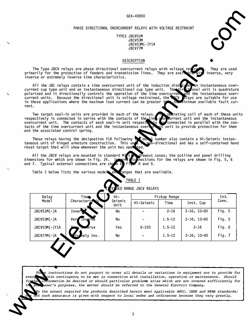
DESCRIPTION
The Type JBCV relays are phase directional overcurrent relays with voltage restraint . They are used primarily for the protection of feeders and transmission lines. They are available with inverse, very inverse or extremely inverse time characteristics.
All the JBC relays contain a time overcurrent unit of the induction disk type, an instantaneous overcurrent cup type unit and an instantaneous directional cup type unit. The directional unit is quadrature
' polarized and it directionally controls the operation of the time overcurrent and the instantaneous overcurrent units . Because the directional unit is voltage restrained, the JBCV relays are suitable for use in those applications where the maximum load current can be greater than the minimum available fault current.
Two target seal-in units are provided in each of the relays. The operating coil of each of these units respectively is connected in series with the contacts of the time overcurrent unit and the instantaneous overcurrent unit. The contacts of each seal-in unit respectively are connected in parallel with the contacts of the time overcurrent unit and the instantaneous overcurrent unit to provide protection for them and the associated control spring.
Those relays having the designation Y1A following the model number also contain a Hi-Seismic instantaneous unit of hinged armature construction. This unit is non-directional and has a self-contained hand reset target that will show whenever the unit has operated.
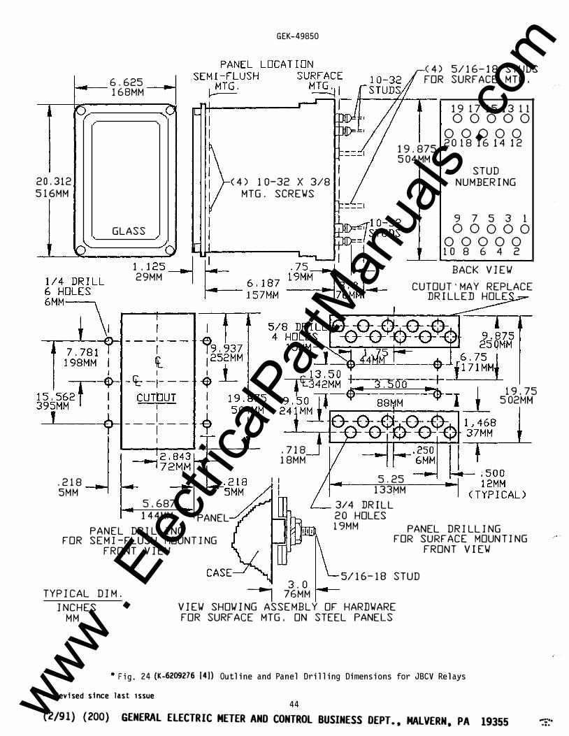
All the JBCV relays are mounted in standard M1 size drawout cases; the outline and panel drilling dimensions for which are shown in Fig . 24. Internal connections for the relays are shown in Fig . 5, 6 and 7. Typical external connections are shown by Figs. 8 and 9.
Table I below lists the various models and ranges that are available .
TABLE I
EXTENDED RANGE JBCV RELAYS
Relay Time Hi- Pickup Range Int. Model Characteristic Seismic Hi-Seismic Time Inst . Cup Conn .
Unit
JBCV51M(- ) A Inverse No - 2-16 2-16, 10-80 Fig . 5
JBCV53M {- ) A Very Inverse No - 1. 5-12 2-16, 10-80 Fig . 5
JBCV53M(- )YlA Very Inverse Yes 6-150 1.5-12 2-16 Fig . 6
JBCV77M(- ) A Extremely Inv . No - 1. 5-12 2-16, 10-80 Fig. 7
These instructions do not purport to cover all details or variations in equipment nor to provide for
e�ery possible contingency to be met in connection with installation, operation or maintenance. Should
further information be desired or should particular problems arise which are not covered sufficiently for
the purchaser's purposes, the matter should be referred to the General Electric Company.
To the extent required the products described herein meet applicable ANSI, IEEE and NEMA standards;
but not such assurarwe is given with respect to local codes and ordinances because they vary greatly.
3 www . El
ectric
alPar
tMan
uals
. com
GEK-49850
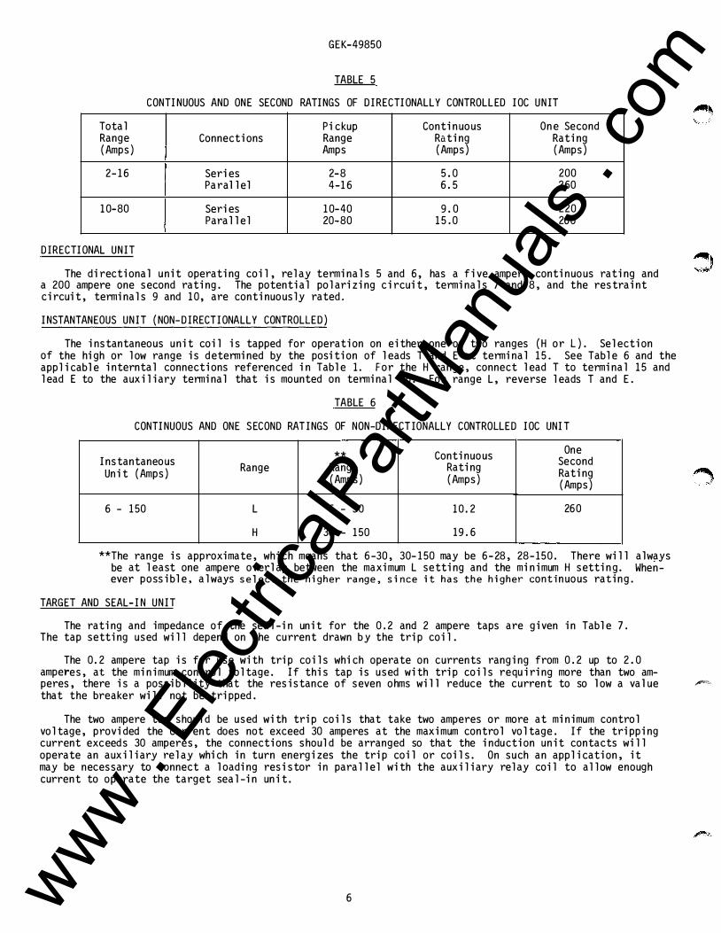
TABLE 5
CONTINUOUS AND ONE SECOND RATINGS OF DIRECTIONALLY CONTROLLED IOC UNIT
Total Pickup Continuous One Second Range Connections Range Rating Rating (Amps) Amps (Amps) (Amps)
2-16 Series 2-8 5. 0 200 Para 11 el 4-16 6. 5 260
10-80 Series 10-40 9. 0 220 Parallel 20-80 15. 0 260
DIRECTIONAL UNIT
The directional unit operating coil, relay terminals 5 and 6, has a five ampere continuous rating and a 200 ampere one second rating. The potential polarizing circuit, terminals 7 and 8, and the restraint circuit, terminals 9 and 10, are continuously rated.
INSTANTANEOUS UNIT (NON-DIRECTIONALLY CONTROLLED)
The instantaneous unit coil is tapped for operation on either one of two ranges (H or L). Selection of the high or low range is determined by the position of leads T and E at terminal 15. See Table 6 and the applicable interntal connections referenced in Table 1. For the H range, connect lead T to terminal 15 and lead E to the auxiliary terminal that is mounted on terminal 15. For range L, reverse leads T and E .
TABLE 6
CONTINUOUS AND ONE SECOND RATINGS OF NON-DIRECTIONALLY CONTROLLED IOC UNIT
** Continuous One Instantaneous Range Range Rating Second Unit (Amps) Rating (Amps) (Amps) (Amps)
6 - 150 L 6 - 30 10. 2 260
H 30 - 150 19 . 6
**The range is approximate, which means that 6-30, 30-150 may be 6-28, 28-150. There will always be at least one ampere overlap between the maximum L setting and the minimum H setting. Whenever possible, always select the higher range, since it has the higher continuous rating.
TARGET AND SEAL-IN UNIT
The rating and impedance of the seal-in unit for the 0. 2 and 2 ampere taps are given in Table 7 . The tap setting used will depend on the current drawn by the trip coil .
The 0. 2 ampere tap is for use with trip coils which operate on currents ranging from 0. 2 up to 2. 0 amperes, at the minimum control voltage . If this tap is used with trip coils requiring more than two am-peres, there is a possibility that the resistance of seven ohms wi 11 reduce the current to so 1 ow a va 1 ue """"' that the breaker will not be tripped .
The two ampere tap should be used with trip coils that take two amperes or more at minimum control voltage, provided the current does not exceed 30 amperes at the maximum control voltage . If the tripping current exceeds 30 amperes, the connections s hould be arranged so that the induction unit contacts will operate an auxiliary relay which in turn energizes the trip coil or coils . On such an application, it may be necessary to connect a loading resistor in parallel with the auxiliary relay coil to allow enough current to operate the target seal-in unit.
6 www . El
ectric
alPar
tMan
uals
. com
CONTACTS
GEK-49850
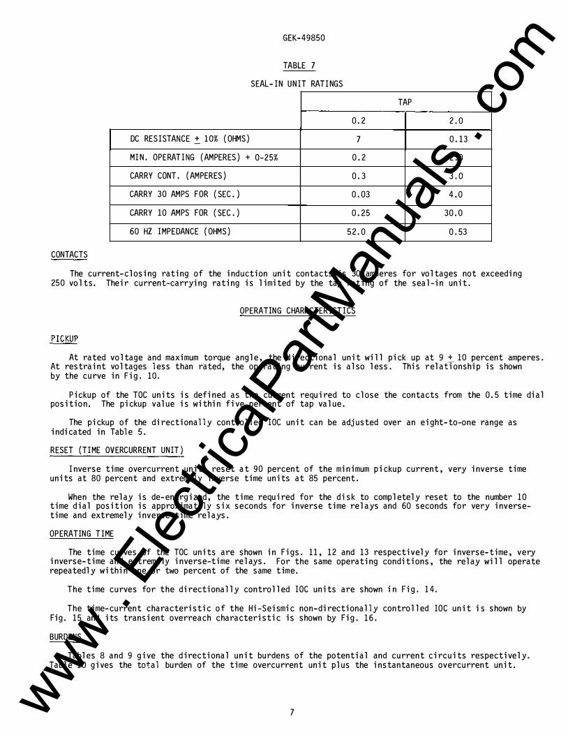
TABLE 7
SEAL-IN UNIT RATI NGS
DC RESISTANCE � 10% (OHMS)
MI N. OPERATING (AMPERES) + 0-25%
CARRY CONT. (AMPERES)
CARRY 30 AMPS FOR (SEC . )
CARRY 10 AMPS FOR (SEC. )
60 HZ I MPEDANCE (OHMS)
TAP
0. 2 2 . 0
7 0. 13
0 . 2 2 . 0
0. 3 3 . 0
0 . 03 4 . 0
0 . 25 30 . 0
52. 0 0 . 53
The current-closing rating of the induction unit contacts is 30 amperes for voltages not exceeding 250 volts. Their current-carrying rating is limited by the tap rating of the seal-in unit .
OPERATING CHARACTERISTICS
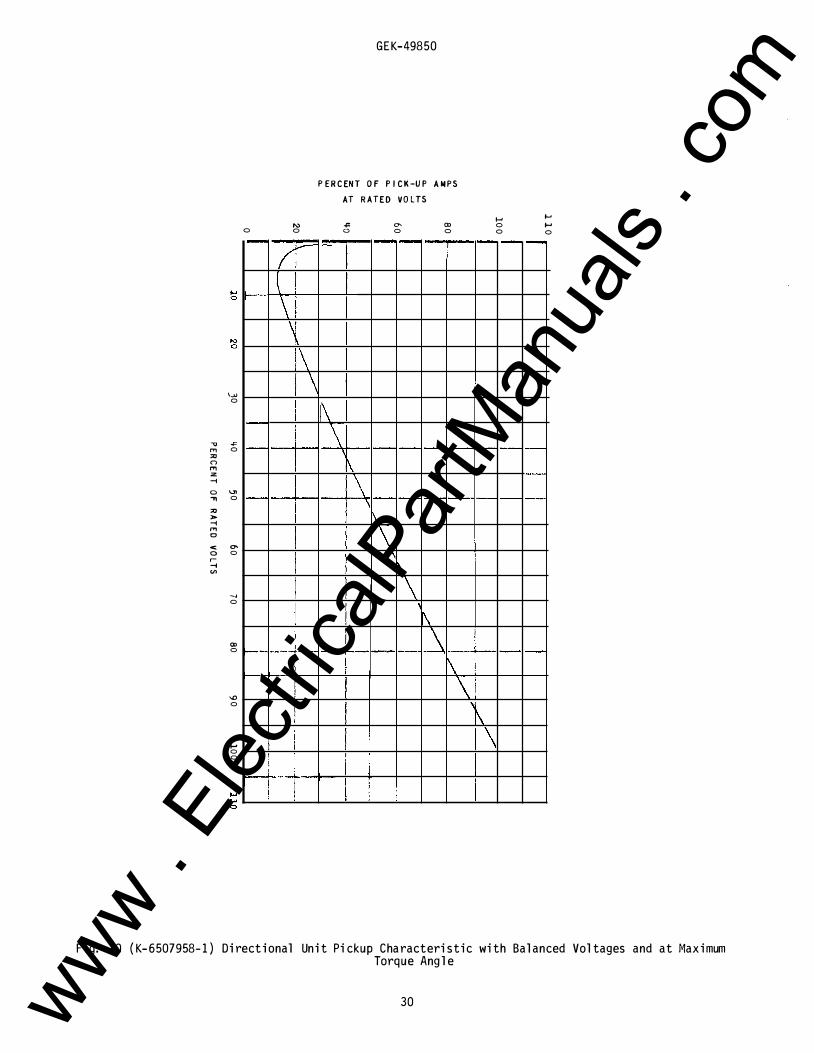
At rated voltage and maximum torque angle, the directional unit will pick up at 9 + 10 percent amperes . At restraint voltages less than rated, the operating current is also less . This relaffonship is shown by the curve in Fig. 10 .
Pickup of the TOC units is defined as the current required to close the contacts from the 0. 5 time dial position. The pickup value is within five percent of tap value .
The pickup of the directionally controlled IOC unit can be adjusted over an eight-to-one range as indicated in Table 5.
RESET (TI ME OVERCURRENT UNIT)
I nverse time overcurrent units reset at 90 percent of the minimum pickup current, very inverse time units at 80 percent and extremely inverse time units at 85 percent.
When the relay is de-energized, the time required for the disk to completely reset to the number 10 time dial position is approximately six seconds for inverse time relays and 60 seconds for very inversetime and extremely inverse-time relays.
OPERATING T IME
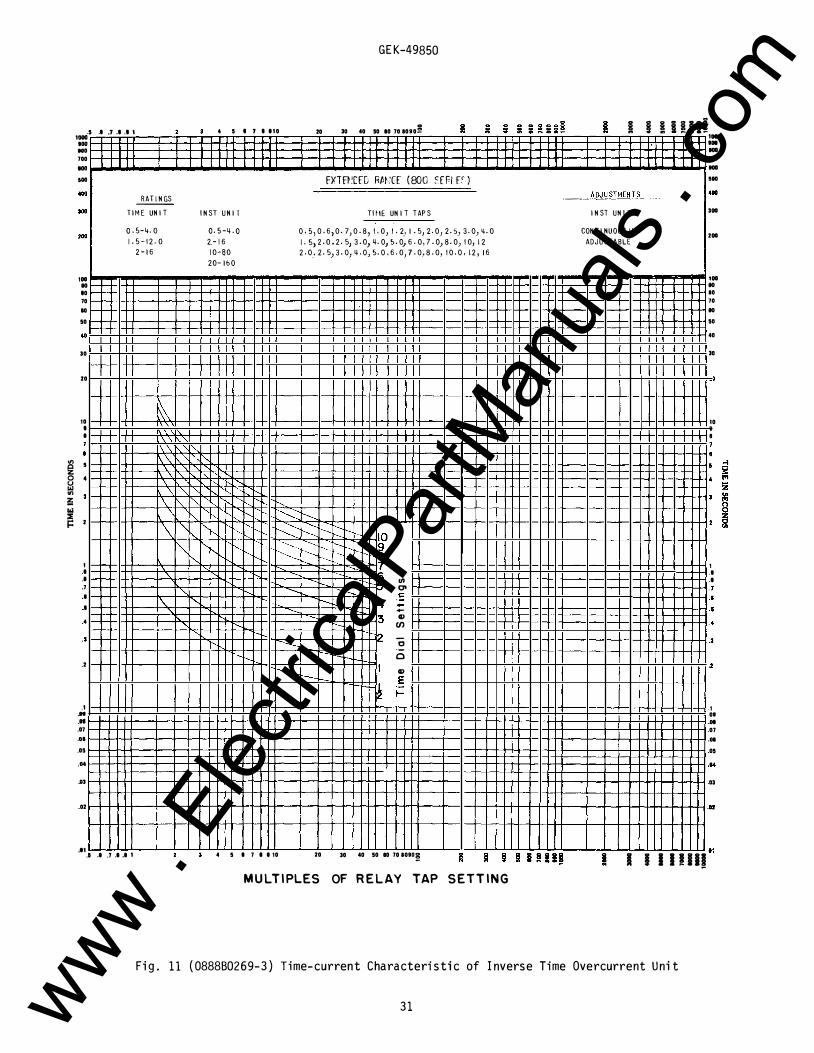
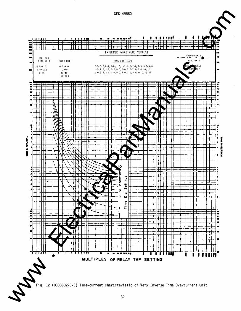
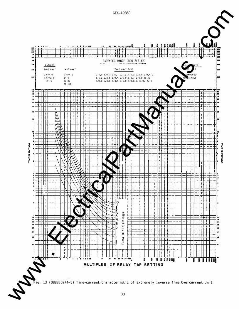
The time curves of the TOC units are shown in Figs . 11, 12 and 13 respectively for inverse-time, very inverse-time and extremely inverse-time relays . For the same operating conditions, the relay will operate repeatedly within one or two percent of the same time.
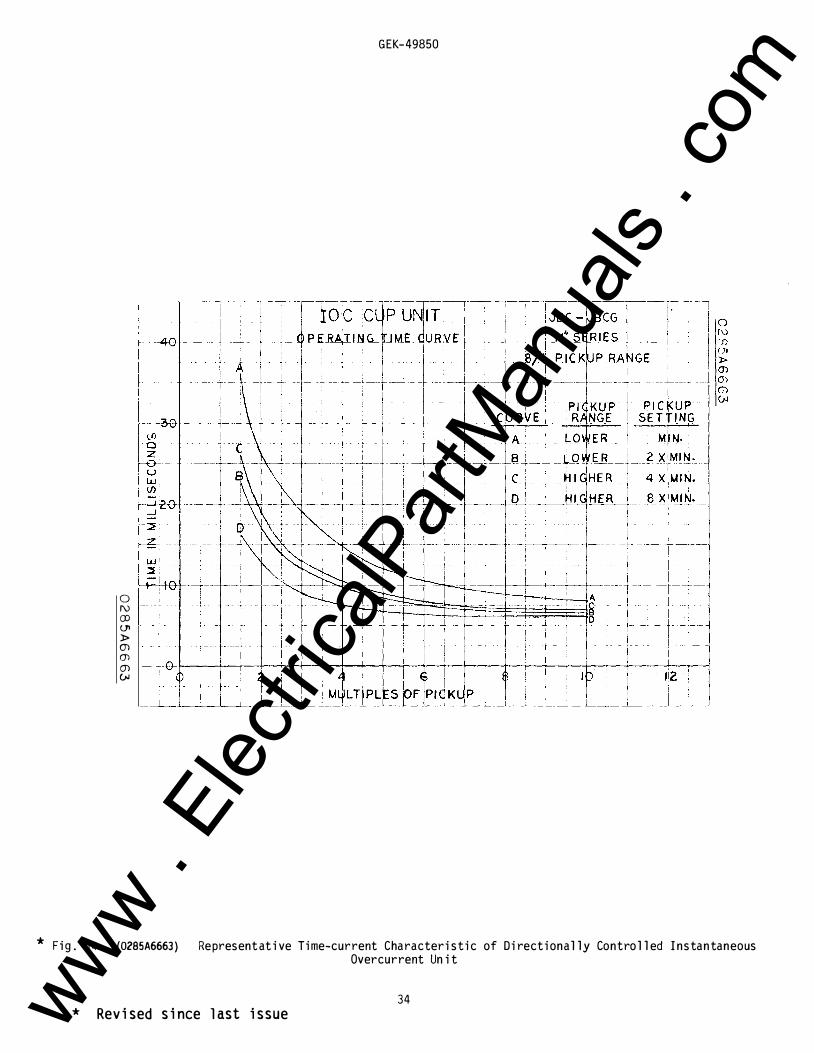
The time curves for the directionally controlled IOC units are shown in Fig. 14.
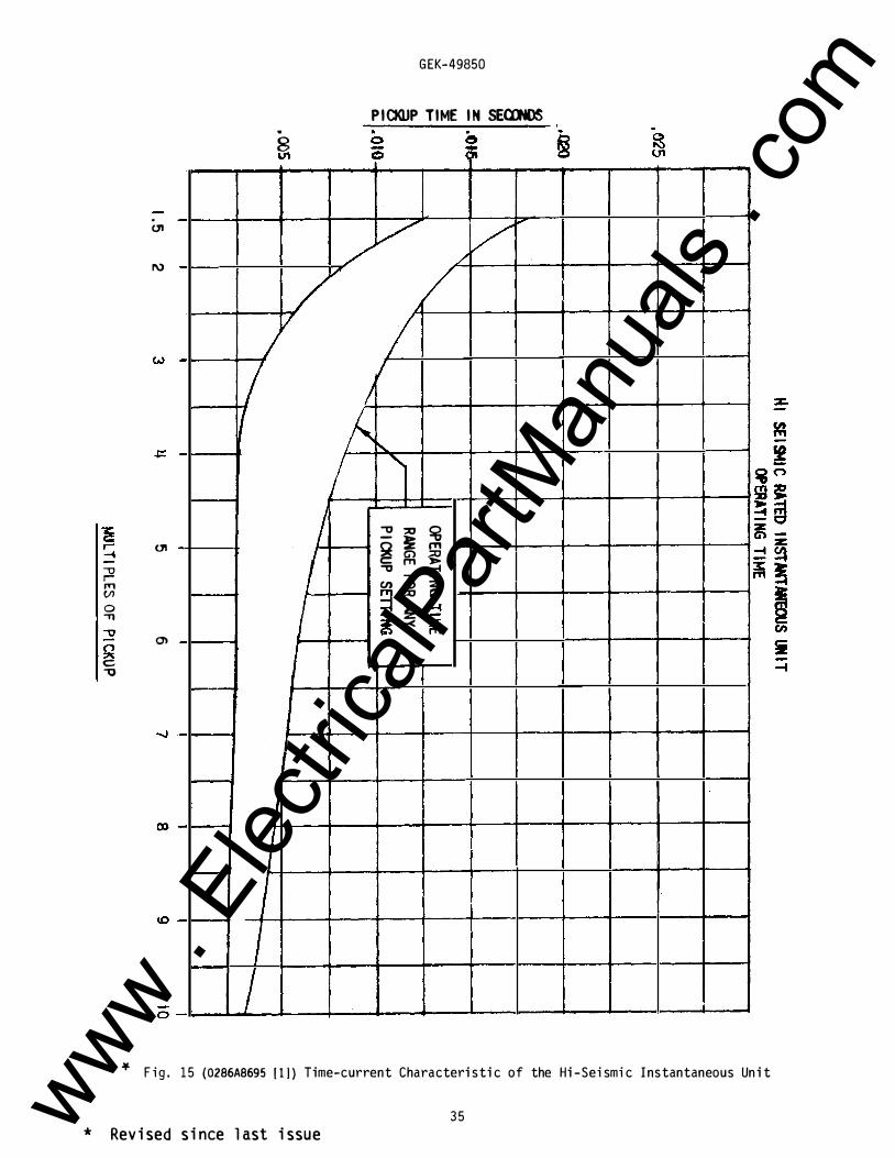
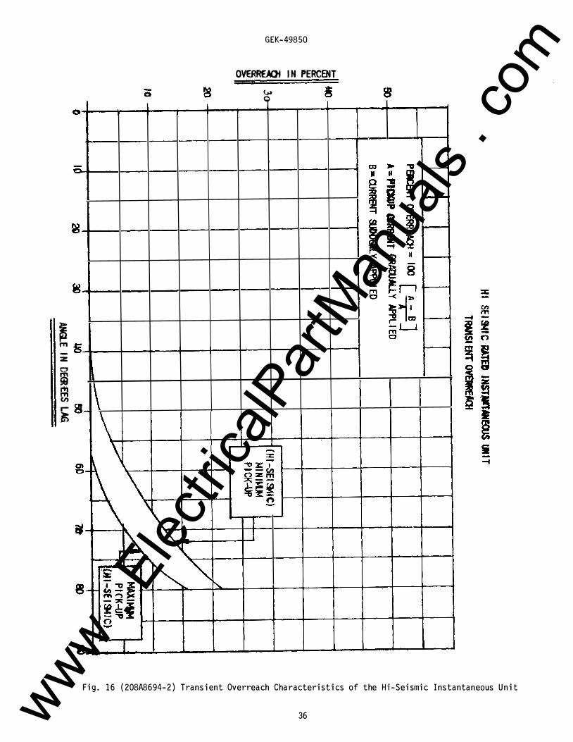
The time-current characteristic of the Hi-Seismic non-directionally controlled IOC unit is shown by Fig. 15 and its transient overreach characteristic is shown by Fig . 16.
BURDENS
Tables 8 and 9 give the directional unit burdens of the potential and current circuits respectively. Table 10 gives the total burden of the time overcurrent unit plus the instantaneous overcurrent unit.
7 www . El
ectric
alPar
tMan
uals
. com
GEK-49850
TIME OVERCURRENT UNIT
The inverse time and very inverse time overcurrent units consist of a tapped current operating coil �-wound on a U-magnet iron structure . The tapped operating coil is connected to taps on the tap bl ock. The U-magnet contains wound shading coil s which are connected in series with a directional unit contact. When power fl ow is in such a direction as to cl ose the directional u nit contacts, the shading coil s act to produce a spl it-phase fiel d which, in turn, devel ops torque on the operating disk .
The extremel y inverse time overcurrent unit is of the wattmetric type simil ar to that used in watthour meters except as fol l ows: the upper portion of the iron structure has two concentric windings on the midd l e l eg of the magnetic circuit. One of these is a tapped current winding connected to taps on the tap bl ock; the other is a fl oating winding which is connected in series with the directional unit contacts, a resistor, a capacitor and the two coil s on the l ower l egs of the magnetic circuit. When power is in such a direction as to cl ose a directional unit contact, the unit devel ops torque on the operating disk.
The disk shaft carries the moving contact which compl etes the trip circuit when it touches the stationary contact or contacts. The shaft is restrained by a spiral spring to give the proper contact-cl osing current, and its motion is retarded by a permanent magnet acting on the disk to produce the desired time characteristic . The variabl e retarding force resul ting from the gradient of the spiral spring is compensated by the spiral shape of the ind uction disk, which resu l ts in an increased driving force as the spring winds up.
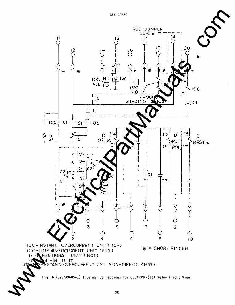
The torque control circuits of both the time overcurrent and instantaneous overcurrent units are wired to terminal s on the rel ay contact b l ock . These terminal s are shorted together by internal l y connected red jumper l eads when the rel ays l eave the factory (see Figs . 5 to 7 inc l usive). If external torque control is desired, these jumper l eads shou l d be removed.
TARGET AND SEAL- IN UNITS
The seal -in units for both the TOC and IOC contacts of the JBCV51M, JBCV53M and JBCV77M rel ays are mounted on the IOC middl e unit . On the JBCV53M(-)Y1A rel ay the right hand seal -in unit is repl aced by the non-directional l y control l ed IOC unit and the seal -in unit is moved to the l eft side of the directional ( l ower) unit.
The l eft seal -in unit operates in conjunction with the time overcurrent unit contacts and is l abel ed "TIME". Its coil is in series and its contacts in paral l el with the main contacts of the time overcurrent unit so that when the main contacts c l ose, the seal -in unit wil l pick up and seal in around the main contact.
The right seal -in unit, l abel ed "INST." operates in conjunction with the instantaneous overcurrent unit . Its coil is in series with the instantaneous unit contact and a contact of the directional unit, and its contact is connected to seal in around these two contacts when the unit operates .
Both seal -in units are equipped with targets which are raised into view when the unit operates. These targets l atch and remain exposed until manual l y rel eased by means of the button projecting bel ow the l owerl eft corner of the cover.
INSTANTANEOUS OVERCURRENT UNIT (DIRECTIONALLY CONTROLLED)
The instantaneous overcurrent unit is simil ar in construction to the directional unit described-above, differing onl y in coil turns and connections. The four corner coil s consist of two windings, an inner winding consisting of a l arge number of turns of fine wire, and an outer winding having a few turns of r
heavy wire. The outer windings of the corner coil s are connected either in series or in paral l el with the side coil s by tap l inks provided on the rel ay; these series or paral l el combinations are connected in series with the operating coil of the TOC unit. The inner windings of the corner coil s are al l connected in series, and in turn are connected in series with a capacitor and a contact of the directional unit . This circuit thus control s the torque of the instantaneous overcurrent unit. When the directional unit contacts are open, the instantaneous overcurrent unit wil l devel op no torque . When the directional unit contacts are c l osed, the instantaneous overcurrent unit wil l devel op torque in proportion to the square of the current.
The instantaneous overcurrent unit devel ops operating torque in a direction opposite to that of the directional unit. This makes the rel ay l ess susceptibl e to the effects of shock.
10 www . El
ectric
alPar
tMan
uals
. com
GEK-49850
INSTANTANEOUS UNIT ( NON- DIRECTIONALLY CONTROLLED)
This IOC unit is a smal l hinged armature type instantaneous el ement and is mounted on the right side of the TOG unit. The IOC el ement operates over a 25-to-one total range obtained by using a tapped coil which has a five-to-one l ow range and a five-to-one high range; this combination provides the 25-to-one total range . When the current reaches a predetermined val ue, the instantaneous el ement operates c l osing its contact circuit and raising its target into view. The target l atches in the exposed position until it is rel eased . The same button that rel eases the target seal -in unit al so rel eases the target of the instantaneous unit.
RECEIVING, HANDLING AND STORAGE
These rel ays, when not incl uded as part of a control panel wil l be shipped in cartons designed to protect them against damage . Immediatel y upon receipt of a rel ay, examine it for any damage sustained in transit. If injury or damage resul ting from rough handl ing is evident, fil e a damage c l aim at once with the transportation company and promptl y notify the nearest General El ectric Apparatus Sal es Office .
Reasonabl e care shoul d be exercised in unpacking the rel ay in order that none of the parts are injured or the adjustments disturbed .
If the rel ays are not to be instal l ed immediatel y, they shou l d be stored in their original cartons in a pl ace that is free from moisture, dust and metal l ic chips. Foreign matter col l ected on the outside of the case may find its way inside when the cover is removed and cause troubl e in the operation of the rel ay.
ACCEPTANCE TESTS
Immediatel y upon receipt of the rel ay an inspection and acceptance test shou l d be made to ensure �hat no damage has been sustained in shipment and that the rel ay cal ibrations have not been disturbed . If the examination or test indicates that readjustment is necessary, refer to the section on SERVICING.
These tests may be performed as part of the instal l ation or acceptance tests at the discretion of the user .
Since most operating companies use different procedures for acceptance and instal l ation tests, the fol l owing section incl udes al l appl icabl e tests that may be performed on these rel ays .
VISUAL INSPECTION
Check the namepl ate stamping to ensure that the model number and rating of the rel ay agree with the requisition .
Remove the rel ay from its case and check that there are no broken or cracked mol ded parts or other signs of physical damage and that al l screws are tight. Check that the shorting bars are in the proper l ocation( s) as shown by the internal connections diagram, Figs. 5 to 7 inc l usive and that the main brush is properl y formed to contact the shorting bar .
MECHANICAL INSPECTION
Bm.J!n i 1_llil.U
1 . The rotating shaft end pl ay shoul d b e 0 . 015-0 . 020 inch . 2. The contact gap shou l d be 0 . 028-0 . 036 inch. 3. There shoul d be no noticeabl e friction in the rotating structure . 4 . With the rel ay wel l l evel ed and in its upright position, the contact shoul d be open and resting
against the backstop .
Middl e Unit (TOG)
1 . The disk shaft end pl ay shoul d b e 0 . 005-0.015 inc h . 2 . The disk shou l d be centered in the air gaps of both the el ectromagnet and drag magnet . 3 . Both air gaps shoul d be free of foreign matter .
11 www . El
ectric
alPar
tMan
uals
. com
GEK-49850
4 . The disk should rotate freely and should return by itself to the reset position . 5 . The moving contact should just touch the stationary contact when the time dial is at the zero
time dial position .
Bottom Unit ( DIR)
1 . The rotating shaft end play should be 0 . 015-0. 020 inch . 2 . The contact gap should be 0. 015-0 . 025 inch on the low gradient front contact . 3 . The front contact should close approximately 0. 005 to 0 . 010 inch before the rear contacts .
Target and Seal-in Units/Instantaneous Unit
1. The armature and contacts should move freely when operated by hand . 2 . Both contacts should make at approximately the same time . 3. The target should latch into view just as the contacts make and should unlatch when the target
release button is operated . 4. The contacts should have approximately 0 . 030 inch wipe .
DRAWOUT RELAYS GENERAL
Since all drawout relays in service operate in their cases, it is recommended that they be tested in their case or an equivalent steel case . In this way, any magnetic effects of the enclosure will be accurately duplicated during testing. A relay may be tested without removing it from the panel by using two 12XLA13A test plugs . This plug makes connections only with the relay and does not disturb any shorting bars in the case. The 12XL�12A test plug may also be used . Although this test plug allows greater testing flexibility, it requires CT shorting jumpers and the exercise of greater care, since connections are made to both the relay and the external circuitry .
POWER REQU IREMENTS GENERAL
All alternating current operated devices are affected by freq uency . Since non-sinusoidal waveforms can be analyzed as � fundamental frequency plus harmonics of the fundamental frequency, it follows that alternating current devices ( relays) will be affected by the applied waveform .
Therefore, in order to properly test alternating current relays it is essential to use a sine wave of current and/or voltage. The purity of the sine wave ( i . e . , its freedom from harmonics) cannot be expressed as a finite number for any particular relay, however, any relay using tuned circuits, R-L or RC networks, or saturating electromagnets ( such as time overcurrent relays) is affected by non-sinusoidal wave forms .
TARGET AND SEAL- IN UNITS
The target and seal-in unit has an operating coil tapped at 0. 2 and 2 . 0 amperes .
When used with trip coils operating on currents ranging from 0 . 2 to 2 . 0 amperes at the minimum control voltage, the target and seal-in tap screw should be set in the 0. 2 ampere tap . When the trip coil current ranges from two to 30 amperes at the minimum control voltage, the tap screw should be placed in the 2 . 0 ampere tap.
The seal-in tap screw is the screw holding the right-hand stationary contact of the seal-in unit . To change the tap setting, first remove the connecting plug . Then take a screw from the left-hand s.tationary contact and place it in the desired tap. Next, remove the screw from the other tap and place it back in the left-hand contact . This procedure is necessary to prevent the right- hand stationary contact from getting out of adjustment . Tap screws should never be left in both taps at the same time.
Pickup and Dropout Test
1 . Connect relay studs 1 and 11 or 1 and 12 ( see internal connections diagram) to a DC source, ammeter and load box so that the current can be controlled over a range of 0 . 1 to 2 . 0 amperes .
2 . Close or jumper the contact(s) that parallel the seal-in unit contact . 3 . Increase the current slowly until the seal-in unit picks up. See Table 12 . 4 . Open the parallel contact circuit of step 2; the seal-in unit should remain in the picked up
position. 5 . Decrease the current slowly until the seal-in unit drops out. See Table 12 .
12 www . El
ectric
alPar
tMan
uals
. com
GEK-49850
TABLE 12
TARGET AND SEAL- IN UNIT OPERATING CURRENTS
TAP P ICKUP DROPOUT CURRENT CURRENT
0 . 2 0. 115-0. 195 0 . 05 OR MORE
2. 0 1 . 15 -1 . 95 0 . 50 OR MORE
TIME OVERCURRENT UNIT
Rotate the time dial sl ow ly and check by means of a l amp that the contacts just cl ose at the zero time dial setting.
Where the contacts just c l ose can be adjusted by running the stationary contact brush in or out by means of its adjusting screw . This screw shou l d be hel d securel y in its support.
With the contacts just cl osing at No. 0 time setting, there shou l d be sufficient gap between the stationary contact brush and its metal backing strip to ensure approximatel y 1/32 inch wipe.
CJrrent Setting
The minimum current at which the time overcurrent unit wil l c l ose its contacts is determined by the position of the pl ug in the tap bl ock. The tap pl ate on this bl ock is marked in amperes, as shown in Tabl es 2, 3 and 4.
When the tap setting is changed with the rel ay in service, the fol l owing procedure must be fol l owed: ( 1) remove the connecting pl ug; this de-energizes the rel ay and shorts the current transformer secondary winding . ( 2) remove the tap screw and pl ace it in the tap marked for the desired pickup c urrent. ( 3) Repl ace the connecting pl ug.
The minimum current required to rotate the disk sl owl y and to c l ose the contacts shou l d be within five percent of the val ue marked on the tap pl ate for any tap setting and time dial position. If this adjustment has been disturbed, it can be restored by means of the spring adjusting ring. The ring can be turned by inserting a screw driver b l ade in the notches around the edge. By turning the ring, the operating current of the unit can be brought into agreement with the tap setting empl oyed. This adjustment al so permits any desired setting to be obtained intermediatel y between the avail abl e tap settings .
Pickup adjustment by means of the control spring appl ies to the JBCV51 and JBCV53 rel ays. A different procedure appl ies to the JBCV77 rel ay . For the JBCV77 rel ay, the pickup of the unit for any current tap setting is adjusted by means of the variabl e resistor in the phase-shifting circuit. This adjustment al so permits any desired setting intermediatel y between the various tap settings to be obtained . The control spring is prewound approximatel y 660 degrees with the contacts just c l osed . Further adjustment of this setting is sel dom required; if it is required, because of insufficient range of the variabl e resistor, it should never be necessary to wind up the control spring adjuster more than 30 degrees ( one notch) or unwind it more than 90 degrees (three notches) from the factory setting.
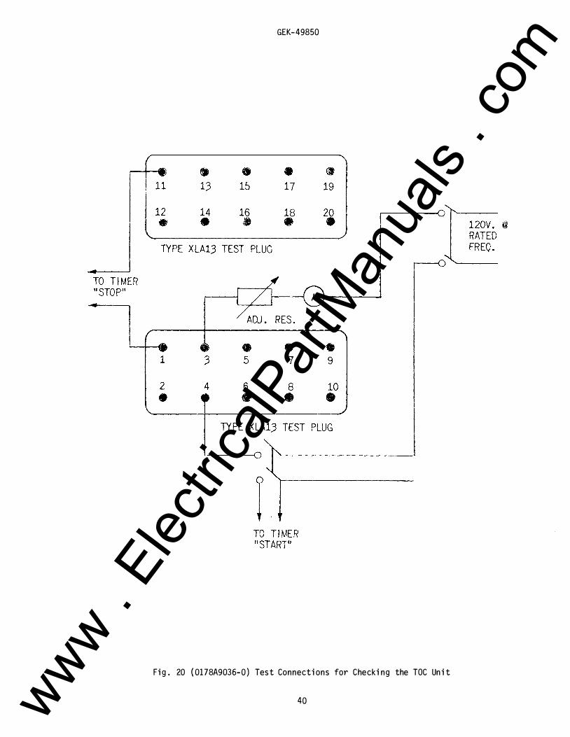
Test connections for making pickup and time checks on the time overcurrent unit are shown in Fig' . 20. Use a source of 120 vol ts or greater with good wave form and constant frequency . Stepdown transformers or phantom l oads shoul d not be empl oyed in testing induction rel ays since their use may cause a distorted wave form . The contact in the wound shading coil circuit marked D, see internal connections diagram, must be bl ocked c l osed or jumpered for both the pickup test and the time test.
Time Setting
The setting of the time dial determines the l ength of time the unit requires to c l ose its contacts when the current reaches a predetermined val ue. The contacts are just c l osed when the dial is set on zero . When the dial is set on 10, the disk must travel the maximum amount to c l ose the contacts and therefore this setting gives the maximum time setting.
The primary adjustment for the time of operation of the unit is made by means of the time dial . However, further adjustment is obtained by moving the permanent magnet al ong its supporting shel f; moving the magnet toward the disk shaft decreases the time, whil e moving it away increases the time. Be sure the magnet never extends out beyond the cutout in the disk .
13 www . El
ectric
alPar
tMan
uals
. com
GEK-49850
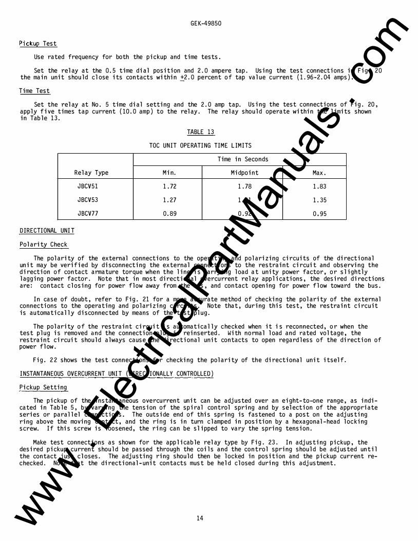
Pickup Test
Use rated frequency for both the pickup and time tests .
Set the rel ay at the 0. 5 time dial position and 2 . 0 ampere tap . Using the test connections in Fig . 20 the main unit shou l d cl ose its contacts within �2 . 0 percent of tap val ue current ( 1 . 96-2 . 04 amps).
Time Test
Set the rel ay at No . 5 time dial setting and the 2 . 0 amp tap. Using the test connections of Fig . 20, appl y five times tap current ( 10 . 0 amp) to the rel ay . The rel ay shou l d operate within the l imits shown in Tab l e 13.
TABLE 13
TOC UNIT OPERATING TIME L IMITS
Time in Seconds
Rel ay Type Min. Midpoint Max .
JBCV51 1 . 72 1 . 78 1 . 83
JBCV53 1 . 27 1.31 1 . 35
JBCV77 0. 89 0 . 92 0.95
DIRECTIONAL UNIT
Pol arity Check
The pol arity of the external connections to the operating and pol arizing circuits of the directional unit may be verified by disconnecting the external connections to the restraint circuit and observing the direction of contact armature torque when the l ine is carrying l oad at unity power factor, or sl ightl y l agging power factor . Note that in most directional overcurrent rel ay appl ications, the desired directions are: contact c l osing for power fl ow away from the bus, and contact opening for power fl ow toward the bus .
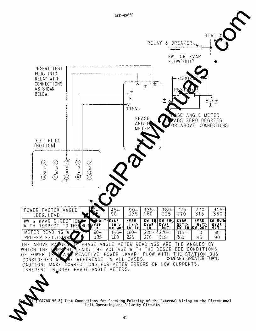
In case of doubt, refer to Fig. 21 for a more accurate method of checking the pol arity of the external connections to the operating and pol arizing circuits . Note that, during this test, the restraint circuit is automatical l y disconnected by means of the test pl ug.
The pol arity of the restraint circuit is automatical l y checked when it is reconnected, or when the test pl ug is removed and the connection pl ug is reinserted . With normal l oad and rated vol tage, the restraint circuit shou l d al ways cause the directional unit contacts to open regard l ess of the direction of power fl ow .
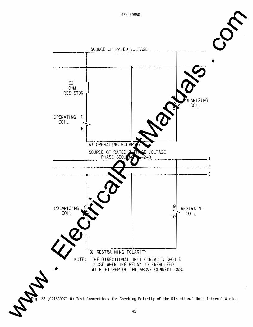
Fig. 2 2 shows the test connections for checking the pol arity of the directional unit itsel f .
INSTANTANEOUS OVERCURRENT UNIT ( DIRECTIONALLY CONTROLLED)
Pickup Setting
The pickup of the instantaneous overcurrent unit can be adjusted over an eight-to-one range, as indicated in Tab l e 5, by varying the tension of the spiral control spring and by sel ection of the appropriate series or paral l el connections. The outside end of this spring is fastened to a post on the adjusting ring above the moving contact, and the ring is in turn c l amped in position by a hexagonal -head l oc king screw. If this screw is l oosened, the ring can be sl ipped to vary the spring tension .
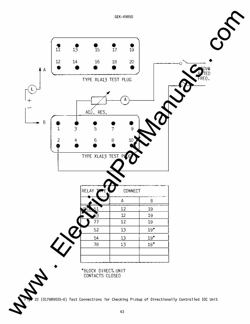
Make test connections as shown for the appl icab le rel ay type by Fig . 23 . In adjusting pickup, the desired pickup current shou l d be passed through the coil s and the control spring shou l d be adjusted until the contact just c l oses. The adjusting ring shou l d then be l ocked in position and the pickup current rechecked . Note that the directional -unit contacts must be hel d cl osed during this adjustment.
14 www . El
ectric
alPar
tMan
uals
. com
GEK-49850
INSTANTANEOUS UNIT ( NON-DIRECTIONALLY CONTROLLED)
Make sure that the instantaneous unit is in the correct range in which it is to operate. See the internal connections diagram and Tabl e 6. Whenever possibl e, use the higher range since the higher range has a higher continuous rating .
The instantaneous unit has an adjustabl e core l ocated at the top of the unit . To set the instantaneous unit to a desired pickup, l oosen the l ocknut and adjust the core. Turning the core c l ockwise decreases the pickup, turning the core countercl ockwise increases the pickup . Bring u p the current sl owl y until the unit picks up. It may be necessary to repeat this operation, until the desired pickup val ue is obtained . Once the desired pickup val ue is reached, tighten the l ocknut .
CAUTION - Refer to Tabl e 6 for the continuous and one second ratings of the instantaneous unit . Do not exceed these ratings when appl ying current to the instantaneous unit .
The range of the instantaneous unit ( See Tab le 6) must be obtained between a core position of 1/8 of a turn of ful l c l ockwise and 20 turns countercl ockwise from the ful l c l ockwise position .
INSTALLATION
LOCATION
The l ocation shou l d be cl ean and dry, free from dust and excessive vibration and wel l l ighted to facil itate inspection and testing.
MOUNTING
The rel ay shou l d be mounted on a vertical surface. The outl ine and panel dril l ing diagram is shown in Fig . 24.
CONNECTIONS
The internal connection diagrams for the various rel ays are shown in Figs. 5 to 7. Typical w1r1ng diagrams are shown by Figs . 8 and 9 . Since phase sequence is important for the correct operation of Type JBCV rel ays, the rotation specified in Figs . 8 and 9 must be adhered to. Unl ess mounted on a steel panel which adequatel y grounds the rel ay case, it is recommended that the case be grounded through a mounting stud or screw with a conductor not l ess than #12 B&S gage copper wire or its equival ent.
Terminal 12 of JBCV rel ays shou l d be connected to the negative side of the DC bus.
INSPECTION
At the time of instal l ation, the rel ay shoul d be inspected for tarnished contacts, l oose screws, or other imperfections . If any troubl e is found, it shou l d be corrected in the manner described in the section on SERVICING .
CAUTION
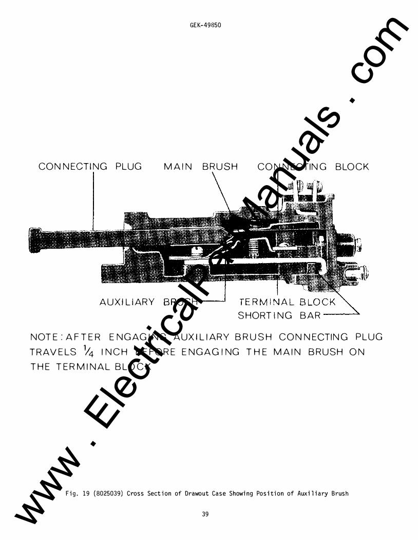
Every circuit in the drawout case has an auxil iary brush . It is especial l y important on current circuits and other circuits with shorting bars that the auxil iary brush be bent high enough to engage the connecting pl ug or test pl ug before the main brushes do. This wil l prevent CT secondary circuits from being opened. Refer to Fig . 19.
OPERATION
Before the rel ay is put into service, it shoul d be given a check to determine that factory adjustments have not been disturbed . The time dial wil l be set at zero before the rel ay l eaves the factory . If the setting has not been changed, it wil l be necessary to change this setting in order to open the time overcurrent unit contacts. The fol l owing tests are suggested:
TARGET AND SEAL- IN UNITS
1. Make sure that the tap screw is in the desired tap . 2 . Perform pickup and dropout tests as outl ined in the ACCEPTANCE TESTS section .
15 www . El
ectric
alPar
tMan
uals
. com
GEK-49850
TIME OVERCURRENT UNIT
1 . Set the tap screw on the desired tap. Using the test circuit in Fig. 20, apply approximately twice tap value current u ntil the contacts just �lose . Reduce the current u ntil the light in series with the contacts begins to flic ker . This value of current should be within five percent of tap value .
2 . Check the operating time at some multiple o f tap value . This multiple of tap value may b e five times tap rating or the maximum fault current for which the relay must coordinate . The value used is left to the discretion of the user .
DIRECTIONAL UNIT
Check directional unit polarity; see ACCEPTANCE TESTS .
INSTANTANEOUS OVERCURRENT UNIT (DIRECTIONALLY CONTROLLED) Check pickup setting; see ACCEPTANCE TESTS .
INSTANTANEOUS UNIT ( NON-DIRECTIONALLY CONTROLLED ) 1 . Select the desired range b y making the proper connections at the rear of the relay (see internal
connections diagram ) . Whenever possible, always select the higher range since it has a higher continuous rating .
2 . Set the instantaneous unit to pick u p at the desired current level . See the ACCEPTANCE TESTS section .
PERIODIC CHECKS AND ROUTINE MAINTENANCE
In view of the vital role of protective relays in the operation of a power system, it is important that a periodic test program be followed . It is recognized that the interval between periodic checks will vary depending upon environment, type of relay and the user's experience with periodic testing . Until the user has accumulated enough experience to select the test interval best suited to his individual requirements, it is suggested that the points listed below be checked at an interval of from one to two years .
These tests are intended to ensure that the relays have not deviated from their original setting . If deviations are encountered, the relay must be retested and serviced as described in this manual .
TARGET AND SEAL-IN UNITS
1 . Check that the u nit picks up at the values shown in Table 12 . 2. Check that the u nit drops out at 25 percent or more of tap value.
TIME OVERCURRENT UNIT
1 . Perform pickup test as described in the INSTALLATION section for the tap in service . 2 . Perform the time tests as described i n the INSTALLATION section .
DIRECTIONAL UNIT
Check condition and operation of contacts. A polarity check should not be necessary if it was correctly installed and no subsequent wiring changes were made.
INSTANTANEOUS OVERCURRENT UNIT (DIRECTIONALLY CONTROLLED) Check that the instantaneous unit picks up at the desired current level as outlined in the ACCEPTANCE
TEST section .
INSTANTANEOUS UNIT ( NON-DIRECTIONALLY CONTROLLED) Check that the instantaneous unit picks up at the desired current level, as outlined in the ACCEPTANCE
TESTS and the INSTALLATION TEST sections .
16 www . El
ectric
alPar
tMan
uals
. com
GEK-49850
SERVICING
These rel ays are adjusted at the factory and it is advisabl e not to disturb the adjustments . I f, for any reason, they have been disturbed or it is found during install ation or periodic testing that the rel ay is out of limits, the checks and adjustments outl ined in the following paragraphs should be observed . It is suggested that this work be done in the l aboratory .
TARGET AND SEAL- I N UNITS
Repeat the visual and mechanical inspections and the pickup and dropout current checks as outl ined in the ACCEPTANCE TESTS section.
TI ME OVERCURRENT UNIT
Disk and Bearings
The jewel should be turned up until the disk is centered in the air gaps, after which it shou l d be locked in this position by the set screw provided for this purpose . The upper bearing pin shou l d next be adjusted so that the disk shaft has about 1/64 inch end pl ay .
Contact Adjustment
The contacts should have about 1/32 inch wipe . That is, the stationary contact tip should be deflected about 1/32 inch when the disk compl etes its travel . Wipe is adjusted by turning the wipe adjustment screw thereby adjusting the position of the brush rel ative to the brush stop .
When the time dial is moved to the position where it hol ds the contacts just closed, it shou l d indicate zero on the time-dial scal e . If it does not and the brushes are correctl y adjusted, shift the dial by changing the position of the arm attached to the shaft just below the time dial . Loosen the screw c l amping the arm to the shaft and turn the arm rel ative to the shaft until the contacts just make for zero time-dial setting.
Characteristics Check and Adjustment
Repeat the portions of the ACCEPTANCE TESTS section that appl y to the time overcurrent unit . Also, check reset vol tage and time as outlined under RESET in the CHARACTERISTICS section; l ow reset vol tages or l ong reset times may indicate excessive friction caused by a worn bearing or by mechanical interference .
On JBCV77 rel ays, set the relay on the two-amp tap with the time dial set so that the contacts are just open. Adjust pickup within the l imits 1 . 96 to 2 . 04 amp but as c l ose as possibl e to 2 . 0 amps. Then move the time dial to the No. 10 position and check the current required to just move the disk away from the stop arm . This current shoul d be within the limits 1 . 88 to 2 . 12 amp . If the disk moves at the l ower l imit, check that movement is not over 1/2 inch measured along the periphery of the disk. This is cal l ed a compensation check . I f the current fal l s outside the 1 . 88 to 2 . 12 amp l imits, the fol l owing steps shou l d be taken: reset the control spring until compensation at No . 10 time dial is within l imits . Then restore pickup by adjusting the resistor. Recheck compensation after the resistor adjustment .
DIRECTIONAL UNIT
Bearings
The l ower jewel bearing should be screwed al l the way in until its head engages the end of the threaded core support. The upper bearing shoul d be adjusted to al l ow about 1/64 inch end pl ay in the shaft .
To check the c l earance between the iron core and the inside of the rotor cup, press down on the contact arm near the shaft thus depressing the spring-mounted jewel until the cup strikes the iron . The shaft should move about 1/16 inch .
Cup and Stator
Should it be necessary to remove the cup-type rotor from the directional unit, the following procedure shoul d be fol l owed:
Al l l eads to the u nit shoul d first be disconnected and tagged for identification in reconnecting. The unit can then be removed from the cradl e with its mounting plate stil l attached .
17 www . El
ectric
alPar
tMan
uals
. com
GEK-49850
The upper of the three fl at-head screws hol ding the unit to the pl ate shou l d now be removed. On some model s, it may be necessary to remove a resistor or capacitor to expose this screw. The four corner screws c l amping the unit together, shou l d next be removed, and the entire top structure l ifted off. This gives access to the cup assembl y and exposes the stator assembl y, which shoul d be protected to keep it free from dust and metal l ic particl es until the unit is reassembl ed.
To remove the shaft and rotor from the contact head assembl y, the spring c l ip at the top of the shaft must be pu l l ed out and the cl utch adjusting screw taken out of the side of the mol ded contact arm. The shaft and cup can now be pu l l ed out of the mol ding. The rotor must be hand l ed very carefu l l y whil e it is out of the unit.
Contact Adjustments
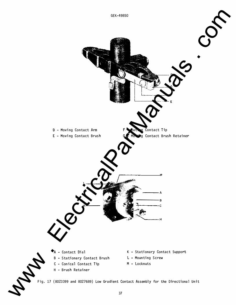
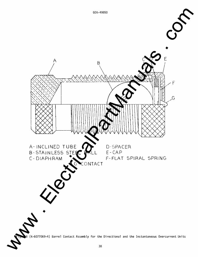
To facil itate adjustment of contacts, remove the two red jumper l eads from terminal s 18, 19 and 20 and use a neon indicating l amp in series with an AC vol tage supp l y across terminal s 18 and 19 and 19 and 20 to signify al l contact c l osures. Refer to Fig. 18 and Fig. 17 for identification of barrel and l ow gradient contact parts respectivel y and proceed as fol l ows:
Loosen sl ightl y the screw which secures the barrel backstop ( l ocated at the right front corner of the unit) to its support. This screw shou l d be onl y l oose enough to al l ow the barrel to rotate in its sl eeve but not so l oose as to al l ow the sl eeve to move within the support. Unwind the barrel backstop so that the moving contact arm is permitted to swing freel y. Adjust the tension of each l ow gradient contact brush so that one-to-two grams of pressure are required at the contact tip in order to cause the end of the brush to separate from the inner face of its respective brush retainer. Adjust the spiral spring until the moving contact arm is in a neutral position, i.e., with the arm pointing directl y forward. Loosen the l oc knut which secures the l ow gradient stationary contact mounting screw to the stationary contact support. Wind the mounting screw inward until the l ow gradient stationary_and movinq_contact members just begin to touch. Unwind the mounting screw until the stationary contact brush is vertical with the stationary contact brush retainer down. Then tighten the l oc knut which secures the mounting screw to the stationary contact support.
Loosen sl ightl y the screw which secures the barrel contact to its support. This screw shou l d be onl y l oose enough to al l ow the barrel to rotate in its sl eeve, but not so l oose as to al l ow the sl eeve to move within the support. Wind the barrel backstop in until the l ow gradient moving and stationary contact members just begin to touch. Wind the barrel contact in until the barrel contacts just begin to touch. Unwind the barrel contact one-quarter turn. Tighten the screw which secures the barrel contact to its support. Make sure that this screw is not so tight that it prevents the bal l from rol l ing freel y within the barrel . Final l y, adjust the tension on the l ow gradient stationary contact brush such that, when the l ow gradient contacts are made and fu l l y wiped in, there is approximatel y an equal defl ection on each brush.
CAUTION: When the above adjustments are compl ete, be sure to repl ace the two red jumper l eads.
Bias Torque Adjustment
The diretional unit is provided with a notched core which is used to minimize the torque produced in the rotor by current al one in the operating coil s with the pol arizing circuits de-energized. This adjustment is made at the factory and may be checked as fol l ows:
First, short out the potential pol arizing circuit. Adjust the control spring so that the moving contact structure is bal anced between the stationary contact and the stop. This can be done by l oosening the hexagonal - head l oc king screw, which cl amps the spring adjusting ring in position, and turning the ring to the l eft until the bal ance point is reached.
Energize the operating circuit with shou l d be turned in smal l steps until a The core can be turned by l oosening the by means of the sl otted bearing screw. tightened .
30 amperes and check that the contact arm does not move. The core point is reached where there is no "bias'' torque from current al one l arge hexagonal nut on the bottom of the unit and turning the core This screw shou l d be hel d securely in position when the nut is re-
Keep in mind that currents of these magnitudes wil l cause the coil s to overheat if l eft on too l ong. Therefore, l eave the test current on onl y for short interval s and al l ow sufficient time between tests for the coil s to cool .
After the torque adjustment has been made, the spiral spring shou l d be set to have barel y enough tension to swing the moving contact arm against the stop screw when the unit is de-energized. Sufficient tension wil l be obtained if the adjusting ring is rotated about one-hal f inch from the neutral position in the countercl ockwise direction, as measured on the periphery of the ring.
18 www . El
ectric
alPar
tMan
uals
. com
GEK-49850
Cl utch Adjustment
The connections shown in Fig . 22 for the pol arity check can al so be used in making the c l utch adjustment . The 50 ohm fixed resistor shou l d be repl aced with an adjustabl e resistor capabl e of providing current up to 10 amperes . A screw, projecting from the side of the moving contact arm, control s the c l utch pressure, and consequentl y, the current val ue which wil l cause the c l utch to sl ip . With rated frequency and at rated vol ts, the c l utch shou l d be set to sl ip in the range of 5.5 to 8 amperes .
The c l utch sl ip is l imited to approximatel y 20 degrees by means of a stop pin in the shaft . I t shou l d first be set to sl ip in the contact c l osing direction at the current val ues l isted in the tab l e with the pol arizing circuit energized, but with the restraint circuit open . Then check that the c l utch wil l sl ip to the l imit in the contact open�ng direction with the restraint circuit energized at rated vol ts and the current circuit open .
INSTANTANEOUS OVERCURRENT UNIT (DIRECTIONALLY CONTROLLED)
Bearings
The section BEARINGS, under DIRECTIONAL UNIT, al so appl ies to the bearings of the instantaneous overcurrent unit.
Cup and Stator
The section CUP AND STATOR u nder DI RECTIONAL UNIT, al so appl ies to the cup and stator of the lnstantaneous overcurrent unit.
Contact Adjustments
The contact gap may be adjusted by l oosening sl ightl y the screw at the front of the contact support. The screw shoul d be onl y l oose enough to al l ow tne contact barrel to rotate in its sl eeve.
The backstop screw fastened with a l ocknut shou l d hol d the moving contact arm in a neutral position, i. e. , with the arm pointing directl y forward . Then, by rotating the barrel , advance the stationary contact until it just touches the moving contact. Next, back it away 2/3 turn to obtain approximatel y 0. 020 inch gap. Last, tighten the screw which secures the barrel .
The moving contact may b e removed by l oosening the screw which secures it to the contact arm and sl iding it from under the screw head .
Cl utch Adjustment
The c l u tch on the instantaneous overcurrent unit can be adjusted by means of the screw l ocated on the right-hand side of the moving contact arm. If the l ocknut is l oosened and the screw turned in, the current at which the c l utch wil l sl ip wil l be increased . Pl ace the tap pl ugs in the l ower range taps ( series) . Hol d the directional uni·t contacts cl osed . Adjust the c l utch so that the current at which the cup just starts to sl ip fal l s within the l imits l isted in Tab l e 14.
TABLE 14
DIRECTIONALLY CONTROLLED IOC UNIT CLUTCH ADJUSTMENT
Suddenl y Appl ied Current Suddenl y Appl ied Current Pickup Range Cl utch Must Not Sl ip ( Amps) C lutch Must Sl ip ( Amps)
2-8 12 15 10-40 44 58
Note that too freq uent or too l ong appl ication of these currents wil l overheat the coil s
INSTANTANEOUS UNIT ( NON-DIRECTIONALLY CONTROLLED)
1. Both contacts shou l d c l ose at the same time .
2 . The backing strip shou l d be so formed that the forked end ( front) bears against the mol ded strip under the armature .
19 www . El
ectric
alPar
tMan
uals
. com
GEK-49850
3. With the armature against the pole piece, the cross member of the "T" spring shou l d be in a horizontal pl ane and there shou l d be at l east 1/64 inch wipe on the contacts . Check this by inserting a 0. 010 inch feeler gage between the front half of the shaded pole with the armature held c l osed. The contacts shou l d c l ose with the feel er gage in pl ace.
CONTACT CLEANI NG
For cl eaning fine sil ver contacts, a flexibl e burnishing tool shou l d be used. This consists of a flexibl e strip of metal with an etched roughened surface, resembling in effect a superfine fil e . The polishing action is so delicate that no scratches are l eft, yet corroded material wil l be removed rapidl y and thoroughl y. The flexibility of the tool insures the c l eaning of the actual points of contact.
Fine silver contacts should not be c l eaned with knives, fil es or abrasive paper or c l oth. Knives or fil es may l eave scratches which increase arcing and deterioration of the contacts. Abrasive paper or cloth may leave minute particles of insul ating abrasive material in the contacts thus preventing contact closing.
The burnishing tool described above can be obtained from the factory.
RENEWAL PARTS
It is recommended that sufficient quantities of renewal parts be carried in stock to enable the prompt repl acement of any that are worn, broken, or damaged.
When ordering renewal parts, address the nearest Sal es Office of the General El ectric Company, specify quantity required, name of part wanted, and give compl ete namepl ate data. If possibl e, give the General Electric Company requisition number on which the rel ay was furnished. Refer to Renewal Parts Publication GEF-4090.
20 www . El
ectric
alPar
tMan
uals
. com
GEK-49850
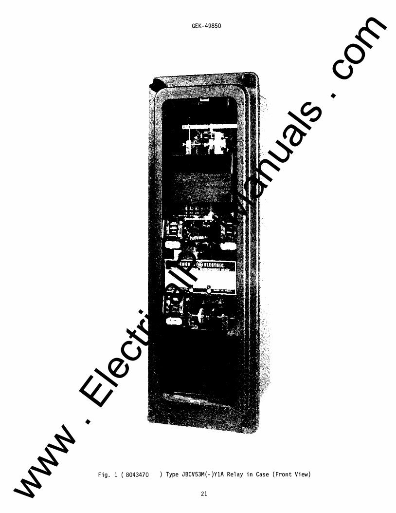
Fig . 1 ( 8043470 ) Type JBCV53M( - )Y1A Rel ay i n Case ( Front View)
21 www . El
ectric
alPar
tMan
uals
. com
GEK-49850
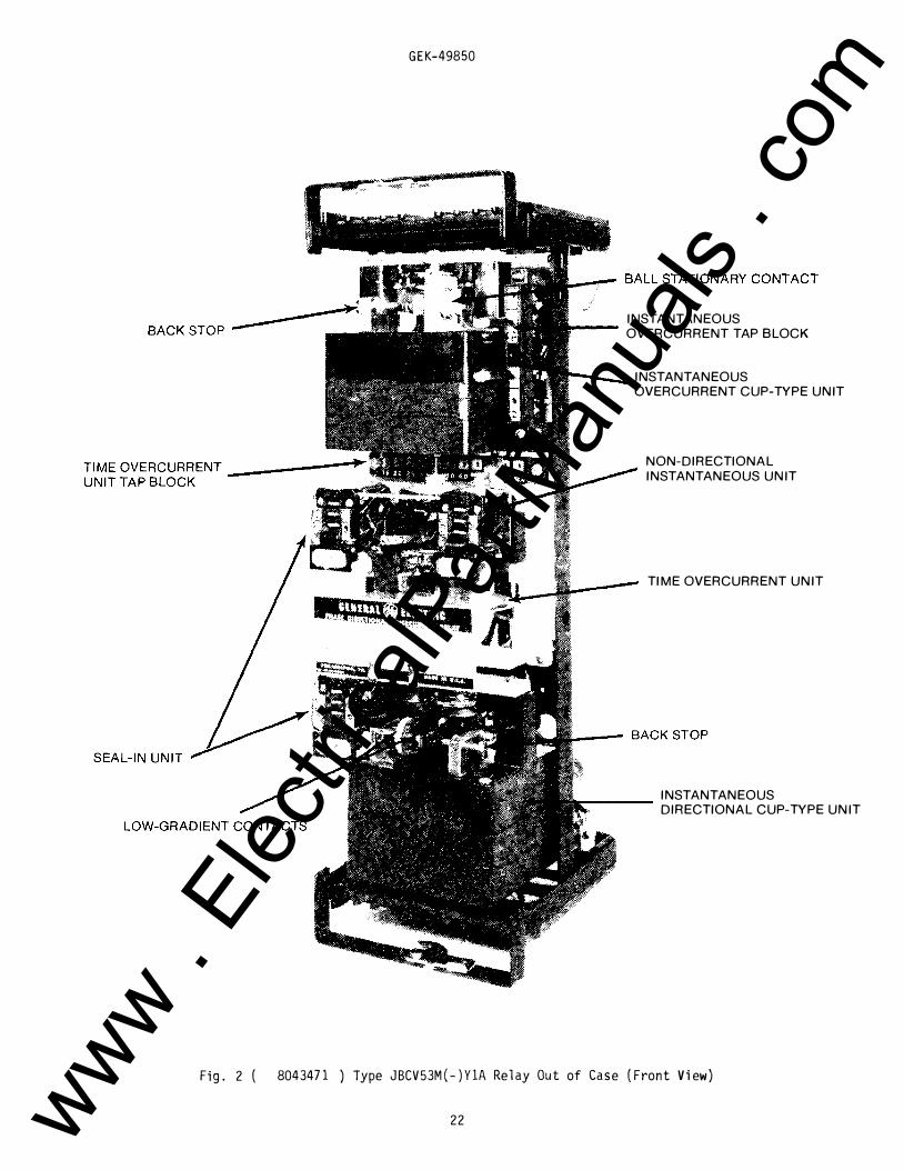
INSTANTANEOUS --- OVERCURRENT TAP BLOCK
INSTANTANEOUS
OVERCURRENT CUP-TYPE UNIT
NON-DIRECTIONAL
INSTANTANEOUS UNIT
TIME OVERCURRENT UNIT
INSTANTANEOUS r----
DIRECTIONAL CUP-TYPE UNIT
Fig. 2 ( 8043471 ) Type JBCV53M(-)YlA Relay Out of Case (Front View)
22 www . El
ectric
alPar
tMan
uals
. com
GEK-49850
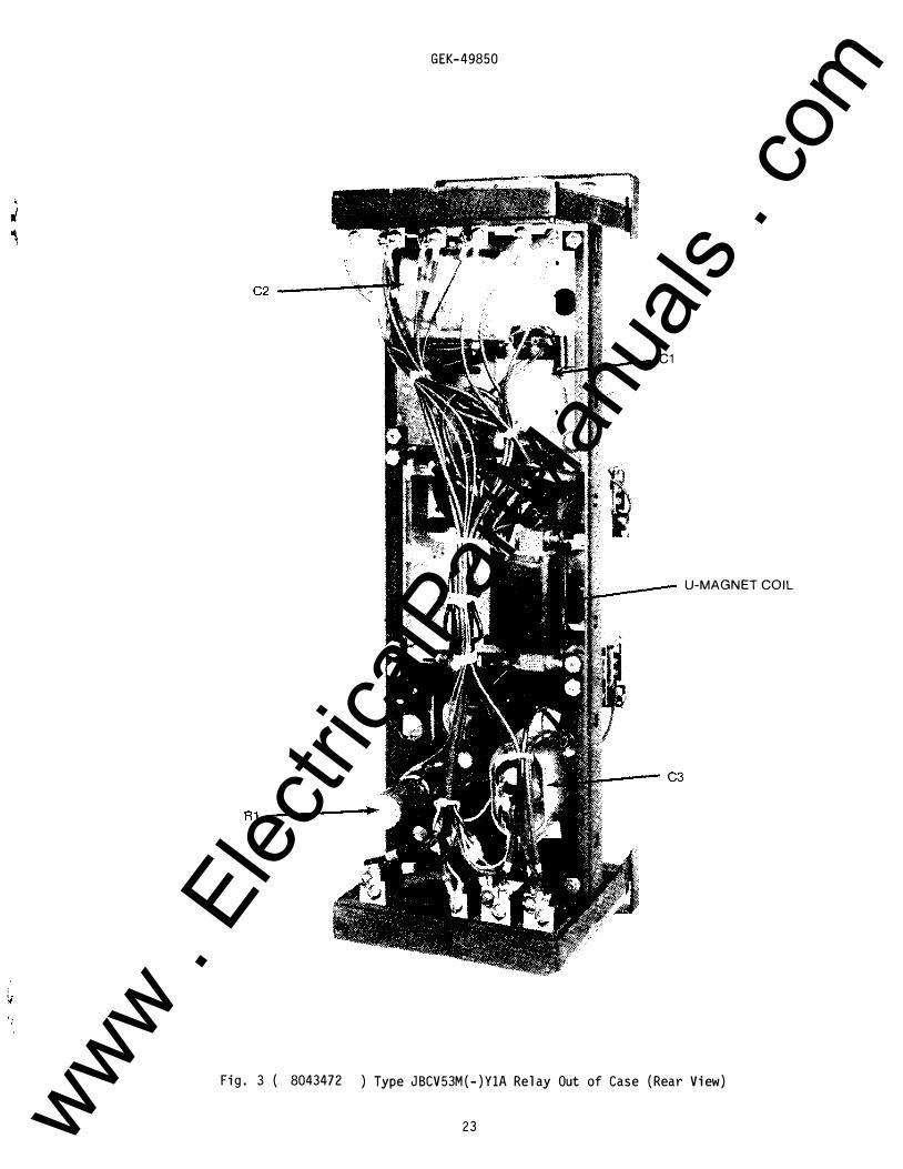
C1
U-MAGNET COIL
Fig. 3 ( 8043472 ) Type JBCV53M(-)Y1A Relay Out of Case (Rear View)
23 www . El
ectric
alPar
tMan
uals
. com
GEK-49850
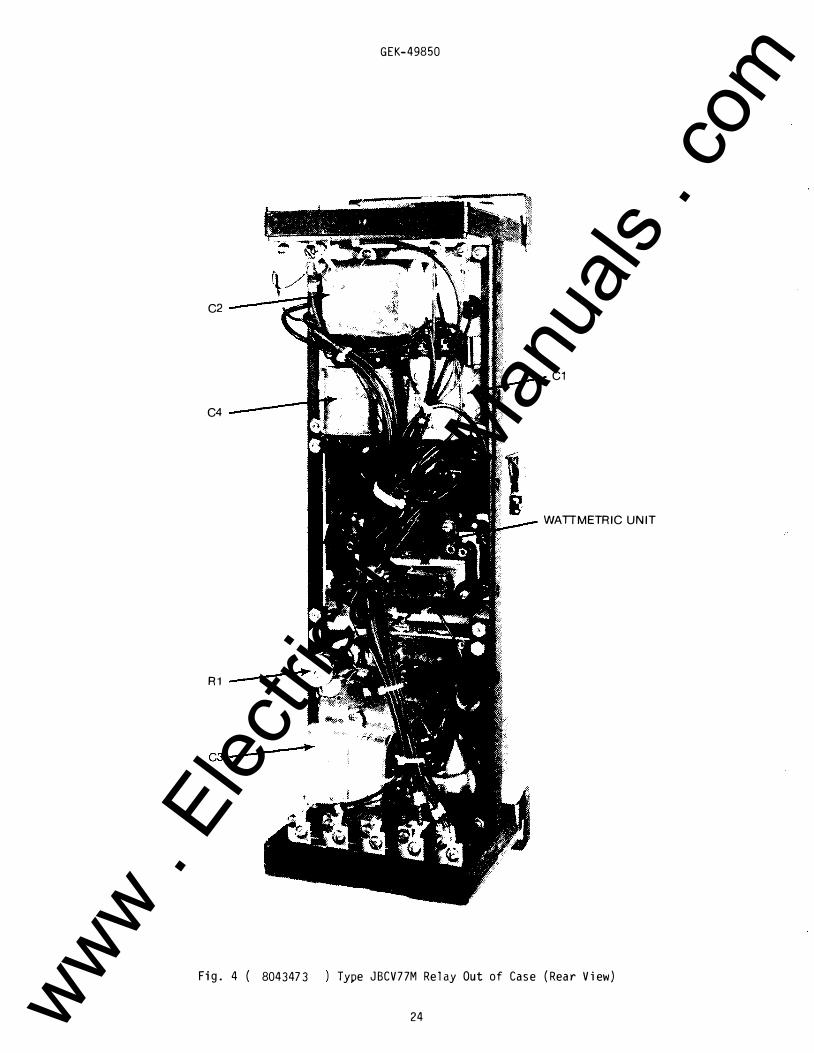
C2
C1
C4
WATIMETRIC UNIT
R1
Fig. 4 ( 8043473 Type JBCV77M Relay Out of Case (Rear View)
24 www . El
ectric
alPar
tMan
uals
. com
II
12
1 *
GEK-49850
RED JUI'APFR LEADS
18
1 19 r
I J 20
) ?oc
�� -
�
------------��W--
0-U
-�-
C-.. �
IOC
PI
j_ TCC Sl
2
\...
SHADING CC·ILS
Sl IOC
Sl
3
0 C2
OPER. cr
roc
4
'[ u s 7
I I I
Rll I L
8
.-L , -r-L I I
USED
0 D POT. RES TR.
PI POL P4.
9
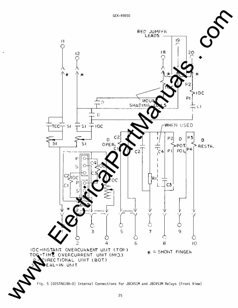
10 IOC-INSTANT. OV E RCU R f.< E NT UhiT CTOP>
TOC -TIME OVERCURRENT Ut!IT <t-11 J.) * = SHOf\T FINGEh
0 - 0 I RECTI 0 NA L U t,ll T t 8 0 T) S I- SEAL-IN Uhl T
Fig. 5 (0257A6198-0) Internal Connections for JBCV51M and JBCV53M Relays (Front View)
25 www . El
ectric
alPar
tMan
uals
. com
r r
I 12
� *" I *
GEK-49850
IS
roc
REO JUMPER
C2
LEAD S ---.--1 9-...., 17
-- \V
r 3 5
2 4 IOC -INSTANT. OVERCURRENT UNIT r TOP>
TOC -TIME OVERCURRENT UNIT (MID,) D- DIRECTIONAL Uh'T (BOT,>
Sl- SEAL -IN UNIT
7 9
8
*=SHORT FINGER
IOl.-N.D-tNSTANT. OVERCU:.RENT : .. 'NIT NON-DIRECT. (MID.>
roc
10
0 RESTR,
Fig. 6 (0257A9685-1) Internal Connections for JBCV53M(-)YlA Relay (Front View)
26 www . El
ectric
alPar
tMan
uals
. com
tl
12
A • •
TOC Sl Sl
S l
•
t I
GEK-49850
REO .JUMPt:l' LEADS
TOC WOUN� SHAOI G
COILS
�-�r 0 C4
C2 0 1 OPfR. cr
C2
TOC
_l r 5 7
t9
9
•
IOC
Cl
D RESTA.
2 4 6 8 tO tO C -INSTANT. OI!RCURHNT UN&T CTOP l TGC - TtM£ OYIRCUAHNT UtiT CM4 OJ
D .. OIAICftOMM. UNIT C.IOT.) S I .. SEAl-IN UNIT
• : $HOAT FlN6EA
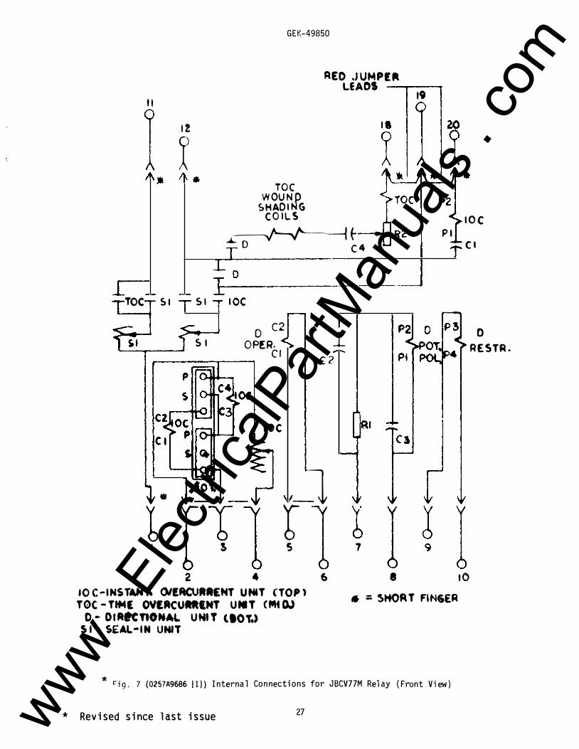
* �ig. 7 (0257A9686 (1)) Internal Connections for JBCV77M Relay (Front View)
* Revised since last issue 27 www . El
ectric
alPar
tMan
uals
. com
3 2 1 NOTE: RELAY
OPERATES FOR
FAULTS IN
DIRECTION OF
ARROW.
GEK-49850
TRIP BUS (+)------�-----------------------------
-a
52 TC
I I I
SIMILAR CIRCUITS
FOR OTHER TWO
RELAYS
1 t 1 (-)------�----------------------------
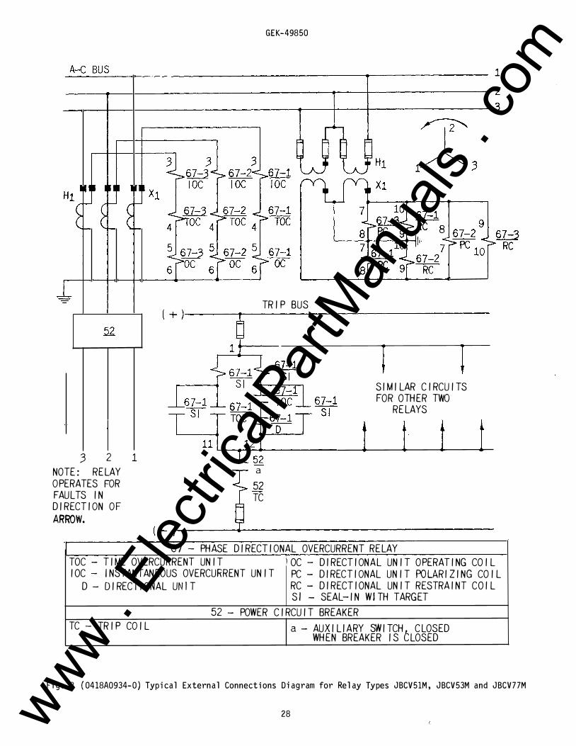
67 - PHASE DIRECTIONAL OVERCURRENT RELAY
TOC- TIME OVERCURRENT UNIT OC - DIRECTIONAL UNIT OPERATING COIL
IOC- INSTANTANEOUS OVERCURRENT UNIT PC- DIRECTIONAL UNIT POLARIZING COIL
D- DIRECTIONAL UNIT RC- DIRECTIONAL UNIT RESTRAINT COIL
Sl - SEAL-IN WITH TARGET
52- POWER CIRCUIT BREAKER
TC - TR I P CO I L a- AUXILIARY SWITCHt CLOSED WHEN BREAKER IS LOSED
Fig. 8 ( 0418A0934-0) Typical External Connections Diagram for Relay Types JBCV51M, JBCV53M and JBCV77M
28 www . El
ectric
alPar
tMan
uals
. com
-
1
GEK-49850
------�------------------------------�-------------- 1 --��1---------------------------,---�-------------- 2 ���1-----------------------�--1---�-------------- 3
G7 -3 1 4 ro 7 -2 1 4 1 5 roc 1 5 roc 1 5
N.D. N.D.
3 3 3
X I
(+)
5 2
I � 6 7- 1 1 7 ro c
N D
3 2
G 7- 1 lOC N.D.
5 7- I roc 67- 1 TO C
G 7- l D
G 7- l sr
G7- l TO C
? 1 � 3
67- 1 RC 8
'-----i---+-tlll
G ?- 1 �
(D 7- 1
I IO C
G?- 1 D
67-27 R C
6 7- 1 S I
NOTE: RELAY OPERATES FOR FAU LTS I N D I RECT I O N A R ROW.
O F
52 T 52 T C
1 2
C O N NECT PHASE 2 A ND P H ASE 3 RELAYS S I M I L AR LY ..
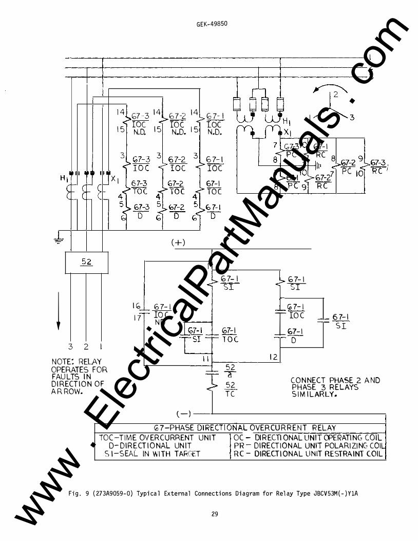
(-) G ? -PHASE D I RECTI ONAL OVER CU R R EN T R ELAY
TOC -T I M E OV ER CURRENT U N I T OC - DI R ECTI ONAL UNIT CPERATI NG COIL D- D I R E CT I O NAL UN IT PR - DI RECT I O N AL UNIT POLARI ZI NG COIL
S I -SEAL IN W I TH TARCtT R C - D IRECT I ONAL UNIT RESTRA INT COIL
Fi g . 9 (273A9059-0) Typical External Connections Diagram for Rel ay Type JBCV53M(-)YlA
29 www . El
ectric
alPar
tMan
uals
. com
-, "' "' ("") ,.,., z -i 0 ., "' > -i "' 0 < 0 r -i (/)
'-" 0
""' 0
U> 0
"' 0
..... 0
()) 0
"' 0
f-' 0 0
GEK-49850
P ER C EN T O F P I C K -U P A N PS
.., 0 0
If r--- \
\ \
1\ \
r--- --
1---t--
I
I I
�--r--i !
AT
4= 0
\ \
1\
1-- i
R AT E D VO LTS
"' ()) 0 0
\ \ \ i l
\ \
1\ \
i . ;
1\ \ I
1\ '
i f
f-' f-' 0 f-' 0 0
' --
\
Fig. 10 (K-6507958-1) Directional Unit Pickup Characteristic with Bal anced Vol tages and at Maximum Torque Angl e
30 www . El
ectric
alPar
tMan
uals
. com
0 0
1000 ... .. 70
... ... ... ...
0 0
100 .. I 7
..
50
40
30
20
10 • I
� . 0 • � "' 15 � 2
1 .I .I .7
.I
•
.. •
.2
.1 ... ... .07
.01
. 05
...
... .02
. 11
5 • 7 • • 1 . . .
R AT I N GS ---T I M E UN I T
Q . 5-4. 0 1 . 5 - 1 2 . 0
2 - 1 6
� ,\.. .\ .\.
'\ 1"-" \ "'
\ "
�
" 1\.
.1 .I .7 .I .I 1
GEK-49850
0 4 5 • 7 • 110 20 30 40 50 80 70 1090�
FXTfl:cEu RM:CE' (BOG �Hi r: )
I N ST U N I T TH1E UN I T T AP S
Q . 5 -4 . Q o . s, o . 6, o . 7, o . a, 1 . 0, 1 . 2, 1 . 5, 2 . o, 2 . 51 3 . o, 4. o 2 - 1 6 1 . s, 2 . 0 , 2 . 5, 3 . 0, 4. o, s . o, 6 . o, 7 . o, a . o, 1 0, 1 2 1 0-80 2 . o, 2 . 51 3 . o, 4 . o, s. o . 6 . 0, J . o, a . o, 1 o . o , 1 2 , 1 6
20- l b O
l" l',['_
I'-�
""
......
......
['-"' �' ""�"- ,.....
['-
I'--
""" � � . :-----.
-:-----....._
.___
....._..__
--...___
4 5 I 7 I I 10
:-----. ---::: .___
.___ -.___
"- . .___
.___
r---
20
....._ "-., 10 ....._ 9 8
7 6 "'
01 c:
4 --3 Q)
.._ en
2 c ·-
t--r-- 0 I Q) E � 1-
30 40 50 80 70 1090!
M U LT I PLES OF R E L AY TAP S E T T ING
I § ! H U�
·-- A DJ U STMEHlL . .
I N ST UN I T
CON T I NUOUS LY ADJ U STABLE
I I I I Ull
Fig . 1 1 (088880269-3) Ti me- current Characteri stic of I nverse Ti me Overcurrent U nit
31
1 ... ... .... 700
....
... ... 300
200
1 00 .. 10 70
..
50
40
30
..
10 • •
1 • I
1 01 .. 07
..
05 .. 03
..
11
www . El
ectric
alPar
tMan
uals
. com
1110 ... ... 711 ... -
...
-
101 .. .. 7 ..
I
..
..
..
I I I 7 I I
•
I
2
1 I I 7 I I
•
I
2
1
I 7
.n .. .. ... ...
..
.n
.n
I I 7 I I 1 . . .
RAHNGS
T I ME UN I T
Q . 5-�. 0 1 - 5- 1 2 . 0
2- 1 6
�\\ �\� �\\\1 �
\
1 \ \
1\
.I .7 .I .1 1
GEK-49850
4 I I 7 I 111 . . .. .. .. ,. .. ... - I I I I I ! 1 11 -
I I 1 1 l i T I I EXTE�:DEC F'��U ( 800 <- I'R I E�)
I � ST UN I T T H-1E UN I T TAPS
Q , 5-4 . 0 2 - i 6
1 0 -80 20- 1 6 0
� .\\
,\ (\\ \\
\ t\' \ \
\ \ \
\ [\I\
1 \ \
a. s, o . 6, o . 7, o . s , 1 . a, 1 . 2, 1 . s_. 2 . 0, 2 - 5, 3. o, 4. o 1 - 5, 2 - 0, 2 - 5, 3 - 0 , 4. 0, 5 . 0 , 6 . 0, 7 . 0, 8 . 0_, 1 0, 1 2
2 . 0_, 2 . 5, 3 . 0 , 4 - 0 , 5. 0, 6 . 0, 7 . 0 , 8 . 0, 1 0 . 0_, 1 2_. 1 6
.
1-·-'- '-
1'-._ -"·t'--t'\r--.
r, -� r-..."- � f::::: 1--\ !-., t'----: 1- 10 ....... 1-.. 9
- 8 ......... r-:::: 7 "' r----... ...... 1--. 6 11:11
5 c -
- 4 -
r- • C/) 1"'--- 3
......... t-- Ci " 2 0
"'" r- •
f--.t- E ·-I t-
1 2
4 I I 7 I 1 11 II • • .. " '"""! I I I I I I! Ill M U LT I P L E S OF RELAY TAP S E T TING
I I I 1 1 1 1 11 -
ADJ U STI� EN T S
I N S T . U N I T
CON T I N UO U S LY
A UJ U ST A B L E
1111 ... ... 711 ... ...
-
-
,..
111 .. .. 71 .. ..
..
..
JO
11 I I f I I :I • 15 i
I I 1 I I
..
..
.2
1 .. .. i7 .. ...
..
..
I I I r l l llf'
Fig . 12 (088880270-3) Time-current Characteristic of Very Inverse Time Overcurrent Unit
32 www . El
ectric
alPar
tMan
uals
. com
1000 ... 10 700
0
.. 0
...
...
30 0
20 0
0 0 0
100 • • 7
.. 0
..
0
..
0 • • 7
•
2
1 I • 7
I •
•
•
2
1 • • 7
• 0 . 0 .0
..
. 0
•
•
...
...
.02
.01
GEK-49850
0 5 I 7 I I 1 . . . 4 I I 1 I 110 20 30 40 50 10 701010a - � -
EXTE�'CED f1�NGF ( 800 �H I ES l � T I M E UN I T I � ST. UN I T T I M E UN I T TAPS
o. 5-�. 0 Q. 5-�. 0 o . s, o . 6, o . ?, o . a, 1 . 0, 1 . 2, 1 . 5, 2 . 0, 2 . 5, 3. o, 4. 0 1 . 5- 1_2 . 0 2- 1 6 1 . 5, 2 . 01 2 . 5, 3 . o, 4. 0, 5 . o, 6 . o, ? . o, a . o , 1 0 , 1 2
2 - 1 5 1 0 -80 2 - 0, 2 . 5, 3 . o . � . o, 5 . 0 , 6 . o, ? . o,. s . o, 1 o . o, 1 2, 1 5 20- 1 60
�\ �\\ �� �� �
\\\ ,\ \ l\ \ \\\
\ \ ,\ \ \',\ \ \ \ ,\ \ \I\ \\
\ :\ \ \1\ ��
1\ '"" '\ \\
' 1\ ,'\'\ �" 1\ 1\ ,\ '\ 0 t'::!'-- 10
1\ "\' 0: r::::t"-- 9 8 [\ 1\ i"'\ � 'I'-- 7 )'-.._ 6 en
5 go
E 1'- " 4 -" 3 -
G)
" (f) 2 0 I"" ·-
! ...... 0
""- I Q)
! E ·-2 1-
I ,5 .I .1 .I .I 1 4 5 1 7 1 1 10 20 30 .. 50 80 708010
,:: � � ! § § � § §�
M ULTI PLES O F R E L AY T AP S E T T I N G
ft n � -a � a 1 a nl
ADJUSTMENTS
I H ST. UN I T
CON T I N U O U SLY
I.DJ U ST A B L E
I I I I Ull
1010 ... 100 700
...
100
...
100
200
100 .. 10 70
..
••
40
..
..
10 • I
1 • I
1 00 .. 07
..
..
..
..
12
11
Fig. 13 (088880274- 5) Time-current Characteristic of Extremel y Inverse T i me Overcurrent Un it
33 www . El
ectric
alPar
tMan
uals
. com
0 1\.) -(J) (JI )> ()) ())
GEK-49850
()) ������-+�--�+-���-+�--�T-+-��-,��--r-��---+�� 0J
* Fig . 14 (0285A6663) Representative Time-current Characteristic of Directionally Controlled Instantaneous Overcurrent Unit
34 * Rev i sed s i nce last i ssue www .
Elec
tricalP
artM
anua
ls . c
om
GEK-49850
P I CKUP TIME I N SECONDS . •
8 0 U'\ cO �� U1
. 01 v v /
v 1\)
v I I I I
I A � "
� C4 01 " r-,.., tn 0 -n "
R 0\
I -,;l :;o � - � rTI I � Ci) s .., m
cg -en z � ::c "' I !; -( � -< � rTI
r c:: "0
�
J
0 I • Fig . 15 (0286A8695 (1 1) Time-current Characteristic of the Hi-Sei smi c Instantaneous Unit
35 * Revised since last issue www .
Elec
tricalP
artM
anua
ls . c
om
GEK-49850
OVERREAOf I N PERCENT � 0
o�---T--��--�--�---r---4----�--+---�---+------�
� m S
�---+--�----�--+---4---�---+---4--�
z 0 m tt'i m en r- 8-!)
Fig. 16 (208A8694-2 ) Transient Overreach Characteristics of the Hi-Seismic Instantaneous Unit
36 www . El
ectric
alPar
tMan
uals
. com
D - Movi ng Contact Arm
E - Movi ng Contact Brush
K ---
A - Contact Di al
B - Stati onary Contact Brush
C - Coni cal Contact Tip
H - Brush Retai ner
GEK-49850
0
'------- F <-------- E
F - Button Contact T i p
G - Mov i ng Contact Brush Retai ner
---- A
----- s _._ ____ c
....__ __ H
K - Stati onary Contact Support
L - Mounti ng S crew
M - Locknuts
F ig . 17 ( 8023399 and 8027689) Low Gradi ent Contact Assembly for the Directi onal Uni t
37 www . El
ectric
alPar
tMan
uals
. com
GEK-49850
A - I N C L I N E D T U B E
B - STA .I N L E S S ST E E L B A L L
C - D I A P H R A M G - C O N TA C T
D - SPA C E R
E - CA P
c 0 E
F- F LA T S P I R A L S P R I N G
Fi g. 18 (K-6077069-4) Barrel Contact Assembl y for the Directional and the I ns tantaneous Overcurrent Units
38 www . El
ectric
alPar
tMan
uals
. com
GEK-49850
CO N N ECT I N G PLUG M A I N B R U S H C O N N ECTIN G B LO C K
A U X I L l AR Y B R U S H ---'
S HORT I N G B A R ----lllo.
N OT E : A F T E R E N G A G I N G A U X I L I A R Y B R U S H C O N N ECTI N G P L U G
T R AV E LS 1/4 I N C H B E F O R E E N G A G I NG T H E M A I N B R U S H O N
T H E T E R M I N A L B LO C K
Fig. 19 (8025039) Cross Section of Drawout Case Showing Position of Auxil iary Brush
39 www . El
ectric
alPar
tMan
uals
. com
GEK-49850
Fig . 20 ( 0178A9036-0 ) Test Connections for Checking the TOC Unit
40 www . El
ectric
alPar
tMan
uals
. com
I N SERT T EST PLUG I NTO --.. ----- ----RELAY W I TH CON N ECT ! O N S A S SHOWN BELOW. I : i
i I
T E S T P L U G ( B O T T O M )
I .......
@ (?) , l
@) ! ()\ �' \.�· 1 3 5 7 9 2 4 6 8 1 0
® 0) 8 c @
P OW ER F A C T O R A N G L E 0 -( D E G . L E A D ) 4 5
KW & K V A R D I R E C T I O N S KW O U T> W I T H R E S P E C T T O THE BUS K Y �R M E T E R R E A D I N G W I T H 90-P R O P E R E X T . C O N N S . 135
GEK-49850
S T A T I O N
R E L A Y & B R E A K E R 1 B U S
- -------- -��1 K W O R K V A R F LO W ''O U T''
l u � --- - ��--- -,
I ( ± " ± �
E
1 1 5 V .
P H A S E A N G L E M E T E R
4 5 - 9 0 - 13 5-9 0 1 3 5 1 8 0
�Y A R K V Aft K W I � iK� .. c?u 1 l'�M I� KHR
135- 180- 225� 180 225 270
+ E + r -
P H A S E A N G L E M E T E R R E A D S Z E R O D E G R E E S F O R A B O V E CONN ECT I ON S
1 8 0 - 2 2 5 - 2 7 0 - 3 1 5-2 2 5 2 7 0 3 1 5 3 6 0
KW I"';> K V AR lUI lW ttftl K ��� ::r (;. l�w'Jll -��-� 270- 315- 0 45 315 360 4 5 9 0
T H E A B O V E R A N G E S O F P H A S E A N G L E M E T E R R E A D I N G S A R E T H E A N G L E S B Y W H I C H T H E C U R R E N T L E A D S T H E V O L T A G E W I T H T H E D E S C R I B E D C O N D I T I O N S O F P OW E R ( K W ) A N D R E A C T I V E P O W E R ( K V A R ) F L OW W I T H T H E S T A T I O N B U S C O N S ! D E R E D A S T H E R E F E R E N C E i N A L L C A S E S . > MEANS GREATER THAN .
C A U T I O N : M A K E C O R R E C T \ O N S F O R M E T E R E R R O R S O N L OW C U R R E N T S , , N H E R E N T I N S O M E P H AS E - A N G L E M E T E R S .
F ig . 21 (0377A0195-3) Test Connections for Checking Pol arity of the External Wi ring to tfte Di rectional Unit Operating and Polarity Circuits
41 www . El
ectric
alPar
tMan
uals
. com
GEK-49850
SOURC E OF RATED VO LTAGE
50 OHM
RES I STOR 7 PO LAR I Z l N
8 CO I L
OPERAT I NG 5 CO I L
6
A ) OPE RAT I NG POLAR I TY
SOURC E OF RATED 3 PHASE VOLTAG E PHASE SEQU ENCY 1-2-3
PO LAR I Z I NG 8 9 RESTRA I NT CO I L 7 10
8) RESTRA I N I NG PO LAR I TY
NOTE : TH E D I RECT I ON A L UN I T CONTACTS SHOU LD C LOSE WHEN TH E RELAY I S ENERG I ZED W I TH E I THER OF T H E ABOV E COt+NECT ! ONS .
CO l L
G
1
2
3
Fig . 22 (0418A0971-0) Test Connections for Checking Pol arity of the Directional Unit Internal Wiring
42 www . El
ectric
alPar
tMan
uals
. com
• • 11 13
12 14
A • •
[_ B • 1 3
2 4
•
GEK-49850
• • • 15 17 19
16 18 20
• • •
TYPE X LA13 TEST PLUG
ADJ . RES .
• • • 5 7 9
6 8 10 • • •
TYPE X LA13 TEST PLUG
RELAY TYPE CON N ECT
A
J BCG 51 12
53 12
7 7 12
52 1.3
54 13
78 13
* BLOCK 0 1 RECT. UN I T CONTACTS CLOSED
'
!
! j !
--
·-· '<�- . � • --�
B -
19
19
19
19*
19*
19 *
-·" ·-·-
120V@ RATED FREQ .
Fig. 23 (0178A9035-0) Test Connections for Checking Pickup of Directional l y Control l ed IOC Unit
43 www . El
ectric
alPar
tMan
uals
. com
10/
2 0 . 3 1 2
5 1 6MM
b\.
. 2 1 8 5MM
6 . 625 -1 6 8MM
("l '
G L A S S
"'a 1 . 1 25
-_ I
2 9MM I
5 . 687
1 4 4MM
P A N E L DR I LL I NG
GEK-49850
< 4 ) 1 0-32 X 3/8 MTG . SCREWS
I . 2�1 8 ' l I---5MM ,
PANEL
. 7 1 8 1 8MM
FOR S E M I -FLUSH MOUNT I NG
FRONT V I E W
TYP I C A L D I M . 3 . 0 I 76MM
( 4 ) 5 / 1 6 - 1 8 STUDS
FOR SURFACE M T G .
1 9 1 7 1 5 1 3 1 1 0 0 0 0 0
0 0 0 0 0 1 9 ' 875
2 0 1 8 1 6 1 4 1 2
5 04 MM
___,__
STUD
NUMBER I NG
9 7 5 3 1 0 0 0 0 0
0 0 0 0 0 1 0 8 6 4 2
BACK V I E W
CUTOUT ' MA Y REPLACE DR I L L E D HOLE
5 . 25 1 33MM
3/4 DR I L L
2 0 HOLES
1 9 . 75 5 02MM
1 9MM PANEL DR I LL I NG FOR SURFACE MOUN T I NG
FRONT V I EW
5/ 1 6- 1 8 STUD
I NC H E S
M M
V I EW SHOW I NG A S S E M B L Y OF HARDWARE
FOR SURFACE MTG . ON STEEL PANELS
• F i g . 24 (K-6209276 [4 ] ) Outline and Panel Drilling Dimensions for JBCV Rel ays
* Rev i sed s i nce last 1 ssue 44
(2/91) (200) GENERAL ELECTRIC METER AND CONTROL BUSINESS DEPT. , MALVERN , PA 19355 .-::·· ... www . El
ectric
alPar
tMan
uals
. com