Embed Size (px)
Citation preview

ROSTA OSCILLATING MOUNTINGS
high dampeninglong lifetimeoverload proof
Elastic Suspension for Screens and Shaker Conveyors
ROSTA
Selection Table for ROSTA Oscillating Mountings
48
ROSTA
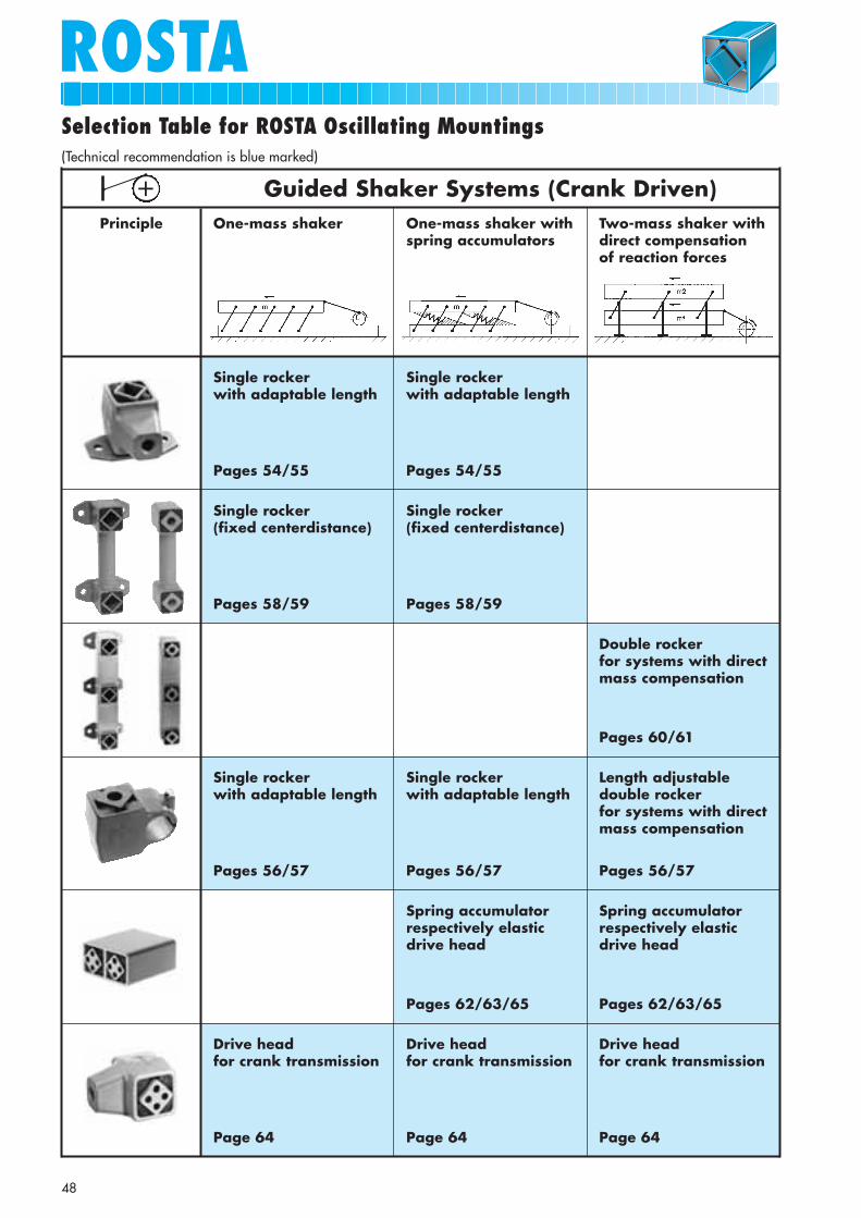
Guided Shaker Systems (Crank Driven)One-mass shaker
Single rocker with adaptable length
Pages 54/55
Single rocker with adaptable length
Pages 54/55
Single rocker (fixed centerdistance)
Pages 58/59
Single rocker (fixed centerdistance)
Pages 58/59
Single rocker with adaptable length
Pages 56/57
Drive head for crank transmission
Page 64
Single rocker with adaptable length
Pages 56/57
Spring accumulatorrespectively elasticdrive head
Pages 62/63/65
Drive head for crank transmission
Page 64
Length adjustabledouble rocker for systems with directmass compensation
Pages 56/57
Double rocker for systems with directmass compensation
Pages 60/61
Spring accumulatorrespectively elasticdrive head
Pages 62/63/65
Drive head for crank transmission
Page 64
One-mass shaker withspring accumulators
Two-mass shaker withdirect compensation of reaction forces
Principle
+(Technical recommendation is blue marked)
49
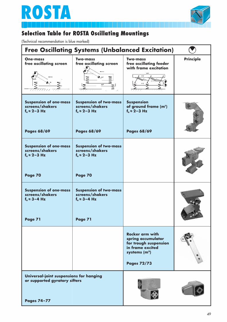
ROSTASelection Table for ROSTA Oscillating Mountings
Free Oscillating Systems (Unbalanced Excitation)One-mass free oscillating screen
Suspension of one-massscreens/shakers fe ~~ 2–3 Hz
Pages 68/69
Suspension of two-massscreens/shakers fe ~~ 2–3 Hz
Pages 68/69
Suspension of ground frame (m1) fe ~~ 2–3 Hz
Pages 68/69
Suspension of one-massscreens/shakersfe ~~ 2–3 Hz
Page 70
Suspension of two-massscreens/shakers fe ~~ 2–3 Hz
Page 70
Suspension of one-massscreens/shakersfe ~~ 3–4 Hz
Page 71
Suspension of two-massscreens/shakers fe ~~ 3–4 Hz
Page 71
Universal-joint suspensions for hanging or supported gyratory sifters
Pages 74–77
Rocker arm withspring accumulator for trough suspensionin frame excited systems (m2)
Pages 72/73
Two-mass free oscillating screen
Two-mass free oscillating feederwith frame excitation
Principle
(Technical recommendation is blue marked)
Osc
illa
ting
Mou
ntin
gs
ROSTATechnology
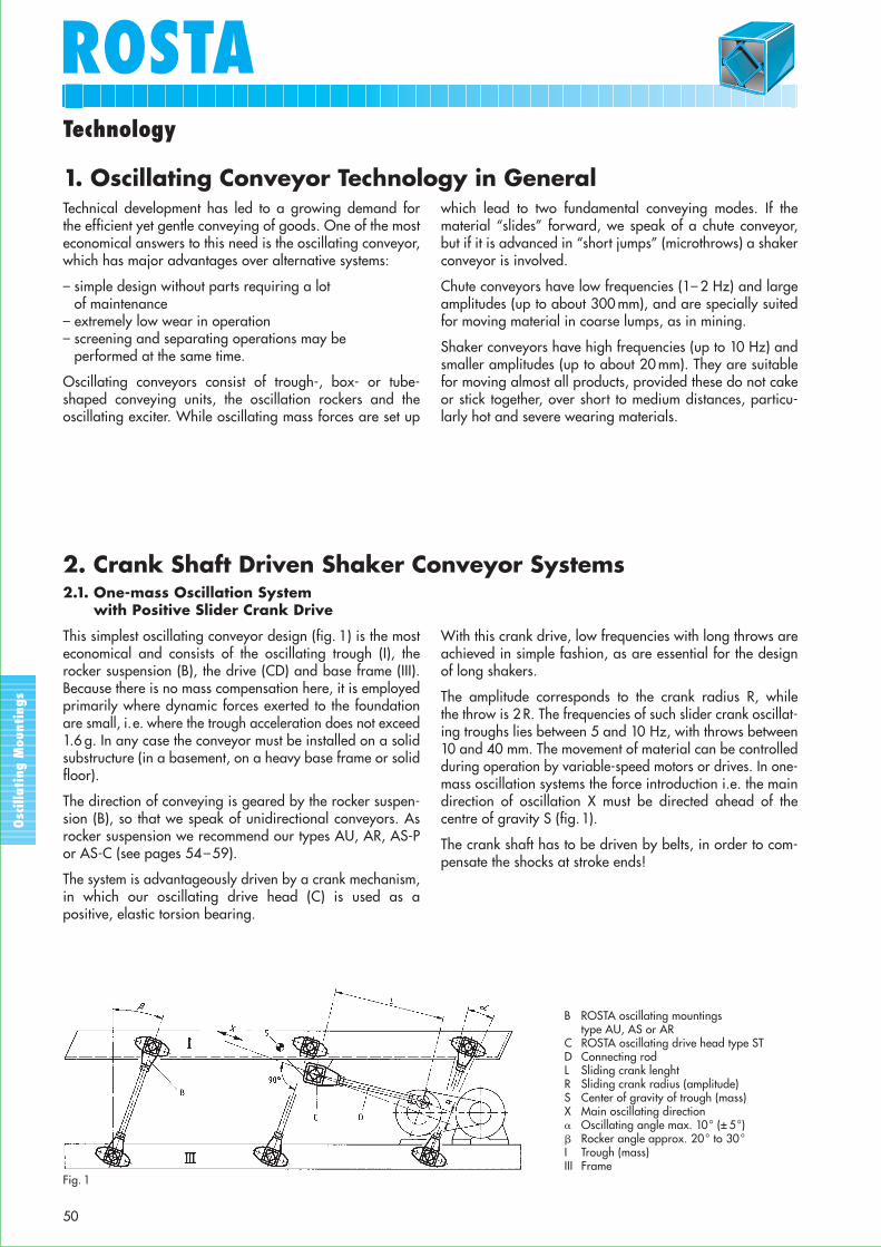
B ROSTA oscillating mountingstype AU, AS or AR
C ROSTA oscillating drive head type STD Connecting rodL Sliding crank lenghtR Sliding crank radius (amplitude)S Center of gravity of trough (mass)X Main oscillating direction� Oscillating angle max. 10° (± 5°)� Rocker angle approx. 20° to 30°I Trough (mass)III Frame
Fig. 1
50
Technical development has led to a growing demand forthe efficient yet gentle conveying of goods. One of the mosteconomical answers to this need is the oscillating conveyor,which has major advantages over alternative systems:
– simple design without parts requiring a lot of maintenance
– extremely low wear in operation– screening and separating operations may be
performed at the same time.
Oscillating conveyors consist of trough-, box- or tube-shaped conveying units, the oscillation rockers and theoscillating exciter. While oscillating mass forces are set up
which lead to two fundamental conveying modes. If thematerial “slides” forward, we speak of a chute conveyor,but if it is advanced in “short jumps” (microthrows) a shakerconveyor is involved.
Chute conveyors have low frequencies (1– 2 Hz) and largeamplitudes (up to about 300 mm), and are specially suitedfor moving material in coarse lumps, as in mining.
Shaker conveyors have high frequencies (up to 10 Hz) andsmaller amplitudes (up to about 20 mm). They are suitablefor moving almost all products, provided these do not cakeor stick together, over short to medium distances, particu-larly hot and severe wearing materials.
1. Oscillating Conveyor Technology in General
2.1. One-mass Oscillation System with Positive Slider Crank Drive
This simplest oscillating conveyor design (fig. 1) is the mosteconomical and consists of the oscillating trough (I), therocker suspension (B), the drive (CD) and base frame (III).Because there is no mass compensation here, it is employedprimarily where dynamic forces exerted to the foundationare small, i.e. where the trough acceleration does not exceed1.6 g. In any case the conveyor must be installed on a solidsubstructure (in a basement, on a heavy base frame or solidfloor).
The direction of conveying is geared by the rocker suspen-sion (B), so that we speak of unidirectional conveyors. Asrocker suspension we recommend our types AU, AR, AS-Por AS-C (see pages 54–59).
The system is advantageously driven by a crank mechanism,in which our oscillating drive head (C) is used as apositive, elastic torsion bearing.
With this crank drive, low frequencies with long throws areachieved in simple fashion, as are essential for the designof long shakers.
The amplitude corresponds to the crank radius R, while the throw is 2 R. The frequencies of such slider crank oscillat-ing troughs lies between 5 and 10 Hz, with throws between10 and 40 mm. The movement of material can be controlledduring operation by variable-speed motors or drives. In one-mass oscillation systems the force introduction i.e. the maindirection of oscillation X must be directed ahead of thecentre of gravity S (fig.1).
The crank shaft has to be driven by belts, in order to com-pensate the shocks at stroke ends!
2. Crank Shaft Driven Shaker Conveyor Systems

Osc
illa
ting
Mou
ntin
gs
ROSTATechnology
B ROSTA double suspensions type AD or AR
C ROSTA oscillating drive headtype ST
� Oscillation angle max. 10° (± 5°)
� Rocker angle approx. 20° to 30°
I Trough (mass)II CountermassIII Frame
Fig. 2
51
2.2. Two-mass Oscillation System with Positive Slider Crank Drive(Direct Compensation of Reaction Forces)
Higher conveying performance calls for higher frequenciesand amplitudes, which inevitably cause stronger dynamicforces to be exerted on the foundation. In the two-massoscillation system these forces are minimized due to thedirect mass compensation, allowing even long and heavyconveyors to be mounted on relatively light platform struc-tures or on upper floors.
Fig. 2 shows a shaker conveyor of this kind schematically.With trough I and the countermass (or trough) II having thesame mass, the latter performing a compensatory oscillat-ing movement in the opposite sense, the oscillation neutralpoint O lies in the middle of the double suspension B. If thestationary support III holds the suspension at point O, it
sustains only static forces, so that the machine frame III isvirtually no longer subject to dynamic loading. In this casewe speak of direct mass compensation. (If the counter-massis used as feeding trough, please note that transport direc-tion is identic with trough I.)
Our elements type AD-P, AD-C and AR are fitted as double-suspension to support the two troughs on the machineframe (see pages 56/57 and 60/61). The system is drivenby eccentric crank with the ROSTA drive head ST.
In contrast to the one-mass system, in the two-mass shakersystems the force introduction may be adapted where-soever to the trough (mass I) or to the counter weight (mass II).
2.3. Resonance Oscillating Conveyor with Positive Slider Crank Drive
To reduce the driving forces necessary, the shaker con-veyors as presented in 2.1 and 2.2 are operated also as aresonance system. Here the suspensions B (figs. 1 and 2) arekey components. Also the spring accumulators, consistingof two elements type DO-A, are supporting the dynamicstiffnes of the trough and are offering a harmonic oscilla-tion of the system, close by the resonance (see pages 62/63).Unlike conventional designs, our suspensions embodyingROSTA rubber suspension units are able to perform fourimportant functions simultaneously:
– supporting the static load– forming an oscillating system in which the dynamic
spring stiffness is determining the resonance drive-capacity
– dictating the direction of oscillation– insulating vibration and structure-borne noise
To obtain a system as close to resonance as possible,based on the dynamic spring value of the ROSTA elements,various data of the projected shaker conveyor trough areneeded. The number and size of the suspensions dependon the weight of the oscillating mass, on the conveyingcapacity desired, on the stroke and drive frequency. Thisdrive frequency must as a rule be 10 % lower than thenatural frequency of the installation. Typical calculations ofthis may be found on pages 55–65.
Osc
illa
ting
Mou
ntin
gs
Symbol Unit Term
a m/s2 Acceleration
A mm Center distance rockers
cd N/mm Dynamic spring value (rocker)
ct N/mm Total spring value (system)
fe Hz Natural frequency (elements)
ferr Hz Excitation frequency
F N Force
g 9.81 m/s2 Gravitational acceleration
Kmachine acc.
Oscillating machine factor
Symbol Unit Term
m kg Mass
nerr min–1 Revolutions per minute
R mm Crank radius
S – Center of gravity
sw = 2 · R mm Throw (peak to peak)
vth m/min cm/s Theoretical velocity (material)
z – Quantity (number)
W % Degree of isolation
α ° Oscillation angle
β ° Rocker angle (inclination)grav. acc.
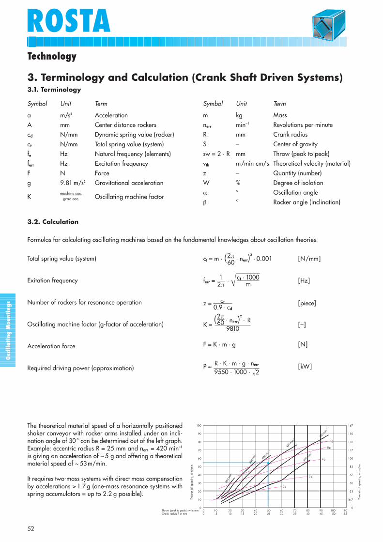
3.2. Calculation
Total spring value (system)
Exitation frequency
Number of rockers for resonance operation
Oscillating machine factor (g-factor of acceleration)
Acceleration force
Required driving power (approximation)
ct = m · (2π · nerr)2
· 0.001 [N/mm]
ferr = 1 ·�����c t · 1000 [Hz]
z = ct [piece]
K = (2π
· nerr)2
· R[–]
F = K · m · g [N]
P ≈ R · K · m · g · nerr [kW]
60
m
0.9 · cd
609810
9550 · 1000 · ��2
2π
Technology
ROSTA
52
The theoretical material speed of a horizontally positionedshaker conveyor with rocker arms installed under an incli-nation angle of 30° can be determined out of the left graph.Example: eccentric radius R = 25 mm and nerr = 420 min–1
is giving an acceleration of ~ 5 g and offering a theoreticalmaterial speed of ~ 53m/min.
It requires two-mass systems with direct mass compensationby accelerations > 1.7 g (one-mass resonance systems withspring accumulators = up to 2.2 g possible).
Formulas for calculating oscillating machines based on the fundamental knowledges about oscillation theories.
3. Terminology and Calculation (Crank Shaft Driven Systems)3.1. Terminology
300
min-1
360
min
420
min
480
min
540
min
600
min
-1
2g
3g
4g
5g
6g-1
-1
-1
-1
167
150
133
117
100
83
67
50
33
16.7
000
105
2010
3015
4020
5025
6030
7035
8040
9045
10050
11055
100
90
80
70
60
50
40
30
20
10
0
Theo
retic
al s
peed
vth in
m/m
in
Throw (peak to peak) sw in mmCrank raduis R in mm
Theo
retic
al s
peed
vth in
cm
/sec
Osc
illa
ting
Mou
ntin
gs
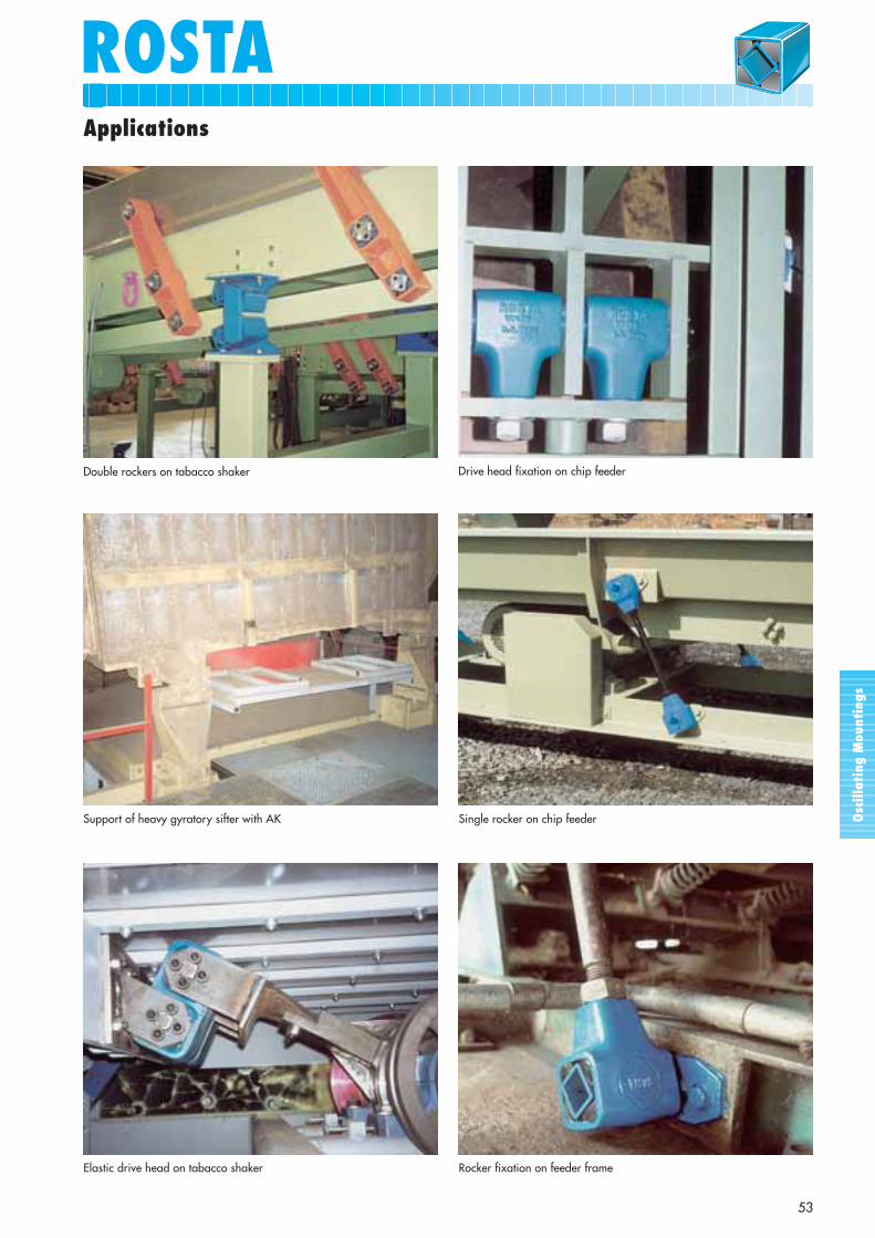
ROSTAApplications
53
Support of heavy gyratory sifter with AK Single rocker on chip feeder
Double rockers on tabacco shaker Drive head fixation on chip feeder
Elastic drive head on tabacco shaker Rocker fixation on feeder frame
Osc
illa
ting
Mou
ntin
gs
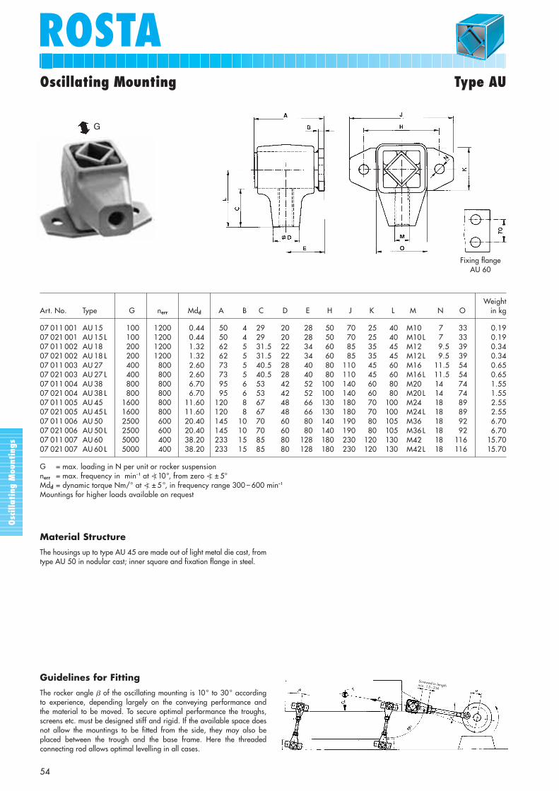
ROSTAOscillating Mounting Type AU
54
WeightArt. No. Type G nerr Mdd A B C D E H J K L M N O in kg
07 011 001 AU 15 100 1200 0.44 50 4 29.5 20 28 50 70 25 40 M10 7 33 0.1907 021 001 AU 15 L 100 1200 0.44 50 4 29.5 20 28 50 70 25 40 M10L 7 33 0.1907 011 002 AU 18 200 1200 1.32 62 5 31.5 22 34 60 85 35 45 M12 9.5 39 0.3407 021 002 AU 18 L 200 1200 1.32 62 5 31.5 22 34 60 85 35 45 M12L 9.5 39 0.3407 011 003 AU 27 400 800 2.60 73 5 40.5 28 40 80 110 45 60 M16 11.5 54 0.6507 021 003 AU 27 L 400 800 2.60 73 5 40.5 28 40 80 110 45 60 M16L 11.5 54 0.6507 011 004 AU 38 800 800 6.70 95 6 53.5 42 52 100 140 60 80 M20 14 74 1.5507 021 004 AU 38 L 800 800 6.70 95 6 53.5 42 52 100 140 60 80 M20L 14 74 1.5507 011 005 AU 45 1600 800 11.60 120 8 67.5 48 66 130 180 70 100 M24 18 89 2.5507 021 005 AU 45 L 1600 800 11.60 120 8 67.5 48 66 130 180 70 100 M24L 18 89 2.5507 011 006 AU 50 2500 600 20.40 145 10 70.5 60 80 140 190 80 105 M36 18 92 6.7007 021 006 AU 50 L 2500 600 20.40 145 10 70.5 60 80 140 190 80 105 M36L 18 92 6.7007 011 007 AU 60 5000 400 38.20 233 15 85.5 80 128 180 230 120 130 M42 18 116 15.7007 021 007 AU 60 L 5000 400 38.20 233 15 85.5 80 128 180 230 120 130 M42L 18 116 15.70
G = max. loading in N per unit or rocker suspensionnerr = max. frequency in min–1 at �) 10°, from zero �) ± 5°Mdd = dynamic torque Nm/° at �) ± 5°, in frequency range 300 – 600 min–1
Mountings for higher loads available on request
Guidelines for Fitting
The rocker angle � of the oscillating mounting is 10° to 30° according to experience, depending largely on the conveying performance and the material to be moved. To secure optimal performance the troughs,screens etc. must be designed stiff and rigid. If the available space doesnot allow the mountings to be fitted from the side, they may also be placed between the trough and the base frame. Here the threadedconnecting rod allows optimal levelling in all cases.
Fixing flangeAU 60
G
Screwed-in lengthmin. 1.5 – 2M
Material Structure
The housings up to type AU 45 are made out of light metal die cast, fromtype AU 50 in nodular cast; inner square and fixation flange in steel.
Osc
illa
ting
Mou
ntin
gs
ROSTAROSTA
55
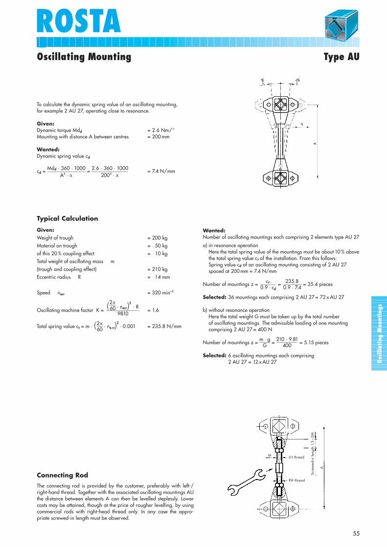
Oscillating Mounting Type AU
To calculate the dynamic spring value of an oscillating mounting, for example 2 AU 27, operating close to resonance.
Given:Dynamic torque Mdd = 2.6 Nm/°Mounting with distance A between centres = 200 mm
Wanted:Dynamic spring value cd
cd = Mdd · 360 · 1000 = 2.6 · 360 · 1000 = 7.4 N/mmA2 · π 2002 · π
Typical Calculation
Given:Weight of trough = 200 kgMaterial on trough = 50 kgof this 20 % coupling effect = 10 kgTotal weight of oscillating mass m(trough and coupling effect) = 210 kgEccentric radius R = 14 mm
Speed nerr = 320 min–1
Oscillating machine factor K = (2π
· nerr)2
· R= 1.6
Total spring value ct = m · (2π · ne rr)2· 0.001 = 235.8 N/mm
609810
60
Wanted:Number of oscillating mountings each comprising 2 elements type AU 27
a) in resonance operation Here the total spring value of the mountings must be about 10 % abovethe total spring value c t of the installation. From this follows:Spring value cd of an oscillating mounting consisting of 2 AU 27spaced at 200 mm = 7.4 N/mm
Number of mountings z = c t = 235.8 = 35.4 pieces
Selected: 36 mountings each comprising 2 AU 27 = 72 x AU 27
b) without resonance operationHere the total weight G must be taken up by the total number of oscillating mountings. The admissible loading of one mountingcomprising 2 AU 27 = 400 N
Number of mountings z = m · g
= 210 · 9.81
= 5.15 pieces
Selected: 6 oscillating mountings each comprising 2 AU 27 = 12 x AU 27
0.9 · 7.40.9 · cd
G 400
Connecting Rod
The connecting rod is provided by the customer, preferably with left-/right-hand thread. Together with the associated oscillating mountings AUthe distance between elements A can then be levelled steplessly. Lowercosts may be attained, though at the price of rougher levelling, by usingcommercial rods with right-head thread only. In any case the appro-priate screwed-in length must be observed.
Scre
wed
-in le
ngth
1.5
– 2M
A
M LH thread
RH thread

Osc
illa
ting
Mou
ntin
gs
ROSTA
56
N
M
O
BA
L
L1
H
CS
G Dimensions in mm WeightArt. No. Type K=2 K=3 K=4 nerr Mdd A B C H L L1 M N O S in kg
07 291 003 AR 27 300 240 200 590 2.6 39 ± 0.2 21.5 16 + 0.5+ 0.3 48 60 65 + 0
– 0.3 30 35 M8 27 0.4507 291 004 AR 38 600 500 400 510 6.7 52 ± 0.2 26.5 20 + 0.5
+ 0.2 64 80 90+ 0– 0.3 40 50 M8 38 0.95
G = max. load in G per rockerK = oscillating machine factornerr = max. frequency in min–1 with �) ± 5°Mdd = dynamic spring value in Nm/° at �) ± 5°, in frequency range 300 – 600 min–1
10–30°conveying direction
A
Single Drive Head
ROSTA oscillating mountings type AR in single rocker configuration: mounted on a round tube. It is best to adjustthe desired center-distance between the axes on a surface plate and to subsequently tighten the clamp in order tofrictionally connect the circular tube. The unit is fixed to the trough and the machine frame by means of frictional connectionto the inner square section of the element by means of a bolt.
Dynamic Spring Value
The dynamic spring value cd of an oscillation unit consisting of 2 elements, type AR, is calculated as following:
cd = = [N/mm]Mdd · 360 · 1000A2 · π
Oscillating Mounting Type AR
Material Structure
Housings in light metal die cast, inner square in light alloy profile.
Osc
illa
ting
Mou
ntin
gs
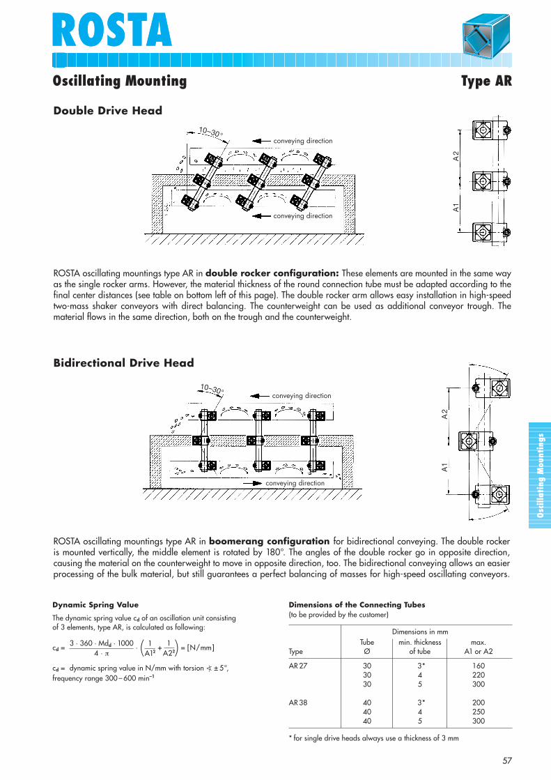
ROSTAROSTAOscillating Mounting Type AR
57
10–30°conveying direction
conveying direction
A1
A2
Dynamic Spring Value
The dynamic spring value cd of an oscillation unit consisting of 3 elements, type AR, is calculated as following:
cd = · + = [N/mm]
cd = dynamic spring value in N/mm with torsion �) ± 5°, frequency range 300 – 600 min–1
Dimensions in mmTube min. thickness max.
Type Ø of tube A1 or A2
AR 27 30 3* 16030 4 22030 5 300
AR 38 40 3* 20040 4 25040 5 300
* for single drive heads always use a thickness of 3 mm
( )
Dimensions of the Connecting Tubes(to be provided by the customer)
A1
A2
10–30°
conveying direction
conveying direction
Double Drive Head
ROSTA oscillating mountings type AR in double rocker configuration: These elements are mounted in the same wayas the single rocker arms. However, the material thickness of the round connection tube must be adapted according to thefinal center distances (see table on bottom left of this page). The double rocker arm allows easy installation in high-speedtwo-mass shaker conveyors with direct balancing. The counterweight can be used as additional conveyor trough. Thematerial flows in the same direction, both on the trough and the counterweight.
Bidirectional Drive Head
ROSTA oscillating mountings type AR in boomerang configuration for bidirectional conveying. The double rockeris mounted vertically, the middle element is rotated by 180°. The angles of the double rocker go in opposite direction,causing the material on the counterweight to move in opposite direction, too. The bidirectional conveying allows an easierprocessing of the bulk material, but still guarantees a perfect balancing of masses for high-speed oscillating conveyors.
3 · 360 · Mdd · 10004 · π
1A12
1A22
Osc
illa
ting
Mou
ntin
gs
ROSTA
58
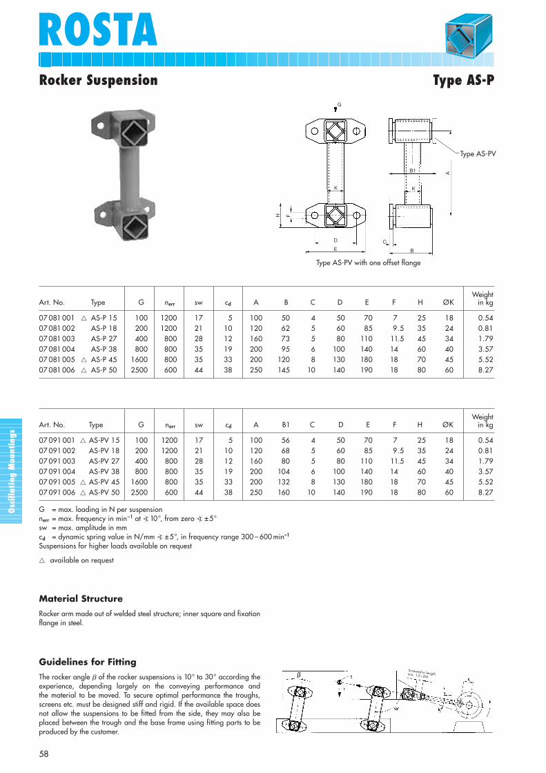
Rocker Suspension Type AS-P
WeightArt. No. Type G nerr sw cd A B C D E F H ØK in kg
07 081 001 � AS-P 15 100 1200 17 5 100 50 4 50 70 7 25 18 0.5407 081 002 AS-P 18 200 1200 21 10 120 62 5 60 85 9.5 35 24 0.8107 081 003 AS-P 27 400 800 28 12 160 73 5 80 110 11.5 45 34 1.7907 081 004 AS-P 38 800 800 35 19 200 95 6 100 140 14 60 40 3.5707 081 005 � AS-P 45 1600 800 35 33 200 120 8 130 180 18 70 45 5.5207 081 006 � AS-P 50 2500 600 44 38 250 145 10 140 190 18 80 60 8.27
WeightArt. No. Type G nerr sw cd A B1 C D E F H ØK in kg
07 091 001 � AS-PV 15 100 1200 17 5 100 56 4 50 70 7 25 18 0.5407 091 002 AS-PV 18 200 1200 21 10 120 68 5 60 85 9.5 35 24 0.8107 091 003 AS-PV 27 400 800 28 12 160 80 5 80 110 11.5 45 34 1.7907 091 004 AS-PV 38 800 800 35 19 200 104 6 100 140 14 60 40 3.5707 091 005 � AS-PV 45 1600 800 35 33 200 132 8 130 180 18 70 45 5.5207 091 006 � AS-PV 50 2500 600 44 38 250 160 10 140 190 18 80 60 8.27
G = max. loading in N per suspensionnerr = max. frequency in min–1 at �) 10°, from zero �) ±5°sw = max. amplitude in mmcd = dynamic spring value in N/mm �) ±5°, in frequency range 300 – 600 min–1
Suspensions for higher loads available on request
� available on request
G
K
H F
D
E
B1 A
K
C
B
Type AS-PV
Type AS-PV with one offset flange
Guidelines for Fitting
The rocker angle � of the rocker suspensions is 10° to 30° according theexperience, depending largely on the conveying performance and the material to be moved. To secure optimal performance the troughs,screens etc. must be designed stiff and rigid. If the available space doesnot allow the suspensions to be fitted from the side, they may also be placed between the trough and the base frame using fitting parts to beproduced by the customer.
Screwed-in lengthmin. 1.5 – 2M
Material Structure
Rocker arm made out of welded steel structure; inner square and fixationflange in steel.

Osc
illa
ting
Mou
ntin
gs
ROSTAROSTA
59
Rocker Suspension Type AS-C
WeightArt. No. Type G nerr sw cd A B C D E ØF in kg
07 071 001 � AS-C 15 100 1200 17 5 100 40 2.5 45 10 + 0.4+ 0.2 18 0.38
07 071 002 AS-C 18 200 1200 21 10 120 50 2.5 55 13 + 0.4– 0.2 24 0.56
07 071 003 AS-C 27 400 800 28 12 160 60 2.5 65 16 + 0.5+ 0.3 34 1.31
07 071 004 AS-C 38 800 800 35 19 200 80 5 90 20 + 0.5+ 0.2 40 2.60
07 071 005 � AS-C 45 1600 800 35 33 200 100 5 110 24 + 0.5+ 0.2 45 3.94
07 071 006 � AS-C 50 2500 600 44 38 250 120 5 130 30 + 0.5+ 0.2 60 6.05
G = max. loading in N per suspensionnerr = max. frequency in min–1 at �) 10°, from zero �) ±5°sw = max. amplitude in mmcd = dynamic spring value in N/mm at �) ±5°, in frequency range 300 – 600 min–1
Suspensions for higher loads available on request
� available on request
Typical Calculation
Given:Weight of trough = 200 kgMaterial on trough = 50 kgof this 20 % coupling effect = 10 kgTotal weight of oscillating mass m(trough and coupling effect) = 210 kg
Eccentric radius R = 14 mm
Speed nerr = 320 min–1
Oscillating machine factor K =(2π
· nerr)2
· R= 1.6
Total spring value ct = m · (2π· nerr)
2· 0.001 = 235.8 N/mm
609810
60
Wanted:Number of double rocker suspensions of size 27 for example
a) in resonance operationHere the total spring value of the suspensions must be about 10 %above the total spring value ct of the installation. From this follows:Spring value cd of the rocker suspension AS 27 = 12 N/mm
Number of suspensions z = ct = 235.8 = 21.8 pieces
Selected: 22 of AS-P 27 or AS-C 27
b) without resonance operationHere the total weight G must be taken up by the total number of rocker suspensions. The admissible loading of one AS 27suspension is 400 N
Number of suspensions z = m · g = 210 · 9.81 = 5.15 pieces
Selected: 6 of AS-P 27 or AS-C 27
0.9 · 120.9 · cd
G 400
E
K
A
G
K
B
D
C
Material Structure
Rocker arm made out of welded steel structure; inner squarein light alloy profile.
Osc
illa
ting
Mou
ntin
gs
ROSTA
60
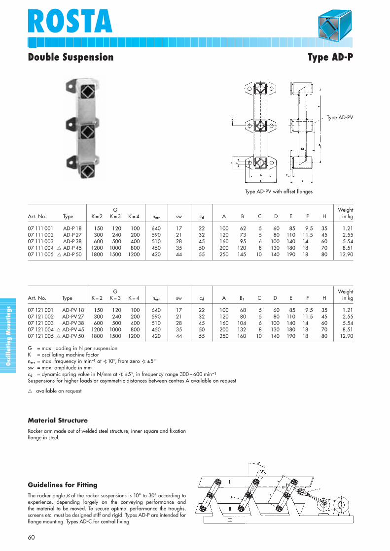
Double Suspension Type AD-P
G WeightArt. No. Type K = 2 K = 3 K = 4 nerr sw cd A B C D E F H in kg
07 111 001 AD-P 18 150 120 100 640 17 22 100 62 5 60 85 9.5 35 1.2107 111 002 AD-P 27 300 240 200 590 21 32 120 73 5 80 110 11.5 45 2.5507 111 003 AD-P 38 600 500 400 510 28 45 160 95 6 100 140 14,5 60 5.5407 111 004 � AD-P 45 1200 1000 800 450 35 50 200 120 8 130 180 18,5 70 8.5107 111 005 � AD-P 50 1800 1500 1200 420 44 55 250 145 10 140 190 18,5 80 12.90
G WeightArt. No. Type K = 2 K = 3 K = 4 nerr sw cd A B1 C D E F H in kg
07 121 001 AD-PV 18 150 120 100 640 17 22 100 68 5 60 85 9.5 35 1.2107 121 002 AD-PV 27 300 240 200 590 21 32 120 80 5 80 110 11.5 45 2.5507 121 003 AD-PV 38 600 500 400 510 28 45 160 104 6 100 140 14,5 60 5.5407 121 004 � AD-PV 45 1200 1000 800 450 35 50 200 132 8 130 180 18,5 70 8.5107 121 005 � AD-PV 50 1800 1500 1200 420 44 55 250 160 10 140 190 18,5 80 12.90
G = max. loading in N per suspensionK = oscillating machine factornerr = max. frequency in min–1 at �) 10°, from zero �) ±5°sw = max. amplitude in mmcd = dynamic spring value in N/mm at �) ±5°, in frequency range 300 – 600 min–1
Suspensions for higher loads or asymmetric distances between centres A available on request
� available on request
Guidelines for Fitting
The rocker angle � of the rocker suspensions is 10° to 30° according toexperience, depending largely on the conveying performance and the material to be moved. To secure optimal performance the troughs,screens etc. must be designed stiff and rigid. Types AD-P are intended forflange mounting. Types AD-C for central fixing.
Type AD-PV with offset flanges
Type AD-PV
Material Structure
Rocker arm made out of welded steel structure; inner square and fixationflange in steel.
Osc
illa
ting
Mou
ntin
gs
ROSTAROSTA
61
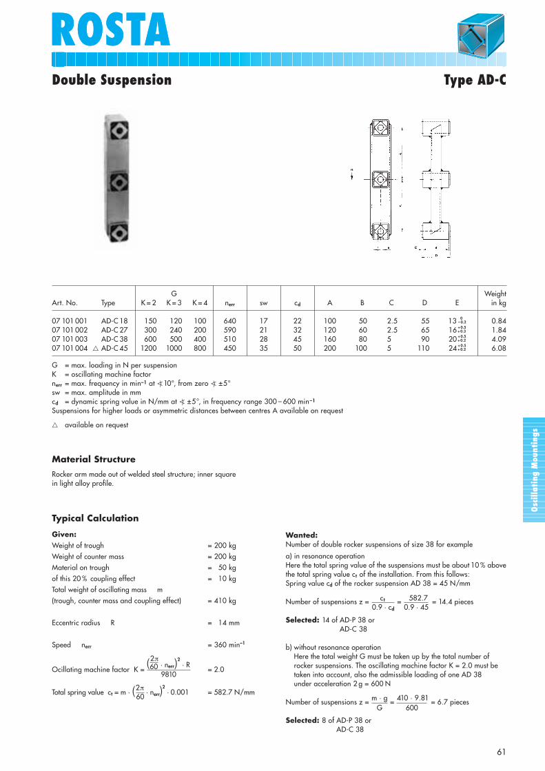
Double Suspension Type AD-C
G WeightArt. No. Type K = 2 K = 3 K = 4 nerr sw cd A B C D E in kg
07 101 001 AD-C 18 150 120 100 640 17 22 100 50 2.5 55 13 + 0.0– 0.2 0.84
07 101 002 AD-C 27 300 240 200 590 21 32 120 60 2.5 65 16 + 0.5+ 0.3 1.84
07 101 003 AD-C 38 600 500 400 510 28 45 160 80 5.5 90 20 + 0.5+ 0.2 4.09
07 101 004 � AD-C 45 1200 1000 800 450 35 50 200 100 5.5 110 24 + 0.5+ 0.2 6.08
G = max. loading in N per suspensionK = oscillating machine factornerr = max. frequency in min–1 at �) 10°, from zero �) ±5°sw = max. amplitude in mmcd = dynamic spring value in N/mm at �) ±5°, in frequency range 300 – 600 min–1
Suspensions for higher loads or asymmetric distances between centres A available on request
� available on request
Typical Calculation
Given:Weight of trough = 200 kgWeight of counter mass = 200 kgMaterial on trough = 50 kgof this 20 % coupling effect = 10 kgTotal weight of oscillating mass m(trough, counter mass and coupling effect) = 410 kg
Eccentric radius R = 14 mm
Speed nerr = 360 min–1
Ocillating machine factor K =(2π
· nerr)2· R
= 2.0
Total spring value ct = m · (2π· nerr)
2· 0.001 = 582.7 N/mm
609810
60
Wanted:Number of double rocker suspensions of size 38 for example
a) in resonance operationHere the total spring value of the suspensions must be about 10 % abovethe total spring value ct of the installation. From this follows:Spring value cd of the rocker suspension AD 38 = 45 N/mm
Number of suspensions z = c t = 582.7 = 14.4 pieces
Selected: 14 of AD-P 38 or AD-C 38
b) without resonance operationHere the total weight G must be taken up by the total number ofrocker suspensions. The oscillating machine factor K = 2.0 must betaken into account, also the admissible loading of one AD 38 under acceleration 2 g = 600 N
Number of suspensions z = m · g = 410 · 9.81 = 6.7 pieces
Selected: 8 of AD-P 38 orAD-C 38
0.9 · 450.9 · cd
G 600
Material Structure
Rocker arm made out of welded steel structure; inner squarein light alloy profile.
Osc
illa
ting
Mou
ntin
gs
ROSTA
62
WeightArt. No. Type cd L L1 0
–0.3 A B D E F G H I S in kg
01 041 013 DO-A 45 x 80 220 80 90 12 + 0.50 35 ± 0.5 85 73 149.4 – 0.4
+ 1.6 45 1.8501 041 014 DO-A 45 x 100 260 100 110 12 + 0.5
0 35 ± 0.5 85 73 149.4 – 0.4+ 1.6 45 2.26
01 041 016 DO-A 50 x 120 400 120 130 M12 40 ± 0.5 89 78 167 30 60 12.25 50 5.5001 041 019 DO-A 50 x 160 500 160 170 M12 40 ± 0.5 88 78 166 30 60 12.25 50 7.4001 041 017 DO-A 50 x 200 600 200 210 M12 40 ± 0.5 89 78 167 40 70 12.25 50 8.50
* DO-A 45 with convex housing shape
A spring accumulator consists of two ROSTA rubber suspension unitstype DO-A and a customer supplied connection link V. The dynamicspring value of this configuration corresponds to only 50 % of a singleDO-A element, due to the effected double serie-connection, whichis reducing the dynamic stiffness to half.
Element Perm. Type cd osc. angle R sw nerr
2 x DO-A45 x 80 110 ±5° 12.5 25.0 520±4° 10.0 20.0 780±3° 7.5 15.0 1280
2 x DO-A45 x 100 130 ±5° 12.5 25.0 480±4° 10.0 20.0 720±3° 7.5 15.0 1200
2 x DO-A50 x 120 200 ±5° 13.6 27.2 420±4° 10.9 21.8 600±3° 8.2 16.4 960
2 x DO-A50 x 160 250 ±5° 13.6 27.2 400±4° 10.9 21.8 570±3° 8.2 16.4 910
2 x DO-A50 x 200 300 ±5° 13.6 27.2 380±4° 10.9 21.8 540±3° 8.2 16.4 860
cd = dynamic spring value in N/mmR = permissible radius in mmsw = max. amplitude (peak to peak) in mmnerr = max. frequency in min–1
HG
A I
LL1
EF
D D
R 180DO-A 45*B
A40
S
BØ 20 (Type DO-A 50)+ 0.5
+ 0
Only type DO-A 50
trough
parallel
frame
�Rubber Suspension Unit Type DO-A(as Spring Accumulator)
Material Structure
Housing of size 45 is made out of light alloy profile, housing of size 50in nodular cast; inner squares in light alloy profile with 4 bores for thefixation of connection brackets shaker: frame.
Osc
illa
ting
Mou
ntin
gs
ROSTAROSTA
63
Rubber Suspension Unit Type DO-A
I
II
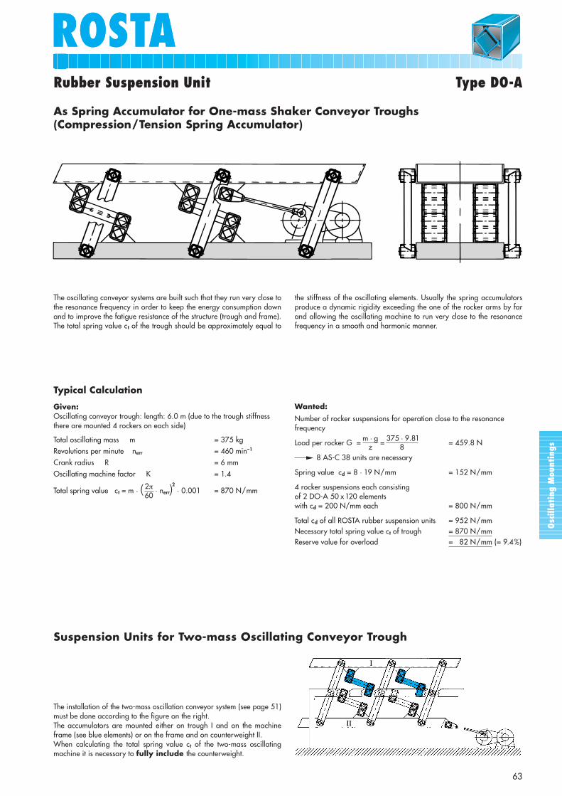
The oscillating conveyor systems are built such that they run very close tothe resonance frequency in order to keep the energy consumption downand to improve the fatigue resistance of the structure (trough and frame).The total spring value ct of the trough should be approximately equal to
the stiffness of the oscillating elements. Usually the spring accumulatorsproduce a dynamic rigidity exceeding the one of the rocker arms by farand allowing the oscillating machine to run very close to the resonancefrequency in a smooth and harmonic manner.
The installation of the two-mass oscillation conveyor system (see page 51)must be done according to the figure on the right. The accumulators are mounted either on trough I and on the machineframe (see blue elements) or on the frame and on counterweight II.When calculating the total spring value ct of the two-mass oscillatingmachine it is necessary to fully include the counterweight.
Suspension Units for Two-mass Oscillating Conveyor Trough
As Spring Accumulator for One-mass Shaker Conveyor Troughs(Compression/Tension Spring Accumulator)
Wanted:
Number of rocker suspensions for operation close to the resonance frequency
Load per rocker G = m · g = 375 · 9.81 = 459.8 N
8 AS-C 38 units are necessary
Spring value cd = 8 · 19 N/mm = 152 N/mm
4 rocker suspensions each consistingof 2 DO-A 50 x 120 elementswith cd = 200 N/mm each = 800 N/mm
Total cd of all ROSTA rubber suspension units = 952 N/mmNecessary total spring value ct of trough = 870 N/mmReserve value for overload = 82 N/mm (= 9.4%)
Typical Calculation
Given:Oscillating conveyor trough: length: 6.0 m (due to the trough stiffnessthere are mounted 4 rockers on each side)
Total oscillating mass m = 375 kgRevolutions per minute nerr = 460 min–1
Crank radius R = 6 mmOscillating machine factor K = 1.4
Total spring value ct = m · ( 2π · nerr)2
· 0.001 = 870 N/mm60
z 8
Osc
illa
ting
Mou
ntin
gs
ROSTA
64
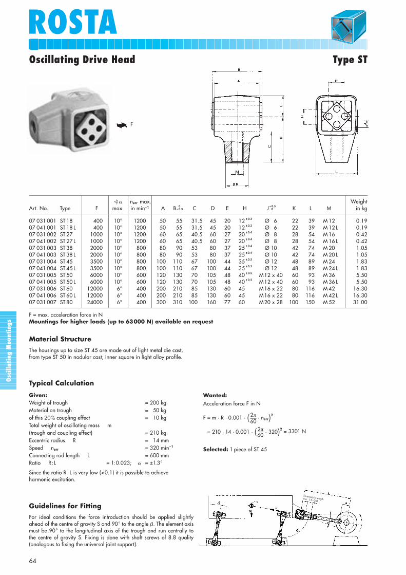
Oscillating Drive Head Type ST
�) � nerr max. WeightArt. No. Type F max. in min–1 A B 0
– 0.3 C D E H J + 0.50 K L M in kg
07 031 001 ST 18 400 10° 1200 50 55 31.5 45 20 12 ± 0.3 Ø 6 22 39 M 12 0.1907 041 001 ST 18 L 400 10° 1200 50 55 31.5 45 20 12 ± 0.3 Ø 6 22 39 M 12 L 0.1907 031 002 ST 27 1000 10° 1200 60 65 40.5 60 27 20 ± 0.4 Ø 8 28 54 M 16 0.4207 041 002 ST 27 L 1000 10° 1200 60 65 40.5 60 27 20 ± 0.4 Ø 8 28 54 M 16 L 0.4207 031 003 ST 38 2000 10° 800 80 90 53 80 37 25 ± 0.4 Ø 10 42 74 M 20 1.0507 041 003 ST 38 L 2000 10° 800 80 90 53 80 37 25 ± 0.4 Ø 10 42 74 M 20 L 1.0507 031 004 ST 45 3500 10° 800 100 110 67 100 44 35 ± 0.5 Ø 12 48 89 M 24 1.8307 041 004 ST 45 L 3500 10° 800 100 110 67 100 44 35 ± 0.5 Ø 12 48 89 M 24 L 1.8307 031 005 ST 50 6000 10° 600 120 130 70 105 48 40 ± 0.5 M12 x 40 60 93 M 36 5.5007 041 005 ST 50 L 6000 10° 600 120 130 70 105 48 40 ± 0.5 M12 x 40 60 93 M 36 L 5.5007 031 006 ST 60 12000 6° 400 200 210 85 130 60 45 ± 0.5 M16 x 22 80 116 M 42 16.3007 041 006 ST 60 L 12000 6° 400 200 210 85 130 60 45 ± 0.5 M16 x 22 80 116 M 42 L 16.3007 031 007 ST 80 24000 6° 400 300 310 100 160 77 60 ± 0.5 M20 x 28 100 150 M 52 31.00
F = max. acceleration force in NMountings for higher loads (up to 63000 N) available on request
Wanted:Acceleration force F in N
F = m · R · 0.001 · (2π · nerr)2
F = 210 · 14 · 0.001 · (2π · 320)2 = 3301 N
Selected: 1 piece of ST 45
60
Typical Calculation
Given:Weight of trough = 200 kgMaterial on trough = 50 kgof this 20% coupling effect = 10 kgTotal weight of oscillating mass m(trough and coupling effect) = 210 kgEccentric radius R = 14 mmSpeed nerr = 320 min–1
Connecting rod length L = 600 mmRatio R:L = 1:0.023; � = ±1.3°
Since the ratio R : L is very low (<0.1) it is possible to achieve harmonic excitation.
60
Guidelines for Fitting
For ideal conditions the force introduction should be applied slightlyahead of the centre of gravity S and 90° to the angle �. The element axismust be 90° to the longitudinal axis of the trough and run centrally to the centre of gravity S. Fixing is done with shaft screws of 8.8 quality(analogous to fixing the universal joint support).
Screwed-in lengthmin. 1.5 – 2M
F
Material Structure
The housings up to size ST 45 are made out of light metal die cast, from type ST 50 in nodular cast; inner square in light alloy profile.
Osc
illa
ting
Mou
ntin
gs
ROSTAROSTA
65
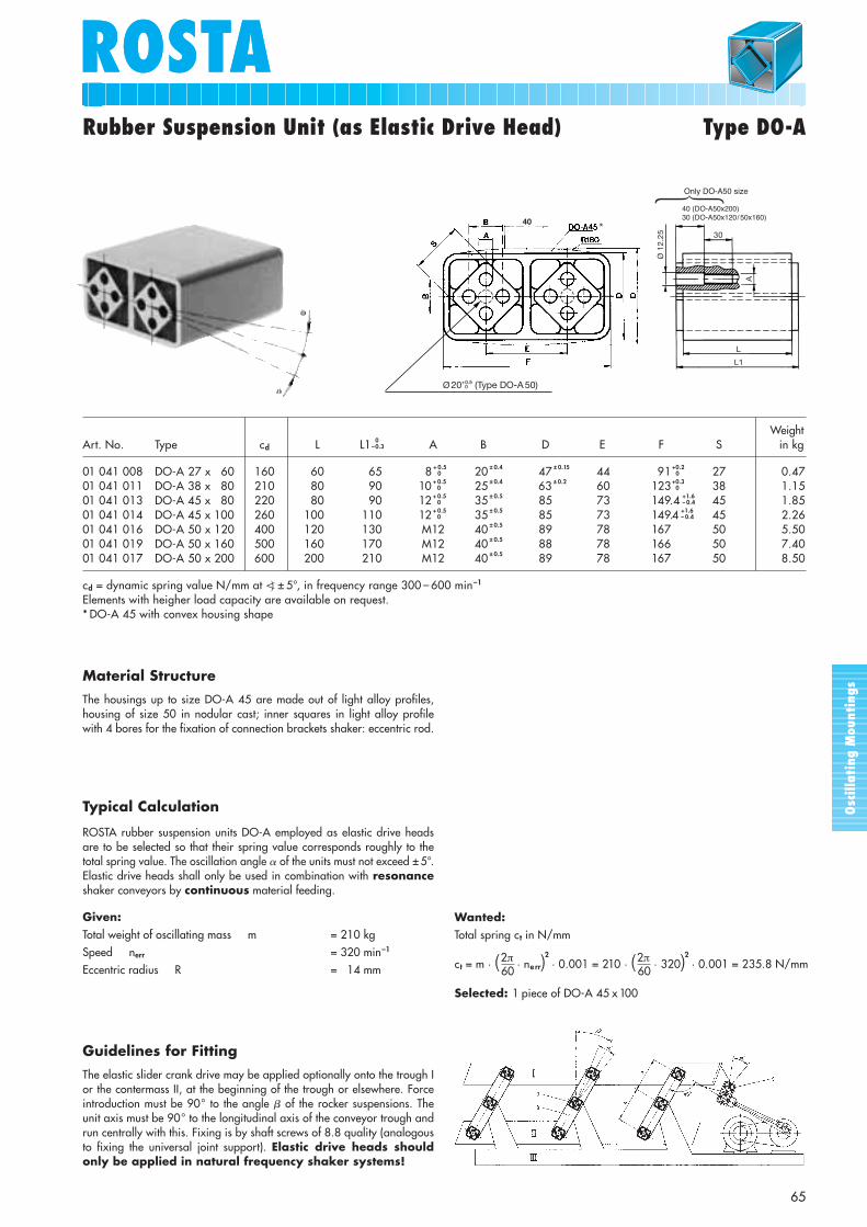
Rubber Suspension Unit (as Elastic Drive Head) Type DO-A
WeightArt. No. Type cd L L1 0
–0.3 A B D E F S in kg
01 041 008 DO-A 27 x 60 160 60 65 8 + 0.50 20 ± 0.4 47 ± 0.15 44 91 0
+0.2 27 0.4701 041 011 DO-A 38 x 80 210 80 90 10 + 0.5
0 25 ± 0.4 63 ± 0.2 60 123 0+0.3 38 1.15
01 041 013 DO-A 45 x 80 220 80 90 12 + 0.50 35 ± 0.5 85 73 149.4 – 0.4
+1.6 45 1.8501 041 014 DO-A 45 x 100 260 100 110 12 + 0.5
0 35 ± 0.5 85 73 149.4 – 0.4+1.6 45 2.26
01 041 016 DO-A 50 x 120 400 120 130 M12 40 ± 0.5 89 78 167 50 5.5001 041 019 DO-A 50 x 160 500 160 170 M12 40 ± 0.5 88 78 166 50 7.4001 041 017 DO-A 50 x 200 600 200 210 M12 40 ± 0.5 89 78 167 50 8.50
cd = dynamic spring value N/mm at �) ± 5°, in frequency range 300 – 600 min–1
Elements with heigher load capacity are available on request.* DO-A 45 with convex housing shape
Wanted:Total spring ct in N/mm
ct = m · (2π · ne rr)2
· 0.001 = 210 · (2π · 320)2 · 0.001 = 235.8 N/mm
Selected: 1 piece of DO-A 45 x 100
60
Typical Calculation
ROSTA rubber suspension units DO-A employed as elastic drive headsare to be selected so that their spring value corresponds roughly to thetotal spring value. The oscillation angle � of the units must not exceed ± 5°.Elastic drive heads shall only be used in combination with resonanceshaker conveyors by continuous material feeding.
Given:Total weight of oscillating mass m = 210 kgSpeed nerr = 320 min–1
Eccentric radius R = 14 mm 60
Guidelines for Fitting
The elastic slider crank drive may be applied optionally onto the trough Ior the contermass II, at the beginning of the trough or elsewhere. Forceintroduction must be 90° to the angle � of the rocker suspensions. Theunit axis must be 90° to the longitudinal axis of the conveyor trough andrun centrally with this. Fixing is by shaft screws of 8.8 quality (analogousto fixing the universal joint support). Elastic drive heads shouldonly be applied in natural frequency shaker systems!
Ø 20 (Type DO-A 50)+ 0.5+ 0
40
A
30
L
L1
40 (DO-A 50x200)30 (DO-A 50x120)
Ø 1
2.25
�*
Only DO-A50 size
Material Structure
The housings up to size DO-A 45 are made out of light alloy profiles,housing of size 50 in nodular cast; inner squares in light alloy profilewith 4 bores for the fixation of connection brackets shaker: eccentric rod.
40 (DO-A50x200)30 (DO-A50x120/50x160)

Osc
illa
ting
Mou
ntin
gs
ROSTATechnology
66
B ROSTA oscillating mountingstype AB
S Centre of gravity of screenS1 Centre of gravity
of unbalanced motorI ScreenIII Frame
B ROSTA oscillating mountingstype AB
E ROSTA rubber suspension unitstype DK-A with clamp BK
S Centre of gravity of screenI ScreenIII Frame
feeding direction
Freely oscillating one-mass systems (figs. 4 to 6) are sup-ported with ROSTA oscillating mountings type AB and AB-D.In this case the angle at which the excitation force is appliedon the through determines the direction of oscillation.Thanks to the low frequency support, free oscillators imposeonly very small dynamic loads on the foundation. Howeverfor reasons of structure stiffnes (max. 7 m), only certainconveyor lengths can be executed, otherwise oscillationnodes occur which obstruct conveying.Free oscillating conveyors are driven by non-positive inertiadrives exploiting the action of rotating unbalanced masses
(unbalanced motors, exciters, eccentric double shafts).Suitable mounting of the drive systems ensures that therevolving unbalance is utilized only by the components in the actual direction of conveying. For example, twounbalanced masses counterrotating synchronously set upthe necessary excitation force in that the flow componentsin the direction of the line joining the two centres of rota-tion cancel each other out, while those at right angles addup to give the harmonic excitation force. To avoid theunbalanced masses assuming excessive magnitude, theexcitation frequency =~12 to 50 Hz.
4. Free Oscillation Systems
4.1. Drive with one Unbalanced Motor
This alternative (fig. 4) is used mainly on circular oscillators,which are used mostly for inclined screen constructions. If an unbalanced motor is flanged onto a screening unit, the
system performs slightly elliptical motions whose shapedepends on the distance between the two centres of gravity S(screen) and S1 (unbalanced motor), and on the screen design.
4.2. Drive with one Unbalanced Motor and Pendulum Mount
Linear oscillators with unbalanced motor on a pendulummount (fig. 5) are employed for screens and short, lightconveyors.If an unbalanced motor is flanged onto a machine throughon a pendulum mount E (e.g. DK-A with bracket BK, pages23 and 24) so that the centres of the motor and oscillating
bearing and the centre of gravity of the screen lie in a straightline, then approximately linear oscillations will be gener-ated. Through the pendulum mount the centrifugal forcesare transmitted almost entirely to the screen or trough,where as the transverse forces remain ineffective. The pen-dulum mount drive may be used only with smaller machines.
feeding direction
Osc
illa
ting
Mou
ntin
gs
ROSTAROSTA
67
Technology
4.3. Drive with two Unbalanced Motors
If two unbalanced motors are used with a linear shaker orscreen (fig. 6), it must be borne in mind that they counter-
Formulas for the principal variables of a free oscillator:
Guiding values: conveying speed for linear freeoscillating screens
From the intersection of the coordinates amplitude = 4 mmand motor speed n = 1460 rpm, with acceleration around 5 g the conveying speed emerges as 25 cm/sec.
Oscillating amplitude
sw =working torque in kgcm
· 10 = mm
Oscillating machine factor
Insulation efficiency
total weight in kg
K = (2π
· nerr)2
· sw= [–]
W = 100 – 100 = %
609810 · 2
( ferr)2
–1fe
B ROSTA oscillating mountingstype AB
S Centre of gravity of trough/screen
I Trough/screenIII Frame
Beschleunigung
Throw (peak to peak) sw in mmCrank radius R in mm
Theo
retic
al c
onve
ying
spe
ed v
th in
m/m
in
42
36
30
24
18
12
6
70
60
50
40
30
20
10
0.4 1 2 3 4 5 6 7 8 9 10 200.2 0.5 1 1.5 2 2.5 3 3.5 4 4.5 5 10
Theo
retic
al c
onve
ying
spe
ed v
th in
cm
/sec
rotate and are joined absolutely rigid, so that they synchron-ize at once when switched on, setting-up linear oscillations.
feeding direction
4.4. Calculation for a Linear Oscillator with two Unbalanced Motors
The proper size of the oscillation mountings type AB or AB-Dis determined as follows:Oscillating weight (conveyor with 2 motors + proportion ofmaterial being moved) divided by number of supportpoints (the individual points must be loaded approximatelyequally).At least 4 supports, if not more, are needed for the suspen-sion of a linear oscillator. (Very often, due to the mountingposition of the unbalanced motors, lies the position of the
center of gravity close by the discharge-end. The loadarrangement “discharge-end : feed-end” is therefore veryoften 60 % : 40 % and requires at least 6 or more mounts.)The excitation frequency may be neglected, because accord-ing to experience the amplitudes do not exceed 15 mm, sothat the oscillation angles are relatively small. The naturalfrequency of the AB must be at least 3 times lower than itsexcitation frequency.
ROSTAROSTA
68
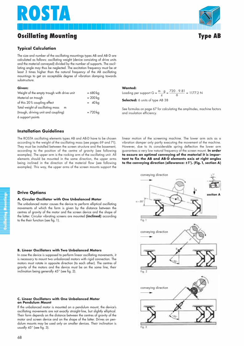
Oscillating Mounting Type AB
Given:Weight of the empty trough with drive unit = 680 kgMaterial on trough = 200 kgof this 20 % coupling effect = 40 kgTotal weight of oscillating mass m(trough, driving unit and coupling) = 720 kg6 support points
Wanted:Loading per support G = m · g = 720 · 9.81 = 1177.2 N
Selected: 6 units of type AB 38
See formulas on page 67 for calculating the amplitudes, machine factorsand insulation efficiency.
6z
Typical Calculation
The size and number of the oscillating mountings types AB and AB-D arecalculated as follows: oscillating weight (device consisting of drive unitsand the material conveyed) divided by the number of supports. The oscil-lating angle may thus be neglected. The excitation frequency must be atleast 3 times higher than the natural frequency of the AB oscillatingmountings to get an acceptable degree of vibration damping towardssubstructure.
Installation Guidelines
The ROSTA oscillating elements types AB and AB-D have to be chosenaccording to the weight of the oscillating mass (see pages 69 and 71).They must be installed between the screen structure and the basement,according to the position of the centre of gravity (see followingexamples). The upper arm is the rocking arm of the oscillating unit. Allelements should be mounted in the same direction, the upper armsbeing inclined in the direction of the material flow (see followingexamples). This way, the upper arms of the screen mounts support the
linear motion of the screening machine. The lower arm acts as avibration damper only partly executing the movement of the machine.However, due to its considerable spring deflection the lower armguarantees a very low natural frequency of the screen mount. In orderto assure an optimal conveying of the material it is impor-tant to fix the AB and AB-D elements axis at right anglesto the conveying direction (allowance: ±1°). (Fig. 1, section A)
Drive Options
A. Circular Oscillator with One Unbalanced MotorThe unbalanced motor causes the device to perform elliptical oscillatingmovements of which the form is given by the distance between thecentres of gravity of the motor and the screen device and the shape of the latter. Circular vibrating screens are mounted (inclined) accordingto the their function (see fig. 1).
B. Linear Oscillators with Two Unbalanced MotorsIn case the device is supposed to perform linear oscillating movements, itis necessary to mount two unbalanced motors with rigid connection. Themotors must rotate in opposite direction (to each other). The centres ofgravity of the motors and the device must be on the same line, theirinclination being generally 45° (see fig. 2).
C. Linear Oscillators with One Unbalanced Motor on Pendulum MountIf the unbalanced motor is mounted on a pendulum mount, the device’soscillating movements are not exactly straight-line, but slightly elliptical.Their form depends on the distance between the centres of gravity of themotor and screen device and on the shape of the latter. Drives on pen-dulum mounts may be used only on smaller devices. Their inclination isusually 45° (see fig. 3).
A
Sα ∼ 35°
Fig. 1
Fig. 2
S
~45°
Fig. 3
~45°
S
conveying direction
conveying direction
conveying direction
section A
Osc
illa
ting
Mou
ntin
gs
ROSTA
69
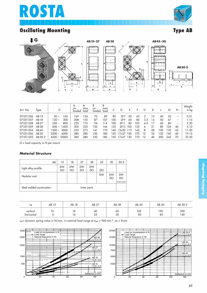
Oscillating Mounting Type AB
cd AB 15 AB 18 AB 27 AB 38 AB 45 AB 50 AB 50-2
vertical 10 18 40 60 100 190 320horizontal 6 14 25 30 50 85 140
cd = dynamic spring value in N/mm, in nominal load range at nerr = 960 min–1, sw = 8 mm
20 000
15 000
10 000
7500
5000
2500
0 30 60 90 120 150Deflection in mm
AB 50-2f 2.1– 2.4
AB 50f 2.1– 2.4
AB 45f 2.3 – 2.8
Load on compression in NLoad rangeNatural frequency in Hzff
500
100
AB 38f 2.4 – 3
AB 27f 2.7 – 3.7
AB 18f 2.6 – 3.6
Deflection in mm
AB 15f 2.8 – 4.3
806040200
1000
2000
3000
4000Load on compression in NLoad rangeNatural frequency in Hz
WeightArt. No. Type G A B C C D E F H K L M N in kg
07 051 056 AB 15 1350 – 12160 169 124 70 89 80 Ø 7 50 65 3 10 40 52 – 0.5107 051 057 AB 18 1120 – 0300 208 155 87 107 100 Ø 9 60 80 3.5 14 50 67 – 1.1507 051 058 AB 27 1250 – 3800 235 175 94 114 100 Ø11 80 105 4.5 17 60 80 – 2.2007 051 059 AB 38 2600 – 1600 305 235 120 144 125 Ø13 100 125 6 21 80 104 40 5.1007 051 054 AB 45 1200 – 3000 353 273 141 170 140 13x20 115 145 8 28 100 132 65 11.5007 051 006 AB 50 2500 – 16000 380 280 150 180 150 17x27 130 170 12 35 120 160 60 19.12 07 051 055 AB 50-2 4200 – 10000 380 280 150 180 150 17x27 130 170 12 40 200 245 70 32.20
Aun-loaded
A max.load
Bun-loaded
B max.load
G = load capacity in N per mount
AB45–50
AB50-2
AB15–27 AB38
➡
G
Material Structure
Light alloy profile
Nodular cast
Steel welded construction
AB 15 18 27 38 45 50 50-2
DW DW DW DWDO DO DO DO DO
DW DW DWDO DO
Inner parts
Inner parts
Osc
illa
ting
Mou
ntin
gs
Osc
illa
ting
Mou
ntin
gs
ROSTA
70
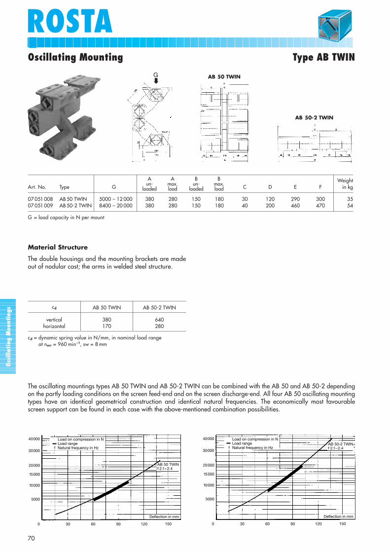
WeightArt. No. Type GA B C C D E F in kg
07 051 008 AB 50 TWIN 5000 – 12 000 380 280 150 180 30 120 290 300 3507 051 009 AB 50-2 TWIN 8400 – 20 000 380 280 150 180 40 200 460 470 54
G = load capacity in N per mount
cd AB 50 TWIN AB 50-2 TWIN
vertical 380 640horizontal 170 280
cd = dynamic spring value in N/mm, in nominal load range at nerr = 960 min–1, sw = 8 mm
AB 50 TWIN
AB 50-2 TWIN
The oscillating mountings types AB 50 TWIN and AB 50-2 TWIN can be combined with the AB 50 and AB 50-2 dependingon the partly loading conditions on the screen feed-end and on the screen discharge-end. All four AB 50 oscillating mountingtypes have an identical geometrical construction and identical natural frequencies. The economically most favourablescreen support can be found in each case with the above-mentioned combination possibilities.
0 30 60 90 120
5000
AB 50 TWINf 2.1–2.4
Deflection in mm
10000
15000
20000
30000
40000
150
f
Load on compression in NLoad rangeNatural frequency in Hz f
Load on compression in NLoad rangeNatural frequency in Hz
0 30 60 90 120
5000
AB 50-2 TWINf 2.1–2.4
Deflection in mm
10000
15000
20000
30000
40000
150
Oscillating Mounting Type AB TWIN
Material Structure
The double housings and the mounting brackets are madeout of nodular cast; the arms in welded steel structure.
Aun-
loaded
A max.load
Bun-
loaded
B max.load
➡G
Osc
illa
ting
Mou
ntin
gs
ROSTAROSTA
71
Oscillating Mounting Type AB-D
WeightArt. No. Type G A B B C D E F H I J K L M in kg
07 281 000 AB-D 18 500 – 11200 137 117 115 61 50 12.5 90 3 9.5 9.5 74 31 30 1.307 281 001 AB-D 27 1000 – 12500 184 157 150 93 80 15.5 120 4 9.5 11.5 116 44 50 2.907 281 002 AB-D 38 2000 – 14000 244 209 185 118 100 17.5 150 5 11.5 13.5 147 60 70 7.507 281 003 AB-D 45 3000 – 16000 298 252 220 132 110 25.5 170 6 13.5 18.5 168 73 80 11.507 281 004 AB-D 50 4000 – 19000 329 278 235 142 120 25.5 185 6 13.5 18.5 166 78 90 22.007 281 005 AB-D 50-1.6 8000 – 12000 329 278 235 186 160 25.5 185 8 13.5 18.5 214 78 90 25.507 281 006 AB-D 50-2 11000 – 16000 329 278 235 226 200 25.5 185 8 13.5 18.5 260 78 90 29.0
G = load capacity in N per mount* Values: setting included
Aun-
loaded
A*max.load
Owing to the significantly shorter lever arm connections (in the double rubber suspension unit) the AB-D provides a farhigher loading capacity compared with the type AB oscillating mountings with extremely compact construction. Thelinear cushioning produced under load, however, is sufficient to ensure the respectably low natural frequency of thisoscillating mounting of approx. 3.5 Hz. At the oscillating machine frequency of approx. 16 Hz, the mounting provides aninsulation efficiency of approx. 96 %.
AB-D 18/f 4.4–6.1
AB-D 38/f 3.4–4.3
AB-D 27/f 3.9–5.4
Deflection in mm
f
Load on compression in NLoad rangeNatural frequency in Hz
AB-D 50-2/f 2.8–3.5
AB-D 50/f 2.9–3.7
Belastung auf Druck in NBelastungsbereichEigenfrequenz in Hzf
AB-D 45/f 3.1–3.7
f
AB-D 50-1.6/f 2.9–3.6
0
Load on compression in NLoad rangeNatural frequency in Hz
Deflection in mm
max. sw cd
Art. No. Type nerr = 740 min–1 nerr = 980 min–1 nerr = 1460 min–1 vertical at sw horizontal
07 281 000 AB-D 18 5 4 3 100 4 2007 281 001 AB-D 27 6 5 4 160 4 3507 281 002 AB-D 38 8 7 5 185 6 4007 281 003 AB-D 45 10 8 6 230 8 7007 281 004 AB-D 50 12 10 8 310 8 12007 281 005 AB-D 50-1.6 12 10 8 430 8 16007 281 006 AB-D 50-2 12 10 8 540 8 198
max. sw = max. amplitude in mmcd = dynamic spring value in N/mm, in nominal load range at nerr = 980 min–1 (please respect max. amplitude in mm).
Material StructureThe double housings of the sizes 18 to 45 are made out of light alloyprofiles, the ones from size 50 in nodular cast; the inner squares in lightalloy profiles; fixation brackets in steel.
➡G
Osc
illa
ting
Mou
ntin
gs
72
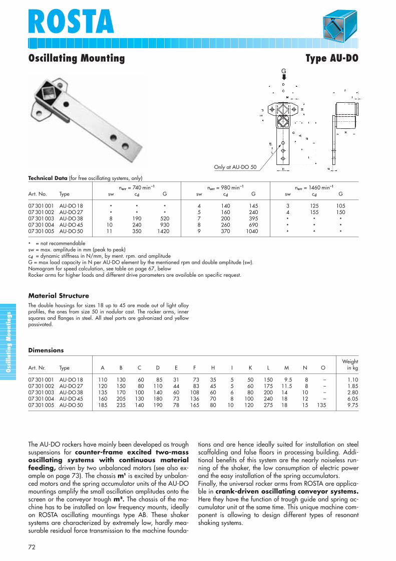
ROSTAOscillating Mounting Type AU-DO
Technical Data (for free oscillating systems, only)
nerr = 740 min–1 nerr = 980 min–1 nerr = 1460 min–1
Art. No. Type sw cd G sw cd G sw cd G
07 301 001 AU-DO 18 * * * 4.0 140 145 3.0 125 10507 301 002 AU-DO 27 * * * 5 160 240 4 155 15007 301 003 AU-DO 38 8 190 520 7 200 395 *0 * *07 301 004 AU-DO 45 10 240 930 8 260 690 *0 * *07 301 005 AU-DO 50 11 350 1420 9 370 1040 *0 * *
* = not recommendablesw = max. amplitude in mm (peak to peak)cd = dynamic stiffness in N/mm, by ment. rpm. and amplitudeG = max load capacity in N per AU-DO element by the mentioned rpm and double amplitude (sw).Nomogram for speed calculation, see table on page 67, belowRocker arms for higher loads and different drive parameters are available on specific request.
The AU-DO rockers have mainly been developed as troughsuspensions for counter-frame excited two-massoscillating systems with continuous materialfeeding, driven by two unbalanced motors (see also ex-ample on page 73). The chassis m1 is excited by unbalan-ced motors and the spring accumulator units of the AU-DOmountings amplify the small oscillation amplitudes onto thescreen or the conveyor trough m2. The chassis of the ma-chine has to be installed on low frequency mounts, ideallyon ROSTA oscillating mountings type AB. These shaker systems are characterized by extremely low, hardly mea-surable residual force transmission to the machine founda-
tions and are hence ideally suited for installation on steelscaffolding and false floors in processing building. Addi-tional benefits of this system are the nearly noiseless run-ning of the shaker, the low consumption of electric powerand the easy installation of the spring accumulators.Finally, the universal rocker arms from ROSTA are applica-ble in crank-driven oscillating conveyor systems.Here they have the function of trough guide and spring ac-cumulator unit at the same time. This unique machine com-ponent is allowing to design different types of resonantshaking systems.
Material StructureThe double housings for sizes 18 up to 45 are made out of light alloyprofiles, the ones from size 50 in nodular cast. The rocker arms, innersquares and flanges in steel. All steel parts are galvanized and yellowpassivated.
➡G
Only at AU-DO 50
WeightArt. Nr. Type A B C D E F H I K L M N O in kg
07 301 001 AU-DO 18 110 130 60 85 31 73 35 5 50 150 9.5 8 – 1.1007 301 002 AU-DO 27 120 150 80 110 44 83 45 5 60 175 11.5 8 – 1.8507 301 003 AU-DO 38 135 170 100 140 60 108 60 6 80 200 14.5 10 – 2.8007 301 004 AU-DO 45 160 205 130 180 73 136 70 8 100 240 18.5 12 – 6.0507 301 005 AU-DO 50 185 235 140 190 78 165 80 10 120 275 18.5 15 135 9.75
Dimensions
Oscillating Mounting Type AU-DO
73
ROSTA
Osc
illa
ting
Mou
ntin
gs
Feeding direction
m1
m2
30°
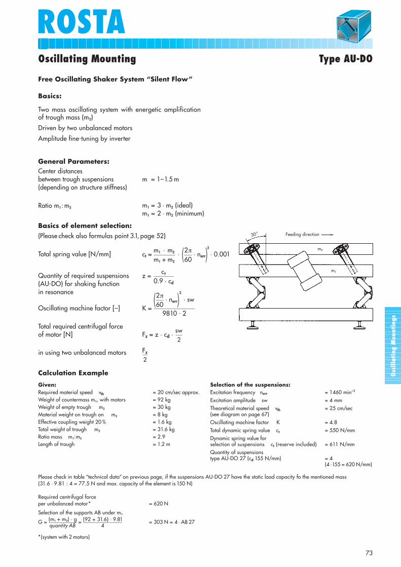
Selection of the suspensions:Excitation frequency nerr = 1460 min–1
Excitation amplitude sw = 4 mmTheoretical material speed vth = 25 cm/sec (see diagram on page 67)Oscillating machine factor K = 4.8Total dynamic spring value ct = 550 N/mmDynamic spring value forselection of suspensions ct (reserve included) = 611 N/mmQuantity of suspensions type AU-DO 27 (cd 155 N/mm) = 4
(4 ·155 = 620 N/mm)
Calculation Example
Given:Required material speed vth = 20 cm/sec approx.Weight of countermass m1, with motors = 92 kgWeight of empty trough m2 = 30 kgMaterial weight on trough on m2 = 8 kgEffective coupling weight 20 % = 1.6 kgTotal weight of trough m2 = 31.6 kgRatio mass m1:m2 = 2.9Length of trough = 1.2 m
General Parameters:Center distances between trough suspensions(depending on structure stiffness)
Ratio m1: m2
Basics of element selection:(Please check also formulas point 3.1, page 52)
Total spring value [N/mm]
Quantity of required suspensions (AU-DO) for shaking function in resonance
Oscillating machine factor [–]
Total required centrifugal forceof motor [N]
in using two unbalanced motors
m1 + m2 60ct =
m1 · m2 · (2π· nerr)
2
· 0.001
0.9 · cdz =
ct
9810 · 2K =
(2π· nerr)
2
· sw60
Fz = z · cd · sw
Fz
m1 = 3 · m2 (ideal)m1 = 2 · m2 (minimum)
m = 1–1.5 m
2
2
Free Oscillating Shaker System “Silent Flow”
Basics:
Two mass oscillating system with energetic amplification of trough mass (m2)
Driven by two unbalanced motors
Amplitude fine-tuning by inverter
Please check in table “technical data” on previous page, if the suspensions AU-DO 27 have the static load capacity fo the mentioned mass (31.6 · 9.81 : 4 = 77.5 N and max. capacity of the element is 150 N)
Required centrifugal force per unbalanced motor* = 620 N
Selection of the supports AB under m1
G = (m1 + m2) · g = (92 + 31.6) · 9.81 = 303 N = 4 · AB 27quantity AB 4
*(system with 2 motors)
Osc
illa
ting
Mou
ntin
gs
74
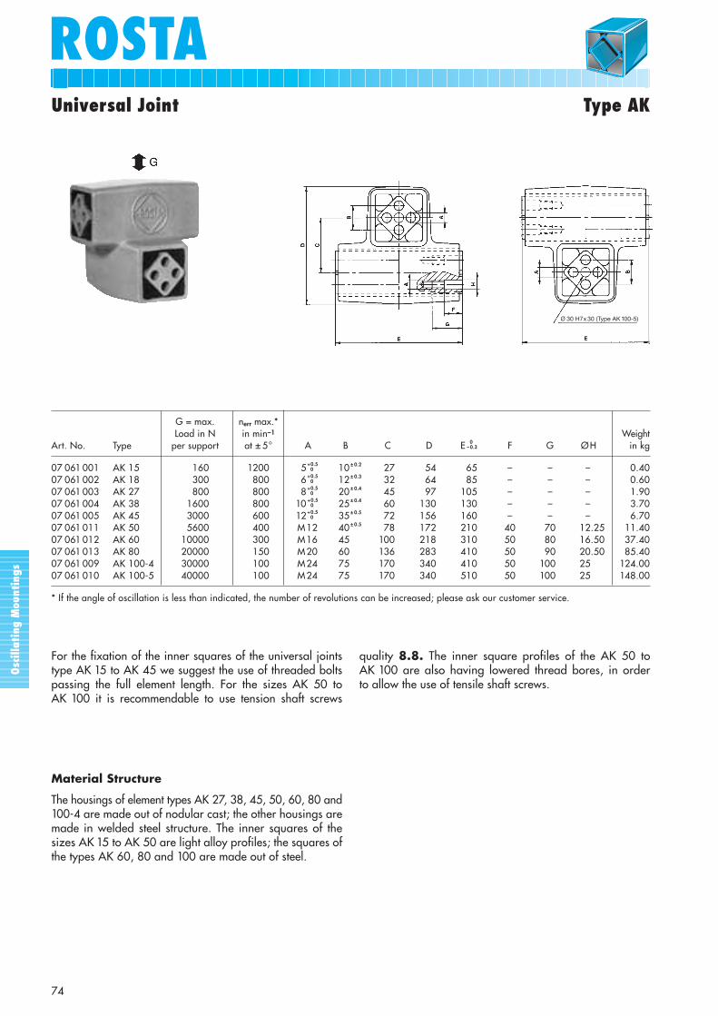
ROSTAUniversal Joint Type AK
G = max. nerr max.*Load in N in min–1 Weight
Art. No. Type per support at ± 5° A B C D E 0–0.3 F G ØH in kg
07 061 001 AK 15 160 1200 5 +0.50 10 ± 0.2 27 54 65 – – – 0.40
07 061 002 AK 18 300 800 6 +0.50 12 ± 0.3 32 64 85 – – – 0.60
07 061 003 AK 27 800 800 8 +0.50 20 ± 0.4 45 97 105 – – – 1.90
07 061 004 AK 38 1600 800 10 +0.50 25 ± 0.4 60 130 130 – – – 3.70
07 061 005 AK 45 3000 600 12 +0.50 35 ± 0.5 72 156 160 – – – 6.70
07 061 011 AK 50 5600 400 M12 40 ± 0.5 78 172 210 40 70 12.25 11.4007 061 012 AK 60 10000 300 M16 45 ± 0.5 100 218 310 50 80 16.50 37.4007 061 013 AK 80 20000 150 M20 60 ± 0.5 136 283 410 50 90 20.50 85.4007 061 009 AK 100-4 30000 100 M24 75 ± 0.5 170 340 410 50 100 25.50 124.0007 061 010 AK 100-5 40000 100 M24 75 ± 0.5 170 340 510 50 100 25.50 148.00
* If the angle of oscillation is less than indicated, the number of revolutions can be increased; please ask our customer service.
Material Structure
The housings of element types AK 27, 38, 45, 50, 60, 80 and100-4 are made out of nodular cast; the other housings aremade in welded steel structure. The inner squares of thesizes AK 15 to AK 50 are light alloy profiles; the squares ofthe types AK 60, 80 and 100 are made out of steel.
For the fixation of the inner squares of the universal jointstype AK 15 to AK 45 we suggest the use of threaded boltspassing the full element length. For the sizes AK 50 to AK 100 it is recommendable to use tension shaft screws
quality 8.8. The inner square profiles of the AK 50 to AK 100 are also having lowered thread bores, in order to allow the use of tensile shaft screws.
Ø 30 H7x 30 (Type AK 100-5)
Osc
illa
ting
Mou
ntin
gs
75
ROSTAUniversal Joint Type AK
Joint Support
In order to obtain a regular torsional load on all elementsand a harmonic circular motion, the inner elements “E” ofthe universal joints must be fitted offset 90° to the oneunderneath. The connection between the two universaljoints AK and the support ready to be installed must beadapted to the corresponding installation height, and beprovided by the customer. For the fixing of the inner squaresections we recommend to use hexagonal shaft screws of8.8 quality. For the size AK 50 or bigger there are threadsborings on the inner squares of the elements.
Typical Calculation (“Upright” Version)
Total oscillating mass m = 1600 kgEccentric radius R = 25 mmSupport height X = 800 mmOscillating angle α = 3.6°Speed nerr = 230 min–1
Number of universal joint supports z = 4 pieces
Max. dynamic load per support G =m · g · 1.25*
= 1600 · 9.81 · 1.25* = 4905 N
Selected: 4 supports with each 2 AK 50 elements = 8 AK 50
* = Due to the instability of the “upright” sifters, we in-clude a security factor of 1.25 for the calculation of theAK elements.
z
4
Suspended Version
We recommend our AK universal joints also for this version,which is especially used for screening tables and tumblinggyrators. Usually unbalanced motors are used to drive the screens, causing the discharge-end to oscillate freely(tumbling movements). The universal joints are undertraction. However, the actual units remain the same. Thisversion doesn’t require a security factor.
Installation Guidelines
The oscillation angle α must not exceed 10° (± 5°). Other-wise the elements “E” must be set with longer centerdistance (distance “X”). In order to eliminate the tilting andcardanic movements, the upper elements of the universaljoint support are placed at the height close to the centre ofgravity S of the screen box.
Osc
illa
ting
Mou
ntin
gs
76
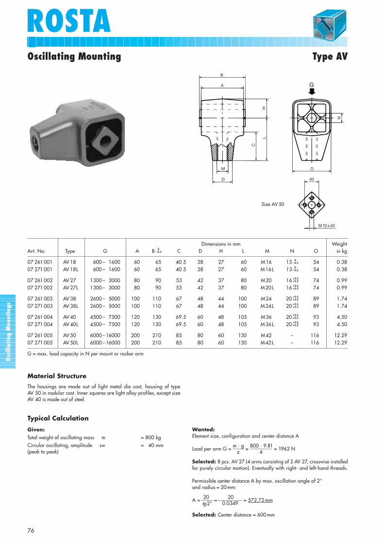
ROSTAOscillating Mounting Type AV
M12x40
40
O
N
HL
C
B
A
M
D
Bei Grösse AV 50Size AV 50
G
Wanted:Element size, configuration and center distance A
Load per arm G = m · g = 800 · 9.81 = 1962 N
Selected: 8 pcs. AV 27 (4 arms consisting of 2 AV 27, crosswise installedfor purely circular motion). Eventually with right- and left-hand threads.
Permissible center distance A by max. oscillation angle of 2°and radius = 20 mm:
A = 20 = 20 = 572.72 mm
Selected: Center distance = 600 mm
Typical Calculation
Given:Total weight of oscillating mass m = 800 kgCircular oscillating, amplitude sw = 40 mm(peak to peak) z 4
tg2° 0.0349
Material Structure
The housings are made out of light metal die cast, housing of type AV 50 in nodular cast. Inner squares are light alloy profiles, except sizeAV 40 is made out of steel.
Dimensions in mm WeightArt. No. Type G A B 0
– 0.3 C D H L M N O in kg
07 261 001 AV 18 600 – 1600 60 65 40.5 28 27 60 M16L 13 0–0.2 54 0.38
07 271 001 AV 18L 600 – 1600 60 65 40.5 28 27 60 M16L 13 0–0.2 54 0.38
07 261 002 AV 27 1300 – 3000 80 90 53 42 37 80 M20L 16 + 0.5+ 0.3 74 0.99
07 271 002 AV 27L 1300 – 3000 80 90 53 42 37 80 M20L 16 + 0.5+ 0.3 74 0.99
07 261 003 AV 38 2600 – 5000 100 110 67 48 44 100 M24L 20 + 0.5+ 0.2 89 1.74
07 271 003 AV 38L 2600 – 5000 100 110 67 48 44 100 M24L 20 + 0.5+ 0.2 89 1.74
07 261 004 AV 40 4500 – 7500 120 130 69.5 60 48 105 M36L 20 + 0.5+ 0.2 93 4.50
07 271 004 AV 40L 4500 – 7500 120 130 69.5 60 48 105 M36L 20 + 0.5+ 0.2 93 4.50
07 261 005 AV 50 6000 – 16000 200 210 85 80 60 130 M42L – 116 12.2907 271 005 AV 50L 6000 – 16000 200 210 85 80 60 130 M42L – 116 12.29
G = max. load capacity in N per mount or rocker arm
Osc
illa
ting
Mou
ntin
gs
77
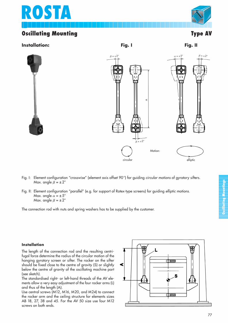
ROSTAOscillating Mounting Type AV
Installation
The length of the connection rod and the resulting centri-fugal force determine the radius of the circular motion of thehanging gyratory screen or sifter. The rocker on the siftershould be fixed close to the centre of gravity (S) or slightlybelow the centre of gravity of the oscillating machine part(see sketch). The standardised right- or left-hand threads of the AV ele-ments allow a very easy adjustment of the four rocker arms (L)and thus of the length (A). Use central screws (M12, M16, M20, and M24) to connectthe rocker arm and the ceiling structure for elements sizesAB 18, 27, 38 and 45. For the AV 50 size use four M12screws on both ends.
Fig. I: Element configuration “crosswise” (element axis offset 90°) for guiding circular motions of gyratory sifters.Max. angle � = ± 2°
Fig. II: Element configuration “parallel” (e.g. for support of Rotex-type screens) for guiding elliptic motions.Max. angle � = ± 5°Max. angle � = ± 2°
The connection rod with nuts and spring washers has to be supplied by the customer.
� = ± 2°
� = ± 2°
� = ± 5° � = ± 2°
A
Installation: Fig. I Fig. II
Motion:
circular elliptic
Osc
illa
ting
Mou
ntin
gs
78
ROSTA
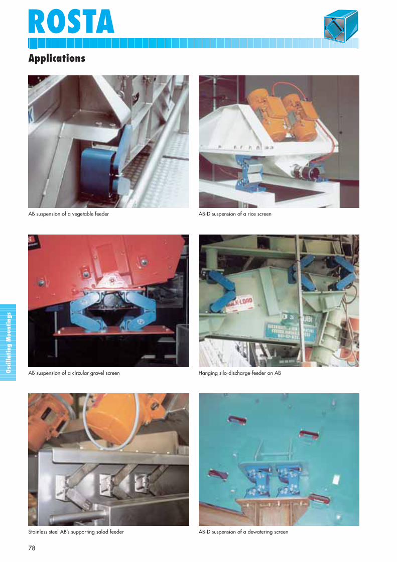
AB suspension of a circular gravel screen Hanging silo-discharge-feeder on AB
AB-D suspension of a rice screenAB suspension of a vegetable feeder
Stainless steel AB’s supporting salad feeder AB-D suspension of a dewatering screen
Applications


![IP Event Dampening - Cisco...dampening [half-life-period reuse-threshold] Enablesinterfacedampening. [suppress-threshold max-suppress [restart-penalty]] Step4 •Enteringthedampening](https://img.pdfslide.us/doc/110x75/612e12771ecc515869429546/ip-event-dampening-cisco-dampening-half-life-period-reuse-threshold-enablesinterfacedampening.jpg)