Embed Size (px)
Citation preview
PTT-1BPTT-1B Position Sensing Cylinders
36HG
PTT-1BPosition S
ensing Cylinders
PTT-1
B37HG
21 MPa position sensingcylinders using absolutemethod
Standard Specifications
General purpose type
21 MPa
Cap side and rod side (Rod A): 26.5 MPa
Rod side (Rod B): 24.5 MPa
31.5 MPa
Metal fitting system
Cap side: 0.3 MPa or less
Rod side: Rod B: 0.45 MPa or less
Rod side: Rod A: 0.6 MPa or less
f50 to 63: 8 to 400mm/s
f80 to 125: 8 to 300mm/s
f140 to 160: 8 to 200mm/s
Standard type -10℃ to +80℃(No freezing)
Petroleum-based fluid
(When using another fluid, refer to the
table of fluid adaptability.)
JIS 6g/6H
SD・LA・FA・TA・TC
Rod B, rod A
Standard: Nylon tarpaulin
Semi-standard: Chloroprene or Conex
T-end, Y-end (with pin), lock nut
Type
Nominal pressure
Proof test pressure
Working speed range
Structure of cushioning
Adaptable fluid
Tolerance for thread
Tolerance of stroke
Mounting style
Rod series
Boots
Rod endattachments
Accessories
Working temperature range(ambient temperature)
Maximum allowablepressure
Minimum operatingpressure
0 to 100 mm
101 to 250mm:
251 to 630mm:
631 to 1000mm:
1001 to 1600mm:
1601 to 2000mm:
+0.8 0+1.0 0
+1.25 0
+1.4 0+1.6 0
+1.8 0
Terminologies
●The position sensor applying a magneto-striction phenomenon enables high-accuracy absolute position detection.●No necessary to adjusting the original position, and position correction is not required.●Space-saving design and easy to install.
Nominal pressurePressure given to a cylinder for convenience of naming.Maximum allowable pressureMaximum allowable pressure generated in a cylinder (surge pressure, etc.).Proof test pressureTest pressure against which a cylinder can withstand without unreliable performance at the return to nominal pressure.Minimum operating pressureMinimum pressure at which cylinder installed horizontally operates under no load.
●The hydraulic pressure generated in a cylinder due to the inertia of load must be lower than the maximum allowable pressure.●Some piston rods have a 13- to 16-mm dia. through hole. If the wall thickness is reduced or the wall is broken when a hex. screw is fitted, oil leakage can occur. Fit the screw carefully.●The working temperature range depends on the seal material. For details, refer to the selection materials at the beginning of this catalog.●In the case that the lock nut is attached to the piston rod end thread part, increase the thread length (dimension A).●Conex, material of the boots, is the registered trademark of Teijin Limited.
Notes)
Product Lineup
General purpose type
Unit: mm
StandardtypePTT-1B
f50 f63 f80 f100 f125 f140 f160
Rod B
Rod A
Detector Specifications
Power supply
Linearity
Resolution
Repeatability
Frequency characteristics
Working temperature range
Impact resistance
Vibration resistance
Protective structure
Standard
semi-standard
24 V DC±2V 0.05A
±0.025%FS or ±75 μmTYP
±0.01%FS or less or ±30 μm or less
±0.01%FS or less or ±30 μm or less
40 ppmFS/ or less or 12 μm/ or less
Current output of 4 to 20 mA, load resistance of 500 Ω or less
Voltage output: 0 to 10 V
Load current: 5 mA max. Load resistance: 2 kΩ min.
Scanning frequency 1 kHz
-20℃ to +80℃
50G 2m1S
6 G or 40 Hz2mmPP
IP67(10kPa, 30min)
Shield to be connected to 0 V by user0 V and COM are connected internally.
OMRON XS2C-D4S1
Outer diameter: 5 to 6 mmWire size: 0.18 to 0.75 mm²
Supplied connector
Applicable cable(not supplied)
Pin No.
1
2
3
4
Signal
24 V DC
0V
Output
COM
Connection
Acc
urac
yO
utpu
t
Stroke Range
Bore Stroke
to 1500f50 to f160
Unit: mm
* Above shown are the specifications for the sensor only.* A larger value of two values of each accuracy item isapplicable.
Cushion Stroke Length
Cushion ringlength L
Cushion ringparallel part lengthr
25
30
30
7
8
12
f50・f63
f80 to f125
f140 to f160
Unit: mm
Series Variation Rod dia.Type
Doubleactingsinglerod
Temperaturecharacteristics
Bore
The cushion stroke lengths in case of cylinders used up to the stroke end. In the case that a cylinder is not used up to the stroke end, and it is stopped 5 mm or more before the stroke end, the cushioning effect will be weakened.
●The above strokes indicate the maximum available strokes for the standard type. Contact us for longer strokes.●For the rod buckling, check with the buckling chart in the selection materials.
●In the mounted state on the cylinder, the above accuracy cannot be assured due to deformation of cylinder elements caused by pressure and load. For the repeatability under the same conditions, a value close to the above accuracy can be obtained.●The output is 4.0 to 4.5 mA or 0 to 0.3 V at the cylinder retracting end and 12 to 20 mA or 5 to 10 V at the cylinder advancing end. (At some cylinder strokes, part of the sensor effective length may not be used.) Set the controller conditions based on the actual output at the cylinder advancing and retracting ends.
L
R
L
R
21 MPa Position SensingHydraulic Cylinder
21 MPa Position SensingHydraulic Cylinder
PTT-1BPTT-1B Position Sensing Cylinders
38HG
PTT-1BPosition S
ensing Cylinders
PTT-1
B39HG
General Purpose Type
Mounting style
SD style (basic style)SD
TA style (rod trunnion)TALA style (side lugs)LA
TC style(Intermediate trunnion)
TCFA style (rod flange)FA
Semi-standard range●With boots●Change of piston rod end●Change of TC accessory position●Plated cylinder tube(hard chrome plating thickness: 0.02 mm)●Specification of working fluid(water-glycol fluid)●Specification of dimension BB(extension of tie rod)
●Standard type PTT-1B - - G KTLA2 50
1 2 3 6
Nitrile rubberUrethane rubberFluorocarbonHNBR
NoneG
Rc threadG thread
Note) For 140 mm and 160 mm borecylinders with rod A, only [1] and[2] can be used.
B R H N
With cushions on both endsWith cushion on rod sideWith cushion on cap sideNo cushion
A BRod ARod B
100B
Mounting style
B A B
The rod end thread length(dimension A) is longer.
J
Double acting single rod
PTT-1B: Standard type
Cylinder bore (mm)Standard typef50・f63・f80・f100・f125・f140・f160
Note) 50 mm bore cylinderscan use only the rod A.
J JN JK
Nylon tarpaulinChloropreneConex
K Long thread with lock nut
T YRod eye (T-end)Rod clevis (Y-end)
Cushion valve position (A, B, C, D, 0)
Port position (A, B, C, D)
Cylinder stroke (mm)
Type❶
Cylinder bore❹
Rod end attachment11
Lock nut12
Boots 13
Port type❽
Seal material❷
Mounting style ❸
Rod type❺
Cushioning❻
Port position❾
Cushion valve position10
Stroke❼
The item enclosed by broken line needs not to be entered, if unnecessary. Semi-standardspecification
The rod end attachments are dedicated to the rod B. To use them for the rod A, give instructions to change the rod end thread length to that of the rod B.
●In the case that the cushion is not equipped, the cushion valve position is “0”.●In the case of the mounting style LA, the port and cushion are positioned on A, B or D.
Weight Table Unit: kg
ABABABABABABAB
8.1-
12.712.119.518.529.928.153.150.875.472.0
102.698.5
0.019-
0.0290.0240.0430.0360.0650.0540.1040.0840.1310.1090.1660.142
φ50
φ63
φ80
φ100
φ125
φ140
φ160
Bore(mm)
Rodtype
Basic weight(SD style)
Mounting accessoryadditional weight
Rod end attachment weight
Rod eye(T-end)
Rod clevis(Y-end)LA FA TA TC
Nut only StandardWith lock nut
0.78-
1.121.121.571.572.442.444.464.468.188.18
13.2113.21
1.24-
1.661.502.552.095.114.237.216.198.715.76
13.1010.16
0.28-
0.540.541.171.172.872.815.015.017.437.43
12.0212.02
1.08-
1.801.803.253.257.027.02
14.1514.1520.6120.6126.1426.14
-1.67-
2.51-
3.77-
7.47-
12.41-
19.17-
26.97
-2.30-
3.97-
6.54-
12.62-
22.96-
33.75-
46.72
0.220.110.480.220.910.481.840.913.231.845.162.506.223.23
0.360.180.810.361.480.813.101.485.803.109.604.42
11.145.80
Notes)
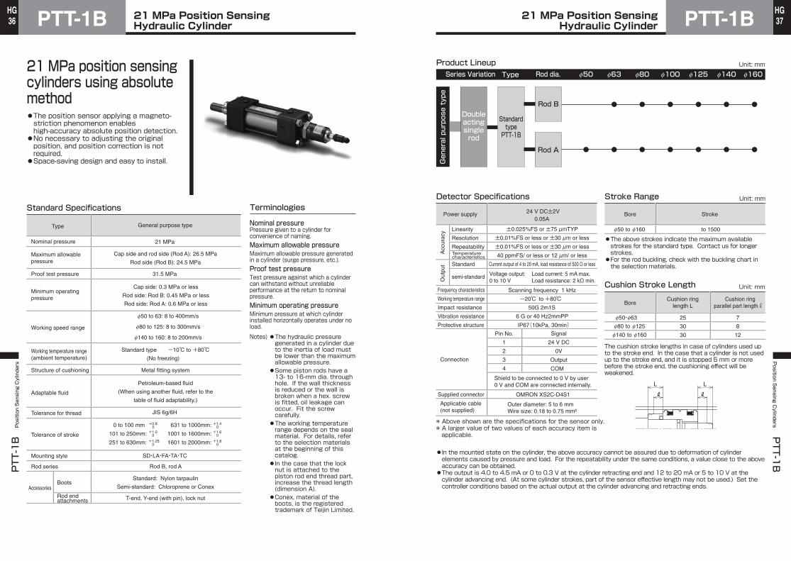
Sectional Drawing
Note) The structure differs slightly depending on the cylinder bore and the position sensor model.
Application Example
Magnet Sensor probe
Position sensor Connector
Principle of Operation of Position Sensor
Additional weightper mm of stroke
●See the “With lock nut ‒ Standard” column when the nut symbol is K. The values include the weight for the increase in screw length.●The rod eye and rod clevis are dedicated to the rod B.When the rod A is used, change the rod end thread diameter to that of the rod B.
◎The cylinder position and operation can be checked on the counter, and position adjustment and inching can be easily performed by manual operation.◎When combined with a personal computer or a microprocessor, the cylinder can be decelerated and stopped at any position.
Counter
Hydraulic circuit
Programmablecontroller
Direct analog inputdevices, such asservo valve
A/D converter
PTT-1B
Microprocessor
PQCPA (indicator with multi-point output function)
Sonic wave
Magnetostrictive curve
Axial magnetic field
Circumferential magnetic fieldA
S
N
A The figure shows the basic principle.When a current pulse shown by arrow A is given to the magnetostrictive curve, a circumferential magnetic field is generated on the magnetostrictive curve.When a magnet is positioned as shown in the figure, an axial magnetic field is given only to the position, and a diagonal magnetic field as shown by the dotted line is generated, thereby causing torsion in this part of the magnetostrictive curve. Since this torsion is a kind of vibration, it propagates at the sonic speed on the magnetostrictive curve which is a metallic tube.PTT-1B Series uses absolute type position sensors which measure the propagation time at the supersonic speed to find the magnet position.
21 MPa Position SensingHydraulic Cylinder
21 MPa Position SensingHydraulic Cylinder
● How to order
PTT-1BPTT-1B Position Sensing Cylinders
40HG
PTT-1BPosition S
ensing Cylinders
PTT-1
B41HG
Standard Specifications
±999999
24 V DC ±10%0 to 50℃ (No freezing)
35 to 85%RH (No condensing)
P-UC-APCQP
-
-
A-UC-APCQP
1 kHz
Voltage output Note)
Open collector Max. rating: 50 V DC, 50 mA(Provided with multi-point output function (5 points) to enable to individually
set the upper and lower limits and pulse position correcting function)
1000 times/sec
10 times/sec
Display by fluorescent display tube
No-voltage input (reed sensor/solid state sensor)
Line driver output
Voltage input 0 to 10 VVoltage input 1 to 5 V
Current input 4 to 20 mA
Open collector inputDifferential input (line driver input)
12 V voltage input24 V voltage input
200 kHz
±0.02%FS
Type Analog
Analog voltage/analog current
Stroke×1/10000
Phase AB
Pulse
Model number
Applicable input signals
Display range
Resolution
Response frequency
Linearity
Monitor output
Sampling speed
Display speed
Display method
Control input
Power supply voltage
Ambient temperature
Ambient humidity
Signals
Control output
Note) The monitor output at current input (4 to 20 mA) is voltage output of 1 to 5 V.
Type Analog input Pulse input
Display of positionBank switching
Multi-point outputPositional data hold
Display of positionBank switching
Multi-point outputPositional data hold
0 setting signalCorrecting function
Modelnumber
Functions
A-A-UC-APCQPV-A-UC-APCQP
-
- -
21-P-UC-APCQP42-P-UC-APCQP00-P-UC-APCQP
Function TableSeries Detection method
Absolute method
Linear pulse encoder
Signal type
Analog type (1 to 5 V)
Encoder type
Analog type(4 to 20 mA, 0 to 10 V)
List of Applicable Actuators
Note) For the details of each cylinder, refer to thesection of each series.
B1-NTPB1-HTPB1-TTPA1-RSP
3-P538-P078-P041
PQCPA Series dedicatedto analog/pulse output fromposition sensing cylinders●Environmentally-friendly lead-free indicator.●Analog input and pulse input types are available.●Provided with multi-point output function (5 points) as a standard function to enable to individually set the upper and lower limits.Note 1)●A 16-bit AD converter is provided to realize high resolution. (Analog input type)●Provided with a counter with a response frequency of 200 kHz (Pulse input type)●Provided with a pulse position correcting function.Note 2)
Note 1) Setting the bank switching enables to use the multi-output function of up to 15 points.
Note 2) Position correction can be made by mounting a cylinder sensor. Positional error caused by slippage of the encoder is eliminated.
Position Indicator●Analog input
APCQP - AUC -- A
AVCurrent inputVoltage input
Series
Seriesq
Input methodw
Type
Input method
Type
e
●Pulse input
APCQP - 21UC -- P
214200
12 V open collector input, 12 V voltage input24 V open collector input, 24 V voltage inputDifferential input
q w e
Note) Cylinders do not come with indicators ofdifferential input type 00 . (Specification touse the indicator in stand-alone state)
Dimensional Drawings Supplied Connector
CN1 connector(for input of measuring sensor signal)
●
CN4 connector(for power supply)
●
CN2 connector(for output of measuring sensor signal)
●
CN3 connector(for control input/output)
●
Front face Rear face
CN5 HOLD
MODE
SET
RST
→↓
←↑ERROR HOLDPOWER
PQC series control unit PQCPA
Front view
Rear view
Top view
Side view
Panel cutting dimensions
64
140
60
78.51.5
62
122
4-f3.5
CN1 CN2 CN4
CN3
130
54
*When fitting the connectors,keep a space of at least200 mm at the rear.
120
Display (fluorescent display tube)
Status indication lamp block (LED) Operation key block
CN1 connector(for input of measuring sensor signal)
CN2 connector(for output of measuring sensor signal)
CN3 connector(for control input/output)
CN4 connector(for power supply)
21 MPa Position Sensing Hydraulic CylinderPosition Indicator with Multi-point Output
21 MPa Position Sensing Hydraulic CylinderPosition Indicator with Multi-point Output
● How to order
PTT-1BPTT-1B Position Sensing Cylinders
42HG
PTT-1BPosition S
ensing Cylinders
PTT-1
B43HG
PQCPA - 01CV1
PQCPA - IO
-
010510
1m5m10m
How to order cable between sensor and indicator
* When ordering a cable, confirm the series name of the actuator on the sensor side.Some models cannot be connected.
* After wiring, connect the indicator side connector to the CN1 connector on the indicator.
Applicable actuators: PTH-1B/PTN-1B/PTT-1B
Applicable actuators: 35P-3/70P-8/140P-8
Applicable actuators: PSR-1A
CN3 Half-pitch connectorNote) Only the CN3 half-pitch connector is supplied as a standard accessory.
If you need the connector with a cable, place an order for the connector.
How to order I/O cable
*The I/O cable is 5 m long.External devices(programmable controller, etc.)
CV1CV2CV3
PTH-1・PTN-1B・PTT-1B35P-3・70P-8・140P-8PSR-1A
Seriesq
Applicable cylinderw
Cable lengthe
PQCPA-CV1- Cable length
PQCPA-CV2- Cable length
PQCPA-CV3- Cable length
CN5 HOLD
MODE
SET
RST
→↓
←↑ERROR HOLDPOWER
PQC series control unit PQCPA
PQCPA-CU-*
CN5 HOLD
MODE
SET
RST
→↓
←↑ERROR HOLDPOWER
PQC series control unit PQCPA
PQCPA-CU-*
Cable length (1 m, 5 m, 10 m)
Cable length (1 m, 5 m, 10 m)
Cable length (1 m, 5 m, 10 m)
Amplifier
AWG24×4C
AWG24×4P
AWG28
Y0, 3-3
2m
AWG24×4P
CN5 HOLD
MODE
SET
RST
→↓
←↑ERROR HOLDPOWER
PQC series control unit PQCPA
PQCPA-CU-*
5m
CN5 HOLD
MODE
SET
RST
→↓
←↑ERROR HOLDPOWER
PQC series control unit PQCPA
PQCPA-CU-*
Note) PSR-1A comes with a 2m cable as a standard accessory. If another cable is required, select this cable. (In this case, disconnect the standard cable (2 m) of PSR-1A, and connect the selected cable directly to the amplifier.)
External input/output
Pin No.12345678910
DescriptionVoltage/current input
NCVoltage/current GND
Phase APhase -APhase B
Phase -B+24V+12VGND
SignalsAnalog input
−Analog inputPulse inputPulse inputPulse inputPulse input
Power supply outputPower supply output
Power supply output/Phase AB GND
CN1
Pin No.123456
DescriptionPoutVss
A pulse A pulse GND
B pulse B pulse GND
SignalsAnalog outputAnalog outputPulse outputPulse outputPulse outputPulse output
CN2
Pin No.123456789
1011121314151617181920
Description0 setting signal
Positional data holdCorrecting functionBank switching 0Bank switching 1Bank switching 2Reserved inputReserved inputInput commonInput common
Multi-point output signal 0Multi-point output signal 1Multi-point output signal 2Multi-point output signal 3Multi-point output signal 4
Reserved outputReserved outputReserved outputOutput commonOutput common
SignalsInputInputInputInputInputInputInputInputInputInput
OutputOutputOutputOutputOutputOutputOutputOutputOutputOutput
CN3
Pin No.123
DescriptionP24N24PE
SignalsPower supplyPower supplyPower supply
CN4 *For details, see the instruction manual.
CN1 CN2 CN4
CN3
CN1 CN2 CN4
CN3
CN1 CN2 CN4
CN3
Example of product configuration
PQCPA-CV1-*
External devices (programmable controller, etc.)
CN1 connector
CN1 connector
CN1 connector
PQCPA-CU-A-APQCPA-CU-A-V
PQCPA-CU-A-V
PQCPA-CU-P-12PQCPA-CU-P-24
PQCPA-CV2-*
PQCPA-CV3-*
PQCPA-IO
PTH-1BPTN-1BPTT-1B
PSR-1A
35P-370P-8140P-8
Actuator Cable between sensor and indicator Indicator I/O cable
21 MPa Position Sensing Hydraulic CylinderPosition Indicator with Multi-point Output
21 MPa Position Sensing Hydraulic CylinderPosition Indicator with Multi-point Output
PTT-1BPTT-1B Position Sensing Cylinders
44HG
PTT-1BPosition S
ensing Cylinders
PTT-1
B45HG
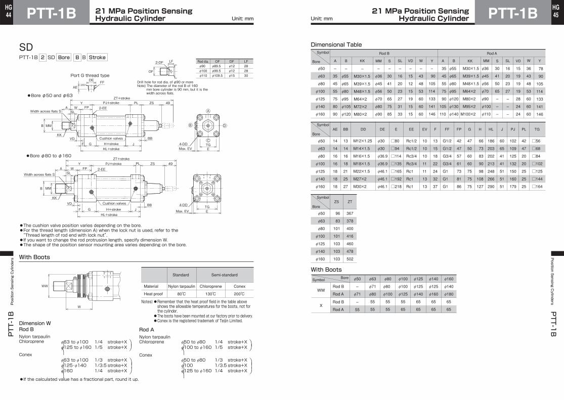
SDPTT-1B 2 SD Bore B B Stroke
Notes)●Remember that the heat proof field in the table aboveshows the allowable temperatures for the boots, not forthe cylinder.●The boots have been mounted at our factory prior to delivery.●Conex is the registered trademark of Teijin Limited.
Material
Heat proof
Standard
Nylon tarpaulin Chloroprene Conex
Semi-standard
130℃ 200℃80℃
With Boots
●If the calculated value has a fractional part, round it up.
Nylon tarpaulinChloroprene f63 to f100 1/4 stroke+X
f125 to f160 1/5 stroke+X
Conexf63 to f100 1/3 stroke+Xf125・f140 1/3.5 stroke+Xf160 1/4 stroke+X
⎞⎠
⎞⎟⎠
⎞⎠
⎞⎟
⎠
f50 to f80 1/4 stroke+Xf100 to f160 1/5 stroke+X
f50 to f80 1/3 stroke+Xf100 1/3.5 stroke+Xf125 to f160 1/4 stroke+X
⎞⎠
⎞⎟⎠
⎞⎠
⎞⎟
⎠
Nylon tarpaulinChloroprene
Conex
Rod ADimension WRod B
Port G thread typeDE
AE
OF
LF2-DF
●The cushion valve position varies depending on the bore.●For the thread length (dimension A) when the lock nut is used, refer to the“Thread length of rod end with lock nut”.●If you want to change the rod protrusion length, specify dimension W.●The shape of the position sensor mounting area varies depending on the bore.
WW
W
A
B
C
D
TGEMax. EV
●Bore φ80 to φ160
B MM
A W FPY
SL
VDF G H+stroke J
HL+stroke
PJ+stroke PL ZS 49ZT+stroke
BB
●Bore φ50 and φ63
PL ZS 49
MMB
4-DD
KKCushion valves
2-EE
FF
PJ+strokeYFPWA
SL
KKVD
ZT+stroke
F G H+stroke JBB
HL+stroke
TGEMax. EV
4-DDCushion valves
2-EE
f90f100f110
f12f12f15
f89.5f99.5f109.5
Rod dia. OF DF282830
LF
Width across flats S
Width across flats S
Drill hole for rod dia. of φ90 or moreNote) The diameter of the rod B of 160
mm bore cylinder is 90 mm, but it is thewidth across flats.
Symbol
Bore
f50
f63
f80
f100
f125
f140
f160
Dimensional Table
–
f55
f65
f80
f95
f105
f120
B
–
M30×1.5
M39×1.5
M48×1.5
M64×2
M72×2
M80×2
KK
Rod B Rod A
MM S SL VD W Y A B KK MM S SL VD W Y
–
f36
f45
f56
f70
f80
f90
–
30
41
50
65
75
85
–
16
20
23
27
31
33
–
15
12
15
19
15
15
–
43
48
53
60
60
60
–
90
105
114
133
141
146
35
45
55
75
90
105
110
f55
f65
f80
f95
f120
f130
f140
f36
f45
f56
f70
f90
f100
f110
30
41
50
65
–
–
–
16
20
23
27
–
–
–
36
43
48
53
60
60
60
78
90
105
114
133
141
146
M30×1.5
M39×1.5
M48×1.5
M64×2
M80×2
M95×2
M100×2
f50
f63
f80
f100
f125
f140
f160
13
14
16
18
21
25
27
M12×1.25
M14×1.5
M16×1.5
M18×1.5
M22×1.5
M27×2
M30×2
f30
f30
f36.9
f36.9
f46.1
f46.1
f46.1
BB DD DE E EE EV FF FP G H HL PJ PL TG
□80
□94
□114
□135
□165
□192
□218
Rc1/2
Rc1/2
Rc3/4
Rc3/4
Rc1
Rc1
Rc1
10
10
10
11
11
13
13
G1/2
G1/2
G3/4
G3/4
G1
G1
G1
42
47
57
61
73
81
86
47
50
60
60
75
75
75
66
73
83
90
98
108
127
186
203
202
213
248
266
290
102
109
125
132
150
160
179
42
47
20
20
25
25
25
□56
□68
□84
□102
□125
□144
□164
F
13
15
18
22
24
32
37
AE
14
14
16
16
18
18
18
–
35
45
55
75
80
90
A
60
65
41
41
51
51
51
J
f50
f63
f80
f100
f125
f140
f160
With Boots
ZS ZT
96
83
101
101
103
103
103
367
378
400
416
460
478
502
15
19
19
19
28
24
24
WW
X
Rod B
Rod A
Rod B
Rod A
f50 f63 f80 f100 f125 f140 f160
–
f71
f71
f80
f80
f100
f100
f125
f125
f140
f125
f160
f140
f180
–
55
55
55
55
55
55
65
65
65
65
65
65
65
Symbol
Bore
Symbol
SymbolBore
Bore
Unit: mm Unit: mm21 MPa Position Sensing
Hydraulic Cylinder21 MPa Position SensingHydraulic Cylinder
PTT-1BPTT-1B Position Sensing Cylinders
46HG
PTT-1BPosition S
ensing Cylinders
PTT-1
B47HG
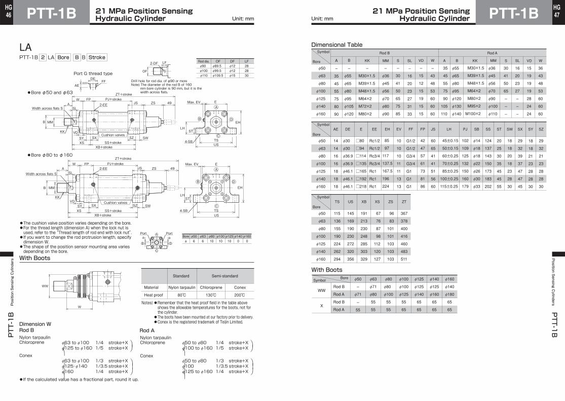
LAPTT-1B 2 LA Bore B B Stroke
With Boots
●If the calculated value has a fractional part, round it up.
Nylon tarpaulinChloroprene
Conex
Rod ADimension WRod B
Port G thread typeDE
AE
OF
LF
TSUS
STLH
EH
EMax. EV
2-DF
4-SB
FF
W FP
FPW
●The cushion valve position varies depending on the bore.●For the thread length (dimension A) when the lock nut is used, refer to the “Thread length of rod end with lock nut”.●If you want to change the rod protrusion length, specify dimension W.
●The shape of the position sensor mounting area varies depending on the bore.
Notes)●Remember that the heat proof field in the table aboveshows the allowable temperatures for the boots, not forthe cylinder.●The boots have been mounted at our factory prior to delivery.●Conex is the registered trademark of Teijin Limited.
Material
Heat proof
Standard
Nylon tarpaulin Chloroprene Conex
Semi-standard
130℃ 200℃80℃
f63 to f100 1/4 stroke+Xf125 to f160 1/5 stroke+X
f63 to f100 1/3 stroke+Xf125・f140 1/3.5 stroke+Xf160 1/4 stroke+X
⎞⎠
⎞⎟⎠
⎞⎠
⎞⎟
⎠
f50 to f80 1/4 stroke+Xf100 to f160 1/5 stroke+X
f50 to f80 1/3 stroke+Xf100 1/3.5 stroke+Xf125 to f160 1/4 stroke+X
⎞⎠
⎞⎟⎠
⎞⎠
⎞⎟
⎠
Nylon tarpaulinChloroprene
Conex
WW
W
A
B
C
DB MM
ASL
VD
PJ+strokeJS ZS 49
ZT+stroke
JS ZS 49
MMB
A
D
C
B
STLH
EH
E
B
A
C
D
a a
KKCushion valves
2-EE
PJ+strokeASL
KKVD
ZT+stroke
Cushion valves
2-EE
SWSZSXSY
SY
XS SS+strokeXB+stroke
SXXS SS+stroke
XB+stroke
SZ SWTSUS
4-SB
Max. EV
PortPortBore f50 f63 f80 f100 f125 f140 f160
a 6 6 10 10 10 0 0
Width across flats S
Width across flats S
f90f100f110
f12f12f15
f89.5f99.5f109.5
Rod dia. OF DF282830
LF
●Bore φ50 and φ63
●Bore φ80 to φ160
Drill hole for rod dia. of φ90 or moreNote) The diameter of the rod B of 160
mm bore cylinder is 90 mm, but it is thewidth across flats.
Symbol
Bore
Symbol
Bore
f50
f63
f80
f100
f125
f140
f160
f50
f63
f80
f100
f125
f140
f160
Dimensional Table
–
f55
f65
f80
f95
f105
f120
A
–
35
45
55
75
80
90
B
–
M30×1.5
M39×1.5
M48×1.5
M64×2
M72×2
M80×2
KK
Rod B Rod A
MM S SL VD W A B KK MM S SL VD W
–
f36
f45
f56
f70
f80
f90
–
30
41
50
65
75
85
–
16
20
23
27
31
33
–
15
12
15
19
15
15
–
43
48
53
60
60
60
35
45
55
75
90
105
110
f55
f65
f80
f95
f120
f130
f140
f36
f45
f56
f70
f90
f100
f110
30
41
50
65
–
–
–
16
20
23
27
–
–
–
15
19
19
19
28
24
24
36
43
48
53
60
60
60
DE E EE EH EV FF FP JS LH PJ SB SS SW
□80
□94
□114
□135
□165
□192
□218
Rc1/2
Rc1/2
Rc3/4
Rc3/4
Rc1
Rc1
Rc1
G1/2
G1/2
G3/4
G3/4
G1
G1
G1
42
47
57
61
73
81
86
60
65
41
41
51
56
60
102
109
125
132
150
160
179
f14
f18
f18
f22
f26
f30
f33
10
10
10
11
11
13
13
45±0.15
50±0.15
60±0.25
70±0.25
85±0.25
100±0.25
115±0.25
29
32
39
37
47
47
45
29
32
21
23
28
28
30
f50
f63
f80
f100
f125
f140
f160
SZSY
M30×1.5
M39×1.5
M48×1.5
M64×2
M80×2
M95×2
M100×2
85
97
117
137.5
167.5
196
224
124
137
143
150
173
183
202
18
18
20
18
23
28
30
18
18
21
23
28
28
30
AE
14
14
16
16
18
18
18
With Boots
191
213
230
248
285
303
329
XB ZSXS
67
76
87
98
112
120
127
96
83
101
101
103
103
103
SX
20
25
30
35
45
45
55
ST
145
169
190
230
272
320
356
US ZT
367
378
400
416
460
483
511
115
136
155
190
224
262
294
TS
WW
X
Rod B
Rod A
Rod B
Rod A
f50 f63 f80 f100 f125 f140 f160
–
f71
f71
f80
f80
f100
f100
f125
f125
f140
f125
f160
f140
f180
–
55
55
55
55
55
55
65
65
65
65
65
65
65
BoreSymbol
f30
f30
f36.9
f36.9
f46.1
f46.1
f46.1
Symbol
Bore
Unit: mm Unit: mm21 MPa Position Sensing
Hydraulic Cylinder21 MPa Position SensingHydraulic Cylinder

PTT-1BPTT-1B Position Sensing Cylinders
48HG
PTT-1BPosition S
ensing Cylinders
PTT-1
B49HG
FAPTT-1B 2 FA Bore B B Stroke
With Boots
Nylon tarpaulinChloroprene
Nylon tarpaulinChloroprene
Conex Conex
Rod ADimension WRod B
Port G thread typeDE
AE
OF
LF2-DF
FF
●The cushion valve position varies depending on the bore.●For the thread length (dimension A) when the lock nut is used, refer to the “Thread length of rod end with lock nut”.●If you want to change the rod protrusion length, specify dimension WA.●The shape of the position sensor mounting area varies depending on the bore.
f63 to f100 1/4 stroke+Xf125 to f160 1/5 stroke+X
f63 to f100 1/3 stroke+Xf125・f140 1/3.5 stroke+Xf160 1/4 stroke+X
⎞⎠
⎞⎟⎠
⎞⎠
⎞⎟
⎠
f50 to f80 1/4 stroke+Xf100 to f160 1/5 stroke+X
f50 to f80 1/3 stroke+Xf100 1/3.5 stroke+Xf125 to f160 1/4 stroke+X
⎞⎠
⎞⎟⎠
⎞⎠
⎞⎟
⎠●If the calculated value has a fractional part, round it up.●The gland bush for the mounting style FA differs from that for a cylinder with boots.
Notes)●Remember that the heat proof field in the table aboveshows the allowable temperatures for the boots, not forthe cylinder.●The boots have been mounted at our factory prior to delivery.●Conex is the registered trademark of Teijin Limited.
Material
Heat proof
Standard
Nylon tarpaulin Chloroprene Conex
Semi-standard
130℃ 200℃80℃
WW
WA
●Bore φ80 to φ160
●Bore φ50 and φ63
A
B
C
D
B MM
A WASL
VD
PJ+stroke PL ZS 49ZT+stroke
PL ZS 49
MMB
KKCushion valves
2-EE
PJ+strokeA
SL
KK
ZT+stroke
LL+stroke
LY+stroke
Cushion valves
2-EE
LL+strokeLY+stroke
A
B
C
DRFE
RFE
TFUF
EMax. EV
UF
TF
EMax. EV
VD
Width across flats S
Width across flats S
MF
WF YP
4-FB
4-FB
WAWF YP
MF
f90f100f110
f12f12f15
f89.5f99.5f109.5
Rod dia. OF DF282830
LF
Drill hole for rod dia. of φ90 or moreNote) The diameter of the rod B of 160
mm bore cylinder is 90 mm, but it is thewidth across flats.
f50
f63
f80
f100
f125
f140
f160
f30
f30
f36.9
f36.9
f46.1
f46.1
f46.1
DE E EE FB LLAE PJ
□80
□94
□114
□135
□165
□192
□218
Rc1/2
Rc1/2
Rc3/4
Rc3/4
Rc1
Rc1
Rc1
f14
f18
f18
f22
f26
f30
f33
G1/2
G1/2
G3/4
G3/4
G1
G1
G1
–
212
208
222
261
275
299
14
14
16
16
18
18
18
102
109
125
132
150
160
179
–
24
24
31
37
41
46
f50
f63
f80
f100
f125
f140
f160
–
f55
f65
f80
f95
f105
f120
–
35
45
55
75
80
90
B
–
M30×1.5
M39×1.5
M48×1.5
M64×2
M72×2
M80×2
KK MM S SL VD WA A B KK MM S SL VD WA
–
f36
f45
f56
f70
f80
f90
–
30
41
50
65
75
85
–
16
20
23
27
31
33
–
6
6
6
6
6
6
–
34
42
44
47
51
51
35
45
55
75
90
105
110
f55
f65
f80
f95
f120
f130
f140
f36
f45
f56
f70
f90
f100
f110
30
41
50
65
–
–
–
16
20
23
27
–
–
–
8
10
13
10
15
15
15
29
34
42
44
47
51
51
M30×1.5
M39×1.5
M48×1.5
M64×2
M80×2
M95×2
M100×2
FE
92
105
140
165
195
215
245
–
98
125
150
175
195
225
FE
Rod B Rod A Rod B Rod A Rod B Rod A
FWFW
49
58
66
75
84
92
97
A
173
188
184
191
224
234
253
f50
f63
f80
f100
f125
f140
f160
YP
29
32
39
39
49
49
49
With Boots
WW
X
f50 f63 f80 f100 f125 f140 f160
–
f71
f71
f80
f80
f100
f100
f125
f125
f140
f125
f160
f140
f180
–
55
55
55
55
55
55
65
65
65
65
65
65
65
BoreSymbol
–
58
66
75
84
92
97
193
212
208
222
261
275
299
LYLY MFMF
20
24
24
31
37
41
46
PL
42
47
20
20
25
25
25
TF UF
115
132
155
190
224
250
285
145
165
190
230
272
300
345
EV
10
10
10
11
11
13
13
FF
ZS
96
83
101
101
103
103
103
ZT
367
378
400
416
460
478
502
R
58
65
87
109
130
145
170
Symbol
Bore
Symbol
Bore
Symbol
Bore
Dimensional TableRod B Rod A
Rod B
Rod A
Rod B
Rod A
Unit: mm Unit: mm21 MPa Position Sensing
Hydraulic Cylinder21 MPa Position SensingHydraulic Cylinder
PTT-1BPTT-1B Position Sensing Cylinders
50HG
PTT-1BPosition S
ensing Cylinders
PTT-1
B51HG
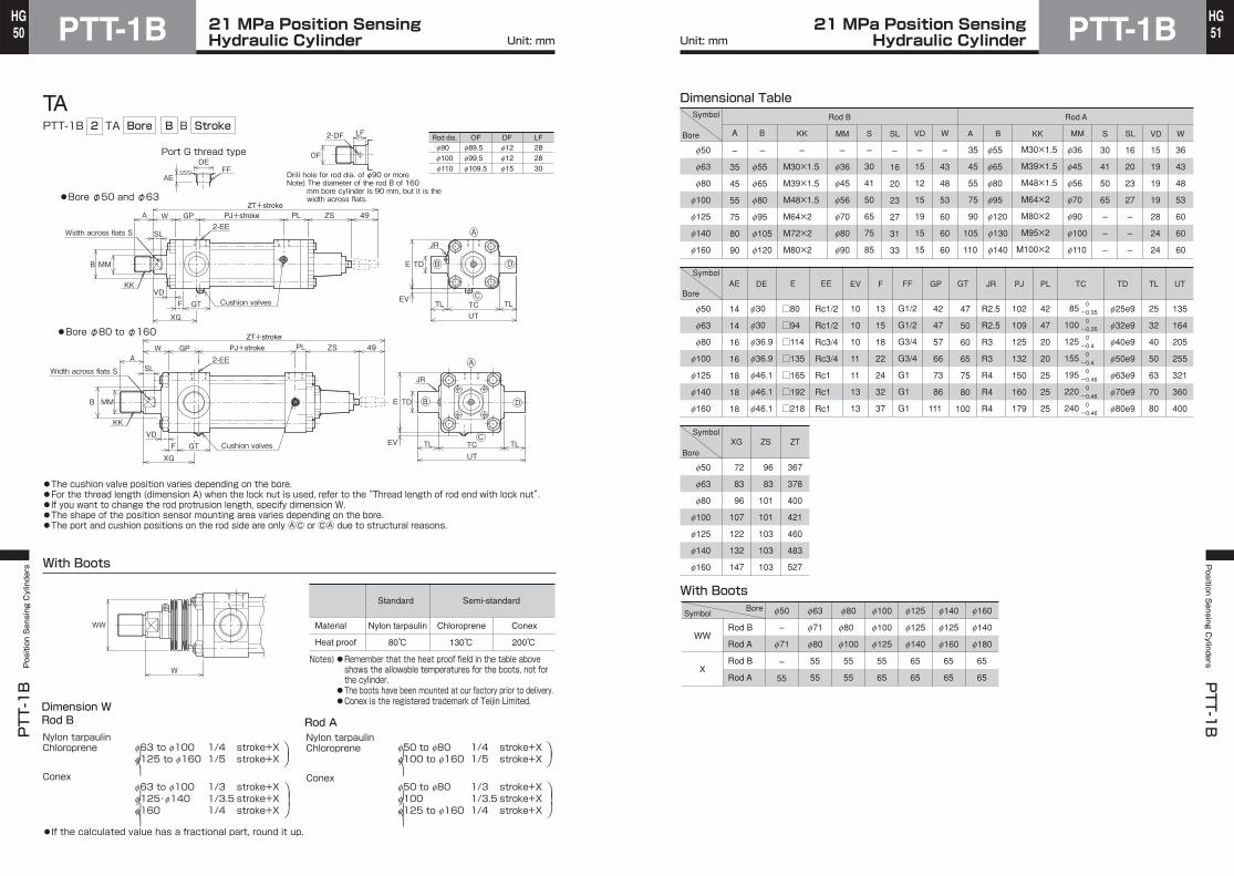
TAPTT-1B 2 TA Bore B B Stroke
With Boots
●If the calculated value has a fractional part, round it up.
Nylon tarpaulinChloroprene
Conex
Port G thread typeDE
AE
OF
LF2-DF
FF
●The cushion valve position varies depending on the bore.●For the thread length (dimension A) when the lock nut is used, refer to the “Thread length of rod end with lock nut”.●If you want to change the rod protrusion length, specify dimension W.●The shape of the position sensor mounting area varies depending on the bore.●The port and cushion positions on the rod side are only ⒶⒸ or ⒸⒶ due to structural reasons.
Dimension WRod B
Nylon tarpaulinChloroprene
Conex
Rod A
f63 to f100 1/4 stroke+Xf125 to f160 1/5 stroke+X
f63 to f100 1/3 stroke+Xf125・f140 1/3.5 stroke+Xf160 1/4 stroke+X
⎞⎠
⎞⎟⎠
⎞⎠
⎞⎟
⎠
f50 to f80 1/4 stroke+Xf100 to f160 1/5 stroke+X
f50 to f80 1/3 stroke+Xf100 1/3.5 stroke+Xf125 to f160 1/4 stroke+X
⎞⎠
⎞⎟⎠
⎞⎠
⎞⎟
⎠
Notes)●Remember that the heat proof field in the table aboveshows the allowable temperatures for the boots, not forthe cylinder.●The boots have been mounted at our factory prior to delivery.●Conex is the registered trademark of Teijin Limited.
Material
Heat proof
Standard
Nylon tarpaulin Chloroprene Conex
Semi-standard
130℃ 200℃80℃
WW
W
B MM
A W GP
SL
VDF GT
PJ+stroke PL ZS 49ZT+stroke
PL ZS 49
MMB
KK
Cushion valves
2-EE
PJ+strokeGPWASL
KKVD
ZT+stroke
F GT Cushion valves
2-EE
Width across flats S
Width across flats S
A
B
C
D
TC TLTLUT
TDE
EV
TDE
EV
B
C
D
A
XG
TCTL TLUTXG
JR
JR
●Bore φ80 to φ160
●Bore φ50 and φ63
Drill hole for rod dia. of φ90 or moreNote) The diameter of the rod B of 160
mm bore cylinder is 90 mm, but it is thewidth across flats.
f90f100f110
f12f12f15
f89.5f99.5f109.5
Rod dia. OF DF282830
LF
f50
f63
f80
f100
f125
f140
f160
f30
f30
f36.9
f36.9
f46.1
f46.1
f46.1
DE E EE EV GP GT JRAE PJ TC
□80
□94
□114
□135
□165
□192
□218
Rc1/2
Rc1/2
Rc3/4
Rc3/4
Rc1
Rc1
Rc1
10
10
10
11
11
13
13
42
47
57
66
73
86
111
47
50
60
65
75
80
100
R2.5
R2.5
R3
R3
R4
R4
R4
14
14
16
16
18
18
18
102
109
125
132
150
160
179
85
100
125
155
195
220
240
0-0.35 0-0.35 0-0.4 0-0.4 0-0.46 0-0.46 0-0.46
f50
f63
f80
f100
f125
f140
f160
Dimensional Table
–
f55
f65
f80
f95
f105
f120
A
–
35
45
55
75
80
90
B
–
M30×1.5
M39×1.5
M48×1.5
M64×2
M72×2
M80×2
KK
Rod B Rod A
MM S SL VD W A B KK MM S SL VD W
–
f36
f45
f56
f70
f80
f90
–
30
41
50
65
75
85
–
16
20
23
27
31
33
–
15
12
15
19
15
15
–
43
48
53
60
60
60
35
45
55
75
90
105
110
f55
f65
f80
f95
f120
f130
f140
f36
f45
f56
f70
f90
f100
f110
30
41
50
65
–
–
–
16
20
23
27
–
–
–
15
19
19
19
28
24
24
36
43
48
53
60
60
60
M30×1.5
M39×1.5
M48×1.5
M64×2
M80×2
M95×2
M100×2
FF
G1/2
G1/2
G3/4
G3/4
G1
G1
G1
With Boots
f50
f63
f80
f100
f125
f140
f160
PL
42
47
20
20
25
25
25
ZS ZT
96
83
101
101
103
103
103
367
378
400
421
460
483
527
XG
72
83
96
107
122
132
147
WW
X
f50 f63 f80 f100 f125 f140 f160
–
f71
f71
f80
f80
f100
f100
f125
f125
f140
f125
f160
f140
f180
–
55
55
55
55
55
55
65
65
65
65
65
65
65
BoreSymbol
F
13
15
18
22
24
32
37
TL
25
32
40
50
63
70
80
TD
f25e9
f32e9
f40e9
f50e9
f63e9
f70e9
f80e9
UT
135
164
205
255
321
360
400
Symbol
Bore
Symbol
Bore
Symbol
Bore
Rod B
Rod A
Rod B
Rod A
Unit: mm Unit: mm21 MPa Position Sensing
Hydraulic Cylinder21 MPa Position SensingHydraulic Cylinder
PTT-1BPTT-1B Position Sensing Cylinders
52HG
PTT-1BPosition S
ensing Cylinders
PTT-1
B53HG
TCPTT-1B 2 TC Bore B B Stroke
With Boots
●If the calculated value has a fractional part, round it up.
Nylon tarpaulinChloroprene
Nylon tarpaulinChloroprene
Conex Conex
Rod ADimension WRod B
Port G thread typeDE
AE
OF
LF2-DF
●The cushion valve position varies depending on the bore.●For the thread length (dimension A) when the lock nut is used, refer to the“Thread length of rod end with lock nut”.●If you want to change the rod protrusion length, specify dimension W.●The shape of the position sensor mounting area varies depending on the bore.●If dimension PH is small, pay attention to the cushion valve position.
f63 to f100 1/4 stroke+Xf125 to f160 1/5 stroke+X
f63 to f100 1/3 stroke+Xf125・f140 1/3.5 stroke+Xf160 1/4 stroke+X
⎞⎠
⎞⎟⎠
⎞⎠
⎞⎟
⎠
f50 to f80 1/4 stroke+Xf100 to f160 1/5 stroke+X
f50 to f80 1/3 stroke+Xf100 1/3.5 stroke+Xf125 to f160 1/4 stroke+X
⎞⎠
⎞⎟⎠
⎞⎠
⎞⎟
⎠
Notes)●Remember that the heat proof field in the table aboveshows the allowable temperatures for the boots, not forthe cylinder.●The boots have been mounted at our factory prior to delivery.●Conex is the registered trademark of Teijin Limited.
Material
Heat proof
Standard
Nylon tarpaulin Chloroprene Conex
Semi-standard
130℃ 200℃80℃
WW
W
A
B
C
D
B MM
A W FP
SL
VD
PJ+stroke PL ZS 49ZT+stroke
PL ZS 49
MMB
KK
Cushion valves
2-EE
FF
PJ+strokeFPWASL
KKVD
ZT+stroke
Cushion valves
2-EE
Width across flats S
Width across flats S
A
B
C
D
BDTMTL TLUM
EMax. EV
TDUW
JR
TDUW
XV+1/2 stroke (=PH)
TMTL TL
UM
EMax. EV
BD
XV+1/2 stroke (=PH)
JR
●Bore φ80 to φ160
●Bore φ50 and φ63
Drill hole for rod dia. of φ90 or moreNote) The diameter of the rod B of 160
mm bore cylinder is 90 mm, but it is thewidth across flats.
f90f100f110
f12f12f15
f89.5f99.5f109.5
Rod dia. OF DF282830
LF
f50
f63
f80
f100
f125
f140
f160
f30
f30
f36.9
f36.9
f46.1
f46.1
f46.1
DE E EE EV FP JRAE PJMin.
dimension PH
□80
□94
□114
□135
□165
□192
□218
Rc1/2
Rc1/2
Rc3/4
Rc3/4
Rc1
Rc1
Rc1
10
10
10
11
11
13
13
42
47
57
61
73
81
86
R2.5
R2.5
R3
R3
R4
R4
R4
14
14
16
16
18
18
18
102
109
125
132
150
160
179
f50
f63
f80
f100
f125
f140
f160
–
f55
f65
f80
f95
f105
f120
A
–
35
45
55
75
80
90
B
–
M30×1.5
M39×1.5
M48×1.5
M64×2
M72×2
M80×2
KK MM S SL VD W A B KK MM S SL VD W
–
f36
f45
f56
f70
f80
f90
–
30
41
50
65
75
85
–
16
20
23
27
31
33
–
15
12
15
19
15
15
–
43
48
53
60
60
60
35
45
55
75
90
105
110
f55
f65
f80
f95
f120
f130
f140
f36
f45
f56
f70
f90
f100
f110
30
41
50
65
–
–
–
16
20
23
27
–
–
–
15
19
19
19
28
24
24
36
43
48
53
60
60
60
M30×1.5
M39×1.5
M48×1.5
M64×2
M80×2
M95×2
M100×2
FF
G1/2
G1/2
G3/4
G3/4
G1
G1
G1
With Boots
f50
f63
f80
f100
f125
f140
f160
PL
42
47
20
20
25
25
25
UW XV
80
94
114
146
185
210
230
129
144.5
167.5
180
208
221
235.5
UM
135
164
205
255
321
360
400
WW
X
f50 f63 f80 f100 f125 f140 f160
–
f71
f71
f80
f80
f100
f100
f125
f125
f140
f125
f160
f140
f180
–
55
55
55
55
55
55
65
65
65
65
65
65
65
BoreSymbol
TL
25
32
40
50
63
70
80
TD
f25e9
f32e9
f40e9
f50e9
f63e9
f70e9
f80e9
BD
33
43
53
63
78
88
98
112.5
129.5
152.5
166.5
198
211
221
TM
85
100
125
155
195
220
240
0-0.35 0-0.35 0-0.4 0-0.4 0-0.46 0-0.46 0-0.46
ZS
96
83
101
101
103
103
103
ZT
367
378
400
416
460
478
502
Dimensional TableSymbol
Bore
Symbol
Bore
Symbol
Bore
Rod B Rod A
Rod B
Rod A
Rod B
Rod A
Unit: mm Unit: mm21 MPa Position Sensing
Hydraulic Cylinder21 MPa Position SensingHydraulic Cylinder
PTT-1BPTT-1B Position Sensing Cylinders
54HG
PTT-1BPosition S
ensing Cylinders
PTT-1
B55HG
Rod End Attachment●Rod eye (T-end)
●Rod clevis (Y-end) with pin
●Delivery of rod end attachment (T-end or Y-end)
●If the rod A is used, change the rod end thread diameter to that of the rod B.
●If the rod A is used, change the rod end thread diameter to that of the rod B.
①When the lock nut and rod end attachment are additionally orderedThe rod end attachment and lock nut are temporarily assembled to the piston rod for delivery. Since the lock nut is not tightened, tighten it after adjusting the position of the rod end attachment.No hex. screw is supplied.
②When only the rod end attachment is additionally ordered (without lock nut)The rod end attachment is tightened to the piston rod, a drill hole is made on the piston rod and it is secured with the hex. screw for delivery.
If the drilled hole is unnecessary, give us such instructions.
Hex. screw
KK
CK
EM
ED
AV
JRA
45°
CRLE
CE
Retainer
Retainer mounting bolt
KK
Hex. screw
CK
BL
ED
RAJ
CL CM
CW
CV
CW
LECECR
45°
Rod endattachment
Rod endattachment
Hex. screw is not supplied.Tapped hole only.
Drilled
Hex. screw (full dog point)
Piston rod
Piston rodLock nut
Symbol
Bore
f50
f63
f80
f100
f125
f140
f160
Part number
RTH-24-3-H
RTH-30-2-H
RTH-39-2-H
RTH-48-2-H
RTH-64-3-H
RTH-72-3-H
RTH-80-3-H
AV
35
40
53
62
80
87
96
CE
80
95
110
135
160
180
195
CK
f25H10
f32H10
f40H10
f50H10
f63H10
f70H10
f80H10
CR
30
35
40
50
63
70
80
ED
f55
f70
f80
f98
f118
f138
f158
EM
32
40
50
63
80
90
100
J
15
16
15
20
30
35
40
KK
M24×1.5
M30×1.5
M39×1.5
M48×1.5
M64×2
M72×2
M80×2
LE
34
42
52
65
75
82
94
RA
110
130
150
185
223
250
275
H10f8
H10f8
H10f8
H10f8
Dimensional Table: Rod eye (T-end)
Dimensional Table: Rod clevis (Y-end) with pin
Rod B
f50
f63
f80
f100
f125
f140
f160
RYH-24-3-H
RYH-30-1-H
RYH-39-2-H
RYH-48-2-H
RYH-64-3-H
RYH-72-3-H
RYH-80-3-H
77
93
117
143
183
203
223
80
95
110
135
160
180
195
f25
f32
f40
f50
f63
f70
f80
64
80
100
126
160
180
200
32
40
50
63
80
90
100
30
35
40
50
63
70
80
8
8
12
12
18
18
18
16
20
25
31.5
40
45
50
60
70
80
100
120
140
160
15
16
15
20
30
35
40
M24×1.5
M30×1.5
M39×1.5
M48×1.5
M64×2
M72×2
M80×2
34
42
52
65
75
82
94
110
130
150
185
223
250
275
Part number BL CE CK CL CM CR CV CW ED J KK LE RA
H10f8
H10f8
H10f8
-0.1-0.4
-0.1-0.4
-0.1-0.6
-0.1-0.6
-0.1-0.6
-0.1-0.4
-0.1-0.4
+0.4+0.1
+0.4+0.1
+0.6+0.1
+0.6+0.1
+0.6+0.1
+0.4+0.1
+0.4+0.1
Symbol
Bore
Rod B
●The rod end attachments are dedicated to the rod B. To use them for the rod A, give instructions to change the rod A end thread diameter to that of the rod B.When the rod end attachment and the lock nut are used for a cylinder with the rod A, give instructions to change the rod end thread diameter to the thread diameter of the rod B and change dimension A to that for the use of lock nut.
Note)
Unit: mm Unit: mm21 MPa Position Sensing
Hydraulic Cylinder21 MPa Position SensingHydraulic Cylinder
PTT-1BPTT-1B Position Sensing Cylinders
56HG
PTT-1BPosition S
ensing Cylinders
PTT-1
B57HG
●Lock nut ●Thread length of rod end with lock nut
●Parallel pin
●Retainer
C D E
BL Standard type
CK
2-L
F
G
H
I
J
K
The standard fitting length of the rod end attachment and piston rod is about 80% of the thread diameter. Therefore, if you order a cylinder with a lock nut, dimension A is longer.
H B
C
dLock nut
Rod endattachment
A
KK
Dimensional Table: Dimension A when lock nut is used (long thread)
Dimensional Table: Lock nut
Dimensional Table: Retainer
Dimensional Table: Parallel pin
Symbol
Bore
f50
f63
f80
f100
f125
f140
f160
A
50
60
80
95
125
140
155
M24×1.5
M30×1.5
M39×1.5
M48×1.5
M64×2
M72×2
M80×2
KK
Rod B Rod A
A KK
60
80
95
125
155
185
190
M30×1.5
M39×1.5
M48×1.5
M64×2
M80×2
M95×2
M100×2
f50
f63
f80
f100
f125
f140
f160
Part number B
Rod B Rod A
C d H Part number B C d H
LNH-24F-1-H
LNH-30F-1-H
LNH-39F-1-H
LNH-48F-1-H
LNH-64F-1-H
LNH-72F-1-H
LNH-80F-1-H
LNH-30F-1-H
LNH-39F-1-H
LNH-48F-1-H
LNH-64F-1-H
LNH-80F-1-H
LNH-95F-1-H
LNH-100F-1-H
36
46
60
75
95
105
115
M24×1.5
M30×1.5
M39×1.5
M48×1.5
M64×2
M72×2
M80×2
20
25
32
38
51
58
64
46
60
75
95
115
135
145
53.1
69.3
86.6
109.7
132.8
155.9
167.4
M30×1.5
M39×1.5
M48×1.5
M64×2
M80×2
M95×2
M100×2
25
32
38
51
64
76
80
41.6
53.1
69.3
86.6
109.7
121.2
132.8
f50
f63
f80
f100
f125
f140
f160
77
93
117
143
183
203
223
5
5
7
7
10
10
10
BL
f25
f32
f40
f50
f63
f70
f80
3
3
5
5
8
8
8
C CK D E
3.5
4
5
5
8
8
8
●The tolerance of CK is f8.
f50
f63
f80
f100
f125
f140
f160
32
32
50
65
75
75
75
18
18
30
40
48
48
48
F
8
8
10
12
17
17
17
7
7
8
10
13
13
13
G H I J K LRetainermountingbolt size
15
15
18
22
30
30
30
4.5
4.5
6
6
9
9
9
f7
f7
f10
f12
f14
f14
f14
M6
M6
M8
M10
M12
M12
M12
Symbol
Bore
Symbol
Bore
Symbol
Bore
Unit: mm Unit: mm21 MPa Position Sensing
Hydraulic Cylinder21 MPa Position SensingHydraulic Cylinder


![PTT Multicasting Scheme [호환 모드] · 2 New PTT Group Add by Mouse right button click 3PTTGrouppg Name Setting 4 PTT Group Number Setting 5 PTT Server Setting 6 PTT Group Session](https://img.pdfslide.us/doc/110x75/5f727989ade5745a8a06acb0/ptt-multicasting-scheme-eeoe-2-new-ptt-group-add-by-mouse-right-button.jpg)