Embed Size (px)
Citation preview
HEA
VY
DU
TY
CY
LIN
DR
ICA
LLO
CK
S–
LEV
ER
S
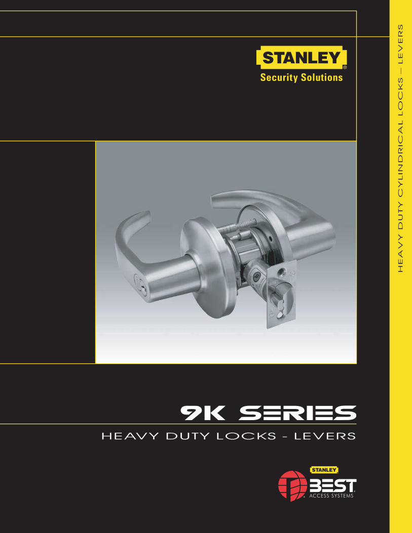
HEAVY DUTY LOCKS - LEVERS
2 H E AV Y D U T Y L
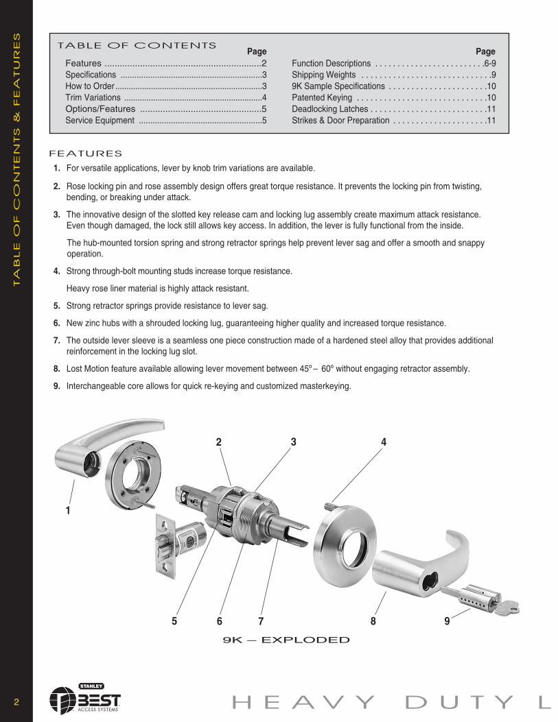
TABLE OF CONTENTS
Features ..............................................................2Specifications ..............................................................3How to Order ..................................................................3Trim Variations ..............................................................4Options/Features ................................................5Service Equipment ......................................................5
Function Descriptions . . . . . . . . . . . . . . . . . . . . . . . . .6-9Shipping Weights . . . . . . . . . . . . . . . . . . . . . . . . . . . . .99K Sample Specifications . . . . . . . . . . . . . . . . . . . . . .10Patented Keying . . . . . . . . . . . . . . . . . . . . . . . . . . . . .10Deadlocking Latches . . . . . . . . . . . . . . . . . . . . . . . . . .11Strikes & Door Preparation . . . . . . . . . . . . . . . . . . . . .11
FEATURES
Page Page
TA
BLE
OF
CO
NTEN
TS
&FEA
TU
RES
9K – EXPLODED
1. For versatile applications, lever by knob trim variations are available.
2. Rose locking pin and rose assembly design offers great torque resistance. It prevents the locking pin from twisting,bending, or breaking under attack.
3. The innovative design of the slotted key release cam and locking lug assembly create maximum attack resistance.Even though damaged, the lock still allows key access. In addition, the lever is fully functional from the inside.
The hub-mounted torsion spring and strong retractor springs help prevent lever sag and offer a smooth and snappyoperation.
4. Strong through-bolt mounting studs increase torque resistance.
Heavy rose liner material is highly attack resistant.
5. Strong retractor springs provide resistance to lever sag.
6. New zinc hubs with a shrouded locking lug, guaranteeing higher quality and increased torque resistance.
7. The outside lever sleeve is a seamless one piece construction made of a hardened steel alloy that provides additionalreinforcement in the locking lug slot.
8. Lost Motion feature available allowing lever movement between 45º – 60º without engaging retractor assembly.
9. Interchangeable core allows for quick re-keying and customized masterkeying.
1
2 3 4
5 6 7 8 9
14– curvedreturn
15– contourangle return
16– curvedno return
O C K - L E V E R S 3
SP
EC
IFIC
ATIO
NS
* Handles are made from a zinc alloy, and have been plated to be equivalent in appearance to the finishes listed.For information on 9K non IC products please refer to Best’s non-IC keying products brochure.
pages 4-5 page 11pages 6-9
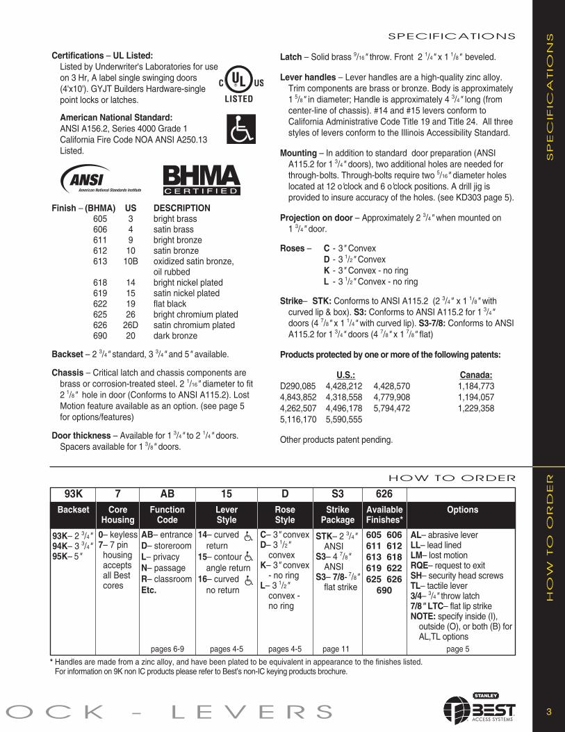
AL– abrasive leverLL– lead linedLM– lost motionRQE– request to exitSH– security head screwsTL– tactile lever3/4– 3/4" throw latch7/8" LTC– flat lip strikeNOTE: specify inside (I),
outside (O), or both (B) forAL,TL options
Options
605 606611 612613 618619 622625 626690
93K 7 AB 15 D S3 626Backset Core
HousingFunctionCode
LeverStyle
RoseStyle
C– 3" convexD– 3 1/2"
convexK– 3" convex
- no ringL– 3 1/2"
convex -no ring
StrikePackage
STK– 2 3/4"ANSI
S3– 4 7/8"ANSI
S3– 7/8- 7/8"flat strike
AvailableFinishes*
HOW TO ORDER
SPECIFICATIONS
HO
WTO
OR
DER
pages 4-5 page 5
93K– 2 3/4"94K– 3 3/4"95K– 5"
0– keyless7– 7 pinhousingacceptsall Bestcores
AB– entranceD– storeroomL– privacyN– passageR– classroomEtc.
Latch – Solid brass 9/16" throw. Front 2 1/4" x 1 1/8" beveled.
Lever handles – Lever handles are a high-quality zinc alloy.Trim components are brass or bronze. Body is approximately1 5/8" in diameter; Handle is approximately 4 3/4" long (fromcenter-line of chassis). #14 and #15 levers conform toCalifornia Administrative Code Title 19 and Title 24. All threestyles of levers conform to the Illinois Accessibility Standard.
Mounting – In addition to standard door preparation (ANSIA115.2 for 1 3/4" doors), two additional holes are needed forthrough-bolts. Through-bolts require two 5/16" diameter holeslocated at 12 o'clock and 6 o'clock positions. A drill jig isprovided to insure accuracy of the holes. (see KD303 page 5).
Projection on door – Approximately 2 3/4" when mounted on1 3/4" door.
Roses – C - 3" ConvexD - 3 1/2" ConvexK - 3" Convex - no ringL - 3 1/2" Convex - no ring
Strike– STK: Conforms to ANSI A115.2 (2 3/4" x 1 1/8" withcurved lip & box). S3: Conforms to ANSI A115.2 for 1 3/4"doors (4 7/8" x 1 1/4" with curved lip). S3-7/8: Conforms to ANSIA115.2 for 1 3/4" doors (4 7/8" x 1 7/8" flat)
Products protected by one or more of the following patents:
U.S.: Canada:D290,085 4,428,212 4,428,570 1,184,7734,843,852 4,318,558 4,779,908 1,194,0574,262,507 4,496,178 5,794,472 1,229,3585,116,170 5,590,555
Other products patent pending.
Certifications – UL Listed:Listed by Underwriter's Laboratories for useon 3 Hr, A label single swinging doors(4'x10'). GYJT Builders Hardware-singlepoint locks or latches.
American National Standard:ANSI A156.2, Series 4000 Grade 1California Fire Code NOA ANSI A250.13Listed.
Finish – (BHMA) US DESCRIPTION605 3 bright brass606 4 satin brass611 9 bright bronze612 10 satin bronze613 10B oxidized satin bronze,
oil rubbed618 14 bright nickel plated619 15 satin nickel plated622 19 flat black625 26 bright chromium plated626 26D satin chromium plated690 20 dark bronze
Backset – 2 3/4" standard, 3 3/4" and 5" available.
Chassis – Critical latch and chassis components arebrass or corrosion-treated steel. 2 1/16" diameter to fit2 1/8" hole in door (Conforms to ANSI A115.2). LostMotion feature available as an option. (see page 5for options/features)
Door thickness – Available for 1 3/4" to 2 1/4" doors.Spacers available for 1 3/8" doors.
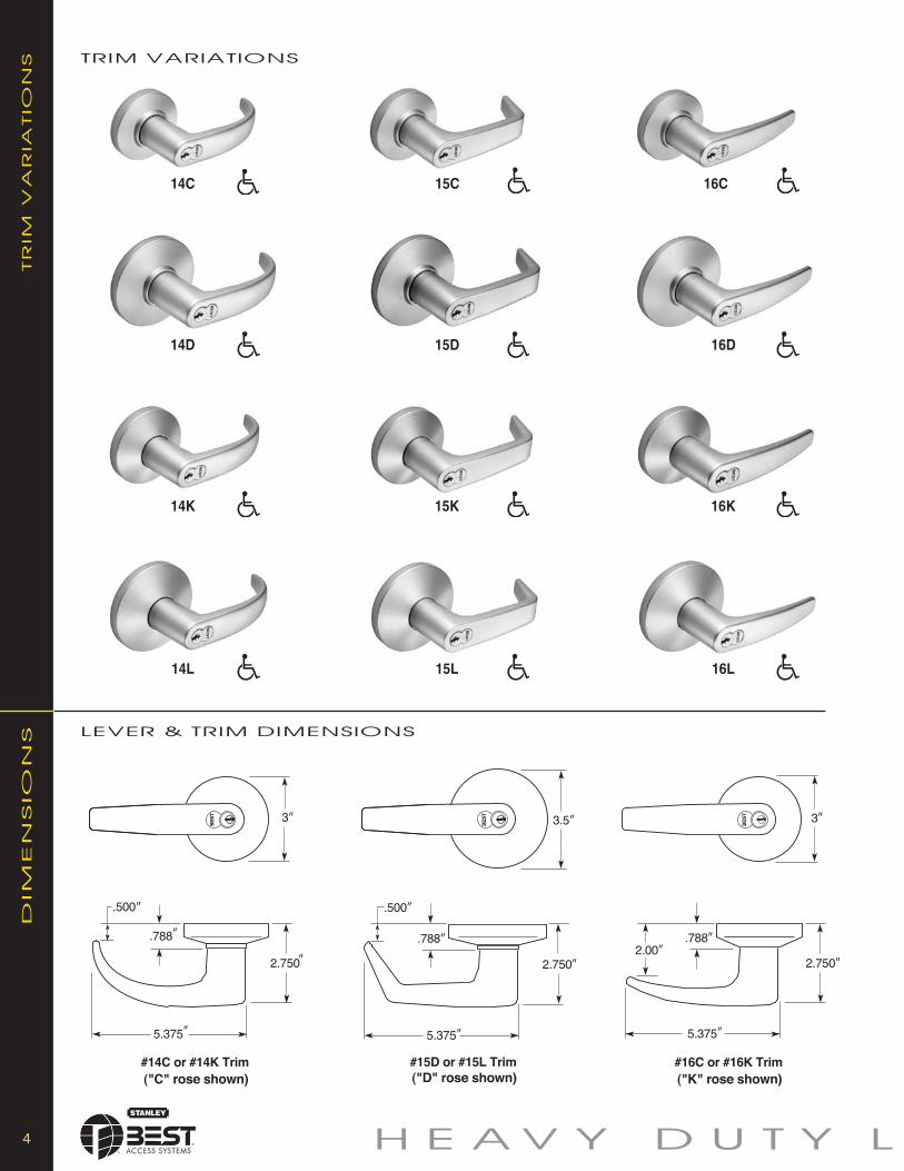
16C
16D
16K
16L
15C
15D
15K
15L
14D
14K
14L
4 H E AV Y D U T Y L
TR
IMV
AR
IATIO
NS
DIM
EN
SIO
NS
TRIM VARIATIONS
LEVER & TRIM DIMENSIONS
14C
O C K - L E V E R S 5
OP
TIO
NS/FEA
TU
RESOPTIONS/FEATURES
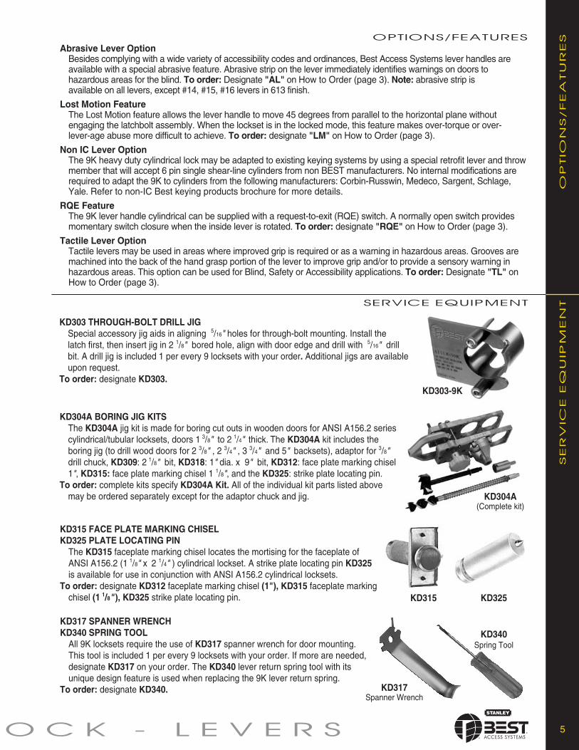
Abrasive Lever OptionBesides complying with a wide variety of accessibility codes and ordinances, Best Access Systems lever handles areavailable with a special abrasive feature. Abrasive strip on the lever immediately identifies warnings on doors tohazardous areas for the blind. To order: Designate "AL" on How to Order (page 3). Note: abrasive strip isavailable on all levers, except #14, #15, #16 levers in 613 finish.
Lost Motion FeatureThe Lost Motion feature allows the lever handle to move 45 degrees from parallel to the horizontal plane withoutengaging the latchbolt assembly. When the lockset is in the locked mode, this feature makes over-torque or over-lever-age abuse more difficult to achieve. To order: designate "LM" on How to Order (page 3).
Non IC Lever OptionThe 9K heavy duty cylindrical lock may be adapted to existing keying systems by using a special retrofit lever and throwmember that will accept 6 pin single shear-line cylinders from non BEST manufacturers. No internal modifications arerequired to adapt the 9K to cylinders from the following manufacturers: Corbin-Russwin, Medeco, Sargent, Schlage,Yale. Refer to non-IC Best keying products brochure for more details.
RQE FeatureThe 9K lever handle cylindrical can be supplied with a request-to-exit (RQE) switch. A normally open switch providesmomentary switch closure when the inside lever is rotated. To order: designate "RQE" on How to Order (page 3).
Tactile Lever OptionTactile levers may be used in areas where improved grip is required or as a warning in hazardous areas. Grooves aremachined into the back of the hand grasp portion of the lever to improve grip and/or to provide a sensory warning inhazardous areas. This option can be used for Blind, Safety or Accessibility applications. To order: Designate "TL" onHow to Order (page 3).
KD315 FACE PLATE MARKING CHISELKD325 PLATE LOCATING PIN
The KD315 faceplate marking chisel locates the mortising for the faceplate ofANSI A156.2 (1 1/8" x 2 1/4" ) cylindrical lockset. A strike plate locating pin KD325is available for use in conjunction with ANSI A156.2 cylindrical locksets.
To order: designate KD312 faceplate marking chisel (1"), KD315 faceplate markingchisel (1 1/8" ), KD325 strike plate locating pin.
KD317 SPANNER WRENCHKD340 SPRING TOOL
All 9K locksets require the use of KD317 spanner wrench for door mounting.This tool is included 1 per every 9 locksets with your order. If more are needed,designate KD317 on your order. The KD340 lever return spring tool with itsunique design feature is used when replacing the 9K lever return spring.
To order: designate KD340.
SER
VIC
EEQ
UIP
MEN
TSERVICE EQUIPMENT
KD304A BORING JIG KITSThe KD304A jig kit is made for boring cut outs in wooden doors for ANSI A156.2 seriescylindrical/tubular locksets, doors 1 3/8" to 2 1/4" thick. The KD304A kit includes theboring jig (to drill wood doors for 2 3/8" , 2 3/4" , 3 3/4" and 5" backsets), adaptor for 3/8"drill chuck, KD309: 2 1/8" bit, KD318: 1" dia. x 9" bit, KD312: face plate marking chisel1", KD315: face plate marking chisel 1 1/8", and the KD325: strike plate locating pin.
To order: complete kits specify KD304A Kit. All of the individual kit parts listed abovemay be ordered separately except for the adaptor chuck and jig.
KD303 THROUGH-BOLT DRILL JIGSpecial accessory jig aids in aligning 5/16" holes for through-bolt mounting. Install thelatch first, then insert jig in 2 1/8" bored hole, align with door edge and drill with 5/16" drillbit. A drill jig is included 1 per every 9 locksets with your order. Additional jigs are availableupon request.
To order: designate KD303.KD303-9K
KD315 KD325
KD340Spring Tool
KD317Spanner Wrench
KD304A(Complete kit)
6 H E AV Y D U T Y L
FU
NC
TIO
NS FUNCTIONS
• Rotating the inside lever,• Turning the key in the
outside lever-only when theinside push button is out,
• Removing the core with acontrol key and using aspecial emergency key
Pushing the inside button projects an “occupied” indicator in the outside lever and blocks all operating keys.
• Rotating the inside lever,• Rotating the outside
lever—only when the insidepush button is out,
• Turning the key in theoutside lever
Corridor
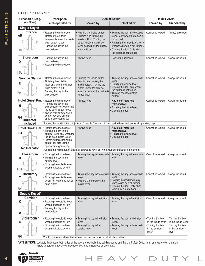
*ATTENTION: Locksets that secure both sides of the door are controlled by building codes and the Life Safety Code. In an emergency exit situation,failure to quickly unlock the inside lever could be hazardous or even fatal.
G
F91
Always unlocked• Pushing the inside button,• Pushing and turning the
inside button. Turning thebutton keeps the outsidelever locked until the buttonis turned back
• Turning the key in the outsidelever, (only when the button isnot turned)
• Rotating the inside lever, (onlywhen the button is not turned).
• Closing the door (only whenthe button is not turned)
Cannot be locked
Pushing the inside button blocks all operating keys, but no “occupied” indicator is projected.
Turning the key in either the inside or the outside, locks or unlocks both sides.
Double Keyed*
• Turning the key in theoutside lever,
• Rotating the inside lever
• Rotating the inside lever,• Rotating the outside
lever-only when the insidepush button is out.
• Turning the key in theoutside lever
• Rotating the inside lever,• Turning the key in the
outside lever-only when theinside push button is out,
• Removing the core with acontrol key and using aspecial emergency key
• Rotating the inside lever,• Turning the key in the
outside lever,• Rotating the outside lever
when not locked by key
• Rotating the inside lever,• Rotating the outside lever
when not locked by key orpush button
• Rotating the inside lever,• Rotating the outside lever
when not locked by key,• Turning the key in the
outside lever
• Rotating the outside leverwhen not locked by key,
• Rotating the inside leverwhen not locked by key
Always fixed
• Pushing the inside button,• Pushing and turning the
inside button. Turning thebutton keeps the outsidelever locked until the button isturned back
Turning the key in the outsidelever
• Turning the key in the outsidelever,
• Pushing the button on theinside lever
Turning the key in the insidelever
• Turning the key in the insidelever,
• Turning the key in theoutside lever
Cannot be unlocked
• Turning the key in the outsidelever,
• Rotating the inside lever,• Closing the door-only when
the button is not turned,• Turning back the slotted
button
Key block feature isreleased by:
• Rotating the inside lever,• Closing the door
• Turning the key in the outsidelever,
• Rotating the inside lever (onlywhen locked by push button),
• Closing the door (only whenlocked by push button)
EntranceAB
F109
StoreroomD
F86
Service Station
E
F92
Hotel Guest Rm.
H
F93
Hotel Guest Rm.
HJ
ClassroomR
F84
T
F90
Dormitory
C
F88
Storeroom *
Always unlockedCannot be locked
Always unlockedCannot be locked
Always fixed Always unlockedCannot be locked
• Turning the keyin the inside lever,
• Turning the keyin the outsidelever
Always fixed Key block feature isreleased by:
• Rotating the inside lever,• Closing the door
Always unlockedCannot be locked
Turning the key in the outsidelever
Always unlockedCannot be locked
Always unlockedCannot be locked
Always unlockedCannot be lockedTurning the key in the insidelever
• Turning the key in the insidelever,
• Turning the key in the outsidelever
• Turning the keyin the inside lever,
• Turning the keyin the outsidelever
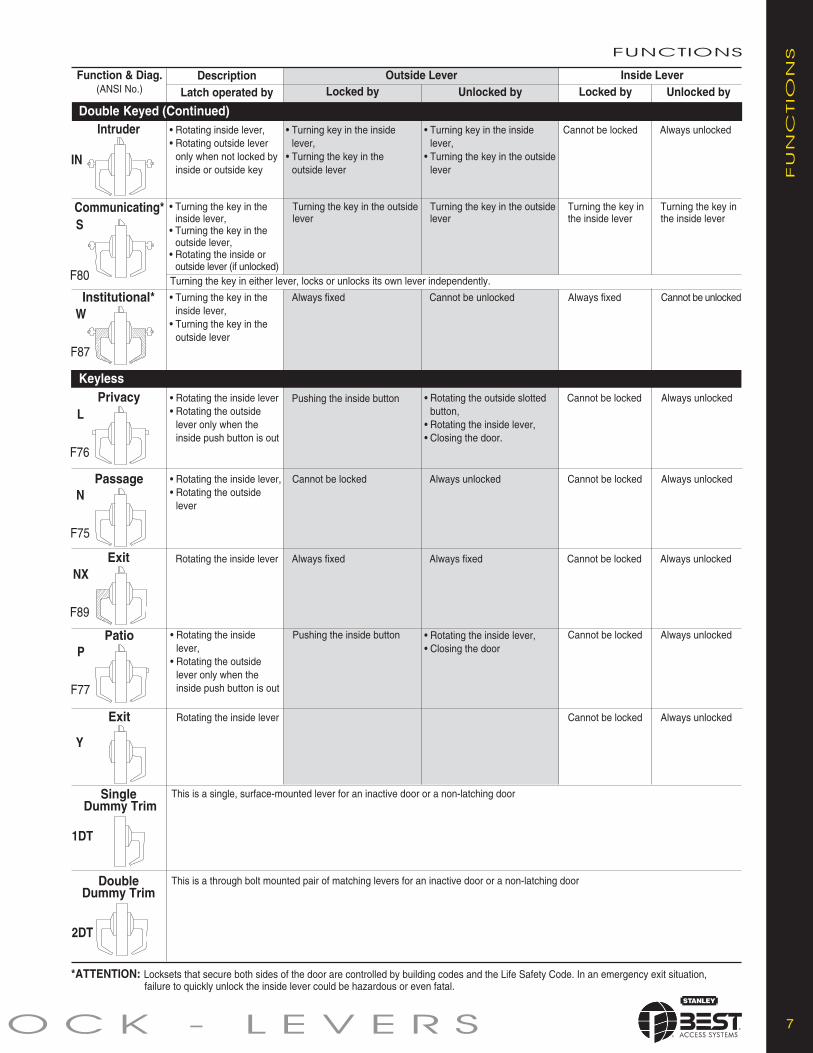
DescriptionFunction & Diag.(ANSI No.) Locked by Unlocked by Locked by Unlocked by
Inside LeverOutside LeverLatch operated by
Single Keyed
IndicatorIncluded
No Indicator
O C K - L E V E R S 7
*ATTENTION: Locksets that secure both sides of the door are controlled by building codes and the Life Safety Code. In an emergency exit situation,failure to quickly unlock the inside lever could be hazardous or even fatal.
SingleDummy Trim
2DT
DescriptionFunction & Diag.(ANSI No.) Locked by Unlocked by Locked by Unlocked by
Inside LeverOutside LeverLatch operated by
Communicating*S
F80
Institutional*W
F87
L
F76
N
F75
ExitNX
F89
PatioP
F77
Exit
Y
DoubleDummy Trim
1DT
• Turning the key in theinside lever,
• Turning the key in theoutside lever,
• Rotating the inside oroutside lever (if unlocked)
Turning the key in either lever, locks or unlocks its own lever independently.
• Turning the key in theinside lever,
• Turning the key in theoutside lever
• Rotating the inside lever• Rotating the outside
lever only when theinside push button is out
• Rotating the inside lever,• Rotating the outside
lever
Rotating the inside lever
• Rotating the insidelever,
• Rotating the outsidelever only when theinside push button is out
Rotating the inside lever
This is a single, surface-mounted lever for an inactive door or a non-latching door
This is a through bolt mounted pair of matching levers for an inactive door or a non-latching door
Turning the key in the outsidelever
Always fixed
Pushing the inside button
Cannot be locked
Turning the key in the outsidelever
Cannot be unlocked
Always fixed
• Rotating the outside slottedbutton,
• Rotating the inside lever,• Closing the door.
Always unlocked
Always fixed
Pushing the inside button
Cannot be locked
Turning the key inthe inside lever
Turning the key inthe inside lever
Always fixed Cannot be unlocked
Cannot be locked Always unlocked
Always unlocked
Cannot be locked Always unlocked
• Rotating the inside lever,• Closing the door
Cannot be locked Always unlocked
Cannot be locked Always unlocked
FU
NC
TIO
NSFUNCTIONS
IN
• Rotating inside lever,• Rotating outside lever
only when not locked byinside or outside key
Intruder • Turning key in the insidelever,
• Turning the key in theoutside lever
• Turning key in the insidelever,
• Turning the key in the outsidelever
Cannot be locked Always unlocked
Double Keyed (Continued)
Privacy
Passage
Keyless
H E AV Y D U T Y L
Always fixed
8
FU
NC
TIO
NS
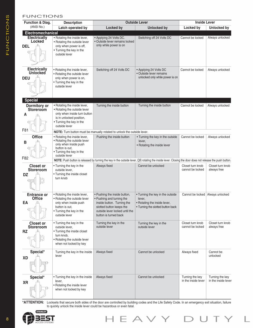
ElectricallyLocked
DEL
*ATTENTION: Locksets that secure both sides of the door are controlled by building codes and the Life Safety Code. In an emergency exit situation, failureto quickly unlock the inside lever could be hazardous or even fatal.
DescriptionFunction & Diag.(ANSI No.) Locked by Unlocked by Locked by Unlocked by
Inside LeverOutside LeverLatch operated by
Electromechanical
Special
Special*
DEU
XR
ElectricallyUnlocked
• Rotating the inside lever,• Rotating the outside lever
only when power is off,• Turning the key in the
outside lever
• Applying 24 Volts DC.• Outside lever remains locked
only while power is on
Switching off 24 Volts DC Cannot be locked Always unlocked
• Rotating the inside lever,• Rotating the outside lever
only when power is on,• Turning the key in the
outside lever
Switching off 24 Volts DC • Applying 24 Volts DC• Outside lever remains
unlocked only while power is on
Cannot be locked Always unlocked
Cannot be locked Always unlocked
A
F81
Dormitory orStoreroom
• Rotating the inside lever,• Rotating the outside lever
only when inside turn buttonis in unlocked position,
• Turning the key in theoutside lever
Turning the inside button Turning the inside button
NOTE: Turn button must be manually rotated to unlock the outside lever.
OfficeB
F82
• Rotating the inside lever,• Rotating the outside lever
only when inside pushbutton is out,
• Turning the key in theoutside lever
Pushing the inside button • Turning the key in the outsidelever,
• Rotating the inside lever
Cannot be locked Always unlocked
NOTE: Push button is released by turning the key in the outside lever, OR rotating the inside lever. Closing the door does not release the push button.
DZ
Closet orStoreroom
• Turning the key in theoutside lever,
• Turning the inside closetturn knob
Always fixed Cannot be unlocked Closet turn knobcannot be locked
Closet turn knobalways free
EA
Entrance orOffice
• Rotating the inside lever,• Rotating the outside lever
only when inside pushbutton is out,
• Turning the key in theoutside lever
• Pushing the inside button,• Pushing and turning the
inside button. Turning theslotted button keeps theoutside lever locked until thebutton is turned back
• Turning the key in the outsidelever,
• Rotating the inside lever,• Turning the slotted button back
Cannot be locked Always unlocked
Closet turn knobcannot be locked
Closet turn knobalways free
RZ
Closet orStoreroom
• Turning the key in theoutside lever,
• Turning the inside closetturn knob,
• Rotating the outside leverwhen not locked by key
Turning the key in theoutside lever
Turning the key in theoutside lever
XD
Special*
Turning the key in the insidelever
Cannot be unlocked Always fixed Cannot beunlocked
• Turning the key in the insidelever,
• Rotating the inside leverwhen not locked by key
Always fixed Cannot be unlocked Turning the keyin the inside lever
Turning the keyin the inside lever
FUNCTIONS
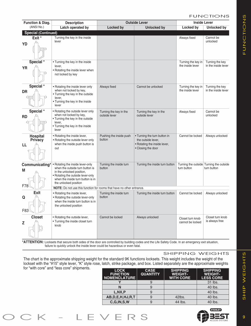
Y 9 31 lbs.N 9 40 lbs.
L,NX,P 9 40 lbs.AB,D,E,H,HJ,R,T 9 42lbs. 40 lbs.C,G,IN,S,W 9 44 lbs. 40 lbs.
9O C K - L E V E R S
FU
NC
TIO
NS
*ATTENTION: Locksets that secure both sides of the door are controlled by building codes and the Life Safety Code. In an emergency exit situation,failure to quickly unlock the inside lever could be hazardous or even fatal.
FUNCTIONS
Closet • Rotating the outside lever,• Turning the inside closet turn
knobZ
DescriptionFunction & Diag.(ANSI No.) Locked by Unlocked by Locked by Unlocked by
Inside LeverOutside LeverLatch operated by
Special (Continued)Exit *
YD
Turning the key in the insidelever
Cannot beunlocked
Always fixed
Cannot beunlocked
Always fixed
YRSpecial * • Turning the key in the inside
lever,• Rotating the inside lever when
not locked by key
Turning the key inthe inside lever
Turning the keyin the inside lever
Turning the key inthe inside lever
Turning the keyin the inside lever
Cannot be unlockedAlways fixedSpecial *DR
• Rotating the inside lever onlywhen not locked by key,
• Turning the key in the outsidelever,
• Turning the key in the insidelever
HospitalPrivacy
Special *RD
• Rotating the outside lever onlywhen not locked by key,
• Turning the key in the outsidelever,
• Turning the key in the insidelever
Turning the key in theoutside lever
Turning the key in theoutside lever
LL
• Rotating the inside lever,• Rotating the outside lever only
when the inside push button isout
Pushing the inside pushbutton
• Turning the turn button inthe outside lever,
• Rotating the inside lever,• Closing the door
Cannot be locked Always unlocked
Communicating* • Rotating the inside lever-onlywhen the outside turn button isin the unlocked position,
• Rotating the outside lever-onlywhen the inside turn button is inthe unlocked position
Turning the inside turnbutton
Turning the inside turnbutton
Turning the outsideturn button
Turning the outsideturn button
NOTE: Do not use this function for rooms that have no other entrance.
Exit • Rotating the inside lever,• Rotating the outside lever-only
when the inside turn button is inthe unlocked position
Turning the inside turn button
Cannot be locked Always unlockedTurning the inside turn button
Cannot be locked Always unlocked Closet turn knobcannot be locked
Closet turn knobis always free
M
F78
Q
F83
The chart is the approximate shipping weight for the standard 9K functions locksets. This weight includes the weight of thelockset with the “#15” style lever, “K” style rose, latch, strike package, and box. Listed separately are the approximate weightsfor “with core” and “less core” shipments.
SHIPPING WEIGHTS
SH
IPW
EIG
HTS
LOCK CASE SHIPPING SHIPPINGFUNCTION QUANTITY WEIGHT- WEIGHT-
NOMENCLATURE WITH CORE LESS CORE
10 H E AV Y D U T Y L
ACCEPTABLE MANUFACTURERS
A. Locksets and LatchsetsStanley/Best - No Substitution.
1. Locksets and latchsets: ANSI A156.2, Series 4000, Grade 1 UL listed, extra heavy-duty cylindrical type.2. Backset 2 3/4 inches (70mm)3. Interchangeable core 7-pin: [Restricted keyway] [Patented] [Standard] [ ].4. Locksets to have anti-rotational studs that are through-bolted.5. Keyed lever with no exposed keeper hole.6. Each lever to have independent spring mechanism designed to control lever only.7. Outside lever sleeve seamless, 1-piece construction, hardened steel alloy.8. Keyed Lever: Removable only after core is removed, by authorized control key, to allow access to knob keeper.9. Hub, side plate, anti-rotational studs 1-piece casting with shrouded locking lug.
B. Keys and Keying
A. Cylinders: 7-pin, interchangeable core and keyed into a [New] [Existing] factory registered Grand Masterkey Systemwith a [Standard] [Restricted] [Patented] keyway.1. Acceptable Material: Cylinders as manufactured by Best Access Systems.
B. Provide construction cores and keys during construction period. Construction control and operating keys and cores arenot part of permanent keying system or furnished on same keyway (or key section) as permanent keying system.
C. Permanent Keys and Cores: Prepare permanent cores and keys in accordance with keying schedule. [Stamp withapplicable key mark for identification.] [Do not stamp.] [ ].
D. Provide Grand Masterkeys, Masterkeys and other Security Keys.
E. Furnish keys in the following quantities:1. [4] [ ] each Grand Masterkeys.2. [4] [ ] each Masterkeys per set.3. [2] [ ] each Change keys each keyed core.4. [6] [ ] each Construction masterkeys.5. [2] [ ] each Control keys.6. Install permanent cores in locksets.
F. Return construction cores to [{Best} factory representative] [Hardware manufacurer’s representative].
MX8 – PATENTED KEYING SYSTEM
SA
MP
LE
SP
EC
IFIC
ATIO
NS
MX
8–
PA
TEN
TED
KEY
ING
SY
STEM One of the greatest threats to key control within your facility is the unauthorized duplication
of keys; one simple solution is the use of the MX8 Patented Keying System by Stanley-BestAccess Systems a patent-protected keying system.
Very seldom can a single product meet all of your exact needs, and often your level ofconvenience must be sacrificed to fit the capabilities of the product. The MX8 PatentedKeying System provides you with an significant amount of flexibility, enabling a solutionthat fits your unique balance between security and convenience.
The MX8 Patented Keying System is available in two series of keyways, the M Seriesand the X Series. Each series offers a different blend of features to help you maximizeconvenience while optimizing your security.
The MX8 Patented Keying System has the ability to provide geographic exclusivity to the customer.
M Series Keyway Features• Patented keys operate both MX8 and Standard BEST cores (backward compatibility) with existing BEST keyways (JKLM only).
Standard keys do not operate MX8 cores.• Available in large bow, long blade, and long nose key blanks to work with special applications.• Available in core designs for use in special application locks, such as high security mortise, hotel cylinders, and glass display-case locks.• Utilizes the same combinating kits and key cutting equipment as the Standard BEST keyways.• M Series keys operate MX8 cores and Standard (non-patented) BEST cores. Standard key blanks do not operate MX8 cores.
X Series Keyway Features• Distinctive key design includes thicker key blanks with larger bow for added strength and easier handling.• Keyways are unique to MX8 Patented Keying System offering even higher key duplication protection.• Requires only minor modifications to key cutting equipment to accommodate new keyways. X Series keyways utilize the standard
combinating kit, minimizing the expense of system changeover.• X Series keys only operate MX8 cores.
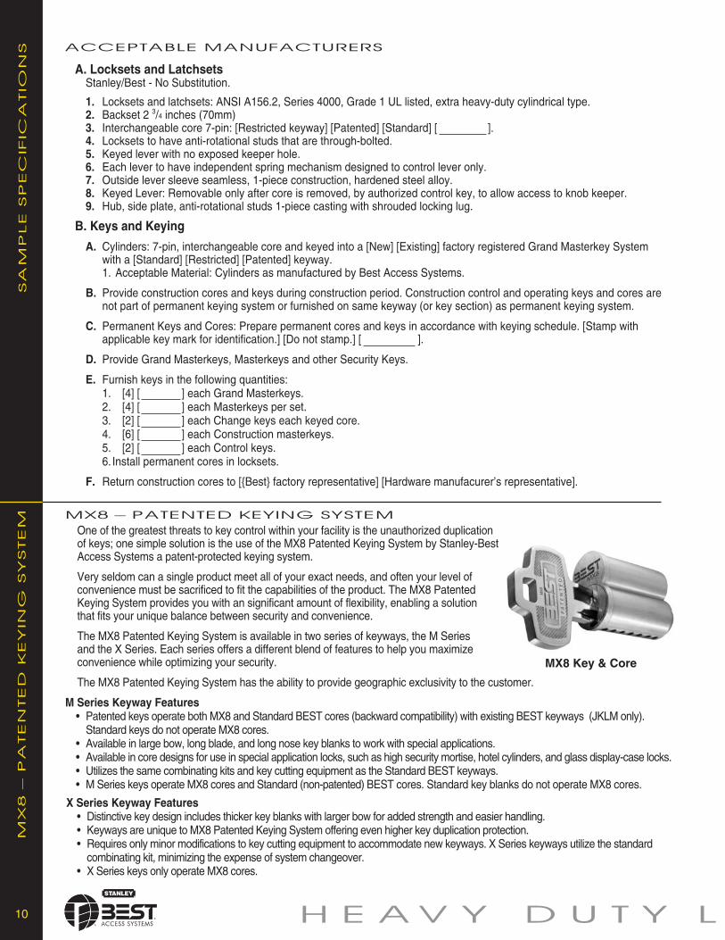
MX8 Key & Core
O C K - L E V E R S 11
STK strike (standard) S3 strike
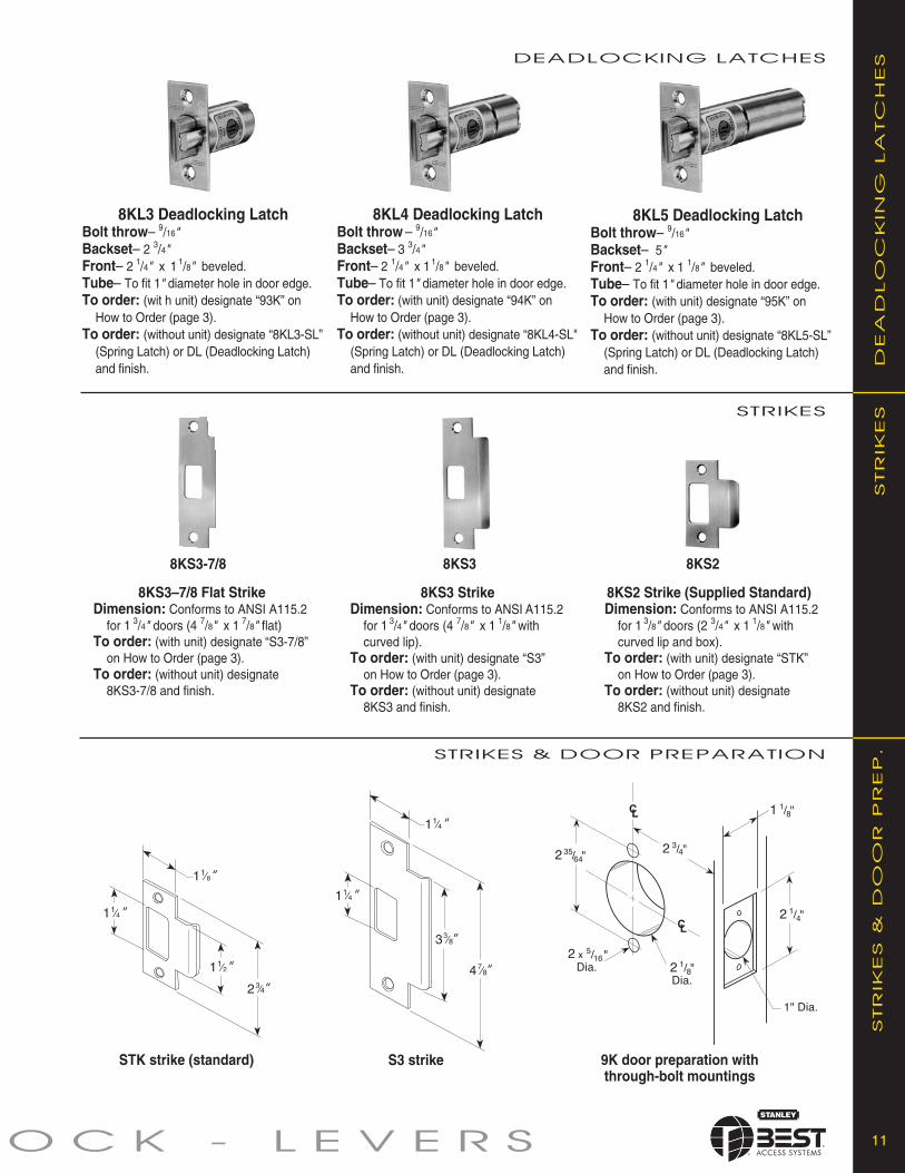
8KL5 Deadlocking LatchBolt throw– 9/16"Backset– 5"Front– 2 1/4" x 1 1/8" beveled.Tube– To fit 1" diameter hole in door edge.To order: (with unit) designate “95K” on
How to Order (page 3).To order: (without unit) designate “8KL5-SL”
(Spring Latch) or DL (Deadlocking Latch)and finish.
8KS2 Strike (Supplied Standard)Dimension: Conforms to ANSI A115.2
for 1 3/8" doors (2 3/4" x 1 1/8" withcurved lip and box).
To order: (with unit) designate “STK”on How to Order (page 3).
To order: (without unit) designate8KS2 and finish.
9K door preparation withthrough-bolt mountings
8KL4 Deadlocking LatchBolt throw– 9/16"Backset– 3 3/4"Front– 2 1/4" x 11/8" beveled.Tube– To fit 1" diameter hole in door edge.To order: (with unit) designate “94K” on
How to Order (page 3).To order: (without unit) designate “8KL4-SL"
(Spring Latch) or DL (Deadlocking Latch)and finish. D
EA
DLO
CK
ING
LA
TC
HES
8KL3 Deadlocking LatchBolt throw– 9/16"Backset– 2 3/4"Front– 2 1/4" x 1 1/8" beveled.Tube– To fit 1" diameter hole in door edge.To order: (wit h unit) designate “93K” on
How to Order (page 3).To order: (without unit) designate “8KL3-SL”
(Spring Latch) or DL (Deadlocking Latch)and finish.
8KS3 StrikeDimension: Conforms to ANSI A115.2
for 1 3/4" doors (4 7/8" x 1 1/8" withcurved lip).
To order: (with unit) designate “S3”on How to Order (page 3).
To order: (without unit) designate8KS3 and finish.
8KS28KS3
STR
IKES
DEADLOCKING LATCHES
STRIKES
STRIKES & DOOR PREPARATION
STR
IKES
&D
OO
RP
REP
.
8KS3–7/8 Flat StrikeDimension: Conforms to ANSI A115.2
for 1 3/4" doors (4 7/8" x 1 7/8" flat)To order: (with unit) designate “S3-7/8”
on How to Order (page 3).To order: (without unit) designate
8KS3-7/8 and finish.
8KS3-7/8
HEA
VY
DU
TY
CY
LIN
DR
ICA
LLO
CK
S–
LEV
ER
S
For more information on Stanley Security Solutions’ products, services, and office locations visit our web site at www.stanleysecuritysolutions.com
SSttaannlleeyy SSeeccuurriittyy SSoolluuttiioonnss,, IInncc..6161 E. 75th Street Indianapolis, Indiana 46250
www.stanleysecuritysolutions.com©2009 Stanley Security Solutions, Inc. and Stanley Logistics
Product information contained in this catalog has been com piled and presented with as much care and com plete ness as is reasonably possible. Errorsor mistakes may be present, and in many cases, reliance has been placed on information supplied by other manufacturers which may be in error orwhich may be subject to changes or mod i fi ca tions by the man u fac tur er with out no tice and without obligation. Therefore, no guar an tee can be made orshould be assumed or implied with regards to product in for ma tion con tained in this catalog.
7.5M R709FPBAS008